6.heads n valves.3
DESCRIPTION
valvesTRANSCRIPT

Cylinder Heads and ValvesCylinder Heads and Valves

Cylinder HeadsCylinder Heads PurposePurpose ConstructionConstruction
Cast IronCast IronCast AluminumCast Aluminum
Overhead valve heads incorporate:Overhead valve heads incorporate:Valves @ related componentsValves @ related componentsCoolant passagesCoolant passagesValve operation mechanism(s) Valve operation mechanism(s)

Cylinder HeadsCylinder HeadsOverhead camshaft Overhead camshaft
heads will also heads will also incorporate:incorporate:Camshaft(s)Camshaft(s)Rocker arms or Rocker arms or
followers followers


Camshaft Follower

Cylinder HeadsCylinder Heads Modern designs incorporate:Modern designs incorporate:
Squish area – the un-concaved Squish area – the un-concaved area in the combustion chamber area in the combustion chamber designed to promote turbulence.designed to promote turbulence.
Quench area – an area in the Quench area – an area in the combustion chamber designed to combustion chamber designed to cool the air/fuel mixture. cool the air/fuel mixture.

Quench AreaQuench Area

Hemispherical Cylinder Hemispherical Cylinder HeadsHeads
Hemi – a Chrysler term for a Hemi – a Chrysler term for a symmetrical cylinder design.symmetrical cylinder design.
Typically valves would be Typically valves would be positioned directly opposite in positioned directly opposite in the head with a sparkplug the head with a sparkplug positioned between them.positioned between them. Modern designs my incorporate Modern designs my incorporate
two sparkplugs. two sparkplugs. NOT exclusive to Chrysler!NOT exclusive to Chrysler!


Hemi Head

Cylinder HeadsCylinder Heads
Surface-to–volume ratioSurface-to–volume ratio – – the surface of the the surface of the combustion chamber combustion chamber divided by the volume. divided by the volume. Often near a 7.5:1 ratio.Often near a 7.5:1 ratio.If the surface area is too If the surface area is too
great fuel will condense on great fuel will condense on the surface area and not the surface area and not ignite.ignite.

Cylinder HeadsCylinder HeadsValve shroudingValve shrouding – placing – placing
the valves close to the the valves close to the walls of the combustion walls of the combustion chamber to promote chamber to promote turbulence. turbulence. This area also has a tendency This area also has a tendency
to reduce flow at high RPM. to reduce flow at high RPM.


Cylinder HeadsCylinder Heads
Cross flow head designCross flow head design – the practice of – the practice of placing the intake port placing the intake port and the exhaust port on and the exhaust port on opposite sides of the opposite sides of the cylinder head.cylinder head.


Multiple ValvesMultiple Valves Traditionally, combustion Traditionally, combustion
chambers would have one chambers would have one exhaust valve and one intake exhaust valve and one intake valve.valve.

Multiple ValvesMultiple Valves Three valve heads will have two Three valve heads will have two
intake and one exhaust valves.intake and one exhaust valves. Allows for a greater air/fuel chargeAllows for a greater air/fuel charge Lighter valves = higher RPMLighter valves = higher RPM Greater turbulence generatedGreater turbulence generated

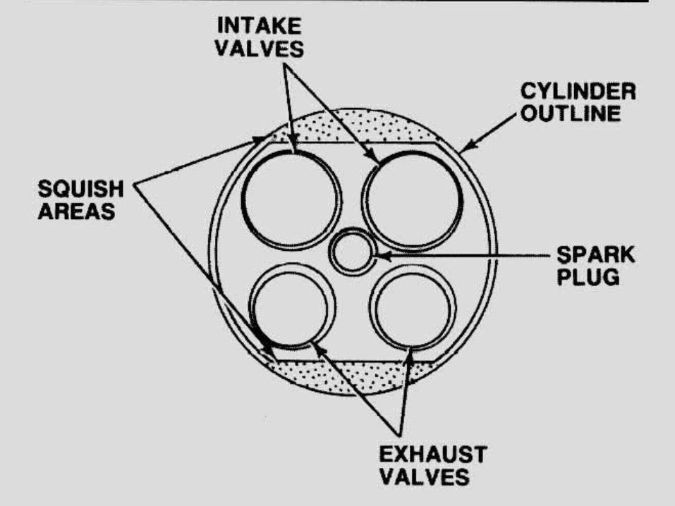
Multiple ValvesMultiple Valves Four valves per cylinder – Four valves per cylinder –
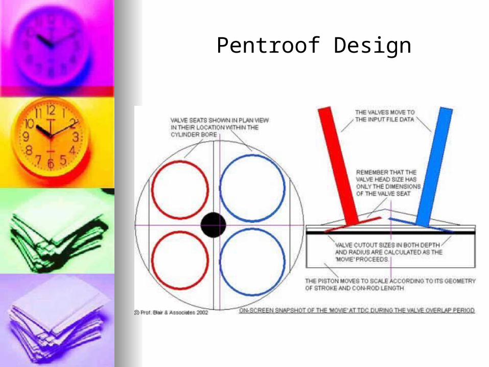
two exhaust and two intake two exhaust and two intake valves.valves.Pentroof design – each pair of Pentroof design – each pair of
valves are inlinevalves are inlineHemispherical design – each Hemispherical design – each
valve is on its own axis.valve is on its own axis. Allows for center placement of Allows for center placement of
the sparkplug.the sparkplug.
Pentroof Design

Hemispherical DesignHemispherical Design

Intake - Exhaust PortsIntake - Exhaust Ports The passageways in the The passageways in the
cylinder head that lead to/from cylinder head that lead to/from the combustion area.the combustion area.
Intake:Intake: Larger ports = more airflowLarger ports = more airflow Smaller ports = better velocity for Smaller ports = better velocity for
low RPM operationlow RPM operation Longer ports = better atomization Longer ports = better atomization
on carb and TBIon carb and TBI Shorter ports = denser A/F Shorter ports = denser A/F
charge charge
Coolant PassagesCoolant Passages Coolant travels through Coolant travels through
the cylinder head from the cylinder head from the engine block.the engine block.
Cylinder head gaskets Cylinder head gaskets may be designed to may be designed to restrict coolant flow rate.restrict coolant flow rate.Often a source for Often a source for
corrosion and leakage.corrosion and leakage.


Blown Head Gasket

Cylinder Head Removal Cylinder Head Removal All aluminum cylinder heads All aluminum cylinder heads
should be removed with a should be removed with a reverse torque procedure. reverse torque procedure.

Cylinder Head ResurfacingCylinder Head Resurfacing
Heads should be checked in Heads should be checked in five places for warpage, five places for warpage, distortion, bends or twists.distortion, bends or twists.
Check manufacturers Check manufacturers specifications, maximum specifications, maximum tolerances usually tolerances usually around .004”.around .004”.

Checking for cylinder WarpageChecking for cylinder Warpage

Valve GuidesValve Guides
The “bore” in the cylinder The “bore” in the cylinder head that supports and head that supports and controls lateral valve controls lateral valve movement.movement.Often integral on cast iron Often integral on cast iron
headsheadsAlways an insert on Always an insert on
aluminum headsaluminum heads

Valve GuidesValve Guides
Steel insert on aluminum headsSteel insert on aluminum heads
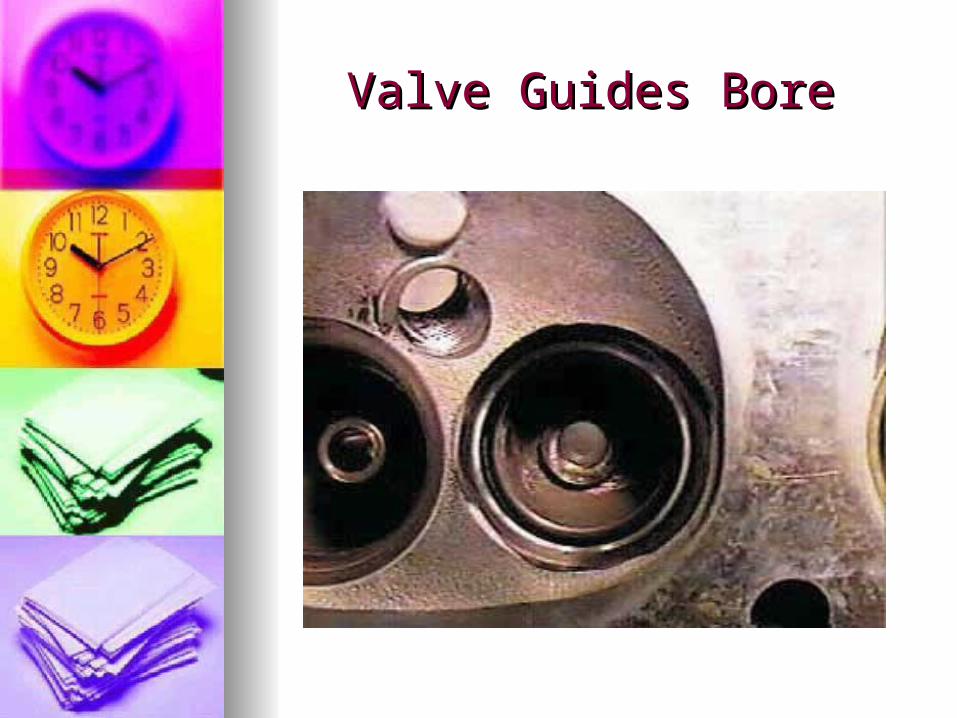
Valve Guides BoreValve Guides Bore

Valve Stem To Guide Valve Stem To Guide ClearanceClearance
Always check manufacturers Always check manufacturers specsspecs Intake valve will typically Intake valve will typically
be .001 to .003”be .001 to .003” Exhaust valve will typically Exhaust valve will typically
be .002 to .004”be .002 to .004” The exhaust valve stem The exhaust valve stem
clearance will generally be clearance will generally be greater due to the higher greater due to the higher operating temperatures.operating temperatures.

Valve Guide WearValve Guide Wear
Guides often wear “bell-Guides often wear “bell-mouthed” due to rocker mouthed” due to rocker movementmovement
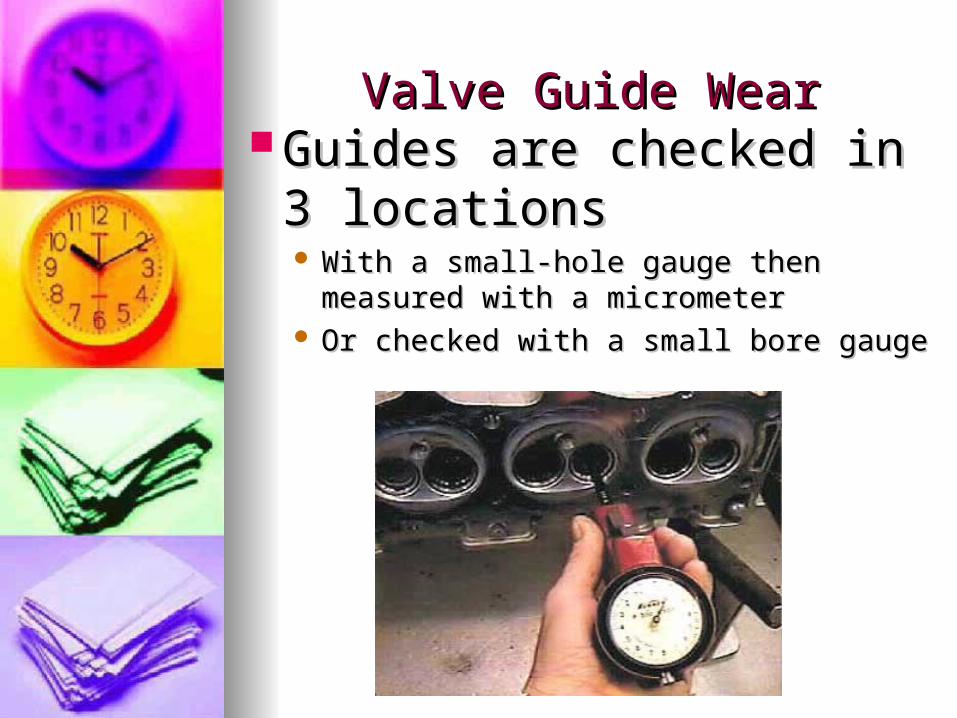
Valve Guide WearValve Guide Wear Guides are checked in 3 Guides are checked in 3
locations locations With a small-hole gauge then measured With a small-hole gauge then measured
with a micrometerwith a micrometer Or checked with a small bore gaugeOr checked with a small bore gauge

Valve Stem To Guide Clearance Valve Stem To Guide Clearance – Dial Indicator Method– Dial Indicator Method
The valve is lifted off it’s seat to it’s The valve is lifted off it’s seat to it’s maximum lift, locked into place and then maximum lift, locked into place and then checked with a dial indicator.checked with a dial indicator. This method does This method does notnot give the clearance give the clearance
directly and must be compared to specs.directly and must be compared to specs. The valve is lifted off it’s seat to it’s The valve is lifted off it’s seat to it’s
maximum lift, locked into place and then maximum lift, locked into place and then checked with a dial indicator.checked with a dial indicator. This method does This method does notnot give the clearance give the clearance
directly and must be compared to specs.directly and must be compared to specs.

Valve Stem WearValve Stem Wear Measured with a micrometer Measured with a micrometer
at three separate locations.at three separate locations.

Valve Stem To Guide Valve Stem To Guide Clearance CorrectionClearance Correction
Oversized Valve StemsOversized Valve Stems – the guide – the guide is reamed to accept a larger stem.is reamed to accept a larger stem. Must use a valve with an oversized Must use a valve with an oversized
stem.stem. Reduced flow rateReduced flow rate

Valve Stem To Guide Valve Stem To Guide Clearance CorrectionClearance Correction
Valve guide KnurlingValve guide Knurling – a tool is – a tool is driven into the guide that displaces driven into the guide that displaces metal thus reducing the inside metal thus reducing the inside diameter of the guide. (p. 340-341) diameter of the guide. (p. 340-341) The guide is then reamed to attain The guide is then reamed to attain
proper clearanceproper clearance Not recommended for clearances Not recommended for clearances
+.006+.006

Valve Stem To Guide Valve Stem To Guide Clearance CorrectionClearance Correction
Valve guide replacementValve guide replacement – – (insert) the old guide is (insert) the old guide is driven out and a driven out and a replacement guide is replacement guide is driven in. driven in.
The guide may require The guide may require reaming to achieve proper reaming to achieve proper stem to guide clearance.stem to guide clearance.

Valve Stem To Guide Valve Stem To Guide Clearance CorrectionClearance Correction
Valve Guide InsertsValve Guide Inserts – – (integral) the old guide is (integral) the old guide is drilled oversized and drilled oversized and inserts are installed.inserts are installed.Pressed fitPressed fitMay be steel or bronzeMay be steel or bronze

Valve & Valve & Seat ServiceSeat Service

Intake & Exhaust ValvesIntake & Exhaust Valves
Automotive Automotive valves are valves are of a poppet of a poppet valve valve design.design.

Valve MaterialsValve Materials Stainless steelStainless steel
May be aluminized to May be aluminized to prevent corrosionprevent corrosion
AluminumAluminumHardened valve tips and Hardened valve tips and
facesfacesStellite (nickle, chromium Stellite (nickle, chromium
and tungsten) valve tips and and tungsten) valve tips and facesfacesStellite is non-magneticStellite is non-magnetic

Valve MaterialsValve Materials Sodium-filled – a hollow stem filled Sodium-filled – a hollow stem filled
with a metallic sodium that turns to with a metallic sodium that turns to liquid when hot (heat dissipation). liquid when hot (heat dissipation).
Exhaust valves are largely comprised Exhaust valves are largely comprised of a chromium material (anti-oxidant) of a chromium material (anti-oxidant) with nickel, manganese and nitrogen with nickel, manganese and nitrogen added. added. May be heat-treatedMay be heat-treatedMay be of a two-piece designMay be of a two-piece design

Sodium Filled ValveSodium Filled Valve

Intake & Exhaust Intake & Exhaust ValvesValves
Valves are held Valves are held into place by a into place by a retainer and retainer and keeper.keeper.
Aluminum heads Aluminum heads will have a will have a separate spring separate spring seat (iron heads seat (iron heads will have integral will have integral seats) seats)

Valve SeatsValve Seats Integral seats – cast iron heads – Integral seats – cast iron heads –
induction-hardened to prevent wearinduction-hardened to prevent wear Valve seat inserts – typically aluminum Valve seat inserts – typically aluminum
heads – hardened seats are pressed into heads – hardened seats are pressed into the heads the heads

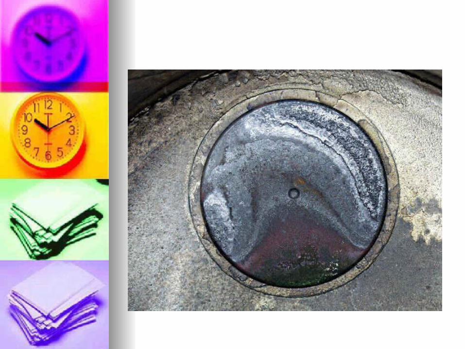
Valve InspectionValve Inspection Valve tips should not be Valve tips should not be
mushroomed mushroomed Most valve damage is due to Most valve damage is due to
excessive heat or is debris “forged”.excessive heat or is debris “forged”. Replace any valve that appears Replace any valve that appears
(355- 357)(355- 357) BurntBurnt CrackedCracked StressedStressed NeckedNecked


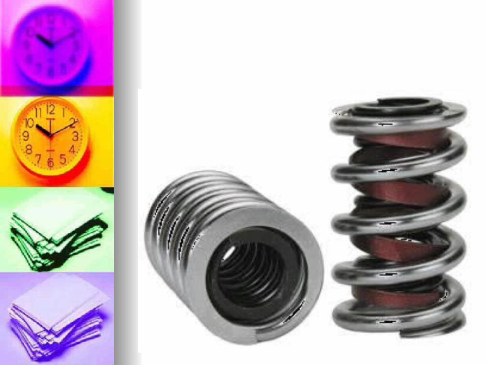
Valve SpringsValve Springs A spring “winds-up” as it is compressed – A spring “winds-up” as it is compressed –
this causes the valve to rotate.this causes the valve to rotate. May have inside dampers to control May have inside dampers to control
vibration. vibration. Springs are camshaft specific.Springs are camshaft specific.
Squareness (+ (-) .060)Squareness (+ (-) .060)Spring free height (+ (-) .060)Spring free height (+ (-) .060)Compressed force (+ (-) 10%)Compressed force (+ (-) 10%)
Valve openValve open Valve closedValve closed

Valve Spring TesterValve Spring Tester

Valve ReconditioningValve Reconditioning The stem is lightly chamfered to insure The stem is lightly chamfered to insure
proper fit in the valve grinder.proper fit in the valve grinder. The face of the valve is reground using a The face of the valve is reground using a
valve grinder. (45 or 30 degrees typical).valve grinder. (45 or 30 degrees typical). Interference angle – the practice of Interference angle – the practice of
grinding the face 1degree less than the grinding the face 1degree less than the seat angle.seat angle. The valve must retain its “margin” area.The valve must retain its “margin” area. the stem should be ground ½ the value that the stem should be ground ½ the value that
the face was ground with nonadjustable the face was ground with nonadjustable rockers. rockers.

Valve Seat ReconditioningValve Seat Reconditioning The angle of the valve The angle of the valve
seat is reconditioned.seat is reconditioned. Often 3 stage (triple-angle) Often 3 stage (triple-angle)
to promote flow and to promote flow and overhang.overhang. May be done with “seat May be done with “seat
stones”stones” May also be done with a May also be done with a
SERDI type set-up where SERDI type set-up where the 3 angles are cut with the 3 angles are cut with one cutting tip.one cutting tip.

Valve LappingValve Lapping The use of valve compound and The use of valve compound and
a suction cup stick to establish a a suction cup stick to establish a patternpattern
May be done to “freshen” the May be done to “freshen” the seat and face areasseat and face areas
Also used to check the contact Also used to check the contact pattern while cutting valve seatspattern while cutting valve seats
All compound must be removed All compound must be removed prior to serviceprior to service

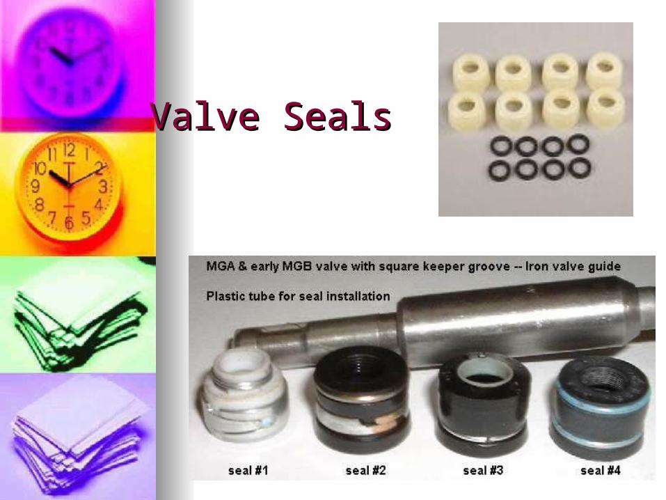
Valve SealsValve Seals Valve Seals are designed to allow Valve Seals are designed to allow
sufficient lubrication of the valve sufficient lubrication of the valve stem/guide and also control oil stem/guide and also control oil consumption.consumption.Umbrella seals – hold tightly onto the Umbrella seals – hold tightly onto the
valve stem (p.378)valve stem (p.378)Positive valve stem seals – hold Positive valve stem seals – hold
tightly onto the guidetightly onto the guideO-rings – controls oil between the O-rings – controls oil between the
spring and retainer spring and retainer
Valve SealsValve Seals

Checking Installed HeightChecking Installed Height If a valve seat and face are cut the If a valve seat and face are cut the
valve will sit lower in the head. valve will sit lower in the head. The result is that the stem will sit The result is that the stem will sit
higher on the top of the head. higher on the top of the head. This will cause the springs to have This will cause the springs to have
improper tension.improper tension. Installed height is measured and Installed height is measured and
shims are added under the spring shims are added under the spring to compensate.to compensate.
