for valtek linear control valves - flowserve · n n nonnl n y 004001 0615 2 contents. packing...
TRANSCRIPT
Experience in Motion
TECHNICAL BULLETIN
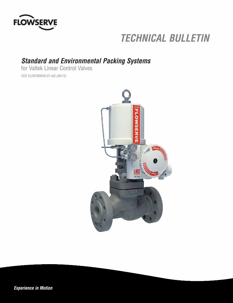
Standard and Environmental Packing Systems for Valtek Linear Control ValvesFCD VLENTB0040-01-AQ (06/15)
Standard and Environmental Packing Systems FCD VLENTB0040-01-AQ 06/15
2
ContentsPacking Selection Guidelines for Valtek Linear Control Valves 4
Introduction 4Valve Designs to Enhance Packing Performance 4Packing System Leakage Levels 4Environmental Packing Systems 5Non-Environmental 5
Environmental Packing Systems - SafeGuard 6Packing, Installation, and Maintenance 7
Environmental Packing Systems - SureGuard XT 8Packing, Installation, and Maintenance 9
Environmental Packing Systems - LATTYpack Control - EC™ 10Packing, Installation, and Maintenance 11
Environmental Packing Systems - Chesterton 5800 12Packing, Installation, and Maintenance 13
Non-Environmental Packing Systems -Standard V-Ring 14Packing, Installation, and Maintenance 15
Non-Environmental Packing Systems - Graphite Rib-Braid 16Packing, Installation, and Maintenance 17
Non-Environmental Packing Systems -Square Braided 18Packing, Installation, and Maintenance 19
3
Standard and Environmental Packing Systems FCD VLENTB0040-01-AQ 06/15
flowserve.com
FiguresFigure 1: Valtek Mark One Control Valve 4Figure 2: SafeGuard Standard and Optional Packing Configurations 6Figure 3: SafeGuard Pressure and Temperature Guidelines — Standard and Extended Bonnet 7Figure 4: SureGuard XT Standard and Optional Packing Configurations 8Figure 5: SureGuard XT Pressure and Temperature Guidelines — Standard and Extended Bonnet 9Figure 6: LATTYpack Control - EC™ Standard and Optional Packing Configurations 10Figure 7: LATTYpack Control - EC™ Pressure and Temperature Guidelines — Standard and Extended Bonnet 11Figure 8: Chesterton 5800® Standard and Optional Packing Configurations 12Figure 9: Chesterton 5800 Pressure and Temperature Guidelines — Standard and Extended Bonnet 13Figure 10: V-Ring Standard and Optional Packing Configurations 14Figure 11: V-Ring Pressure and Temperature Guidelines — Standard and Extended Bonnet 15Figure 12: Graphite Rib-Braid Standard and Optional Packing Configurations 16Figure 13: Graphite Rib-Braid Pressure and Temperature Guidelines — Standard and Extended Bonnet 17Figure 14: Square-Braided Standard and Optional Packing Configurations 18Figure 15: Square-Braided Pressure and Temperature Guidelines — Standard and Extended Bonnet 19
TablesTable 1: Environmental and Non-Environmental Packing — Selection Guidelines 5
Table 2: SafeGuard Packing Torque Values 7
Table 3: SureGuard XT Packing Torque Values 9
Table 4: LATTYpack Control - EC™ Packing Torque Values 11
Table 5: Chesterton 5800 Packing Torque Values 13
Table 6: V-Ring Packing Torque Values 15
Table 7: Graphite Rib-Braid Packing Torque Values 17
Table 8: Square-Braided Packing Torque Values 19
Standard and Environmental Packing Systems FCD VLENTB0040-01-AQ 06/15
4
Packing Selection Guidelines for Valtek® Linear Control ValvesIntroduction
This brochure provides information for selecting and specifying packing systems for linear control valve applications. Packings are classified as either environmental or non-environmental. Of these two, environmental packing systems are the more effective and reliable in linear applications where leakage levels are required to be less than 500 parts per million (ppm) or in some cases, less than 100 ppm.
Each of the packing systems shown in this brochure has various available options that can assist in meeting specific customer valve requirements. In each packing system the standard configuration is shown on the left side of each section view, while its various options are shown on the right side. In addition, pressure and temperature envelopes for standard and extended bonnets will aid in the selection of the packing configuration for a given application. Finally, installation and maintenance information will assist in achieving and sustaining the lowest leakage levels possible.
Valve Designs to Enhance Packing Performance
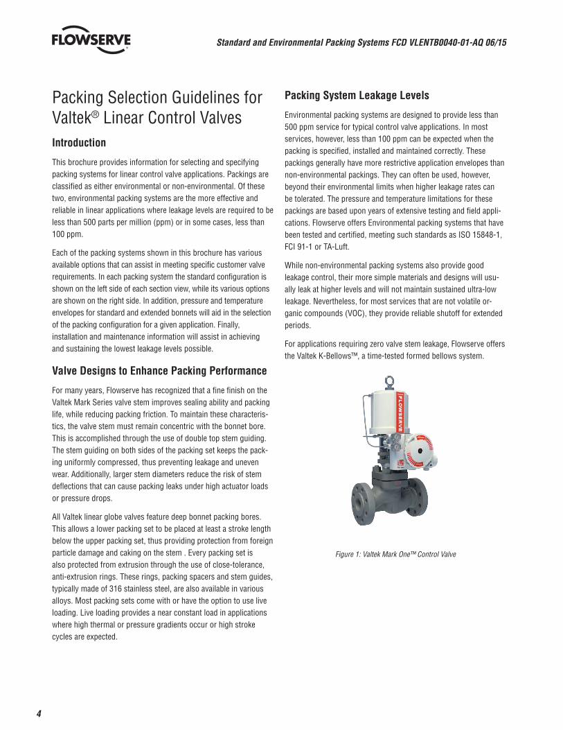
For many years, Flowserve has recognized that a fine finish on the Valtek Mark Series valve stem improves sealing ability and packing life, while reducing packing friction. To maintain these characteris-tics, the valve stem must remain concentric with the bonnet bore. This is accomplished through the use of double top stem guiding. The stem guiding on both sides of the packing set keeps the pack-ing uniformly compressed, thus preventing leakage and uneven wear. Additionally, larger stem diameters reduce the risk of stem deflections that can cause packing leaks under high actuator loads or pressure drops.
All Valtek linear globe valves feature deep bonnet packing bores. This allows a lower packing set to be placed at least a stroke length below the upper packing set, thus providing protection from foreign particle damage and caking on the stem . Every packing set is also protected from extrusion through the use of close-tolerance, anti-extrusion rings. These rings, packing spacers and stem guides, typically made of 316 stainless steel, are also available in various alloys. Most packing sets come with or have the option to use live loading. Live loading provides a near constant load in applications where high thermal or pressure gradients occur or high stroke cycles are expected.
Packing System Leakage Levels
Environmental packing systems are designed to provide less than 500 ppm service for typical control valve applications. In most services, however, less than 100 ppm can be expected when the packing is specified, installed and maintained correctly. These packings generally have more restrictive application envelopes than non-environmental packings. They can often be used, however, beyond their environmental limits when higher leakage rates can be tolerated. The pressure and temperature limitations for these packings are based upon years of extensive testing and field appli-cations. Flowserve offers Environmental packing systems that have been tested and certified, meeting such standards as ISO 15848-1, FCI 91-1 or TA-Luft.
While non-environmental packing systems also provide good leakage control, their more simple materials and designs will usu-ally leak at higher levels and will not maintain sustained ultra-low leakage. Nevertheless, for most services that are not volatile or-ganic compounds (VOC), they provide reliable shutoff for extended periods.
For applications requiring zero valve stem leakage, Flowserve offers the Valtek K-Bellows™, a time-tested formed bellows system.
Figure 1: Valtek Mark One™ Control Valve

5
Standard and Environmental Packing Systems FCD VLENTB0040-01-AQ 06/15
flowserve.com
Environmental Packing Systems
Flowserve offers the following four standard environmental packing systems for linear Valtek control valves. Other proven environmen-tal packing options may be available on request.
1. SafeGuard™
2. SureGuard XT™
3. LATTYpack Control - EC™
4. Chesterton 5800®
Each of these packing systems is capable of achieving very low leakage control for extended periods in their standard or optional configurations. Table 1 provides information to assist the user in selecting the best packing system for the application in question.
This selection can be made by considering the fluid, pressure, temperature, required options, sealing performance and stem friction. For more packing system detail, see pages 6 through 13.
Non-Environmental Packing Systems
Flowserve offers the following three non-environmental packing systems for linear Valtek control valves:
1. Standard V-ring
2. Graphite rib-braid
3. Square braid
Within the V-ring and braided packing systems, there are multiple types and choices to best suit various applications, as shown in Table 1. For more packing system detail, see pages 12 through 17.
Table 1: Environmental and Non-Environmental Packing —– Selection Guidelines
Packing System Packing Description
Maximum Pressure4
Temperature Range1
Options Availability
Test Result Availability5
Relative Sealing Perfor-mance
Relative Friction Level
Standard Bonnets
Extended Bonnets
psi bar F C F C
Envi
ronm
enta
l Pac
king
SafeGuard (Always live
loaded)
Combination of virgin and carbon-filled PTFE V-rings
3000 207-60 to 450
-51 to 232
-150 to 650
-101 to 343
Standard Twin Purge
Std. Firesafe Twin Firesafe Vacuum
T Very Good (less than 500 ppm)
Low
SureGuard XTCombination of
perfluoroelastomer and Vespel® V-rings
4000 276-20 to 550
-29 to 288
-100 to 750
-73 to 399
Standard Twin Purge Std. Firesafe Twin Firesafe Vac-uum Live Loading
CExcellent (less than 100 ppm)
Low
LATTYpack Control-EC
Combination of Latty 3265flon LM and Lattygraf
6995 NG braided rings4000 276
-50 to 500
-46 to 260
-150 to 700
-101 to 371
Standard Twin Purge Live Loading
CExcellent (less than 100 ppm)
Medium
Chesterton 5800 2
Combination of braided carbon and die-formed graphite wedge rings
2000 138-20 to 1000
-29 to 538
-100 to 1300
-73 to 704
Standard Twin Purge Live Loading
Dry 3
TVery Good (less than 500 ppm)
High
Non-
Envi
ronm
enta
l Pac
king
Standard V-Ring
Virgin PTFE V-rings 4000 276-100
to 400-73 to 204
-200 to 600
-129 to 316
Standard Twin Purge Vacuum
No Good Low
Filled PTFE V-rings 4500 310-100
to 500-73 to 260
-200 to 700
-129 to 371
Standard Twin Purge Vacuum
No Satisfactory Low
Square Braided
Square braided PTFE fibers 4500 310-100
to 500-73 to 260
-200 to 700
-129 to 371
Standard twin purge live loading
No Good Medium
Square braided carbon fibers (AFPI)
1500 103-60 to 800
-51 to 427
-160 to 1100
-29 to 593
Standard twin purge live loading
No Satisfactory Medium
Square braided graphite strands encapsulated by
wire mesh3500 238
-60 to 1200
-51 to 593
-160 to 1400
-107 to 760
Standard twin purge live loading
dryNo Good High
Graphite Rib/Braid2
Combination of braided carbon rings and die-formed
graphite square rings4000 276
-60 to 1000
-53 to 537
-160 to 1300
-107 to 704
Standard twin purge live loading
dry3
No Good High
1. Temperatures limits apply to valve body service temperature for fugitive emission performance (less than 500 ppm). Exceeding these limits may increase leakage and decrease service life.
2. The temperature of graphite packing should not exceed 427°C (800°F) in an oxidizing service such as air.
3. “Dry” graphite packing is void of binders and fillers.
4. Refer to pressure temperature graphs to see how maximum pressure may change with temperature. Consult factory for applications that exceed the pressure temperature envelopes.
5. “T” indicates Flowserve testing; “C” indicates certification by a third party test agency.
Standard and Environmental Packing Systems FCD VLENTB0040-01-AQ 06/15
6
Environmental Packing Systems —- SafeGuard
Gland Flange Bolting
Live-load Assemblywith Load Indicator
SafeGuardStandard Configuration
SafeGuardOptional Configurations
Upper Stem Guide(Alloy 6 or Bronze)
Firesafe Spacer (316 SS)
Lantern Ring (316 SS or Alloys)
Firesafe Graphite Ring(Available with standardor twin packing)
Purge Port
Twin Packing Set
Vaccum Packing (not shown)
Lower Stem Guide(Alloy 6 or Bronze)
Gland Flange
Upper Stem Guide(316 SS with
PTFE or Graphite Liner)
Anti-extrusion Ring (316 SS)
Virgin PTFE V-rings withCarbon Filled PTFE
Backup Rings
Packing Spacer(s) (316 SS)
Carbon Filled PTFE Wiper Rings
Anti Extrusion Ring (316 SS)
Lower Stem Guide(316 SS with PTFE or
Graphite Liner)
Standard Bonnet
Extended Bonnet(not shown)
Spacer (316 SS or Alloys)
(Live-loading Shown Compressed)
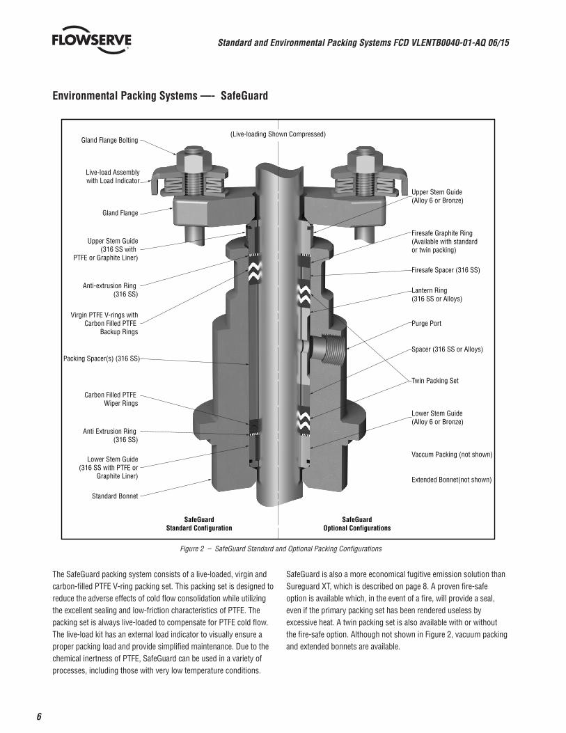
The SafeGuard packing system consists of a live-loaded, virgin and carbon-filled PTFE V-ring packing set. This packing set is designed to reduce the adverse effects of cold flow consolidation while utilizing the excellent sealing and low-friction characteristics of PTFE. The packing set is always live-loaded to compensate for PTFE cold flow. The live-load kit has an external load indicator to visually ensure a proper packing load and provide simplified maintenance. Due to the chemical inertness of PTFE, SafeGuard can be used in a variety of processes, including those with very low temperature conditions.
SafeGuard is also a more economical fugitive emission solution than Sureguard XT, which is described on page 8. A proven fire-safe option is available which, in the event of a fire, will provide a seal, even if the primary packing set has been rendered useless by excessive heat. A twin packing set is also available with or without the fire-safe option. Although not shown in Figure 2, vacuum packing and extended bonnets are available.
Figure 2 – SafeGuard Standard and Optional Packing Configurations
7
Standard and Environmental Packing Systems FCD VLENTB0040-01-AQ 06/15
flowserve.com
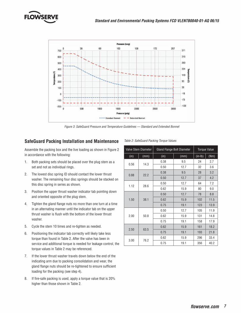
Figure 3: SafeGuard Pressure and Temperature Guidelines — Standard and Extended Bonnet
SafeGuard Packing Installation and Maintenance
Assemble the packing box and the live loading as shown in Figure 2 in accordance with the following:
1. Both packing sets should be placed over the plug stem as a set and not as individual rings.
2. The lowest disc spring ID should contact the lower thrust washer. The remaining four disc springs should be stacked on this disc spring in series as shown.
3. Position the upper thrust washer indicator tab pointing down and oriented opposite of the plug stem.
4. Tighten the gland flange nuts no more than one turn at a time in an alternating manner until the indicator tab on the upper thrust washer is flush with the bottom of the lower thrust washer.
5. Cycle the stem 10 times and re-tighten as needed.
6. Positioning the indicator tab correctly will likely take less torque than found in Table 2. After the valve has been in service and additional torque is needed for leakage control, the torque values in Table 2 may be referenced.
7. If the lower thrust washer travels down below the end of the indicating arm due to packing consolidation and wear, the gland flange nuts should be re-tightened to ensure sufficient loading for the packing (see step 4).
8. If fire-safe packing is used, apply a torque value that is 20% higher than those shown in Table 2.
Table 2: SafeGuard Packing Torque Values
Valve Stem Diameter Gland Flange Bolt Diameter Torque Value
(in) (mm) (in) (mm) (in-lb) (Nm)
0.56 14.30.38 9.5 24 2.7
0.50 12.7 32 3.6
0.88 22.20.38 9.5 28 3.2
0.50 12.7 37 4.2
1.12 28.60.50 12.7 64 7.2
0.62 15.9 80 9.0
1.50 38.1
0.50 12.7 78 8.8
0.62 15.9 102 11.5
0.75 19.1 123 13.9
2.00 50.8
0.50 12.7 105 11.9
0.62 15.9 131 14.8
0.75 19.1 158 17.9
2.50 63.50.62 15.9 161 18.2
0.75 19.1 193 21.8
3.00 76.20.62 15.9 296 33.4
0.75 19.1 356 40.2
Standard and Environmental Packing Systems FCD VLENTB0040-01-AQ 06/15
8
Environmental Packing Systems — SureGuard XT
Gland Flange Bolting
SureGuard XTStandard Configuration
SureGuard XTOptional Configurations
(Live-loading Shown Compressed)
Upper Stem Guide(Alloy 6 or Bronze)
Live-load Assemblywith Load Indicator
Lantern Ring (316 SS or Alloys)
Firesafe Spacer (316 SS)
Firesafe Graphite Ring(Available with standardor twin packing)
Purge Port
Twin Packing Set
Vaccum Packing (not shown)
Lower Stem Guide(Alloy 6 or Bronze)
Gland Flange
Upper Stem Guide(with PTFE or Graphite Liner)
Anti-extrusion Ring (316 SS)
PFE V-rings withVESPEL Backup Rings
Packing Spacer(s) (316 SS)
VESPEL Wiper Rings
Anti-extrusion Ring (316 SS)
Lower Stem Guide(316 SS with PTFE or
Graphite Liner)
Standard Bonnet
Spacer (316 SS or Alloys)
Extended Bonnet(not shown)
®
®
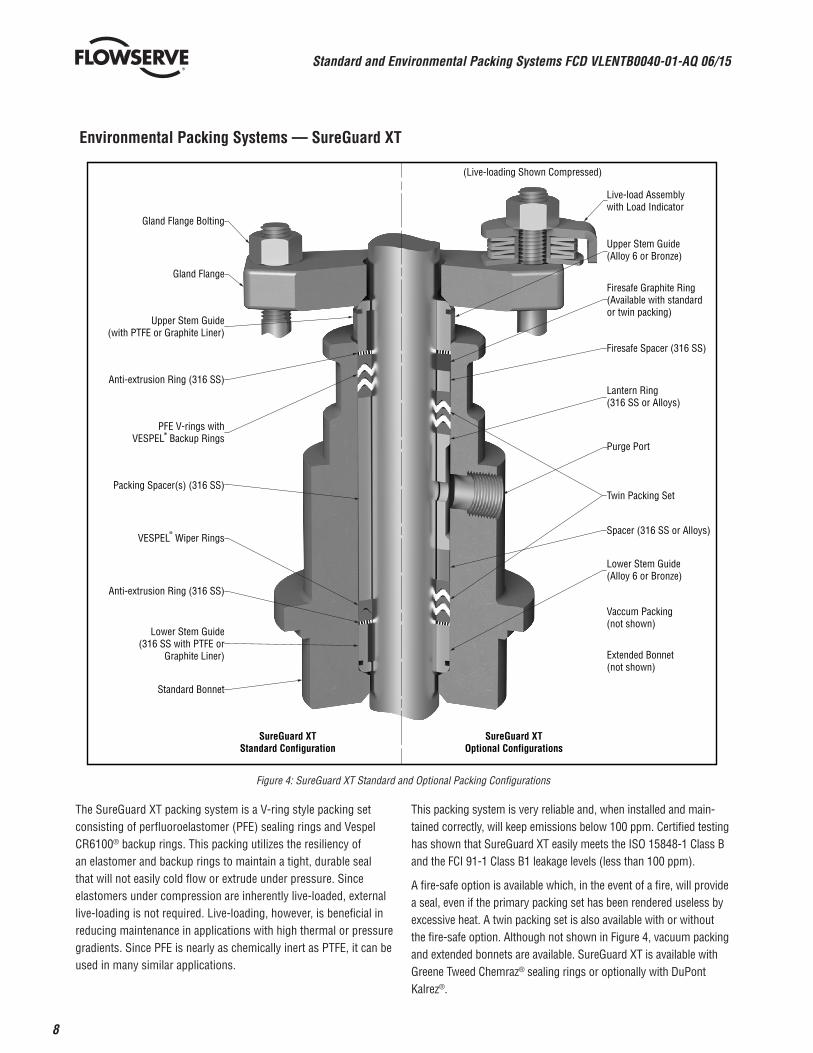
Figure 4: SureGuard XT Standard and Optional Packing Configurations
The SureGuard XT packing system is a V-ring style packing set consisting of perfluoroelastomer (PFE) sealing rings and Vespel CR6100® backup rings. This packing utilizes the resiliency of an elastomer and backup rings to maintain a tight, durable seal that will not easily cold flow or extrude under pressure. Since elastomers under compression are inherently live-loaded, external live-loading is not required. Live-loading, however, is beneficial in reducing maintenance in applications with high thermal or pressure gradients. Since PFE is nearly as chemically inert as PTFE, it can be used in many similar applications.
This packing system is very reliable and, when installed and main-tained correctly, will keep emissions below 100 ppm. Certified testing has shown that SureGuard XT easily meets the ISO 15848-1 Class B and the FCI 91-1 Class B1 leakage levels (less than 100 ppm).
A fire-safe option is available which, in the event of a fire, will provide a seal, even if the primary packing set has been rendered useless by excessive heat. A twin packing set is also available with or without the fire-safe option. Although not shown in Figure 4, vacuum packing and extended bonnets are available. SureGuard XT is available with Greene Tweed Chemraz® sealing rings or optionally with DuPont Kalrez®.
9
Standard and Environmental Packing Systems FCD VLENTB0040-01-AQ 06/15
flowserve.com
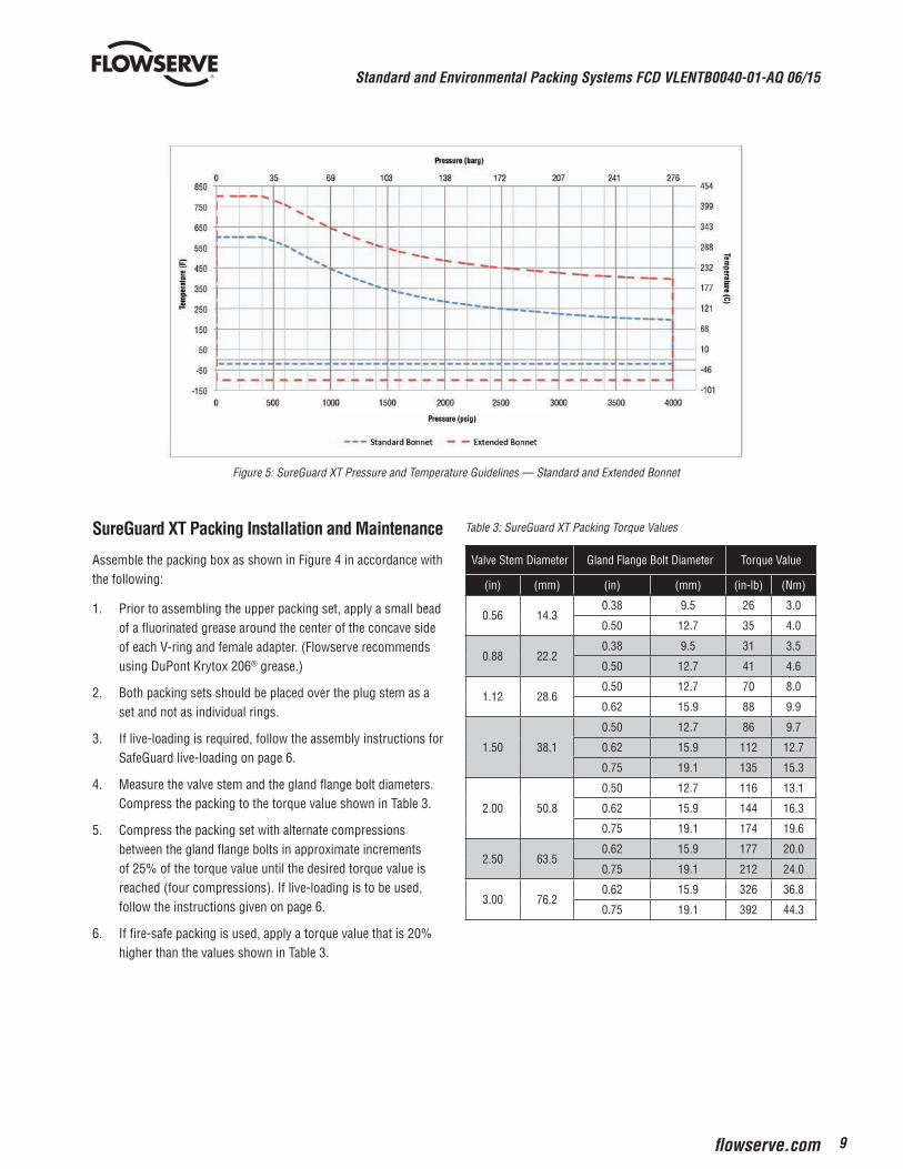
Figure 5: SureGuard XT Pressure and Temperature Guidelines — Standard and Extended Bonnet
SureGuard XT Packing Installation and Maintenance
Assemble the packing box as shown in Figure 4 in accordance with the following:
1. Prior to assembling the upper packing set, apply a small bead of a fluorinated grease around the center of the concave side of each V-ring and female adapter. (Flowserve recommends using DuPont Krytox 206® grease.)
2. Both packing sets should be placed over the plug stem as a set and not as individual rings.
3. If live-loading is required, follow the assembly instructions for SafeGuard live-loading on page 6.
4. Measure the valve stem and the gland flange bolt diameters. Compress the packing to the torque value shown in Table 3.
5. Compress the packing set with alternate compressions between the gland flange bolts in approximate increments of 25% of the torque value until the desired torque value is reached (four compressions). If live-loading is to be used, follow the instructions given on page 6.
6. If fire-safe packing is used, apply a torque value that is 20% higher than the values shown in Table 3.
Table 3: SureGuard XT Packing Torque Values
Valve Stem Diameter Gland Flange Bolt Diameter Torque Value
(in) (mm) (in) (mm) (in-lb) (Nm)
0.56 14.30.38 9.5 26 3.0
0.50 12.7 35 4.0
0.88 22.20.38 9.5 31 3.5
0.50 12.7 41 4.6
1.12 28.60.50 12.7 70 8.0
0.62 15.9 88 9.9
1.50 38.1
0.50 12.7 86 9.7
0.62 15.9 112 12.7
0.75 19.1 135 15.3
2.00 50.8
0.50 12.7 116 13.1
0.62 15.9 144 16.3
0.75 19.1 174 19.6
2.50 63.50.62 15.9 177 20.0
0.75 19.1 212 24.0
3.00 76.20.62 15.9 326 36.8
0.75 19.1 392 44.3
Standard and Environmental Packing Systems FCD VLENTB0040-01-AQ 06/15
10
Environmental Packing Systems — LATTYpack Control - EC™
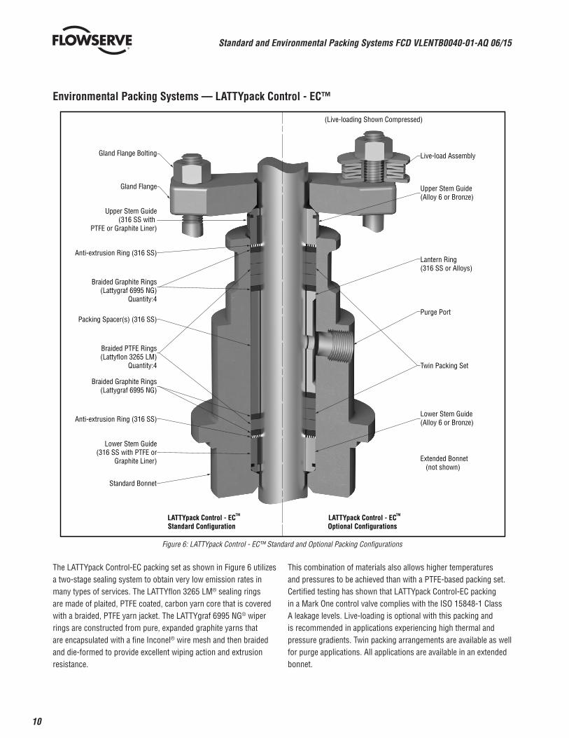
Figure 6: LATTYpack Control - EC™ Standard and Optional Packing Configurations
The LATTYpack Control-EC packing set as shown in Figure 6 utilizes a two-stage sealing system to obtain very low emission rates in many types of services. The LATTYflon 3265 LM® sealing rings are made of plaited, PTFE coated, carbon yarn core that is covered with a braided, PTFE yarn jacket. The LATTYgraf 6995 NG® wiper rings are constructed from pure, expanded graphite yarns that are encapsulated with a fine Inconel® wire mesh and then braided and die-formed to provide excellent wiping action and extrusion resistance.
This combination of materials also allows higher temperatures and pressures to be achieved than with a PTFE-based packing set. Certified testing has shown that LATTYpack Control-EC packing in a Mark One control valve complies with the ISO 15848-1 Class A leakage levels. Live-loading is optional with this packing and is recommended in applications experiencing high thermal and pressure gradients. Twin packing arrangements are available as well for purge applications. All applications are available in an extended bonnet.
Gland Flange Bolting
LATTYpack Control - ECStandard Configuration
LATTYpack Control - ECOptional Configurations
(Live-loading Shown Compressed)
Upper Stem Guide(Alloy 6 or Bronze)
Live-load Assembly
Lantern Ring (316 SS or Alloys)
Purge Port
Twin Packing Set
Lower Stem Guide(Alloy 6 or Bronze)
Extended Bonnet (not shown)
Gland Flange
Upper Stem Guide(316 SS with
PTFE or Graphite Liner)
Anti-extrusion Ring (316 SS)
Braided Graphite Rings(Lattygraf 6995 NG)
Quantity:4
Packing Spacer(s) (316 SS)
Braided PTFE Rings(Lattyflon 3265 LM)
Quantity:4
Braided Graphite Rings(Lattygraf 6995 NG)
Anti-extrusion Ring (316 SS)
Lower Stem Guide(316 SS with PTFE or
Graphite Liner)
Standard Bonnet
TM TM
11
Standard and Environmental Packing Systems FCD VLENTB0040-01-AQ 06/15
flowserve.com
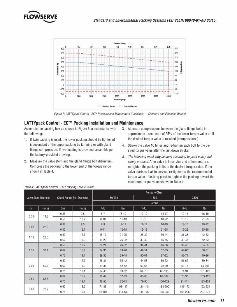
Figure 7: LATTYpack Control - EC™ Pressure and Temperature Guidelines — Standard and Extended Bonnet
Assemble the packing box as shown in Figure 6 in accordance with the following:
1. If twin packing is used, the lower packing should be tightened independent of the upper packing by tamping or with gland flange compression. If live-loading is provided, assemble per the factory-provided drawing.
2. Measure the valve stem and the gland flange bolt diameters. Compress the packing to the lower end of the torque range shown in Table 4.
3. Alternate compressions between the gland flange bolts in approximate increments of 25% of the lower torque value until the desired torque value is reached (compressions).
4. Stroke the valve 10 times and re-tighten each bolt to the de-sired torque value after the last down stroke.
5. The following must only be done according to plant policy and safety protocol. After valve is in service and at temperature, re-tighten the packing bolts to the desired torque value. If the valve starts to leak in service, re-tighten to the recommended torque value. If leaking persists, tighten the packing toward the maximum torque value shown in Table 4.
Table 4: LATTYpack Control - EC™ Packing Torque Values
Valve Stem Diameter Gland Flange Bolt Diameter
Pressure Class
150/900 1500 2500
Torque
(in) (mm) (in) (mm) ft-lb Nm ft-lb Nm ft-lb Nm
0.56 14.30.38 9.5 6-7 8-10 10-12 14-17 12-14 16-19
0.50 12.7 8-10 11-13 13-16 18-22 15-19 21-25
0.88 22.20.38 9.5 7-9 9-12 12-14 16-19 13-16 18-22
0.50 12.7 9-11 12-15 15-19 21-25 16-22 25-30
1.12 28.60.50 12.7 15-19 21-25 26-32 36-44 31-38 42-52
0.62 15.9 19-23 26-32 33-40 45-55 38-47 52-63
1.50 38.1
0.50 12.7 20-24 26-32 34-41 46-56 39-48 54-65
0.62 15.9 24-30 33-40 42-51 57-69 49-60 66-81
0.75 19.1 29-35 39-48 50-61 67-82 58-71 79-96
2.00 50.8
0.50 12.7 26-31 35-42 44-53 59-72 51-62 69-84
0.62 15.9 31-38 42-52 53-65 72-89 63-77 85-104
0.75 19.1 37-45 50-62 64-78 66-105 74-91 101-123
2.50 63.50.62 15.9 38-47 52-63 66-80 89-109 76-93 103-126
0.75 19.1 46-56 62-75 78-95 106-129 91-111 123-151
3.00 76.20.62 15.9 71-86 96-117 121-148 164-200 141-173 192-234
0.75 19.1 84-103 114-139 144-176 195-239 168-205 227-278
LATTYpack Control - EC™ Packing Installation and Maintenance
Standard and Environmental Packing Systems FCD VLENTB0040-01-AQ 06/15
12
Environmental Packing Systems — Chesterton 5800
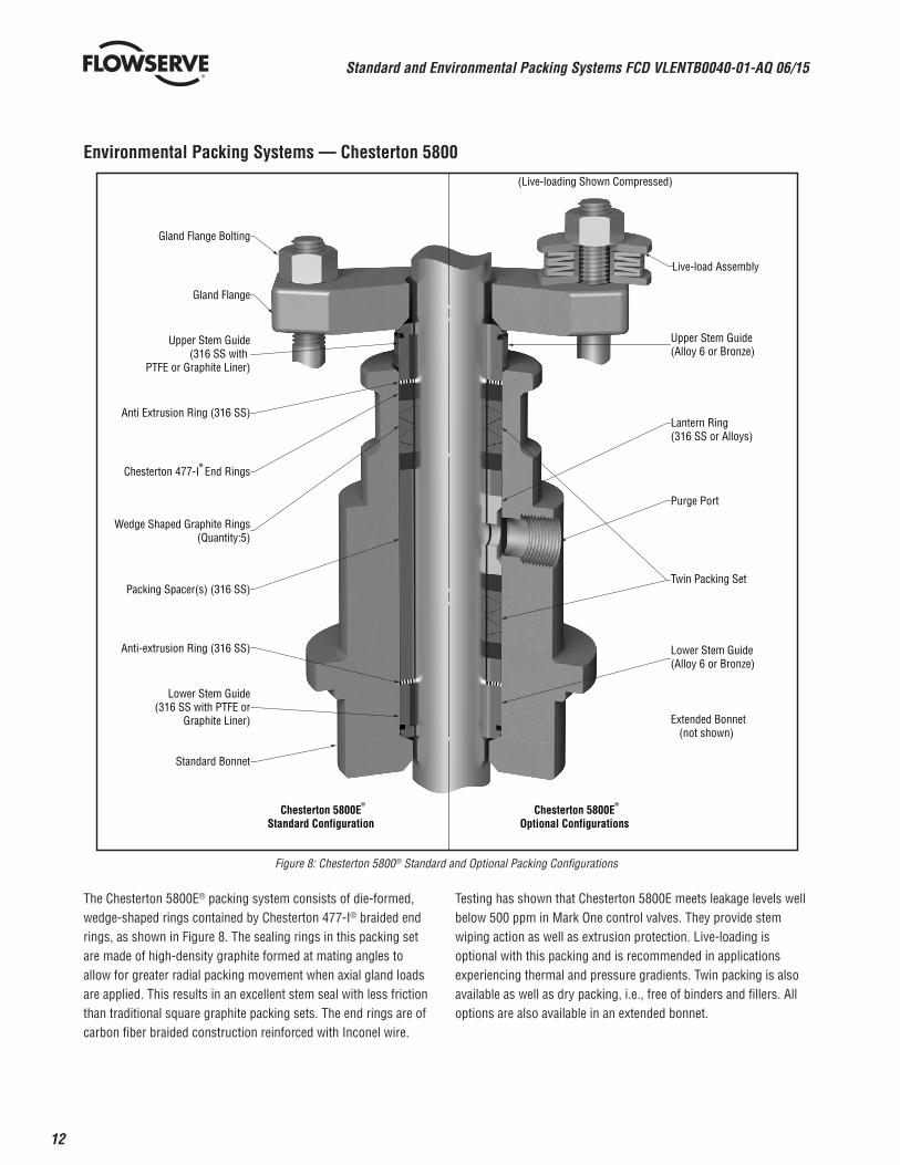
Figure 8: Chesterton 5800® Standard and Optional Packing Configurations
The Chesterton 5800E® packing system consists of die-formed, wedge-shaped rings contained by Chesterton 477-I® braided end rings, as shown in Figure 8. The sealing rings in this packing set are made of high-density graphite formed at mating angles to allow for greater radial packing movement when axial gland loads are applied. This results in an excellent stem seal with less friction than traditional square graphite packing sets. The end rings are of carbon fiber braided construction reinforced with Inconel wire.
Testing has shown that Chesterton 5800E meets leakage levels well below 500 ppm in Mark One control valves. They provide stem wiping action as well as extrusion protection. Live-loading is optional with this packing and is recommended in applications experiencing thermal and pressure gradients. Twin packing is also available as well as dry packing, i.e., free of binders and fillers. All options are also available in an extended bonnet.
Gland Flange Bolting
Chesterton 5800EStandard Configuration
Chesterton 5800EOptional Configurations
(Live-loading Shown Compressed)
Upper Stem Guide(Alloy 6 or Bronze)
Live-load Assembly
Lantern Ring (316 SS or Alloys)
Purge Port
Twin Packing Set
Lower Stem Guide(Alloy 6 or Bronze)
Extended Bonnet (not shown)
Gland Flange
Upper Stem Guide(316 SS with
PTFE or Graphite Liner)
Anti Extrusion Ring (316 SS)
Chesterton 477-I End Rings
Packing Spacer(s) (316 SS)
Wedge Shaped Graphite Rings(Quantity:5)
Anti-extrusion Ring (316 SS)
Lower Stem Guide(316 SS with PTFE or
Graphite Liner)
Standard Bonnet
®
® ®
13
Standard and Environmental Packing Systems FCD VLENTB0040-01-AQ 06/15
flowserve.com
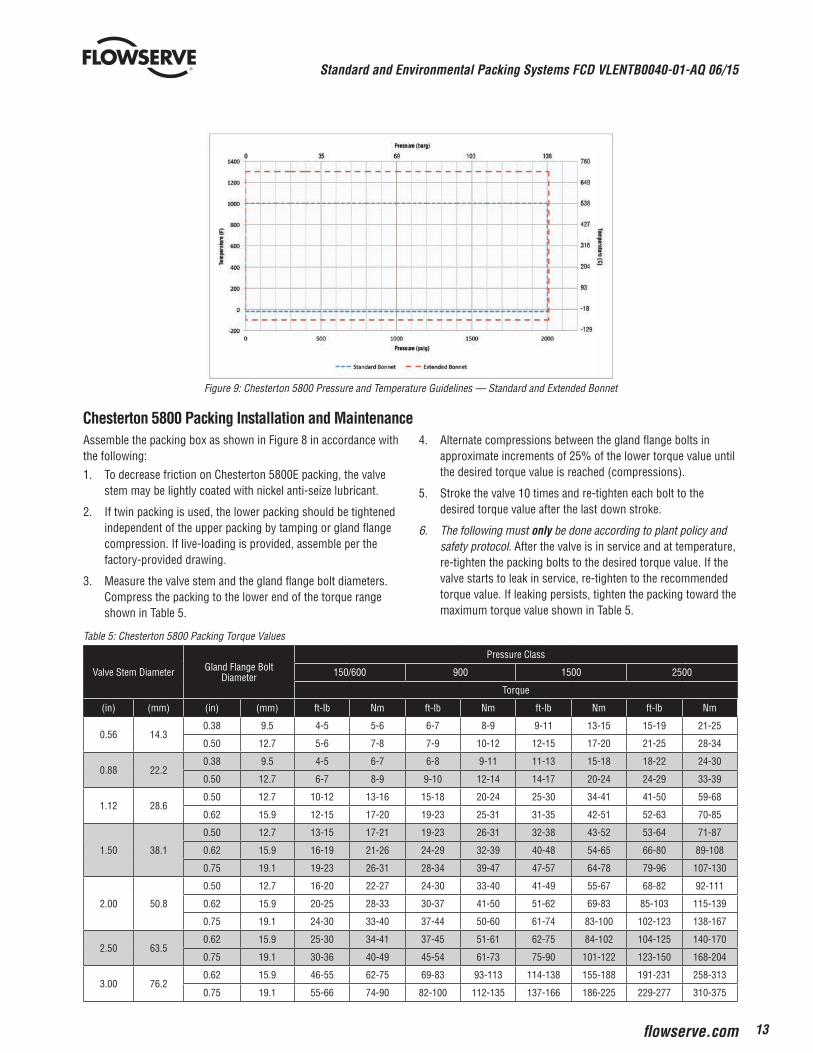
Figure 9: Chesterton 5800 Pressure and Temperature Guidelines — Standard and Extended Bonnet
Assemble the packing box as shown in Figure 8 in accordance with the following:
1. To decrease friction on Chesterton 5800E packing, the valve stem may be lightly coated with nickel anti-seize lubricant.
2. If twin packing is used, the lower packing should be tightened independent of the upper packing by tamping or gland flange compression. If live-loading is provided, assemble per the factory-provided drawing.
3. Measure the valve stem and the gland flange bolt diameters. Compress the packing to the lower end of the torque range shown in Table 5.
4. Alternate compressions between the gland flange bolts in approximate increments of 25% of the lower torque value until the desired torque value is reached (compressions).
5. Stroke the valve 10 times and re-tighten each bolt to the desired torque value after the last down stroke.
6. The following must only be done according to plant policy and safety protocol. After the valve is in service and at temperature, re-tighten the packing bolts to the desired torque value. If the valve starts to leak in service, re-tighten to the recommended torque value. If leaking persists, tighten the packing toward the maximum torque value shown in Table 5.
Table 5: Chesterton 5800 Packing Torque Values
Valve Stem Diameter Gland Flange Bolt Diameter
Pressure Class
150/600 900 1500 2500
Torque
(in) (mm) (in) (mm) ft-lb Nm ft-lb Nm ft-lb Nm ft-lb Nm
0.56 14.30.38 9.5 4-5 5-6 6-7 8-9 9-11 13-15 15-19 21-25
0.50 12.7 5-6 7-8 7-9 10-12 12-15 17-20 21-25 28-34
0.88 22.20.38 9.5 4-5 6-7 6-8 9-11 11-13 15-18 18-22 24-30
0.50 12.7 6-7 8-9 9-10 12-14 14-17 20-24 24-29 33-39
1.12 28.60.50 12.7 10-12 13-16 15-18 20-24 25-30 34-41 41-50 59-68
0.62 15.9 12-15 17-20 19-23 25-31 31-35 42-51 52-63 70-85
1.50 38.1
0.50 12.7 13-15 17-21 19-23 26-31 32-38 43-52 53-64 71-87
0.62 15.9 16-19 21-26 24-29 32-39 40-48 54-65 66-80 89-108
0.75 19.1 19-23 26-31 28-34 39-47 47-57 64-78 79-96 107-130
2.00 50.8
0.50 12.7 16-20 22-27 24-30 33-40 41-49 55-67 68-82 92-111
0.62 15.9 20-25 28-33 30-37 41-50 51-62 69-83 85-103 115-139
0.75 19.1 24-30 33-40 37-44 50-60 61-74 83-100 102-123 138-167
2.50 63.50.62 15.9 25-30 34-41 37-45 51-61 62-75 84-102 104-125 140-170
0.75 19.1 30-36 40-49 45-54 61-73 75-90 101-122 123-150 168-204
3.00 76.20.62 15.9 46-55 62-75 69-83 93-113 114-138 155-188 191-231 258-313
0.75 19.1 55-66 74-90 82-100 112-135 137-166 186-225 229-277 310-375
Chesterton 5800 Packing Installation and Maintenance
Standard and Environmental Packing Systems FCD VLENTB0040-01-AQ 06/15
14
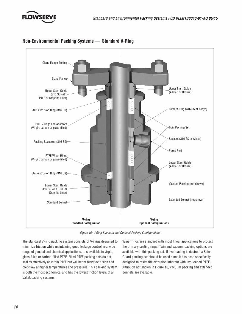
Non-Environmental Packing Systems — Standard V-Ring
Gland Flange Bolting
V-ringStandard Configuration
V-ringOptional Configurations
Upper Stem Guide(Alloy 6 or Bronze)
Lantern Ring (316 SS or Alloys)
Purge Port
Twin Packing Set
Vaccum Packing (not shown)
Lower Stem Guide(Alloy 6 or Bronze)
Gland Flange
Upper Stem Guide(316 SS with
PTFE or Graphite Liner)
Anti-extrusion Ring (316 SS)
PTFE V-rings and Adaptors(Virgin, carbon or glass-filled)
Packing Spacer(s) (316 SS)
PTFE Wiper Rings(Virgin, carbon or glass-filled)
Anti-extrusion Ring (316 SS)
Lower Stem Guide(316 SS with PTFE or
Graphite Liner)
Standard BonnetExtended Bonnet (not shown)
Spacers (316 SS or Alloys)
Figure 10: V-Ring Standard and Optional Packing Configurations
The standard V-ring packing system consists of V-rings designed to minimize friction while maintaining good leakage control in a wide range of general and chemical applications. It is available in virgin, glass-filled or carbon-filled PTFE. Filled PTFE packing sets do not seal as effectively as virgin PTFE but will better resist extrusion and cold-flow at higher temperatures and pressures. This packing system is both the most economical and has the lowest friction levels of all Valtek packing systems.
Wiper rings are standard with most linear applications to protect the primary sealing rings. Twin and vacuum packing options are available with this packing set. If live-loading is desired, a Safe-Guard packing set should be used since it has been specifically designed to resist the extrusion inherent with live-loaded PTFE. Although not shown in Figure 10, vacuum packing and extended bonnets are available.
15
Standard and Environmental Packing Systems FCD VLENTB0040-01-AQ 06/15
flowserve.com
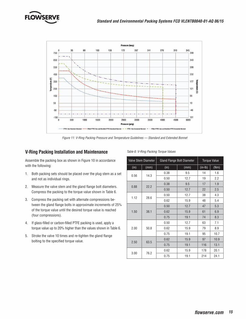
Figure 11: V-Ring Packing Pressure and Temperature Guidelines — Standard and Extended Bonnet
V-Ring Packing Installation and Maintenance
Assemble the packing box as shown in Figure 10 in accordance with the following:
1. Both packing sets should be placed over the plug stem as a set and not as individual rings.
2. Measure the valve stem and the gland flange bolt diameters. Compress the packing to the torque value shown in Table 6.
3. Compress the packing set with alternate compressions be-tween the gland flange bolts in approximate increments of 25% of the torque value until the desired torque value is reached (four compressions).
4. If glass-filled or carbon-filled PTFE packing is used, apply a torque value up to 20% higher than the values shown in Table 6.
5. Stroke the valve 10 times and re-tighten the gland flange bolting to the specified torque value.
Table 6: V-Ring Packing Torque Values
Valve Stem Diameter Gland Flange Bolt Diameter Torque Value
(in) (mm) (in) (mm) (in-lb) (Nm)
0.56 14.30.38 9.5 14 1.6
0.50 12.7 19 2.2
0.88 22.20.38 9.5 17 1.9
0.50 12.7 22 2.5
1.12 28.60.50 12.7 38 4.3
0.62 15.9 48 5.4
1.50 38.1
0.50 12.7 47 5.3
0.62 15.9 61 6.9
0.75 19.1 74 8.3
2.00 50.8
0.50 12.7 63 7.1
0.62 15.9 79 8.9
0.75 19.1 95 10.7
2.50 63.50.62 15.9 97 10.9
0.75 19.1 116 13.1
3.00 76.20.62 15.9 178 20.1
0.75 19.1 214 24.1
Standard and Environmental Packing Systems FCD VLENTB0040-01-AQ 06/15
16
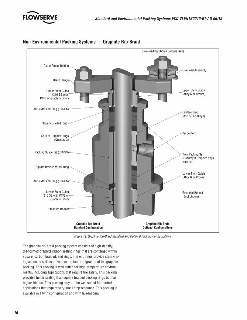
Non-Environmental Packing Systems — Graphite Rib-Braid
Figure 12: Graphite Rib-Braid Standard and Optional Packing Configurations
The graphite rib-braid packing system consists of high-density, die-formed graphite ribbon sealing rings that are contained within square, carbon braided, end rings. The end rings provide stem wip-ing action as well as prevent extrusion or migration of the graphite packing. This packing is well suited for high-temperature environ-ments, including applications that require fire safety. This packing provides better sealing than square braided packing rings but has higher friction. This packing may not be well suited for control applications that require very small step response. This packing is available in a twin configuration and with live-loading.
Gland Flange Bolting
Graphite Rib-BraidStandard Configuration
Graphite Rib-BraidOptional Configurations
(Live-loading Shown Compressed)
Upper Stem Guide(Alloy 6 or Bronze)
Live-load Assembly
Lantern Ring (316 SS or Alloys)
Purge Port
Twin Packing Set(Quantity:3 Graphite rings each set)
Lower Stem Guide(Alloy 6 or Bronze)
Extended Bonnet (not shown)
Gland Flange
Upper Stem Guide(316 SS with
PTFE or Graphite Liner)
Anti-extrusion Ring (316 SS)
Square Braided Rings
Square Graphite Rings(Quantity:3)
Packing Spacer(s) (316 SS)
Square Braided Wiper Ring
Anti-extrusion Ring (316 SS)
Lower Stem Guide(316 SS with PTFE or
Graphite Liner)
Standard Bonnet
17
Standard and Environmental Packing Systems FCD VLENTB0040-01-AQ 06/15
flowserve.com
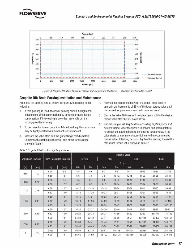
Figure 13: Graphite Rib-Braid Packing Pressure and Temperature Guidelines — Standard and Extended Bonnet
Assemble the packing box as shown in Figure 12 according to the following:
1. If twin packing is used, the lower packing should be tightened independent of the upper packing by tamping or gland flange compression. If live-loading is provided, assemble per the factory-provided drawing.
2. To decrease friction on graphite-rib braid packing, the valve stem may be lightly coated with nickel anti-seize lubricant.
3. Measure the valve stem and the gland flange bolt diameters. Compress the packing to the lower end of the torque range shown in Table 7.
4. Alternate compressions between the gland flange bolts in approximate increments of 25% of the lower torque value until the desired torque value is reached ( compressions).
5. Stroke the valve 10 times and re-tighten each bolt to the desired torque value after the last down stroke.
6. The following must only be done according to plant policy and safety protocol. After the valve is in service and at temperature, re-tighten the packing bolts to the desired torque value. If the valve starts to leak in service, re-tighten to the recommended torque value. If leaking persists, tighten the packing toward the maximum torque value shown in Table 7.
Table 7: Graphite Rib-Braid Packing Torque Values
Valve Stem Diameter Gland Flange Bolt Diameter
Pressure Class
150/600 900 1500 2500
Torque
(in) (mm) (in) (mm) ft-lb Nm ft-lb Nm ft-lb Nm ft-lb Nm
0.56 14.30.38 9.5 4-5 5-6 6-7 8-9 9-11 13-15 15-19 21-25
0.50 12.7 5-6 7-8 7-9 10-12 12-15 17-20 21-25 28-34
0.88 22.20.38 9.5 4-5 6-7 6-8 9-11 11-13 15-18 18-22 24-30
0.50 12.7 6-7 8-9 9-10 12-14 14-17 20-24 24-29 33-39
1.12 28.60.50 12.7 10-12 13-16 15-18 20-24 25-30 34-41 41-50 59-68
0.62 15.9 12-15 17-20 19-23 25-31 31-35 42-51 52-63 70-85
1.50 38.1
0.50 12.7 13-15 17-21 19-23 26-31 32-38 43-52 53-64 71-87
0.62 15.9 16-19 21-26 24-29 32-39 40-48 54-65 66-80 89-108
0.75 19.1 19-23 26-31 28-34 39-47 47-57 64-78 79-96 107-130
2.00 50.8
0.50 12.7 16-20 22-27 24-30 33-40 41-49 55-67 68-82 92-111
0.62 15.9 20-25 28-33 30-37 41-50 51-62 69-83 85-103 115-139
0.75 19.1 24-30 33-40 37-44 50-60 61-74 83-100 102-123 138-167
2.50 63.50.62 15.9 25-30 34-41 37-45 51-61 62-75 84-102 104-125 140-170
0.75 19.1 30-36 40-49 45-54 61-73 75-90 101-122 123-150 168-204
3 76.20.625 15.9 46-55 62-75 69-83 93-113 114-138 155-188 191-231 258-313
0.75 19.1 55-66 74-90 82-100 112-135 137-166 186-225 229-277 310-375
Graphite Rib-Braid Packing Installation and Maintenance
Standard and Environmental Packing Systems FCD VLENTB0040-01-AQ 06/15
18
Non-Environmental Packing Systems — Square Braided
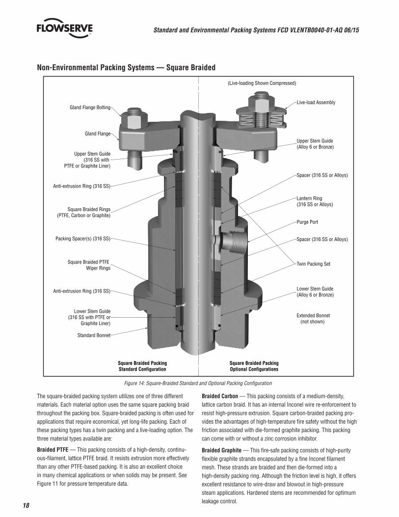
Figure 14: Square-Braided Standard and Optional Packing Configuration
The square-braided packing system utilizes one of three different materials. Each material option uses the same square packing braid throughout the packing box. Square-braided packing is often used for applications that require economical, yet long-life packing. Each of these packing types has a twin packing and a live-loading option. The three material types available are:
Braided PTFE — This packing consists of a high-density, continu-ous-filament, lattice PTFE braid. It resists extrusion more effectively than any other PTFE-based packing. It is also an excellent choice in many chemical applications or when solids may be present. See Figure 11 for pressure temperature data.
Braided Carbon — This packing consists of a medium-density, lattice carbon braid. It has an internal Inconel wire re-enforcement to resist high-pressure extrusion. Square carbon-braided packing pro-vides the advantages of high-temperature fire safety without the high friction associated with die-formed graphite packing. This packing can come with or without a zinc corrosion inhibitor.
Braided Graphite — This fire-safe packing consists of high-purity flexible graphite strands encapsulated by a fine Inconel filament mesh. These strands are braided and then die-formed into a high-density packing ring. Although the friction level is high, it offers excellent resistance to wire-draw and blowout in high-pressure steam applications. Hardened stems are recommended for optimum leakage control.
Gland Flange Bolting
Square Braided PackingStandard Configuration
Square Braided PackingOptional Configurations
(Live-loading Shown Compressed)
Upper Stem Guide(Alloy 6 or Bronze)
Lantern Ring (316 SS or Alloys)
Purge Port
Twin Packing Set
Lower Stem Guide(Alloy 6 or Bronze)
Gland Flange
Upper Stem Guide(316 SS with
PTFE or Graphite Liner)
Anti-extrusion Ring (316 SS)
Square Braided Rings(PTFE, Carbon or Graphite)
Packing Spacer(s) (316 SS)
Square Braided PTFE Wiper Rings
Anti-extrusion Ring (316 SS)
Lower Stem Guide(316 SS with PTFE or
Graphite Liner)
Standard Bonnet
Spacer (316 SS or Alloys)
Spacer (316 SS or Alloys)
Extended Bonnet (not shown)
Live-load Assembly
19
Standard and Environmental Packing Systems FCD VLENTB0040-01-AQ 06/15
flowserve.com
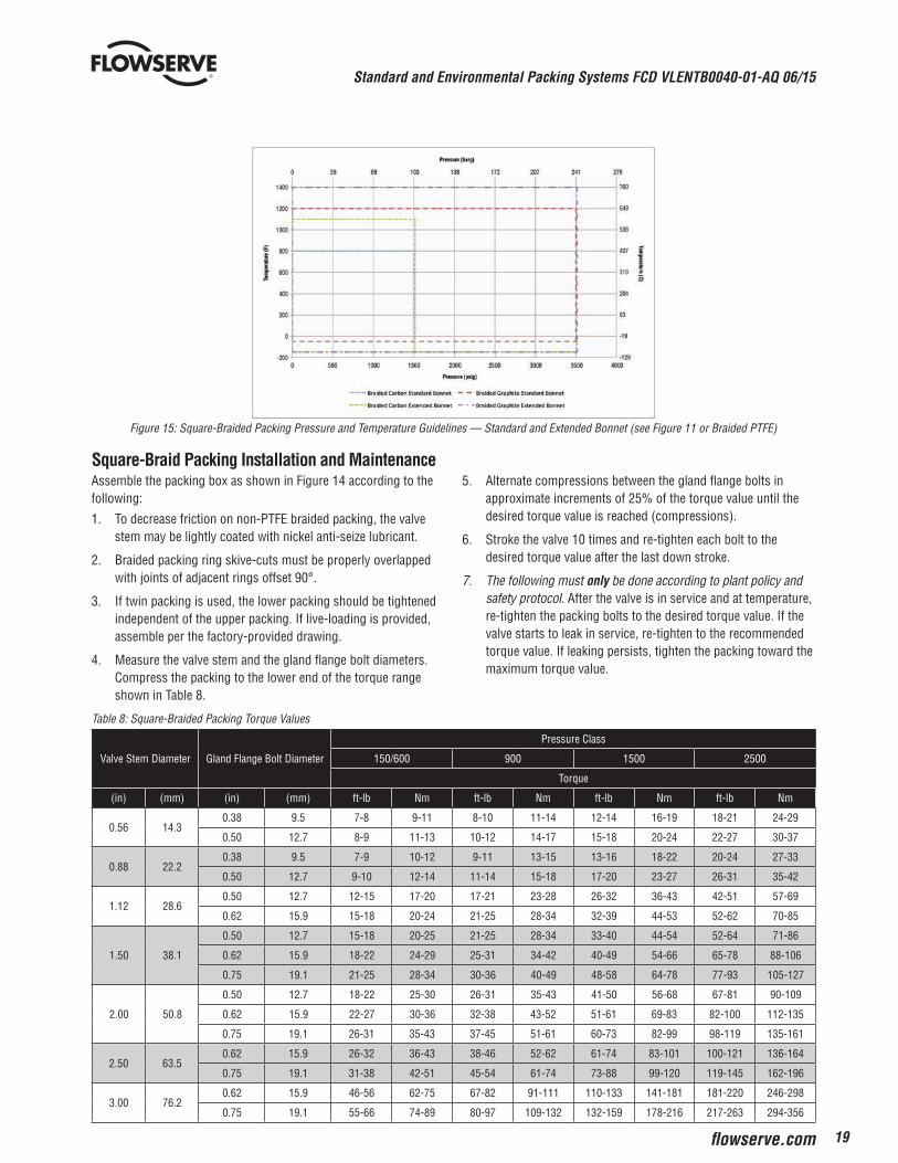
Figure 15: Square-Braided Packing Pressure and Temperature Guidelines — Standard and Extended Bonnet (see Figure 11 or Braided PTFE)
Assemble the packing box as shown in Figure 14 according to the following:
1. To decrease friction on non-PTFE braided packing, the valve stem may be lightly coated with nickel anti-seize lubricant.
2. Braided packing ring skive-cuts must be properly overlapped with joints of adjacent rings offset 90°.
3. If twin packing is used, the lower packing should be tightened independent of the upper packing. If live-loading is provided, assemble per the factory-provided drawing.
4. Measure the valve stem and the gland flange bolt diameters. Compress the packing to the lower end of the torque range shown in Table 8.
5. Alternate compressions between the gland flange bolts in approximate increments of 25% of the torque value until the desired torque value is reached (compressions).
6. Stroke the valve 10 times and re-tighten each bolt to the desired torque value after the last down stroke.
7. The following must only be done according to plant policy and safety protocol. After the valve is in service and at temperature, re-tighten the packing bolts to the desired torque value. If the valve starts to leak in service, re-tighten to the recommended torque value. If leaking persists, tighten the packing toward the maximum torque value.
Table 8: Square-Braided Packing Torque Values
Valve Stem Diameter Gland Flange Bolt Diameter
Pressure Class
150/600 900 1500 2500
Torque
(in) (mm) (in) (mm) ft-lb Nm ft-lb Nm ft-lb Nm ft-lb Nm
0.56 14.30.38 9.5 7-8 9-11 8-10 11-14 12-14 16-19 18-21 24-29
0.50 12.7 8-9 11-13 10-12 14-17 15-18 20-24 22-27 30-37
0.88 22.20.38 9.5 7-9 10-12 9-11 13-15 13-16 18-22 20-24 27-33
0.50 12.7 9-10 12-14 11-14 15-18 17-20 23-27 26-31 35-42
1.12 28.60.50 12.7 12-15 17-20 17-21 23-28 26-32 36-43 42-51 57-69
0.62 15.9 15-18 20-24 21-25 28-34 32-39 44-53 52-62 70-85
1.50 38.1
0.50 12.7 15-18 20-25 21-25 28-34 33-40 44-54 52-64 71-86
0.62 15.9 18-22 24-29 25-31 34-42 40-49 54-66 65-78 88-106
0.75 19.1 21-25 28-34 30-36 40-49 48-58 64-78 77-93 105-127
2.00 50.8
0.50 12.7 18-22 25-30 26-31 35-43 41-50 56-68 67-81 90-109
0.62 15.9 22-27 30-36 32-38 43-52 51-61 69-83 82-100 112-135
0.75 19.1 26-31 35-43 37-45 51-61 60-73 82-99 98-119 135-161
2.50 63.50.62 15.9 26-32 36-43 38-46 52-62 61-74 83-101 100-121 136-164
0.75 19.1 31-38 42-51 45-54 61-74 73-88 99-120 119-145 162-196
3.00 76.20.62 15.9 46-56 62-75 67-82 91-111 110-133 141-181 181-220 246-298
0.75 19.1 55-66 74-89 80-97 109-132 132-159 178-216 217-263 294-356
Square-Braid Packing Installation and Maintenance
To find your local Flowserve representative or for more information about Flowserve Corporation, visit www.flowserve.com or call USA 1 800 225 6989
FCD VLENTB0040-01-AQ Printed in the USA. June 2015
Flowserve Corporation has established industry leadership in the design and manufacture of its products. When properly selected, this Flowserve product is designed to perform its intended function safely during its useful life. However, the purchaser or user of Flowserve products should be aware that Flowserve products might be used in numerous applications under a wide variety of industrial service conditions. Although Flowserve can (and often does) provide general guidelines, it cannot provide specific data and warnings for all possible applications. The purchaser/user must therefore assume the ultimate responsibility for the proper sizing and selection, installation, operation, and maintenance of Flowserve products. The purchaser/user should read and understand the Installation Operation Maintenance (IOM) instructions included with the product, and train its employees and contractors in the safe use of Flowserve products in connection with the specific application.
While the information and specifications contained in this literature are believed to be accurate, they are supplied for informative purposes only and should not be considered certified or as a guarantee of satisfactory results by reliance thereon. Nothing contained herein is to be construed as a warranty or guarantee, express or implied, regarding any matter with respect to this product. Because Flowserve is continually improving and upgrading its product design, the specifications, dimensions and information contained herein are subject to change without notice. Should any question arise concerning these provisions, the purchaser/user should contact Flowserve Corporation at any one of its worldwide operations or offices.
© 2015 Flowserve Corporation, Irving, Texas, USA. Flowserve is a registered trademark of Flowserve Corporation.
USAFlowserve Flow Control Division1350 N. Mt. Springs ParkwaySpringville, UT 84663USAPhone: +1 801 489 8611Fax: +1 801 489 3719
AustriaFlowserve Control Valves GmbH Kasernengasse 69500 VillachAustriaPhone: 43 (0) 4242 41 181 0Fax: 43 (0) 4242 41181 50
FranceFlowserveFrance S.A.S.BP 60 63307 Thiers CedexFrancePhone: 33 4738 04266Fax: 33 4738 01424
IndiaFlowserve India Controls Pvt Ltd.Plot # 4, 1A, Road #8 EPIPWhitefieldBangalore, Karnataka, 560066IndiaPhone: 91 80 40146200Fax: 91 80 28410286
ChinaFlowserve Fluid Motion and Control (Suzhou) Co., Ltd. No. 35, Baiyu RoadSuzhou Industrial Park, SuzhouJiangsu Province, P.R. 215021ChinaPhone: 86 512 6288 8790Fax: 86 512 6288 8736
SingaporeFlowserve Pte. Ltd.12 Tuas Avenue 20Republic of Singapore 638824Phone: 65 6879 8900Fax: 65 6862 4940
Saudi ArabiaFlowserve Abahsain Flow Control Co., Ltd.Makkah Road, Phase 4Plot 10 & 12, 2nd Industrial CityDamman, Kingdom of Saudi ArabiaPhone: +966 3 857 3150 ext. 243Fax: +966 3 857 4243
Experience in Motion