valtek beta positioners for control valves - flowserve · valtek beta positioners general...
TRANSCRIPT

24-1Flowserve Corporation, Valtek Control Products, Tel. USA 801 489 8611Valtek No. 49035
Valtek Beta Positioners
General Information
This bulletin contains instructions for installing, cali-brating, troubleshooting, and performing maintenanceas required for the Valtek® Beta Positioner mounted oncontrol valves.
Instructions for maintaining and calibrating the NT 3000I/P module are contained in Installation, Operation,Maintenance Instructions 47, NT 3000 Series Electro-pneumatic Transducer Module. For calibration andmaintaining the remote I/P see Installation, Operation,and Maintenance Instructions 30, Electro-pneumaticTransducer.
Product users and maintenance personnel should readthoroughly and follow exactly the instructions containedin this bulletin prior to operation of the positioner. If thereis any question concerning this bulletin, call your Valtekrepresentative.
To avoid possible injury to personnel or dam-age to equipment, WARNING and CAUTIONnotes must be strictly adhered to. Modifyingthis product, substituting non-factory or infe-rior parts, or using maintenance proceduresother than outlined could drastically affect per-formance, be hazardous to personnel andequipment, and may void existing warranties.
NOTE: Numbers in parenthesis correspond to the partitem numbers in Figure 17.
Beta Positioner Overview
The Valtek Beta Positioner is available with either a pneumatic (P/P) module for air control signals or an electro-pneumatic (I/P) module for milliampere electri-cal control signals. It is double-acting, capable of sup-plying air to either side of the actuator piston while exhausting the other side to the atmosphere.
The Valtek Beta positioner can be interchanged with the 80R and XL positioners without changing the brackets or takeoff arms.
The Beta Positioner with I/P module is intrinsically safefor FM/CSA class 1, division I, groups A, B, C, and D;class II, groups E, F, and G, and CENELEC EEx ia IIc,when installed with the appropriate energy limitingsafety barriers (See Figure 1). It is also explosion prooffor FM/CSA class II, groups E, F, and G, and CENELECEEX d IIb + H2. Since the positioner is insensitive tosupply pressure changes and can handle supply pres-sures from 30 to 150 psi a supply regulator is usually notrequired; however, an air filter is highly recommended.
NOTE: The air supply should conform to ISA StandardS7.3 (a dew point at least 18°F below ambient tempera-ture, particle size below 5 microns, oil content not toexceed 1 part per million).
Positioner OperationThe Beta Positioner is a force-balanced instrument.Figure 2 shows a Beta Positioner, with either a pneu-matic or electro-pneumatic (I/P) module, installed on adouble-acting actuator for air-to-open action. Position-ing is based on a balance of two forces; one proportionalto the instrument signal and the other proportional to thestem position.
With the I/P model, the current signal is first convertedto a 3-15 psi air signal. For the pneumatic model, the3-15 psi signal is passed directly into the positioner. Thepressure signal acts upon the diaphragms in the instru-ment signal capsule creating a downward force. Themotion of the actuator stem is transmitted to the top endof the feedback spring through the follower arm andcams. As a result, tension in the feedback spring willvary as the stem position changes.
for Control Valves

24-2 Flowserve Corporation, Valtek Control Products, Tel. USA 801 489 8611
Figure 1: Intrinsically Safe Installation Schematic
Figure 2: Positioner Schematic for Air-to-Open (Retract)

24-3Flowserve Corporation, Valtek Control Products, Tel. USA 801 489 8611
A decrease in the instrument signal reverses the de-scribed actions causing a proportional downward move-ment of the actuator piston and stem.
The spool has a close tolerance to the block and a smallamount of air, 0.3 SCFM, will exhaust at the null, orequilibrium, position. This air consumption is normal.
I/P Module Operation
The I/P module receives a 30-150 psi air supply pres-sure from the Beta positioner and converts it to a 3-15 psioutput signal. This signal is proportional to a 4-20 mAinput signal or a 10-50 mA input signal depending on themodel used.
The supply pressure from the Beta Positioner is filteredas it passes through a field-replaceable, coalescing filterelement in the module. Next it passes through aninternal pressure regulator that regulates it to approxi-mately 22 psi. The air then goes through an orifice thatrestricts the flow and air consumption.
The air is further controlled to 3-15 psi using a spring-diaphragm flapper that is attracted by an electromagnetto a nozzle. A temperature compensated piezoresistivepressure sensor mounted on a circuit board senses theI/P output pressure. The pressure sensor and circuitrycreate a feedback loop, which determines how muchcurrent to send to the electromagnet for a desiredpressure output. The electromagnet in the feedbackloop varies the nozzle-flapper spacing, which regulatesthe I/P output pressure to 3-15 psi proportional to the4-20 (or 10-50 mA) input signal.
When these opposing forces balance exactly, the sys-tem will be in equilibrium and the stem will be in theposition called for by the instrument signal. If theseopposing forces are not in balance, the summing beamwill move up (or down) and, by means of the spool valve,will change the output pressures and flow rate. This willcause the piston to move until tension on the feedbackspring equalizes with the instrument signal pressure.
The detailed sequence of positioner operations are asfollows: An increase in the instrument signal forces theinstrument signal capsule and summing beam down-ward. This motion of the summing beam also pulls thepilot valve spool downward from its equilibrium position.This opens the pilot valve ports, supplying air to port 1and exhausting air from port 2. This causes the actuatorpiston to move upward.
This upward motion of the piston is transmitted back tothe positioner through the feedback linkage and camresulting in the spring being stretched proportionally tothe valve position. The piston continues to stroke up-ward until the force in the feedback spring increasessufficiently to counter the force generated by the instru-ment signal capsule. At this point, the summing beamand spool begin to return to their equilibrium position.As the valve spool ports start to close, the air flow rateto the actuator is decreased.
After the piston has reached the required position, thefeedback spring tension force will equal the force gen-erated in the instrument signal capsule. The summingbeam and instrument signal capsule will remain in theirequilibrium positions with no air flowing to the actuatoruntil a change in the instrument signal is made.
Figure 3: Positioner Mounted on Mark One with Linear Actuator
Follower Arm
Stem Clamp
Take-off Arm

24-4 Flowserve Corporation, Valtek Control Products, Tel. USA 801 489 8611
Hole A
L-R
L-D
Air-to-Open Air-to-Close (Air-to-Retract) (Air-to-Extend)
Figure 6: Return Spring / Cam Mounting(viewed from positioner’s right side)
PositionerBase
Return Spring
Hole BCam
InstallationThe installation section of this bulletin details how toinstall the positioner on linear and rotary actuators.Reversing the air action on linear and rotary actuators isalso covered along with an explanation of how to con-vert the positioner from an I/P to pneumatic or pneu-matic to I/P control signal.
Installing Positioner on Linear Actuators
Information for installing or retrofitting the Beta Posi-tioner on all sizes of linear actuators follows:
Figure 4: Beta Positioner with Pneumatic Module
Zero AdjustmentKnob
Zero AdjustmentLocking Knob
Range AdjustmentLocking Screw
Feedback Spring
PneumaticModule
Range AdjustmentGear
Range Arm
Cam
Spool Valve
Instrument SignalCapsule
NOTE: When retrofitting the Beta Positioner to anactuator equipped with a Moore or comparable posi-tioner, remove the existing positioner, bracket, stemclamp, and associated bolting. If retrofitting to an actua-tor equipped with a Valtek Beta pneumatic, system 80,or XL positioner, the same bracket, stem clamp, andbolting can be used.
1. Place the new stem clamp (if applicable) onto theactuator stem with the boss on the right side asillustrated in Figure 3.
2. Mount the positioner bracket to the yoke leg whichhas the stroke indicator plate attached to it and inthe correct position as shown in Figure 5.
Size 25, 100, 200 Size 50
Figure 5: Mounting Bracket

24-5Flowserve Corporation, Valtek Control Products, Tel. USA 801 489 8611
Figure 7: Beta Positioner with NT 3000 Transducer
3. If not welded to the stem clamp, bolt the take-off armto the stem clamp so that the arm curves upward(toward the cylinder). The holes in the follower arm(31) should line up with the slots in the take-off arm(again refer to Figure 3).
4. Referring to Figure 6, install the cam (27), cam shaft(29) and follower arm (31) for the proper air action.For air-to-open action, the cam should be installedwith the letters L-R facing toward the cam shaft andthe return spring should be fed into hole “A.” For air-to-close action, the L-D side of the cam should facetoward the cam shaft and the return spring shouldbe fed into hole “B.”
5. Feed the appropriate stroke follower arm (31) ontothe cam shaft boss (29) with the hole markingsfacing outward. Fasten securely with the lockwasher (32) and nut (33).
6. Mount positioner on the bracket. Connect thefollower arm (31) and take-off arm together withfollower pin (62). Connection must allow freemovement of follower arm.
CAUTION: Be certain to lubricate the followerpin and take-off arm where contact is made toprevent premature wear. A light industrialgrease is recommended. Failure to do so cancause premature wear, resulting in equipmentfailure and possible personal injury.
7. For air-to-open (air-to-retract) air action, tube “out-put 1” to the bottom and “output 2” to the top of thecylinder. For air-to-close (air-to-extend) action, tube“output 2” to the bottom and “output 1” to the top ofthe cylinder.
8. Attach air supply and instrument tubing, using 1/4-inch NPT tubing connections.
CAUTION: A 3-15 psi instrument signal is rec-ommended on the pneumatic module. High airpressure may damage the module; the moduleis limited to 30 psi.
Reversing Air Action on Linear ActuatorsReversing the air-action of the positioner is simple. Noadditional parts are required, although the tubing willneed to be rerouted on the linear actuator.
To reverse the air-action on all sizes of Valtek linearactuators:
1. Using Installation, Operation, Maintenance Instruc-tions 2, reverse the air-action of the actuator.
2. Disengage the return spring from the cam andremove the cam from the cam shaft.
3. Reverse the cam, return spring, and tubing for thedesired air-action by referring to steps 4-8 in the“Installing Positioner on Linear Actuators” section ofthis bulletin.
Zero Adjustment
Span Adjustment
Minimum PressureCutoff Adjustment
Current LoopTermination (+)
Current LoopTermination (-)
Terminal Block
RangeAdjustmentGear
Vent Screen
Spool Valve
Grounding Screw
Zero Adjustment Knob
Range Arm
Cam
Zero Adjustment Locking
Zero Arm
Range AdjustmentLocking Screw
Feedback Spring
Instrument SignalCapsule
Mounting Screws

24-6 Flowserve Corporation, Valtek Control Products, Tel. USA 801 489 8611
Figure 9: Installation for Cam Return Spring
Figure 8: Beta Positioner Installation on Rotary Actuator
Installing Positioner on Rotary Actuators
Proceed as follows when installing the Beta positioneron all sizes of rotary actuators if the cam and followerarm are not already installed, otherwise refer directly tostep 7.
1. Remove the feedback spring (34) and rotate thezero adjustment arm (22) out of the way. Removethe snap ring (8) from the range adjustment armpost and remove the range adjustment arm (13).
2. With the desired cam (see Table 1) and its identifi-cation letter facing towards the cam shaft, slide thecam (56) onto the end of the cam shaft having theshorter shoulder (57). (Refer to Table 1 to deter-mine desired cam characteristic). Fasten with thestar lock washer (32) and nut (33).
3. Insert the follower arm (58) into the back recess ofthe positioner with part identification number facingout. Slide the cam shaft (57) through the innerbearing and then slip the flatted hole of the followerarm (58) over the longer stepped shoulder of thecam shaft (57).
4. Place a small amount of threadlocking compound(Loctite #222 or equivalent) to the threaded portion
Screw
Return Spring
Cam
Grease Here
Cam ShaftLock Washer
Nut
Follower Pin
Actuator Lever Arm
Follower Arm
Cam
Table I: Rotary ActuatorCam Characteristic Chart
Cam FailNo. Action
B C
Valdisk and ShearStream 046467.999.000 Air-to-Open
046467.999.000 Air-to-Close C B
B C
MaxFlo
121579.999.000 Air-to-Open
160825.999.000 Air-to-Close B C
(1) Letters are the markings stamped on either side of the cam.
Equal Percent Linear
Characteristic (1)
24-7Flowserve Corporation, Valtek Control Products, Tel. USA 801 489 8611
of the cam shaft nut (59). Slide the cam shaft nut(59) through the outer bearing and screw it onto thecam shaft (57). Tighten the cam shaft togetherfirmly so that the follower arm (58) is securelyclamped. Also, make sure the cam (56) is tightlysecured to the cam shaft. Check to be sure there isno slippage. Apply a small amount of grease to thebent end of the return spring (18) and feed it throughthe hole in the cam (56). Loop the other end of thereturn spring over the screw (19) and screw it intothe positioner base.
NOTE: Screw head will not bottom out.
5. Replace the range adjustment arm (13) and its snapring (8).
6. Rotate the zero adjustment arm (22) back into placeand reinstall the feedback spring (34).
7. Insert the follower pin (62) into the hole in theactuator lever arm and drive it firmly into place witha hammer (see Figure 8).
8. Apply grease to the sliding surfaces of the followerarm (58) before mounting the positioner to thetransfer case. When mounting the positioner to thetransfer case, make sure to guide the follower arm(58) so the pin slides in the slot on the follower arm(see Figure 8). Fasten the positioner to the transfercase with the three mounting screws. Push up oncam to verify that the pin is riding in the follower armslot or remove the transfer case cover plate toinspect.
CAUTION: Failure to replace the cover-platebefore operating the actuator will cause dam-age to the shaft since the coverplate houses ashaft support bearing.
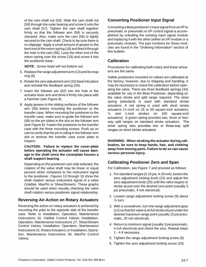
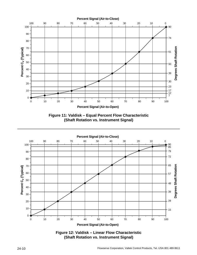
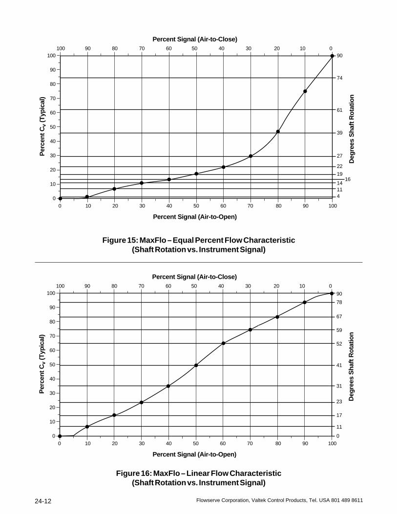
Depending on the positioner cam side selected, therotation of the valve shaft may be linear or equalpercent when compared to the instrument signalto the positioner. Figures 13 through 16 show theshaft rotation versus instrument signal of a valve(Valdisk, MaxFlo or ShearStream). These graphsshould be used when visually checking the valveshaft rotation versus positioner signal relationship.
Reversing Air-Action on Rotary ActuatorsReversing the action on rotary actuators is achieved bymounting the yoke to the opposite side of the transfercase. Refer to Installation, Operation, MaintenanceInstructions 10, Valdisk Control Valves; Installation,Operation, Maintenance Instructions 27, ShearStreamControl Valves; Installation, Operation, MaintenanceInstructions 31, Rotary Actuators; or Installation, Opera-tion, Maintenance Instructions 39, MaxFlo ControlValves.
Converting Positioner Input Signal
Converting a Beta positioner’s input signal from an I/P topneumatic or pneumatic to I/P control signal is accom-plished by unbolting the existing input signal moduleand replacing it with the other (either an I/P module or apneumatic module). The part numbers for these mod-ules are found in the “Ordering Information” section ofthis bulletin.
Calibration
Procedures for calibrating both rotary and linear actua-tors are the same.
Valtek positioners mounted on valves are calibrated at the factory; however, due to shipping and handling, it may be necessary to check the calibration before oper-ating the valve. There are three feedback springs (34) available for use in the Beta Positioner, depending on the valve stroke and split range required. The silver spring (standard) is used with standard stroke actuators. A red spring is used with short stroke actuators (1/2-inch on 25 or 50 square-inch actuators, 3/4 and 1-inch strokes on 100 square-inch actuators). A green spring provides two, three or four-way split ranges on standard stroke actuators. The silver spring also provides two or three-way split ranges on short stroke actuators
WARNING: When stroking the actuator during cali-bration, be sure to keep hands, hair, and clothingaway from moving parts. Failure to do so can causeserious personal injury.
Calibrating Positioner Zero and SpanFor Calibration, see Figure 7 and proceed as follows:
1. For standard ranges (3-15 psi, 4-20 mA), loosen thezero adjustment locking knob (23) and adjust thezero adjustment knob (20) until the valve begins tostroke at just over the desired zero point (usually 3psi pneumatic, 4 mA electrical).
2. Loosen range adjustment locking screw (9) about1/8 turn.
3. With a screwdriver, turn the range adjustment gear(12) so that the valve is at full stroke at just under thedesired maximum range point (usually 15 psi pneu-matic, 20 mA electrical).
4. Return to minimum signal (usually 3 psi pneumatic,4 mA electrical) and check the zero. Repeat steps1 - 4 if necessary.
5. Tighten the range adjustment locking screw (9).
6. Tighten the zero adjustment locking screw (23).

24-8 Flowserve Corporation, Valtek Control Products, Tel. USA 801 489 8611
Zero Adjusting Pot
Span Adjusting Pot
Minimum PressureCutoff
Grounding Screw
Circuit BoardMounting Screws
Electrical Port
Terminal Block
Adjusting Minimum Pressure Cutoff;I/P Module Pressure Regulator or ModuleOutput; Calibrating and Adjusting the NT3000 I/P
Refer to Installation, Operation, Maintenance Instruc-tions 47, NT 3000 Series Electro-pneumatic TransducerModule, for instructions on adjusting the MPC feature,adjusting the I/P module pressure regulator output,adjusting I/P module pressure modulator or calibrationof the I/P module zero and span settings.
MAINTENANCE
Beta Positioner Maintenance
General maintenance procedures for the Beta posi-tioner on both rotary and linear actuators are the same.At least once every six months, check positioner forproper operation by following the steps outlined below.
1. Maintain a clean air supply, free of dust, oil, andwater. It is recommended that an air filter be used toensure a clean air supply to positioner. Check andmaintain air filter at least every six months.
NOTE: The air supply should conform to ISAStandard S7.3 (a dew point at least 18O F belowambient temperature, particle size below 5 microns,oil content not to exceed 1 part per million).
2. Make sure all arms and levers move freely.
3. Check for and tighten any loose parts.
4. Be sure there are no leaks in the air supply.
5. Check and maintain the coalescing filter element inthe I/P module every six months.
6. Refer to the “Troubleshooting” section of this bulle-tin in case of problems.
Removal and Repair of Pilot Valve
To remove or repair the positioner pilot valve, refer toFigure 17 and proceed as follows.
1. Loosen the zero adjustment locking knob (23) andzero adjusting knob (20). Disconnect the feedbackspring (34) from the zero adjusting screw (24).Remove the feedback spring (34) from the posi-tioner assembly. Rotate the zero arm (22) out of theway before removing the snap ring (8) holding therange adjustment arm (13) to the base (7). Removethe range adjustment arm (13).
2. Remove the two screws (53) holding the pilot valveassembly (40, 52) to the base (7). Remove the pilotvalve assembly (40, 52) from the positioner, beingcareful not to damage the spool valve or summingbeam assembly (41). Slide the spool (40) from thespool valve body (52) and check it for dirt build-up
Figure 10: I/P Module Circuit Board (housing cover removed)

24-9Flowserve Corporation, Valtek Control Products, Tel. USA 801 489 8611
4. Reattach the feedback screw to the new instrumentdiaphragm assembly (49) by applying a smallamount of threadlocking compound (Loctite #222 orequivalent) to the threads. Twist the feedback screwinto the instrument diaphragm assembly (49) until itis approximately flush with the bottom of the dia-phragm assembly (49). However, make sure itdoesn’t protrude through.
5. Carefully fold up the corners of the smaller dia-phragm on the diaphragm assembly (49) and care-fully work it through the hole in the instrumentcapsule base (43). Rotate the diaphragm assemblyso the small tapped hole in the diaphragm assembly(49) hub is oriented downward closest to the mount-ing base. Install the lower diaphragm retaining plate(50) and the upper diaphragm retaining plate (42)over the diaphragm assembly (49) making sure thatall the diaphragm corners are lying flat. Install andsecurely tighten the four screws (39). Apply a smallamount of Loctite #222 to the shorter threadedportion of the spring and stud assembly (45, 46, 47)and screw it into the diaphragm center hub until thespring coil (46) bottoms out against the center hub.Thread nut (38) onto the longer portion of the studassembly until it bottoms out against the top of thecoil spring (46).
6. Reinstall the summing beam assembly (41) withfour screws (36) with a small amount of Loctite #222or equivalent applied to each screw. Be careful notto bend the thin flexures on the summing beam.With the bottom nut (38) threaded down against thetop of the spring coil (46), install the top nut (38) andtighten it firmly, attaching the summing beam as-sembly (41) to the diaphragm assembly. Install anew O-ring (48) in the instrument capsule base.Install the two mounting screws (35) and fasten theassembly securely to positioner base (7).
7. To reinstall the pilot valve assembly (40, 52), re-place the three pilot valve O-rings (54). Compressthe leaf spring on the end of the summing beamassembly (41) and carefully engage the notchedend of pilot valve assembly (40, 52) with the beamspring. Slide the pilot valve assembly (40, 52) care-fully until it is aligned with its mounting holes andfasten securely with two screws (53).
8. Return range arm (13) to the base (7) and securewith snap ring (8). Reinstall the feedback spring (34)with one end engaging the feedback screw on theinstrument diaphragm assembly (49) and the otherend engaging the zero screw (24). Then calibratepositioner according to “Calibration” section of thisdocument.
or sticking. To operate properly, the spool (40)should slide freely and fall through the spool valvebody (52) by its own weight when held vertically.Clean both the pilot valve spool (40) and body (52)with a degreasing solvent. When clean, insert thespool (40) back into the body (52) and move it backand forth to ensure that it slides freely for properoperation. If the spool (40) doesn’t slide freely,reclean or replace it.
CAUTION: Do not apply oil or grease to thespool. It will adversely affect the performance ofthe positioner.
Removal and Repair of InstrumentCapsule Assembly
To remove and repair the instrument capsule assembly,refer to Figure 4 or 17, and proceed as follows.
NOTE: If the instrument capsule assembly is damaged,the entire instrument capsule assembly with the sum-ming beam is available as a spare part and can bereplaced as a unit. It can also be disassembled and onlythe soft goods replaced.
1. To replace the entire instrument capsule assembly,first remove the pilot valve assembly (40, 52) asdescribed in steps 1 and 2 in the preceding section.Then remove the two screws (35) fastening it to thebase. Make sure the new instrument capsule O-ring(48) is installed in the base of the instrument capsuleassembly. Install the two mounting screws (35) andtighten. Reinstall the pilot valve assembly (40, 52)as described in step 7.
2. If you wish to disassemble the instrument capsuleand replace diaphragms, then proceed as follows:Remove the pilot valve assembly (40, 52) asdescribed in steps 1 and 2 of the preceding section.Remove the instrument capsule assembly from thepositioner base by removing two screws (35).Remove the nut (38) from the top of the summingbeam assembly (41). Remove the four screws (36)that attach the summing beam assembly (41) to theassembly of the instrument capsule body (43), thenremove the summing beam assembly (41).
3. Remove the four screws (39) holding the upperdiaphragm retaining plate (42) to the instrumentcapsule assembly. Remove the upper diaphragmretaining plate (42) and the lower diaphragm retain-ing plate (50) from the assembly. Carefully push thediaphragm assembly (49) through the hole and outthe bottom of the instrument capsule base. Examinethe instrument diaphragm assembly (49) for wear orfailure and replace if necessary. When replacing thediaphragm assembly (49), remove and save thefeedback screw from this assembly.
24-10 Flowserve Corporation, Valtek Control Products, Tel. USA 801 489 8611
100 90 80 70 60 50 40 30 20 10 0
0 10 20 30 40 50 60 70 80 90 100
90
74
61
50
39
30
23
17127
100
90
80
70
60
50
40
30
20
10
0
Percent Signal (Air-to-Close)
Percent Signal (Air-to-Open)
Per
cent
Cv
(Typ
ical
)
Deg
rees
Sha
ft R
otat
ion
100 90 80 70 60 50 40 30 20 10 0
0 10 20 30 40 50 60 70 80 90 100
9085
79
72
65
57
48
39
28
15
100
90
80
70
60
50
40
30
20
10
0
Percent Signal (Air-to-Close)
Percent Signal (Air-to-Open)
Per
cent
Cv
(Typ
ical
)
Deg
rees
Sha
ft R
otat
ion
Figure 11: Valdisk – Equal Percent Flow Characteristic(Shaft Rotation vs. Instrument Signal)
Figure 12: Valdisk – Linear Flow Characteristic(Shaft Rotation vs. Instrument Signal)

24-11Flowserve Corporation, Valtek Control Products, Tel. USA 801 489 8611
100 90 80 70 60 50 40 30 20 10 0
0 10 20 30 40 50 60 70 80 90 100
90
74
61
50
39
3023 17 127
100
90
80
70
60
50
40
30
20
10
0
Percent Signal (Air-to-Close)
Percent Signal (Air-to-Open)
Per
cent
Cv
(Typ
ical
)
Deg
rees
Sha
ft R
otat
ion
100 90 80 70 60 50 40 30 20 10 0
0 10 20 30 40 50 60 70 80 90 100
90
85
79
72
65
57
48
39
2815
100
90
80
70
60
50
40
30
20
10
0
Percent Signal (Air-to-Close)
Percent Signal (Air-to-Open)
Per
cent
Cv
(Typ
ical
)
Deg
rees
Sha
ft R
otat
ion
Figure 13: ShearStream – Equal Percent Flow Characteristic(Shaft Rotation vs. Instrument Signal)
Figure 14: ShearStream – Linear Flow Characteristic(Shaft Rotation vs. Instrument Signal)
24-12 Flowserve Corporation, Valtek Control Products, Tel. USA 801 489 8611
100 90 80 70 60 50 40 30 20 10 0
0 10 20 30 40 50 60 70 80 90 100
90
74
61
39
27
22
19 1614114
100
90
80
70
60
50
40
30
20
10
0
Percent Signal (Air-to-Close)
Percent Signal (Air-to-Open)
Per
cent
Cv
(Typ
ical
)
Deg
rees
Sha
ft R
otat
ion
100 90 80 70 60 50 40 30 20 10 0
0 10 20 30 40 50 60 70 80 90 100
90
78
67
59
52
41
31
23
17
11
0
100
90
80
70
60
50
40
30
20
10
0
Percent Signal (Air-to-Close)
Percent Signal (Air-to-Open)
Per
cent
Cv
(Typ
ical
)
Deg
rees
Sha
ft R
otat
ion
Figure 15: MaxFlo – Equal Percent Flow Characteristic(Shaft Rotation vs. Instrument Signal)
Figure 16: MaxFlo – Linear Flow Characteristic(Shaft Rotation vs. Instrument Signal)

24-13Flowserve Corporation, Valtek Control Products, Tel. USA 801 489 8611
* All of the above parts are in stock, and can be purchased in any one of 34 spare parts kits. For selecting and ordering the appropriate kitor a new positioner, contact your Valtek representative or the factory.
Figure 17: Beta Positioner – Exploded View
61. Snap rings62. Follower pin63. Nut64. Lock washer65. Nut66. Pneumatic adapter67. Bolt, socket head69. O-ring70. I/P module assembly73. Bolt, socket head74. Snap ring75. Vent screen76. Ball77. Post78. Bushing, rotary
101. Instrument diaphragm assembly102. Zero adjusting arm assembly103. Range arm assembly129. O-ring, vented
40. Spool41. Summing beam assembly42. Upper diaphragm retaining plate43. Diaphragm base45. Stud46. Spring47. Stud48. Instrument capsule O-ring49. Instrument diaphragm assembly50. Lower diaphragm retaining plate52. Spool valve body53. Screw54. Spool valve O-rings55. Cam shaft, rotary, vented56. Cam, rotary57. Cam shaft, rotary58. Follower arm, rotary59. Cam shaft nut, rotary60. Cap, rotary
20. Zero adjustment knob21. Snap ring22. Zero arm23. Zero adjustment lock knob24. Zero adjusting screw25. Pivot26. Lock washer27. Cam, linear28. Bushing, linear29. Cam shaft, linear30. Cam shaft, linear, vented31. Follower arm32. Lock washer33. Nut34. Feedback spring35. Screw36. Screw38. Nut39. Screw
Positioner Parts List*
1. Cover2. Screw3. Gasket4. O-ring5. Pressure gauge 0-150 psi6. Pressure gauge 0-30 psi7. Base8. Snap ring9. Pivot screw
10. Pivot bushing11. Front range plate12. Range adjustment gear13. Range adjustment arm14. Rear range plate15. Bearing16. Screw17. Snap ring18. Return spring19. Screw

24-14 Flowserve Corporation, Valtek Control Products, Tel. USA 801 489 8611
Table III: Linear Actuator Follower Arms
Actuator Stroke Spud FollowerSize (inch) (inch) Arm Kit
25 1/4 2.00 055895.999.000*(3)
25 3/8 2.00 055895.999.000*(3)
25 1/2 2.00 048624.999.000
25 3/4 - 11/2 2.00 048624.999.000
50 1/4 2.00 080647.999.000(3)
50 3/4 - 11/2 2.00 048624.999.000
50 3/4 - 11/2 2.62 056098.999.000
50 3 2.62 048625.999.000
100 / 200 3/4 - 3 2.62 - 2.88 048625.999.000
100 / 200 3/4 - 4 3.38 - 4.75 048626.999.000
100 / 200 5 - 8 3.38 - 4.75 048627.999.000
* Requires the use of stem clamp number 055679.164.000(3) Use short-stroke positioners with: 25 sq. in. actuator, 1/4, 3/8 with
stroke; 50 sq. in. actuator, 1/4-inch stroke.
Ordering InformationThe following information is provided to order a new Betapositioner or to adapt an existing positioner from oneapplication to another.
Linear ActuatorsWhen ordering a positioner for a linear actuator, selecttwo part numbers; one each from Tables 2 and 3.
Table II: Positioner Model with 3-15 psior 4-20 mA span for Linear Actuators(1)
Air P/P NT 3000Action Module I/P Module
Air-to-Open(2) 130122.999.000 167981.999.000
Air-to-Close 130157.999.000 167982.999.000
Air-to-Open(2) 130158.999.000 167983.999.000
Air-to-Close 130159.999.000 171787.999.000
(1) Can be split ranged 2:1 or 3:1 without additional parts. Alsoavailable are positioner models with 6-30 psi or 10-50 mAspan and the same split ranges.
(2) The cam can be turned over in the field for opposite air action.
Stroke
Stand.
Short
Rotary ActuatorsWhen ordering a positioner for a rotary actuator, selecttwo part numbers; one from Table IV and one from TableV which includes part numbers for the follower arm.
Table IV: Positioner Model with 3-15 psior 4-20 mA span for Rotary Actuators(1)
Valve Installed P/P NT 3000Type Cam(4) Module I/P Module(5)
Valdisk or Shear Stream
B(4) 130326.999.000 167985.999.000
C(4) 130327.999.000 167986.999.000
MaxFlo
Air-to-Open B (eq. per.) 130975.999.000 167989.999.000
Air-to-Close B (eq. per.) 161127.999.000 171236.999.000
Air-to-Open C (Linear) 130978.999.000 171235.999.000
Air-to-Close C (Linear) 161154.999.000 171269.999.000
(1) Can be split ranged 2:1 or 3:1 without additional parts. Alsoavailable are positioner models with 6-30 psi or 10-50 mA spanand the same split ranges.
(4) The cam can be turned over in the field to the opposite side “B”or “C”. To select the correct positioner model choose either “B”or “C” from the “Cam Characteristic” chart in Table I.
(5) FM/CSA Explosion Proof and Intrinsically Safe rating.
Actuator Size Follower Arm(Square-inches) Part Number
25 042817.999.000 50 042816.999.000
100 / 200 041418.999.000
When installed on a rotary valve, the signal vs. CV rela-tionship can be equal percentage or linear, based on airaction as well as cam characteristics. See Table 1.
Several kits are available to convert the Beta positionercontrol signal from either pneumatic to I/P, or from I/P topneumatic.
Table VI: Conversion Kits(1)
Module Number
I/P to Pneumatic 041694.999.000
Pneumatic to I/P
(FM/CSA Exp. Proof. I.S.) 164672.999.000
(Cenelec I.S. w/M20 connection) 167926.999.000
(Cenelec I.S. w/1/2" NPT connection) 171586.999.000
(Cenelec Exp. Proof w/M20 connection) 171971.999.000
(Cenelec Exp. Proof w/1/2" NPT connection) 173444.999.000
(1) Conversion kits include I/P or pneumatic module, two screws(item 67 or 73), two O-rings (item 69), and a standard gauge(item 6). See Figure 17 for reference to item numbers.
Table V: Follower Arms - Rotary Actuators

24-15Flowserve Corporation, Valtek Control Products, Tel. USA 801 489 8611
SPARE PART KITS
BETA POSITIONER (see Figure 17)
Kit 1 - Standard Part No. 043984.999.000
Item No. Description Quantity
40, 52 Pilot valve assembly 1
53 Screw 2
54 Spool valve O-rings 3
Kit 2 - Standard w/EPDM O-rings Part No. 063528.999.000
Item No. Description Quantity
40, 52 Pilot valve assembly 1
53 Screw 2
54 Spool valve O-rings 3
Kit 3 - Standard w/Viton O-rings Part No. 033451.999.000
Item No. Description Quantity
40, 52 Pilot valve assembly 1
53 Screw 2
54 Spool valve O-rings 3
Kit 4 - Standard w/extended temperature O-rings Part No. 046710.999.000
Item No. Description Quantity
40, 52 Pilot valve assembly 1
53 Screw 2
54 Spool valve O-rings 3
Kit 5 - High flow w/Buna-N O-rings Part No. 075171.999.000
Item No. Description Quantity
40, 52 Pilot valve assembly 1
53 Screw 2
54 Spool valve O-rings 3
Kit 6 - High flow w/extended temperature O-rings Part No. 081575.999.000
Item No. Description Quantity
40, 52 Pilot valve assembly 1
53 Screw 2
54 Spool valve O-rings 3
ZERO ARM KITSKit 7 - No split range (Standard Stroke) 2, 3-way split range (Short Stroke) Part No. 125250.999.000
Item No. Description Quantity
21 Snap ring 134 Feedback spring 1
102 Zero adjustment arm assembly 1(includes item No. 20, 22, 23, 24, 25)
Kit 8 - 2, 3, 4-way split range (Standard Stroke) Part No. 130165.999.000
Item No. Description Quantity
21 Snap ring 134 Feedback spring 1
102 Zero adjustment arm assembly 1(includes item No. 20, 22, 23, 24, 25)
Kit 9 - 1/2-inch stroke No Split Range Part No. 130164.999.000
Item No. Description Quantity
21 Snap ring 134 Feedback spring 1
102 Zero adjustment arm assembly 1(includes item No. 20, 22, 23, 24, 25)

24-16 Flowserve Corporation, Valtek Control Products, Tel. USA 801 489 8611
CAM KITS (Rotary Valves)Kit 14 - Standard Part No. 048444.999.000
Item No. Description Quantity
18 Return spring 119 Screw 133 Nut 132 Lock washer 156 Cam (rotary) 157 Cam shaft (rotary) 159 Cam shaft nut (rotary) 160 Cap (rotary) 1
Kit 15 - Standard w/O-ring groove for ventedpositionerPart No. 074910.999.000
Item No. Description Quantity
18 Return spring 119 Screw 133 Nut 132 Lock washer 155 Cam shaft (rotary, vented) 156 Cam (rotary) 159 Cam shaft nut (rotary) 160 Cap (rotary) 1
129 O-ring (vented) 1
Kit 16 - Reversible rotary cam, linear shaftrotation vs. signal changePart No. 041610.999.000
Item No. Description Quantity
18 Return spring 119 Screw 133 Nut 132 Lock washer 156 Cam (rotary) 157 Cam shaft (rotary) 159 Cam shaft nut (rotary) 160 Cap (rotary) 1
SPARE PART KITS (continued)
CAM KITS (Linear Valves)Kit 10 - Standard cam Part No. 044186.999.000
Item No. Description Quantity
18 Return spring 119 Screw 127 Cam (linear) 129 Cam shaft (linear) 132 Lock washer 233 Nut 2
Kit 11 - Standard cam, cam shaft with O-ringgroove for vented positionerPart No. 054394.999.000
Item No. Description Quantity
18 Return spring 119 Screw 127 Cam (linear) 130 Cam shaft (linear, vented) 132 Lock washer 233 Nut 2
129 O-ring (vented) 1
Kit 12 - Standard cam, cam shaft, with O-ringgroove for vented positioner, extendedtemperaturePart No. 051362.999.000
Item No. Description Quantity
18 Return spring 119 Screw 127 Cam (linear) 130 Cam shaft (linear, vented) 132 Lock washer 233 Nut 2
129 O-ring (vented positioner) 1
Kit 13 - Equal percentage camPart No. 076490.999.000
Item No. Description Quantity
18 Return spring 119 Screw 127 Cam (linear) 129 Cam shaft (linear) 132 Lock washer 233 Nut 2

24-17Flowserve Corporation, Valtek Control Products, Tel. USA 801 489 8611
SPARE PART KITS (continued)
INSTRUMENT CAPSULE KITSKit 17 - Standard input capsule, 3-15 psi Part No. 120079.999.000
Item No. Description Quantity
35 Screw 248 Instrument capsule O-ring 1
101 Instrument capsule assembly 1(includes item No. 36, 38, 39, 41, 4243, 45, 46, 47, 49, 50, 74)
Kit 18 - EPDM diaphragms, 3-15 psiPart No. 130491.999.000
Item No. Description Quantity
35 Screw 248 Instrument capsule O-ring 1
101 Instrument capsule assembly 1(includes item No. 36, 38, 39, 41, 4243, 45, 46, 47, 49, 50, 74)
Kit 19 - Fluorisilicon diaphragms, 6-30 psi,extended temperaturePart No. 130175.999.000
Item No. Description Quantity
35 Screw 248 Instrument capsule O-ring 1
101 Instrument capsule assembly 1(includes item No. 36, 38, 39, 41, 4243, 45, 46, 47, 49, 50, 74)
Kit 20 - 6-30 psi, standard temperaturePart No. 130168.999.000
Item No. Description Quantity
35 Screw 248 Instrument capsule O-ring 1
101 Instrument capsule assembly 1(includes item No. 36, 38, 39, 41, 4243, 45, 46, 47, 49, 50, 74)
Kit 21 - Fluorosilicon diaphragms, 3-15 psi,extended temperaturePart No. 130166.999.000
Item No. Description Quantity
35 Screw 248 Instrument capsule O-ring 1
101 Instrument capsule assembly 1(includes item No. 36, 38, 39, 41, 4243, 45, 46, 47, 49, 50, 74)
Kit 22 - Viton diaphragms, 3-15 psiPart No. 130486.999.000
Item No. Description Quantity
35 Screw 248 Instrument capsule O-ring 1
101 Instrument capsule assembly 1(includes item No. 36, 38, 39, 41, 4243, 45, 46, 47, 49, 50, 74)
ADAPTER MANIFOLD KITSKit 23 - Standard adapter manifold w/gauge (item 6); item No. 67 bolts replaces No. 73 Part No. 041694.999.000
Item No. Description Quantity
66 Pneumatic adapter 167 Socket head bolt 269 O-ring 26 Gauge, 0-30 psi 1
Kit 24 - Standard without gaugePart No. 095704.999.000
Item No. Description Quantity
66 Pneumatic adapter 173 Socket head bolt 269 O-ring 2
Kit 25 - Extended temperature kit (FluorisiliconO-rings) without gaugesPart No. 095705.999.000
Item No. Description Quantity
66 Pneumatic adapter 173 Socket head bolt 269 O-ring 2
Kit 26 - Adapter w/Viton O-rings without gaugesPart No. 095706.999.000
Item No. Description Quantity
66 Pneumatic adapter 173 Socket head bolt 269 O-ring 2

24-18 Flowserve Corporation, Valtek Control Products, Tel. USA 801 489 8611
Kit 33 - Positioner Cover Kit Part No. 043981.999.000
Item No. Description Quantity
1 Cover with sticker 1
2 Screw 2
4 O-ring 2
POSITIONER BASE KITSKit 27 - Standard base w/o O-rings Part No. 063458.999.000
Item No. Description Quantity
3, 7, 28, 77 Base assembly 1(includes posts, bushings, gasket)
Kit 28 - Standard base w/EPDM O-rings for manifoldPart No. 082908.999.000
Item No. Description Quantity
3, 7, 28, 77 Base assembly 1(includes posts, bushings, gasket)
69 EPDM O-ring 2
Kit 29 - Stainless steel base Part No. 087627.999.000
Item No. Description Quantity
3, 7, 28, 77 Base assembly 1(includes posts, bushings, gasket)
175 Set screw 1
75 Vent screen 1
Kit 30 - Standard base w/Viton O-ringPart No. 033450.999.000
Item No. Description Quantity
3, 7, 28, 77 Base assembly 1(includes posts, bushings, gasket)
69 Viton O-ring 2
Kit 34 - Range Arm Kit Part No. 125252.999.000
Item No. Description Quantity
8 Snap ring 1
103 Range arm assembly 1(includes item No. 9, 10, 11, 12,13, 14, 15, 16, 17)
SPARE PART KITS (continued)
Kit 31 - Standard base w/Buna-N O-rings Part No. 062159.999.000
Item No. Description Quantity
3, 7, 28, 77 Base assembly 1(includes posts, bushings, gasket)
69 Buna-N O-ring 2
Kit 32 - Scout valve base Part No. 076973.999.000
Item No. Description Quantity
3, 7, 28, 77 Base assembly 1(includes posts, bushings, gasket)

24-19Flowserve Corporation, Valtek Control Products, Tel. USA 801 489 8611
Beta Positioner Troubleshooting
Failure Probable Cause Corrective Action
Valve won’t stroke, 1. Tubing to wrong ports 1. Retube to correct ports (see “Installation”no excessive air section)is exhausting 2. Cam action reversed 2. Refer to installation section and reverse camfrom positioner 3. Lever arm stuck 3. Work with stuck arm until it freely turns
4. Pilot spool stuck 4. Work spool by hand until it freely moves, orremove spool and spool valve body and cleanthoroughly; replace if necessary
5. I/P module filter plugged 5. Remove I/P module and replace filter6. I/P module failure 6. Replace I/P module7. I/P mounting bolts loose 7. Tighten mounting bolts
Actuator goes to full 1. Broken feedback spring 1. Replace feedback springsignal position, regard- 2. Linkage is disconnected, 2. Check and tighten all bolts and nuts in linkage,less of signal stuck or missing parts make sure linkage doesn’t stick.
3. Pilot spool stuck 3. Work spool by hand until it freely moves, orremove spool and spool valve body and cleanthoroughly; replace if necessary. Do not applygrease to spool valve.
4. I/P module orifice plugged 4. Return I/P module to factory for service
Calibration shifts 1. Loose positioner mounting 1. Remove cover and check three screwsholding positioner to bracket, check two boltsholding bracket to yoke
2. Loose linkage 2. Tighten all nuts and bolts on linkage3. Loose zero adjustment 3. Tighten zero adjustment locking knob or range
locking knob adjustment locking knob adjustment aftercalibrating knob
4. Worn arms or pins 4. Replace arms or pins, and apply grease5. I/P mounting bolts loose 5. Tighten mounting bolts
Excessive air con- 1. Air leakage from O-rings 1. Remove spool valve; Check O-rings and replacesumption (other than if necessarynormal exhaust) 2. Air leakage from tubing 2. Tighten or replace tubing fittings
3. Leaky cylinder piston 3. Replace O-rings in cylinderO-rings
Actuator strokes very 1. Connection between 1. Retighten summing beam to diaphragm assemblyslowly in one direction capsule and beam with nut bottomed out against coil of spring (Seeonly improperly adjusted step 6 in “Removal & Repair of Instrument
Capsule Assembly”)2. Tubing to cylinder is 2. Locate faulty tube and replace it
restricted3. I/P module filter plugged 3. Remove I/P module and replace filter
Erratic operation 1. Dirt build-up inside 1. Disassemble; clean spool and body; add air filterspool valve to air supply; if air filter exists, replace cartridge
2. Bent spool 2. Replace spool and valve block3. Broken linkage or 3. Replace broken parts
positioner parts

FCD VLAIM024-14 ©2000 Flowserve Corporation. Flowserve Corporation, Valtek Control Products, Tel. USA 801 489 8611
Flowserve Corporation has established industry leadership in the design and manufacture of its products. When properly selected, thisFlowserve product is designed to perform its intended function safely during its useful life. However, the purchaser or user of Flowserveproducts should be aware that Flowserve products might be used in numerous applications under a wide variety of industrial serviceconditions. Although Flowserve can (and often does) provide general guidelines, it cannot provide specific data and warnings for allpossible applications. The purchaser/user must therefore assume the ultimate responsibility for the proper sizing and selection, installa-tion, operation and maintenance of Flowserve products. The purchaser/user should read and understand the Installation OperationMaintenance (IOM) instructions included with the product, and train its employees and contractors in the safe use of Flowserve products inconnection with the specific application.While the information and specifications presented in this literature are believed to be accurate, they are supplied for informative purposesonly and should not be considered certified or as a guarantee of satisfactory results by reliance thereon. Nothing contained herein is to beconstrued as a warranty or guarantee, express or implied, regarding any matter with respect to this product. Because Flowserve iscontinually improving and upgrading its product design, the specifications, dimensions and information contained herein are subject tochange without notice. Should any question arise concerning these provisions, the purchaser/user should contact Flowserve Corporationat any of its worldwide operations or offices.
For more information, contact:For more information about Flowserve and its products,contact www.flowserve.com or call USA 972 443 6500
Regional Headquarters
1350 N. Mt. Springs Prkwy.Springville, UT 84663Phone 801 489 8611Facsimile 801 489 3719
12 Tuas Avenue 20Republic of Signapore 638824Phone (65) 862 3332Facsimile (65) 862 4940
12, av. du Québec, B.P. 64591965, Courtaboeuf Cedex, FrancePhone (33 1) 60 92 32 51Facsimile (33 1) 60 92 32 99
Quick Response Centers
4001 Flowserve Way, Suite 300 Pasadena, TX 77503 USA Phone 713 286 3100 Facsimile 281 479 8511
19 Creek Parkway Boothwyn, PA 19061 USA Phone 610 990 8710
Flowserve and Valtek are registered trademarks of Flowserve Corporation.