6th iaea demo programme workshop, moscow: 1-4 october … 3/4. stoller...respect to fusion...
TRANSCRIPT

ornl
6th IAEA DEMO Programme Workshop, Moscow: 1-4 October 2019
(1)
Radiation Damage Modeling and Validation: Realistic Expectations for Fusion Applications
Roger E. StollerMaterials Science and Technology Division
Oak Ridge National Laboratory (Retired)
6th IAEA DEMO Programme WorkshopOctober 1-4, 2019, Moscow, Russian Federation
Primary contributors* include: Japan (Yoshiyuki Watanabe); EU (Lorenzo Malerba); USA (Jaime Marian, Rick Kurtz)
*each provided information from multiple researchers

ornl
6th IAEA DEMO Programme Workshop, Moscow: 1-4 October 2019
(2)
6th IAEA DEMO Programme Workshop, Moscow: 1-4 October 2019
(2)
Outline• A short introduction on the reasons for and relevant methods of
modeling radiation damage in materials• Description of relevant issues for modeling and validation with
respect to fusion irradiation conditions: displacement and transmutation damage modeling, secondary effects
• Several examples illustrating relevant, successful work from the USA, EU, and Japan
• Perspective: nature of engineering data, what may the regulators require, and what is feasible from modeling?
• Summary / Open discussion

ornl
6th IAEA DEMO Programme Workshop, Moscow: 1-4 October 2019
(3)
6th IAEA DEMO Programme Workshop, Moscow: 1-4 October 2019
(3)
Why do we care about radiation damage in materials?
• Desirable material properties: strength, ductility, toughness, dimensional stability, are all largely determined by the nature of their defect structure– grain size, other internal interfaces– dislocation density– size and density of second phase precipitates
• Irradiation with energetic particles leads to atomic displacements– neutron exposure can expressed in terms
of particle fluence (#/m2) or a dose unit that accounts for atomic displacements per atom - dpa
– lifetime component exposures are in the range of ~0.01 to more than 100 dpa
– cumulative impact of atomic displacements: radiation-induced evolution of pre-existing microstructure and the formation of new defect structure
Incomingparticle
Primary knock-onatom - PKA
i.e. their microstructure

ornl
6th IAEA DEMO Programme Workshop, Moscow: 1-4 October 2019
(4)
6th IAEA DEMO Programme Workshop, Moscow: 1-4 October 2019
(4)
Why do we care about radiation damage in materials?
• Desirable material properties: strength, ductility, toughness, dimensional stability, are all largely determined by the nature of their defect structure– grain size, other internal interfaces– dislocation density– size and density of second phase precipitates
• Irradiation with energetic particles leads to atomic displacements– neutron exposure can expressed in terms
of particle fluence (#/m2) or a dose unit that accounts for atomic displacements per atom - dpa
– lifetime component exposures are in the range of ~0.01 to more than 100 dpa
– cumulative impact of atomic displacements: radiation-induced evolution of pre-existing microstructure and the formation of new defect structure
Incomingparticle
Primary knock-onatom - PKA
i.e. their microstructure
Radiation-induced microstructure in austenitic stainless steel
ornl
6th IAEA DEMO Programme Workshop, Moscow: 1-4 October 2019
(5)
6th IAEA DEMO Programme Workshop, Moscow: 1-4 October 2019
(5)
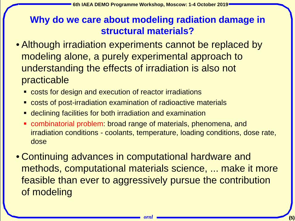
Why do we care about modeling radiation damage in structural materials?
• Although irradiation experiments cannot be replaced by modeling alone, a purely experimental approach to understanding the effects of irradiation is also not practicable costs for design and execution of reactor irradiations costs of post-irradiation examination of radioactive materials declining facilities for both irradiation and examination combinatorial problem: broad range of materials, phenomena, and
irradiation conditions - coolants, temperature, loading conditions, dose rate, dose
• Continuing advances in computational hardware and methods, computational materials science, ... make it more feasible than ever to aggressively pursue the contribution of modeling

ornl
6th IAEA DEMO Programme Workshop, Moscow: 1-4 October 2019
(6)
6th IAEA DEMO Programme Workshop, Moscow: 1-4 October 2019
(6)
Relevant phenomena with related computational and experimental methods

ornl
6th IAEA DEMO Programme Workshop, Moscow: 1-4 October 2019
(7)
6th IAEA DEMO Programme Workshop, Moscow: 1-4 October 2019
(7)
Relevance/Impact of Atomistic Mechanisms• primary damage formation – source term• point defect, solute, transmutant gas (He, H) diffusion and
agglomeration• formation and/or dissolution of precipitates• dislocation-defect interactions
These processes determine the radiation-induced microstructural evolution (mesoscale models) that lead to:• dimensional changes: void swelling, thermal and irradiation
creep, radiation growth• changes in fracture mechanisms and behavior
Continuum models, finite element models, 3D-dislocation dynamics models relate microstructure to measurable mechanical property changes
Knowledge of how to transfer information, and bridge scales and models remains critical
ornl
6th IAEA DEMO Programme Workshop, Moscow: 1-4 October 2019
(8)
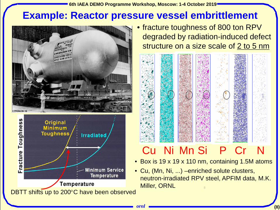
Example: Reactor pressure vessel embrittlement• fracture toughness of 800 ton RPV
degraded by radiation-induced defect structure on a size scale of 2 to 5 nm
• Box is 19 x 19 x 110 nm, containing 1.5M atoms• Cu, (Mn, Ni, ...) –enriched solute clusters,
neutron-irradiated RPV steel, APFIM data, M.K. Miller, ORNL 8
Cu Ni Mn Si P Cr N
DBTT shifts up to 200°C have been observed

ornl
6th IAEA DEMO Programme Workshop, Moscow: 1-4 October 2019
(9)
VACANCY DRAG INTERSTITIAL TRANSPORT• Vacancies can carry solute atoms along.• Occurring for Mn, Ni, Cu, P, and Si
• Interstital atoms (SIA) can couple with solute atoms and move together.
• Occurs for Cr, Mn, and P
Solute cluster formation: DFT-based kinetic models reveal that solutes in F/M (and RPV) steels are dragged by point defects
L. Messina, P. Olsson, M. Nastar, T. Garnier, C. Domain, PRB 90, 104203 (2014)
Mn, Ni, Cu, Si, and P, follow the vacancy during its migration, moreover any solute forming a mixed dumbbell (Cr, Mn & P) wil be dragged by the SIA – hence solutes segregate at point defect sinks

ornl
6th IAEA DEMO Programme Workshop, Moscow: 1-4 October 2019
(10)
DFT results implemented in OKMC model: Comparison with experimental composition of clusters
Fe-2.5%C
rFe-5%
Cr
Fe-9%C
r
𝐶𝐶𝑖𝑖 =𝐶𝐶𝑖𝑖
∑𝑘𝑘 𝐶𝐶𝑘𝑘
k = Ni, Si, P
Fe-X%Cr-Y%NiSiP irradiated at 290°C in the BR2 reactor +0.1 eV +0.3 eV +0.5 eV

ornl
6th IAEA DEMO Programme Workshop, Moscow: 1-4 October 2019
(11)
DFT results implemented in OKMC model: Comparison with experimental cluster density and size
Fe-12%Cr-0.31%NiSiP irradiated at 290°C in the BR2 reactor +0.1 eV +0.3 eV +0.5 eV
OKMC model with insights provided by DFT:• Provides reasonable agreement with key experimental results• Same model is valid for RPV and F/M steels

ornl
6th IAEA DEMO Programme Workshop, Moscow: 1-4 October 2019
(12)
6th IAEA DEMO Programme Workshop, Moscow: 1-4 October 2019
(12)
Potential effect of neutron energy spectrum differences on microstructural evolution
What is unique about the fusion environment? • generally the question assumes
DT fusion reaction, unique aspect is 14.1 MeV neutron source term
• higher energy atomic recoils for displacement damage production
• higher levels of He and H (and some solid elements) from transmutation via threshold reactions

ornl
6th IAEA DEMO Programme Workshop, Moscow: 1-4 October 2019
(13)
6th IAEA DEMO Programme Workshop, Moscow: 1-4 October 2019
(13)
Cascade damage production: Fe

ornl
6th IAEA DEMO Programme Workshop, Moscow: 1-4 October 2019
(14)
6th IAEA DEMO Programme Workshop, Moscow: 1-4 October 2019
(14)
Cascade damage production: Fe
5008001000
MD vs. NRT dpa
ornl
6th IAEA DEMO Programme Workshop, Moscow: 1-4 October 2019
(15)
6th IAEA DEMO Programme Workshop, Moscow: 1-4 October 2019
(15)
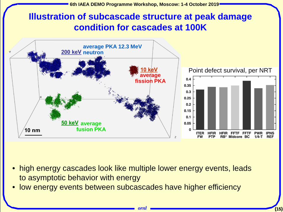
Illustration of subcascade structure at peak damage condition for cascades at 100K
• high energy cascades look like multiple lower energy events, leads to asymptotic behavior with energy
• low energy events between subcascades have higher efficiency
Point defect survival, per NRT
average fusion PKA
average fission PKA
average PKA 12.3 MeV neutron

ornl
6th IAEA DEMO Programme Workshop, Moscow: 1-4 October 2019
(16)
6th IAEA DEMO Programme Workshop, Moscow: 1-4 October 2019
(16)
Illustration of subcascade structure at peak damage condition for cascades at 100K
• high energy cascades look like multiple lower energy events, leads to asymptotic behavior with energy
• low energy events between subcascades have higher efficiency
Point defect survival, per NRT
average fusion PKA
average fission PKA
average PKA 12.3 MeV neutron
ornl
6th IAEA DEMO Programme Workshop, Moscow: 1-4 October 2019
(17)
6th IAEA DEMO Programme Workshop, Moscow: 1-4 October 2019
(17)
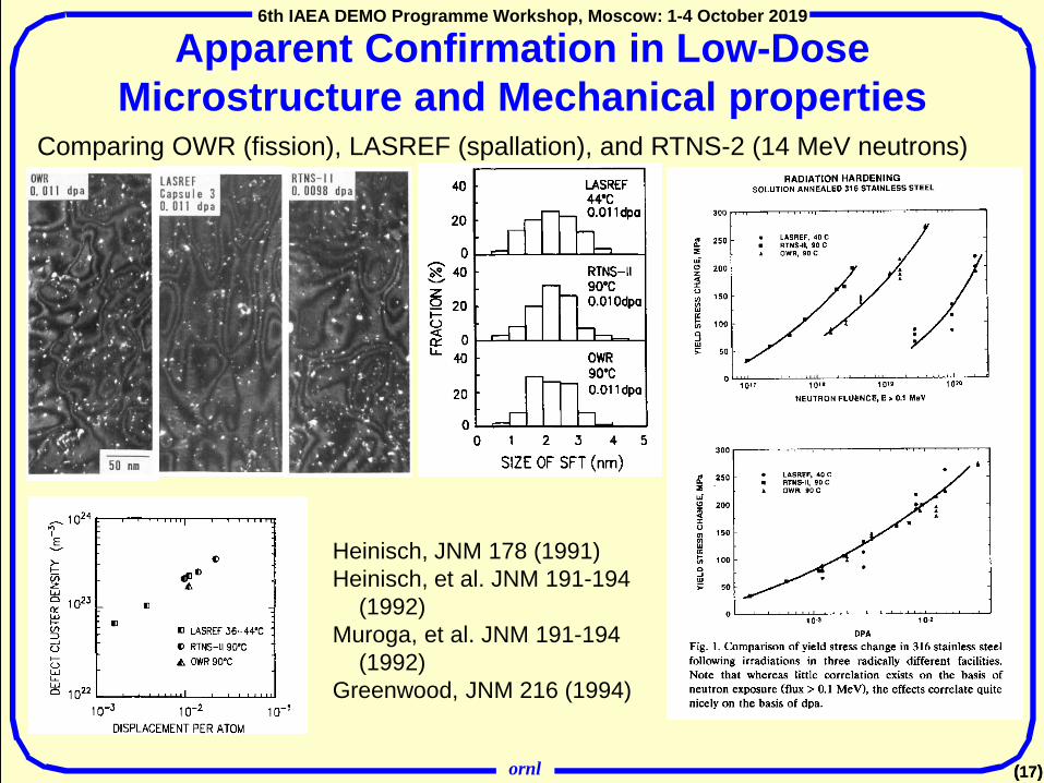
Apparent Confirmation in Low-Dose Microstructure and Mechanical properties
Comparing OWR (fission), LASREF (spallation), and RTNS-2 (14 MeV neutrons)
Heinisch, JNM 178 (1991)Heinisch, et al. JNM 191-194
(1992)Muroga, et al. JNM 191-194
(1992)Greenwood, JNM 216 (1994)

ornl
6th IAEA DEMO Programme Workshop, Moscow: 1-4 October 2019
(18)
The previously (for ~50 years) unknown mechanism of <100> interstitial loop formation in iron has been determined for the first time using the SEAKMC methodResults provide a direct link between experiments and atomistic simulations and new insights into defect evolution. − Formation process of <100> loops involves a
distinctly atomistic interaction between two ½ <111> loops.
− Reaction does not follow the conventional assumption of Burgers vector conservation between the reactants and the reaction product; process is different from all previously proposed mechanisms.
− Results observed in SEAKMC using multiple interatomic potentials and simulation cell sizes; predictions at higher temperatures could be confirmed using molecular dynamics with much greater computational effort.
Insight from self-evolving atomistic kinetic Monte Carlo (SEAKMC) method on formation of extended defects
H. Xu, et al., Phys. Rev. Let. 110 (2013)

ornl
6th IAEA DEMO Programme Workshop, Moscow: 1-4 October 2019
(19)
6th IAEA DEMO Programme Workshop, Moscow: 1-4 October 2019
(19)
Early mechanistic model and experiments used to anticipate role of transmutant helium on swelling
Impact of higher helium production in fusion than most fission environments
– austenitic stainless steels– experiments used neutron
spectrum tailoring to obtain intermediate and high helium in water moderated reactors (ORR and HFIR), c.f. low He in FFTF
– experiments confirmed model predictions of possible non-monotonic behavior
– see corresponding microstructures in Stoller, et al., JNM 155-157
Stoller, JNM 174
Though primary damage is similar, damage evolution can be influenced by a number of factors: transmutation gases, damage rate, …

ornl
6th IAEA DEMO Programme Workshop, Moscow: 1-4 October 2019
(20)
6th IAEA DEMO Programme Workshop, Moscow: 1-4 October 2019
(20)
Model Results Consistent with Earlier Dual-beam Ion Irradiation Experiements
E. A. Kenik and E. A. Lee, "Phase Stability During Irradiation," AIME Symp, AIME, New York, 1980, pp. 493-503

ornl
6th IAEA DEMO Programme Workshop, Moscow: 1-4 October 2019
(21)
Reactor-to-reactor variations in swelling observed
21
Appears related to differences in He generation due to softer neutron energy spectrum in HFIR
• Dependence of damage evolution on initial microstructure
• Complex microstructures with differences in radiation-enhanced and radiation-induced precipitates
Swelling of SA and 20%CW 316SS (DO-heat) in EBR-II (fast spectrum) and HFIR (mixed spectrum)
SA: ∆V/V greater in HFIR CW: ∆V/V greater in EBR-II

ornl
6th IAEA DEMO Programme Workshop, Moscow: 1-4 October 2019
(22)
Accelerated and alternate irradiation conditions• These, and similar, results generated considerable controversy but
highlight an important question, when is one irradiation environment an “adequate” surrogate for another?
• In order to screen materials and reach higher doses, ion irradiation has been extensively used in fast and fusion reactor materials research
• The light water reactor community has used materials test reactors to get accelerated data on RPV embrittlement, and even LWR surveillance capsules have typically been irradiated at lead factors of 3 to 10
• Useful validation of modeling results for near-term fusion devices will require the use of non-prototypical irradiation facilities – unless a proper fusion materials irradiation facility (IFMIF?) is built
Stoller on Microstructure 22

ornl
6th IAEA DEMO Programme Workshop, Moscow: 1-4 October 2019
(23)
(Partial) list of issues involved in use of different irradiation environments to understand phenomena
• neutron vs. neutron– limited range in Gdpa available– PKA spectrum effects, more modest that in ion/neutron comparison– importance of transmutation effects (He, H, some solid transmutation
• charged particle vs. neutron– a few orders of magnitude in Gdpa available– effect of surface, greater for in situ electron irradiation– effect of damage gradients– PKA spectrum– implanted ions, chemistry and interstitials– lack of transmutatation products, some can be “simulated”
• heavy ion vs. electron– PKA spectrum, lack of cascades (clusters) in electron irradiation– surface influence in electron irradiation
• neutron-neutron comparisons are least ambiguousMany of these factors work against model-experimental validation, hence can compromise use of both data and modeling for design purposes
23

ornl
6th IAEA DEMO Programme Workshop, Moscow: 1-4 October 2019
(24)
Early use of ion irradiation facilities identified effects of damage rate and helium
• Temperature and helium effects on swelling, neutrons vs. ions
Pure Ni, ~1 dpa, Gdpa=10-7 s-1 (n), 10-3 s-1 (self ions), w/ and w/o 20 appm HePackan and Farrell, JNM 78, 1978, pure nickel
24Research in both the US (ORNL) and USSR (Kharkov) identified alloy variants that were low swelling under ion irradiation but which swelled under neutron irradiation

ornl
6th IAEA DEMO Programme Workshop, Moscow: 1-4 October 2019
(25)
50µm
F82H steel Packet boundaryBlock boundary
PAG boundary
Rate theory model to investigate response of FM steel
Frenkel pair and He atoms are homogeneously produced. Formation of defect clusters in collision-cascade is neglected.
Point defects freely migrate depending on temp.
Point defects are absorbed into the dislocation sink. He atoms can dissociate thermally.
Vacancies and SIAs mutually annihilate one other.
SIAs form dislocation loops, SIAs and helium atoms can dissociate thermally
Vacancies and helium atoms form helium bubbles. Vacancies and helium atoms can dissociate thermally
Objective:The matrix of a block component of F82H (RAFM) steelReactions between defects
V
SIA(I)
He
Annihilation
neutron
Dislocation sink
Interstitial loop
DissociationHelium bubble
ornl
6th IAEA DEMO Programme Workshop, Moscow: 1-4 October 2019
(26)
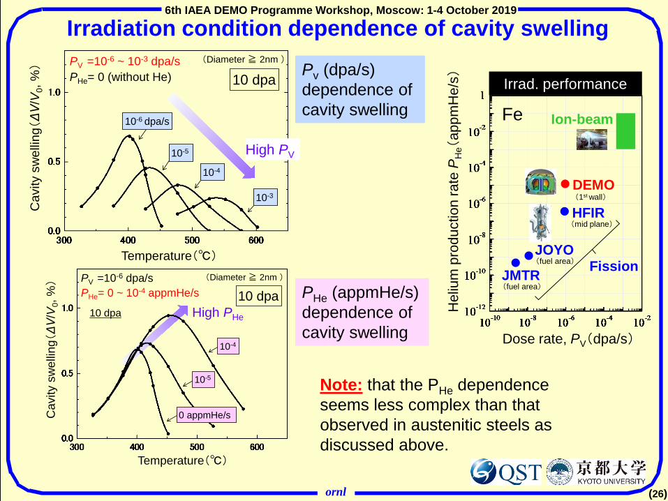
Pv (dpa/s) dependence of cavity swelling
PHe (appmHe/s) dependence of cavity swelling
Ion-beam
Hel
ium
pro
duct
ion
rate
PH
e(ap
pmH
e/s) Irrad. performance
Fe
Dose rate, PV(dpa/s)
JOYO(fuel area)
JMTR(fuel area)
Fission
DEMO(1st wall)
HFIR(mid plane)
Irradiation condition dependence of cavity swelling C
avity
sw
ellin
g(ΔV
/V0,
%)
High PV10-5
10-4
10-3
Temperature(℃)
10-6 dpa/s
10 dpa(Diameter ≧ 2nm )PV =10-6 ~ 10-3 dpa/s
PHe= 0 (without He)
10 dpa
10-4
10-5
0 appmHe/s
High PHe
PV =10-6 dpa/sPHe= 0 ~ 10-4 appmHe/s
(Diameter ≧ 2nm )
Cav
ity s
wel
ling(ΔV
/V0,
%)
Temperature(℃)
10 dpa
Note: that the PHe dependence seems less complex than that observed in austenitic steels as discussed above.
ornl
6th IAEA DEMO Programme Workshop, Moscow: 1-4 October 2019
(27)
6th IAEA DEMO Programme Workshop, Moscow: 1-4 October 2019
(27)
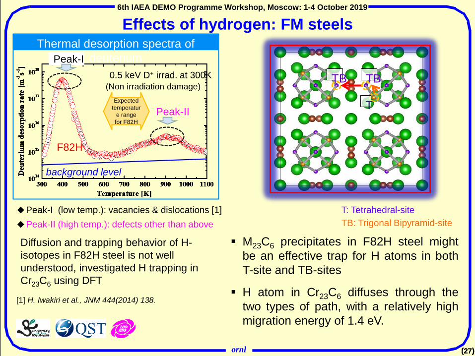
Effects of hydrogen: FM steels
Diffusion and trapping behavior of H-isotopes in F82H steel is not well understood, investigated H trapping in Cr23C6 using DFT
Peak-I (low temp.): vacancies & dislocations [1]Peak-II (high temp.): defects other than above
Thermal desorption spectra of deuteriumPeak-I
Peak-II
F82H
background level
0.5 keV D+ irrad. at 300K(Non irradiation damage)
[1] H. Iwakiri et al., JNM 444(2014) 138.
Expected temperatur
e range for F82H
TB TB
T
T: Tetrahedral-siteTB: Trigonal Bipyramid-site
M23C6 precipitates in F82H steel mightbe an effective trap for H atoms in bothT-site and TB-sites
H atom in Cr23C6 diffuses through thetwo types of path, with a relatively highmigration energy of 1.4 eV.
ornl
6th IAEA DEMO Programme Workshop, Moscow: 1-4 October 2019
(28)
6th IAEA DEMO Programme Workshop, Moscow: 1-4 October 2019
(28)
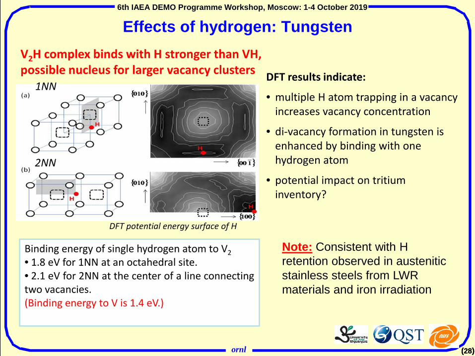
Effects of hydrogen: Tungsten
1NN
2NN
Binding energy of single hydrogen atom to V2• 1.8 eV for 1NN at an octahedral site.• 2.1 eV for 2NN at the center of a line connectingtwo vacancies.(Binding energy to V is 1.4 eV.)
DFT potential energy surface of H
V2H complex binds with H stronger than VH,possible nucleus for larger vacancy clusters DFT results indicate:
• multiple H atom trapping in a vacancy increases vacancy concentration
• di-vacancy formation in tungsten is enhanced by binding with one hydrogen atom
• potential impact on tritium inventory?
Note: Consistent with H retention observed in austenitic stainless steels from LWR materials and iron irradiation
ornl
6th IAEA DEMO Programme Workshop, Moscow: 1-4 October 2019
(29)
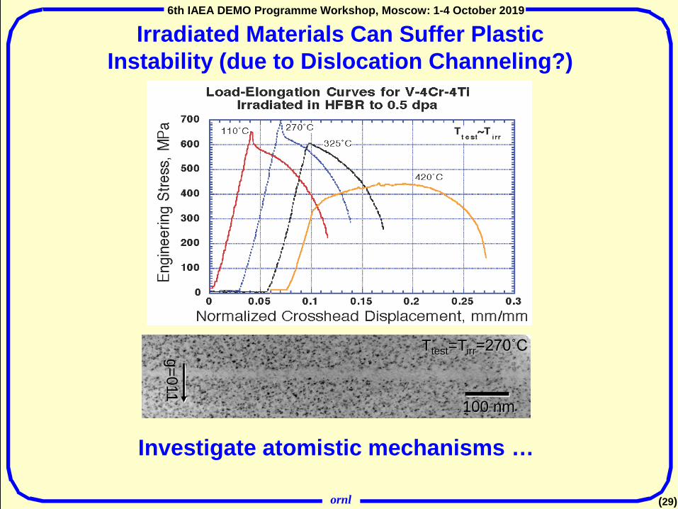
100 nm
Ttest=Tirr=270˚Cg=011
Irradiated Materials Can Suffer Plastic Instability (due to Dislocation Channeling?)
Investigate atomistic mechanisms …

ornl
6th IAEA DEMO Programme Workshop, Moscow: 1-4 October 2019
(30)
τappl = F/A • System size- few 106 mobile atoms
• Obstacle- periodic spacing L ≤100nm- size D ≤10nm - ρD ~ 1014-1015m-2
• Statics (MS) T = 0K- apply ∆ε incrementally- relax to minimum Epot- equivalent to elasticity
• Dynamics (MD) T > 0K- apply strain rate ~ 105-108 s-1,
leading to VD ~ 10-1-102 ms-1
- or apply stress
Atomistic simulations of dislocation-obstacle interaction
Obtain:• τ-ε curve (⇒ critical stress τc)• dislocation shape and impact on
obstacle structure• controlling mechanisms
Area A
Fixed
F F
L
Area A
30

ornl
6th IAEA DEMO Programme Workshop, Moscow: 1-4 October 2019
(31)
31
Void strengthening in Fe at T =0
void size
2nm (339v) void in FeL=42nm, T=0K. C1 xtal
τc ;
Gb2πL
ln 1
D −1 + L−1
+B
• voids are ‘strong’ obstacles• quantitative information on critical
stress and line shape
[line tension: τc= αGb/L ]

ornl
6th IAEA DEMO Programme Workshop, Moscow: 1-4 October 2019
(32)
• critical line shape and τc similar for D > 4nm• different for small D
- transition in τc for Cu precipitate due to dislocation-induced transformation to more stable structure; bcc to heavily twinned FCC-like (9R) structure
Cu ppts vs. voids - edge dislocation in Fe at T = 0K
• analogous results obtained for other radiation-produced defect structures such as dislocation loops, SFTs

ornl
6th IAEA DEMO Programme Workshop, Moscow: 1-4 October 2019
(33)
33
Direct comparison of MD dislocation dynamics simulation with in situ TEM experiment
Simulation and experiment reveal dynamic interaction of a gliding dislocation with stacking fault tetrahedron: critical role of free surface in experiment
Importance of simulation accurately simulating the experiment
73nm
SFT-DD movie in presentation

ornl
6th IAEA DEMO Programme Workshop, Moscow: 1-4 October 2019
(34)
Example: dislocation channeling in shearing of a Cu single crystal.
Evolution of plastic strain and SFT density shows formation of dislocation channels.
Higher level simulation: Continuum dislocation density simulation of plastic flow localization
G Po, N Ghoniem, JNM (2013).

ornl
6th IAEA DEMO Programme Workshop, Moscow: 1-4 October 2019
(35)
Discrete dislocation dynamics simulations of plastic flow localization
The model captures irradiation effects:• irradiation strengthening due to SFT density;• the main aspects of dislocation-SFT interaction;• stress induced onset of plastic instability followed by softening;• formation of localized channels with low defect density, high dislocation flux, and localized plastic distorsion.
G Po, N Ghoniem, JMPS (2014); Crisby et al, JNM (2014)
Recently, the UCLA group has started to simulate nano/micro compression tests in W using realistic dislocation mobilities for bcc metals:
Cui, Po, Marian, Ghoniem (2015)

ornl
6th IAEA DEMO Programme Workshop, Moscow: 1-4 October 2019
(36)
Microstructural domain involves micro and mesoscales
Specimen: Macroscale
A multiscale microstructural approach to ductile phase toughened tungsten structures is being developed• Tungsten-copper was used for model
development purposes• A dual-phase tungsten-copper microstructural
domain of interest from a digital image is discretized in 2D finite elements
• This domain contains copper elements embedded in tungsten elements with different assigned nonlinear material properties
• Damage, fracture, and large deformation are allowed to occur in the microstructural domain
• Homogenized tungsten-copper elastic regions connected to the microstructural domain are built to create the whole three=point bend specimen
• Adding the elastic supports and loading pin in silicon carbide completes the model
B.N. Nguyen, C.H. Henager, Jr., N.R. Overman, R.J. Kurtz J. Nuc. Mater. 508 (2018) 371
Microstructuraldomain
Modeling Ductile Phase Toughening of a Tungsten –Copper Composite - I

ornl
6th IAEA DEMO Programme Workshop, Moscow: 1-4 October 2019
(37)
Significance and impact• Different modeling scales from the micron scale to the macroscale of the
structure are effectively addressed• The model is able to capture the effects of ligaments bridging a growing crack
allowing very good predictions of damage, fracture patterns and load-displacement responses that agree with experimental results
• Capability is being further developed as a tool to tailor W-composite microstructures for optimal mechanical properties for PFC
Failure Indicator:- 0: undamaged- 1: Failed
Crack pattern in a un-notched Cu-W specimen subject to 3-point bending
Crack pattern in a Cu-W SENB specimen
Presented by: B.N. Nguyen at ICFRM-18
Modeling Ductile Phase Toughening of a Tungsten –Copper Composite - II

ornl
6th IAEA DEMO Programme Workshop, Moscow: 1-4 October 2019
(38)
Modeling the Thermal Conductivity of Unirradiated Silicon Carbide Composites
• A computational approach to thermal conductivity models of silicon carbide composites was developed and applied to modeling fusion composite materials Based on existing Eshelby-Mori-Tanaka approach (EMTA) to predict
the thermoelastic properties and thermal conductivities of fiber-reinforced composites Homogenization approach (above) based on equivalent inclusions Separate thermal conductivity values for the matrix, fibers, and coating
layer• Excellent agreement with fits to Youngblood et al.’s data as a
function of temperature Reverse-engineering allows calculations of separate effects that will
prove useful for analysis of irradiated silicon carbide composites Extremely robust method that also can capture composite mechanics in
a single framework Successfully applied to effect of irradiation (via vacancy content)
on irradiated SiC
Nguyen, B.N., F. Gao, C.H. Henager, Jr., R.J. Kurtz, JNM 448 (2014) 364.
Nguyen, B.N., C.H. Henager Jr., JNM 440 (2013) 11.

ornl
6th IAEA DEMO Programme Workshop, Moscow: 1-4 October 2019
(39)
Estimates of T-dependence of maximum operating stress: Approx. engineering predictions from composite model Fusion damage rate, φ ∼ 5x10⁻³ dpa/h Assumed damage limit (φt) of 200 dpa Time to reach damage limit ~ 40,000 h Maximum permissible strain ~ 1% Irradiation creep assumed to be athermal:
• Creep compliance ~ 0.5x10⁻⁶ (MPa-dpa)-1
• Creep-swelling coupling ~ 0.6x10⁻² dpa-1
Maximum TMS swelling at ~ 400°C S rapidly decreases at T < or > 400°C No influence of He on creep or swelling
included due to lack of quantitative data For T < ~525°C irradiation creep-swelling
limiting; thermal creep limiting at higher T Does not consider probable influence of
corrosion or creep-fatigue interaction
Phase instabilities, corrosion(?), He embrittlement(?)
Loss of toughness, ductility, He embrittlement(?) UCSB/PNNL

ornl
6th IAEA DEMO Programme Workshop, Moscow: 1-4 October 2019
(40)
Operating Temperature Windows for Structural Alloys:limited to ~300°C for most materials up to ~50 dpa
• Lower temperature limit of alloys based on radiation hardening/ fracture toughness embrittlement (K1C< ~30 MPa-m1/2)—large uncertainty for W, Mo due to lack of data
• Upper temperature limit based on 150 MPa creep strength (1% in 1000 h); chemical compatibility considerations may cause further decreases in the max operating temp.
* S.J. Zinkle and N.M. Ghoniem, Fus. Eng. Des. 51-52 (2000) 55
Thermal creep
Radiation hardeningand embrittlement
Void swelling,for some: dose, T-dependent
Can we improve or replace materials?

ornl
6th IAEA DEMO Programme Workshop, Moscow: 1-4 October 2019
(41)
6th IAEA DEMO Programme Workshop, Moscow: 1-4 October 2019
(41)
Improved Nuclear Materials Are Driven By Modern Materials Science
Basic ScienceApplied R&D
Enable Improved Performance and Advanced DesignsComputational
Thermodynamics
Mechanistic Understanding
Improved materials performance enables advanced designs and capital cost reductions
Advanced Characterization Tools
Radiation Damage Fundamentals
Improved performance knowledge increases reliability in all types of reactors
Advance Manufacturing and Alloy Design
0
200
400
600
800
1000
1200
0 0.05 0.1 0.15 0.2 0.25 0.3 0.35
USJF82Hss2
Engi
neer
ing
Stre
ss, M
Pa
Engineering Strain, mm/mm
Unirradiated YS
200°C/10 dpa250°C/3 dpa
300°C/8 dpa
400°C/10 dpa
400°C/34 dpa
500°C/8 dpa
500°C/34 dpa
600°C/8 dpa
Tirr=Ttest

ornl
6th IAEA DEMO Programme Workshop, Moscow: 1-4 October 2019
(42)
6th IAEA DEMO Programme Workshop, Moscow: 1-4 October 2019
(42)
Materials Development time: Example
ATI AlllVac in Advanced Materials & Processes (2006)
However, what degree of material improvement is practicable on the timescale fusion DEMO and beyond?
e.g. 55oC improvement in upper operating temperature limit after 40 years ofdevelopment

ornl
6th IAEA DEMO Programme Workshop, Moscow: 1-4 October 2019
(43)
6th IAEA DEMO Programme Workshop, Moscow: 1-4 October 2019
(43)
Three Relevant Questions for DEMO-like Programs/Designers
1) What risks are your funders willing to undertake?2) What will your regulator require for licensing?3) What can modeling provide to help address the first
two questions?
The first question is above my paygrade, but suggests a a related question: what risks (i.e. of failure) is the fusion community willing to take?
I have some thoughts and comments on (2) and (3)

ornl
6th IAEA DEMO Programme Workshop, Moscow: 1-4 October 2019
(44)
6th IAEA DEMO Programme Workshop, Moscow: 1-4 October 2019
(44)
What will the national regulator(s) require?
• In a general sense, one can expect that they will require minimal (near zero) risk of injury to any member of the public under any conceivable (broadly defined to include what seems nearly unconceivable) accident
• Although fusion has some significant advantages over fission:− most severe accident consequences are much lower, but some accident
scenarios have the possibility of offsite impact− the waste stream does not contain long-lived fission products or actinides, but
fusion will have a significant radioactive waste stream• Fusion power plants can expect serious regulatory scrutiny once the realistic
possibility exists of a high-duty-cycle DT machine, i.e. one well beyond ITER• The available, so-called reduced-activation materials will not prevent attention to
the waste issue• One can expect that choice of pressure boundary materials and safety-related
structural materials will be subject to current design codes (next few slides)• Other materials critical to plant operations and control (superconducting
materials, dielectric materials, …) may see less scrutiny from regulators, but may be of more concern from the standpoint of a risk to capital

ornl
6th IAEA DEMO Programme Workshop, Moscow: 1-4 October 2019
(45)
6th IAEA DEMO Programme Workshop, Moscow: 1-4 October 2019
(45)
Example: Approval of new material for pressure boundary in ASME Code (only in part)
The following information must be submitted to the BPV Committee:• the Section or Sections and Divisions of the Code in which the new material is to
be approved• the temperature range of intended application• whether cyclic service is to be considered• whether external pressure is to be considered• identify all product forms, size ranges, and specifications or specification
requirements for the material for which approval is desired. • When available, describe service experience in the temperature range
requested.For all mechanical properties, data shall be provided over the required range of test temperatures from at least three heats of material meeting all of the requirements of the applicable specifications. • For time-independent properties at and above room temperature, the required
data include values of ultimate tensile strength, 0.2% offset yield strength …, reduction of area, and elongation, at 100°F intervals, from room temperature to 100°F above the maximum intended use temperature.
• For time-dependent properties , … data, as itemized below, shall be provided, starting at temperatures approximately 50°F below the temperature where time-dependent properties may govern and extending at least 100°F above the maximum intended use temperature.

ornl
6th IAEA DEMO Programme Workshop, Moscow: 1-4 October 2019
(46)
6th IAEA DEMO Programme Workshop, Moscow: 1-4 October 2019
(46)
More on ASME code qualification• For time-dependent properties , … data, as itemized below, shall be provided,
starting at temperatures approximately 50°F below the temperature where time-dependent properties may govern and extending at least 100°F above the maximum intended use temperature. it may be necessary to choose different temperature intervals in order to
adequately reflect the evolution of the properties. In such cases, the interval between successive test temperatures shall be chosen such that rupture lives do not differ by more than a factor of 10 at any given stress for two adjacent temperatures. Data to be reported include stress, temperature, time to rupture, and, when available, either or both elongation and reduction of area.
Except as provided further below, the longest rupture time at each test temperature shall be in excess of 10,000 hr for each required heat. At least three additional tests shall be conducted for each required heat at each test temperature, at stresses selected to provide shorter rupture times but at least 500 hr (e.g., 500 hr, 1,400 hr, and 4,000 hr).
For new materials for which the expectation of reasonable stability of strength-controlling microstructures is uncertain or suspect, and for extension of allowable stresses of more familiar classes of alloys into much higher temperature applications where such stability might come into question, either creep rupture data with duration of more than 30,000 hr or equivalent experience in service is required.

ornl
6th IAEA DEMO Programme Workshop, Moscow: 1-4 October 2019
(47)
6th IAEA DEMO Programme Workshop, Moscow: 1-4 October 2019
(47)
More on ASME code qualification• Test methods employed … shall be … the appropriate ASTM test methods, recommended
practices, or test methods described in accepted international standards.
SS-J3 tensile specimen, dimensions in mm
Typical HFIR Target “rabbit” Capsule and small tensile specimen
Typical Standard Test Specimen, ASTM E8Significant size reduction compared to traditional standard specimen:
• G=50 mm, c.f. 5 mm• L=200mm, c.f. 16 mm• T=16 mm, c.f. 0.75 mm
Note: small tensile contains ~3x10²¹ atoms, c.f. “large” MD simulation with <109 atoms

ornl
6th IAEA DEMO Programme Workshop, Moscow: 1-4 October 2019
(48)
6th IAEA DEMO Programme Workshop, Moscow: 1-4 October 2019
(48)
More on specimen size: Fracture touchness
10 mm x 4.6 mm
50.8 cm x 50.8 cm x 20.3 cm
“master curve” approach enables valid tests from smaller specimens due to statistical treatment of probability of crack encountering local brittle regions – weak link
ornl
6th IAEA DEMO Programme Workshop, Moscow: 1-4 October 2019
(49)
6th IAEA DEMO Programme Workshop, Moscow: 1-4 October 2019
(49)
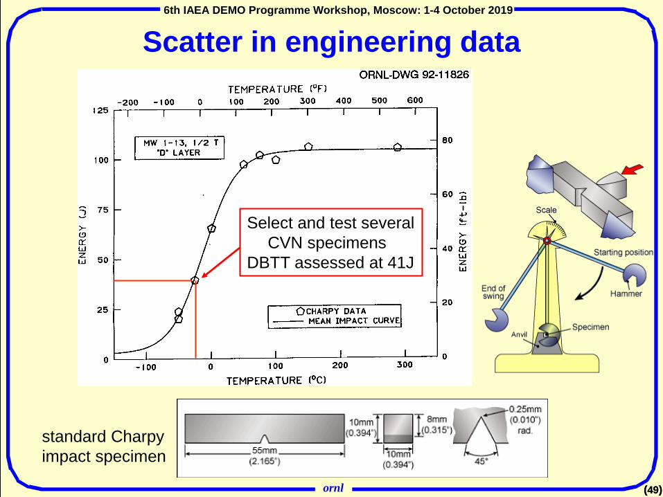
Scatter in engineering data
Select and test several CVN specimens
DBTT assessed at 41J
standard Charpy impact specimen

ornl
6th IAEA DEMO Programme Workshop, Moscow: 1-4 October 2019
(50)
6th IAEA DEMO Programme Workshop, Moscow: 1-4 October 2019
(50)
Scatter in engineering data
Select and test several CVN specimens
DBTT assessed at 41J
standard Charpy impact specimen
All CVN data from Midland vessel welds ORNL-6740
uncertainty at 41J ~53°C
ornl
6th IAEA DEMO Programme Workshop, Moscow: 1-4 October 2019
(51)
6th IAEA DEMO Programme Workshop, Moscow: 1-4 October 2019
(51)
What/how can modeling provide to help address material qualification and reliability?
• examples given above illustrate that modeling can identify critical processes and mechanisms that contribute to radiation-induced property changes
• effects of alloy chemistry and microstructure can largely be accounted for in models from the atomistic to the mesoscale
• micromechanical models can provide guidance on probable failure mechanisms – but must account for specimen size/volume effects, mechanisms determined by “weakest-link”
• microstructure-mechanical property correlations – heavily guided by experiments – can provide some predictive capability for anticipating component failure conditions (temperature, applied stress, time/fluence …)
• well-calibrated mesoscale models using an appropriate database can provide a basis for extrapolating beyond existing databases (fluence, He/dpa ratio, …)
However, modeling alone is unlikely to be sufficient to replace data from experiments in representative irradiation environments, particularly in regulatory space
A combination of modeling and fission/ion irradiations can help guide use of fusion neutron source, screen and select candidate materials

ornl
6th IAEA DEMO Programme Workshop, Moscow: 1-4 October 2019
(53)
53
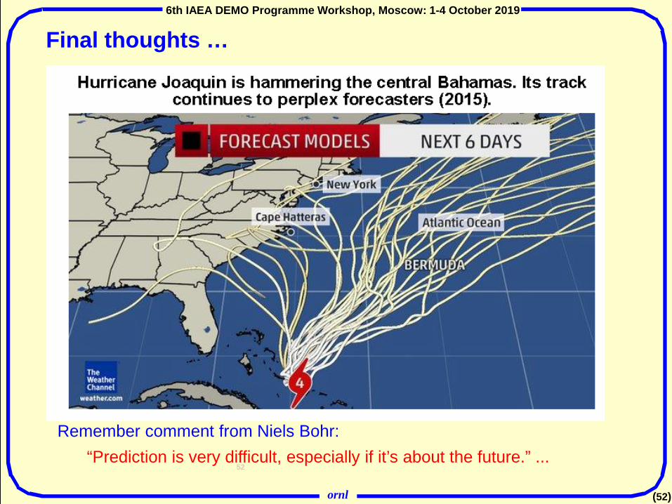
Final thoughts …
• Recall a little history- first fission reactors (Chicago pile in1942 and ORNL graphite reactor in1943) were built using a few slide rules, a good understanding of relevant (and then current) physics, and good physical intuition
- mistakes are easily made when computer models are believed too much, i.e. in the absence of: good physical intuition knowledge (and acknowledgement) of model limitations broad familiarity with relevant experimental data
• Unless (and even if) you are Fermi, be a bit skeptical of your computational results
Remember comment from Niels Bohr:“Prediction is very difficult, especially if it’s about the future.” ...
ornl
6th IAEA DEMO Programme Workshop, Moscow: 1-4 October 2019
(52)
52
Final thoughts …
• Recall a little history- first fission reactors (Chicago pile in1942 and ORNL graphite reactor in1943) were built using a few slide rules, a good understanding of relevant (and then current) physics, and good physical intuition
- mistakes are easily made when computer models are believed too much, i.e. in the absence of: good physical intuition knowledge (and acknowledgement) of model limitations broad familiarity with relevant experimental data
• Unless (and even if) you are Fermi, be a bit skeptical of your computational results
Remember comment from Niels Bohr:“Prediction is very difficult, especially if it’s about the future.” ...