7028fchnewswglit - the home depot maximum equivalent horizontal pipe length (feet)
TRANSCRIPT
V E N T I N G G U I D E
w w w . f i e l d c o n t r o l s . c o m
May 2007

3
SWG Power Venter
Gas and oil heating appliances generate heat throughthe combustion of fuel. The heat is transferred throughthe heat exchanger and distributed to the conditionedspace. The products of combustion, however, must bevented safely out of the structure. In a conventionalchimney, venting is achieved by the natural lifting actionof the hot combustion gas. New, efficient systems absorbmore of the heat in the heat exchanger and producelower temperature vent gas. Lower temperature gasdoes not rise as quickly or as reliably as in older, lessefficient systems. Power venting or sidewall venting ismore economical and safer than chimney venting. Apower venter uses a motorized blower to vent theproducts of combustion. A power venter is interlockedwith the appliance to ensure that proper draft isachieved before the appliance burner is activated.
The SWG Power Venter is the safest, mostefficient power venter available today.
Patented SWG Power Venters are ETL and cETL listedfor all LP gas, natural gas, or oil-fired heatingequipment. The SWG combines the motor, blower,and vent hood in one complete, easy to install unit.The SWG mounts on the outside of the building andpulls the combustion gases from the appliancethrough the outside wall utilizing 100% negativepressure.
Benefits of the SWG Power Venter include:
• 100% negative pressure in the vent pipe formaximum safety.
• Standard galvanized pipe can be used instead ofexpensive stainless steel.
• No need to seal vent pipe joints, saving time andmoney.
• Significantly longer vent lengths than positivepressure, direct vent systems.
• The SWG is recommended by major heatingappliance manufacturers.
The SWG must be sized to match the appliance orappliances input firing rate. Most firing rates arepublished in the manufacturer’s installation manual.SWGs must be installed with a CK Control Kit toensure proper listing and safe, efficient venting.
How the SWG Works
When to use the SWG:• Use with gas or oil furnaces, boilers, and water heaters.• New construction.• When converting from electric to gas or oil.• To avoid relining a chimney.• When installing an additional heating appliance.• When co-venting a water heater with a furnace.
1. The thermostat calls for heat, energizing thePower Venter (A).
2. A negative pressure is created, closing thepressure switch on the control kit (B).
3. The burner (C) is activated and combustion gasesare exhausted (D).
4. After the thermostat is satisfied, the burner shutsdown and the venter continues to post purge,exhausting residual flue gases.
5. When the timer or temperature control is satisfied,the venter is deactivated.
Replacement Motor Kit and Stainless Steel Model shown.
Note: SWG-4HD, 5 & 6 Motor Kits include a stainless steelblower wheel for better performance and extended life.
(Outdoor Mounted PowerVenters for Oil & Gas)
NEW SWG Power V enter
Supplemental air through Draft Control
The SWG pulls combustion gases to the outside, creating 100% negative pressur ein the vent pipe.
A
D
B
C

4
SWG Power Venter(Outdoor Mounted PowerVenters for Oil & Gas)(Sizing The Venter)
NOTE: Control Kits are required for operation of the SWG. Stainless steel recommended for oil applications.
Size the SWG venter based on the input firing rate of theappliance. If the power venter is being used to ventmultiple appliances, add the input firing rates for eachappliance and use that total to size the venter. Knowingthe total input BTU/hr. for gas, or GPH for oil, the ventercan be sized from Table 1. Select the venter rated closestto the total input BTU or GPH for installation. If the inputof the appliance is higher than the max allowable forthat size SWG, move to the next larger size SWG.
Do not select a venter with a maximum BTU/hr. or GPHlower than the appliance.
The equivalent feet of vent pipe for the installation mustbe calculated. Based on the vent pipe diameter to beused, compare the calculated equivalent feet of vent pipewith the maximum equivalent feet allowable for theventer (see Table 1). If the calculated equivalent feet isgreater than that allowed for the venter, increase thediameter of the vent pipe to be used and refer to thetable or use the next larger size SWG venter.
Table 2 - Specifications
Sizing The Venter Table 1 - Use Maximum BTU or GPH Input
“s” Designates stainless steel model.
* Oil: Select venter according to theactual rated maximum GPH input.SWG GPH ratings at 100 psi. Donot exceed maximum oil GPH input.
** Gas: Do not exceed maximumBTU/hr. input rating. For multipleventing system applications add theinput for each appliance. CategoryIII gas-fired draft induced systemsrequire an SWG-5 or larger.Unit sizing may vary depending onspecific application. Consult yourdealer or factory representativefor the proper sizing for yourparticular application.
Model Volts Hz Amps Watts RPMThermalProtect. A B C D E F
SWG-3 115 60 0.6 40 3000 YES 3" 5" 9 1⁄16" 8 1⁄2" 7 5⁄8" 9 3⁄16"
SWG-4HD 115 60 1.7 138 3000 YES 4" 6" 11 3⁄4" 9 1⁄2" 9" 9"
SWG-4HDs 115 60 1.7 138 3000 YES 4" 6" 11 3⁄4" 9 1⁄2" 11" 11 1⁄2"
SWG-5 115 60 1.3 144 3100 YES 5" 7" 11 3⁄4" 10 3⁄4" 12" 12 1⁄4"
SWG-5s 115 60 1.3 144 3100 YES 5" 7" 11 3⁄4" 10 1⁄2" 12" 12 1⁄2"
SWG-6 115 60 2.1 228 3100 YES 6" 8" 11 3⁄4" 10 3⁄4" 12" 12 1⁄4"
SWG-6s 115 60 2.1 228 3100 YES 6" 8" 11 3⁄4" 10 1⁄2" 12" 12 1⁄2"
SWG-8 115 60 4.37 478 3100 YES 8" 10" 11 3⁄4" 11 7⁄8" 13" 14 1⁄4"
SWG-10 115/230 60 11.4/5.7 1311 1725 YES 10" 14" 19 1⁄2" 24" 20" 21"
SWG-12 115/230 60 13.6/6.8 1564 1725 YES 12" 16" 19 1⁄2" 25" 22" 23"
SWG-14 115/230 60 14.0/7.0 1610 1725 YES 14" 18" 19 1⁄2" 26" 24" 25"
MODELMAX*
OIL GPHINPUT100psi
MAX*OIL GPHINPUT140psi
MAX**GAS BTU/hr.
INPUT
Maximum Equivalent Feet of Vent Pipe VENTPIPE SIZEAT MAX
BTU/hr. INPUTAT 60% OF MAXBTU/hr. INPUT
SWG-3 N/A N/A 70,000 21 80 3"50 100 4"
SWG-4HD, 4HDs 1.10 .90 170,00035 100 4"65 100 5"100 100 6"100 100 7"
SWG-5, 5s 1.85 1.55 290,00016 44 4"51 100 5"95 100 6"100 100 7"
SWG-6, 6s 2.65 2.25 416,00028 78 5"68 100 6"100 100 7"
SWG-8 4.75 4.0 740,00026 72 7"51 100 8"70 100 9"
SWG-10 9 7.5 1,300,00010 100 8"30 100 10"75 100 12"
SWG-12 13.5 11.5 1,900,00016 100 10"40 100 12"86 100 14"
SWG-14 21 17.75 3,000,0008 85 12"18 100 14"35 100 16"
Note: In Table 1, the maximum equivalent footage allowablefor the vent pipe is given for two points, the maximum BTU/hr.venting capacity and at 60% of the maximum. This allows forestimating values between the two given points.
5
SWG Power Venter
To calculate the footage, add the lengths of all the straightlengths of vent pipe to the equivalent feet of all the vent pipefittings, such as tees, elbows, and reducers.
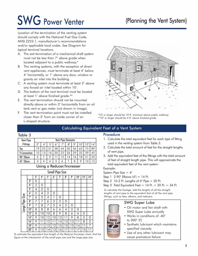
Procedure1. Calculate the total equivalent feet for each type of fittingused in the venting system from Table 3.
2. Calculate the total amount of feet for the straight lengthsof vent pipe.
3. Add the equivalent feet of the fittings with the total amountof feet of straight length pipe. This will approximate thetotal equivalent feet of the vent system.
Example:System Pipe Size = 4"Step 1 2-90° Elbows (4") = 14 Ft.Step 2 10-2 Ft. Lengths of 4" Pipe = 20 Ft.Step 3 Total Equivalent Feet = 14 Ft. + 20 Ft. = 34 Ft.
To estimate the equivalent foot length of the Reducer/Increaser chart, find thefigure at the intersection of the small pipe size and the large pipe size.
Table 3
Calculating Equivalent Feet of a Vent System
*10" or larger should be 10 ft. minimum above public walkway.**10" or larger should be 4 ft. above finished grade.
(Planning the Vent System)
Using a Reducer/Increaser
Small Pipe Size3" 4" 5" 6" 7" 8" 9" 10" 12" 14"
3" 04" 2 05" 4 2 06" 5 4 2 07" 6 5 4 1 08" 7 7 6 3 2 09" 7 8 7 5 4 2 010" 8 8 8 6 6 4 2 012" 8 10 10 8 9 8 6 4 014" 9 10 12 10 12 11 9 8 3 016" 9 11 12 11 14 13 13 11 8 318" 9 11 13 12 15 15 15 14 11 720" 9 12 14 13 16 17 17 17 15 11
Larg
ePipe
Size
Vent PipeFittings
Vent Pipe Diameter3" 4" 5" 6" 7" 8" 9" 10" 12" 14"
Tee 19 25 31 38 44 50 56 63 75 89
Y-Connection 10 13 16 20 23 26 29 32 39 45
90° Elbow 5 7 9 11 12 14 16 18 21 25
45° Elbow 3 4 4 5 6 7 8 9 10 13
Location of the termination of the venting systemshould comply with the National Fuel Gas Code,ANSI Z223.1, manufacturer’s recommendationsand/or applicable local codes. See Diagram fortypical terminal locations.A. The exit termination of a mechanical draft system
must not be less than 7’ above grade whenlocated adjacent to a public walkway.*
B. The venting systems, with the exception of directvent appliances, must terminate at least 4’ below,4’ horizontally, or 1’ above any door, window orgravity air inlet into the building.
C. A venting system must terminate at least 3’ aboveany forced air inlet located within 10’.
D. The bottom of the vent terminal must be locatedat least 1’ above finished grade.**
E. The vent termination should not be mounteddirectly above or within 3’ horizontally from an oiltank vent or gas meter (not shown in image).
F. The vent termination point must not be installedcloser than 3’ from an inside corner of anL-shaped structure.
• Oil motor and fan shaft withSWG Super Lube annually
• Works in conditions of -40°to 300° (F)
• Synthetic lubricant which maintainsspecified viscosity
• Use of any other lubricant maycause premature failure
SWG Super Lube

6
SWG Power Venter (Clearance to Combustibles)
If mounting the venting system near combustiblematerials, refer to Diagram A for allowable installationclearances. Clearances are based on an installationusing single wall galvanized steel vent pipe. Ifmanufactured double wall vent pipe is required or usedfor the installation, clearance should be based on thevent pipe’s rated clearance. Always check local coderequirements for code restrictions.
Routing of the vent system and clearances for the ventpipe may be planned once the termination location isdetermined. Route the vent pipe from the appliance tothe venter using as few elbows as possible. Thehorizontal section of the vent pipe should have a slightupward slope from the appliance to the venter. The ventpipe size (diameter) can be smaller than a typicalchimney vented system and still overcome the higherpressure losses because the power venter mechanicallycreates the required draft or air flow to vent the system.
For estimating the minimum vent pipe diameter for agas system, divide the BTU/hr. input of the heatingequipment by 12,600 BTU/sq. in. For oil systems,multiply GPH by 140,000BTU/GAL, then divide by12,600 BTU/sq. in. This willgive the minimum crosssectional area required. (SeeTable 4 for area to diameterconversion.) For multipleequipment venting systems,divide the total BTU/hr. inputfor all appliances by 9,300BTU/sq. in. This will give youthe minimum vent pipediameter needed for thecommon breaching of thevent system.
As a rule of thumb, size the vent pipe to the outletdiameter of the heating equipment for a singleappliance venting system. For multiple applianceventing systems, use the outlet diameter of the largestunit and add 50%.
* With galvanized sheet metal liner or equivalent
Single Pipe System Double Pipe System
Extension Kits
Diagram A
Pipe SizeNominal
Cross-SectionalArea Sq. Inches
3" 74" 135" 206" 287" 388" 509" 6410" 7912" 11314" 154
Table 4
PowerVenterModel
ExtensionKit Model
SWG-4HD PEK-4SWG-4HDS PEK-4SWG-5 PEK-5SWG-5S PEK-5SWG-6 PEK-6SWG-6S PEK-6SWG-8 PEK-8
Allowable InletTemperature
Clearance(B)
400ºF or Less 3" min.550ºF or Less 4" min.550ºF or Less 3" min.*
Allowable InletTemperature
Clearance(A)
400ºF or Less .5" min.550ºF or Less 1" min.550ºF or Less .5" min.*
The standard SWG Power Venter is designed for walls up to 8" thick. PEK extensionkits allow the SWG to be installed in walls up to 16" thick.* The PEK kit includes theinner/outer pipe extension, air flow damper, and one foot of 1/4" aluminum tubing.It is available for models SWG-4HD through SWG-8.
* PEK-4 allows the SWG to be installed in walls up to 12" thick.

7
Control Kits(Required to Operate SWG Power
Venters and Draft Inducers)
CK-61 All oil-fired systems. Has adjustable electronic post purge. � � � �
CK-62 All oil-fired systems. Has thermally activated post purge. � � � �
CK-63 All oil-fired systems. (May require optional delay oil valve forsimultaneous burner operation.)
� � �
CK-20FVCK-20FG
30 millivolt gas-fired water heaters and gas-fired pool orspa heaters with a manual or internally mounted thermostat.
� � �
CK-21 Gas-fired instantaneous water heaters with pressure tap portin the burner manifold.
� �
CK-41FCK-41P**
Furnaces, boilers, unit heaters and water heaters operating with a24 VAC gas valve without factory mounted spillage switches.
� � �
CK-43 Draft induced 24 VAC gas valve systems. Includes a 4' MG-1draft control and post purge.
� � �
CK-43F � � �
CK-81***750 millivolt operated boilers, furnaces, water heaters, pool or spaheaters and gas-fired fireplaces when operated with a remote mountedthermostat or on/off switch. Operated off a 24 VAC circuit.
� �
CK-91FVCK-91FG
Gas-fired draft induced 24 VAC gas valve systems and a 30 millivoltoperated water heater. Includes a 4' MG-1 draft control and post purge.
� � � � �
CK-92FVCK-92FGCK-92FVP**CK-92FGP**
Gas-fired furnace or boiler and a 30 millivolt operated water heater.Includes post purge.
� � � �
30m
vCo
-ven
ting
Multi
pleAp
plian
ces
24v
750m
v
Draf
tPro
ving
Switc
h
GasP
ressu
reSw
itch
Seco
ndar
ySaf
etySw
itch
Ther
mal
Post
Purg
e
Adjus
table
Electr
onic
Post
Purg
e
Fixed
Post
Purg
e
Draf
tCon
trol
* Control Kits are ETL approved accessories when used in conjunction with the SWG Power Venter.** Plugs into 24v electric damper*** A secondary safety switch should be used with a CK-81F = Fixed Post Purge FV= right hand threaded TCA Safety Switch FG= left hand threaded TCA Safety Switch
CK-41F mounted at venter. For use with a 24 VAC,gas-fired system (shown with cover off).
CK-63 remote mounted. For use with 120 VAC oil-fired systems.Electronic post purge is included (shown with cover off).
Control Kit InstallationRJ
R-6
ApplicationsControl Kit*
Control Kits (CK) control the operation of SWG PowerVenters. See the chart below to select the proper kit foryour application. Control Kits can also control theoperation of Field Draft Inducers.
CK kits can be mounted up to 100 feet from venter.
Oil
Gas
8
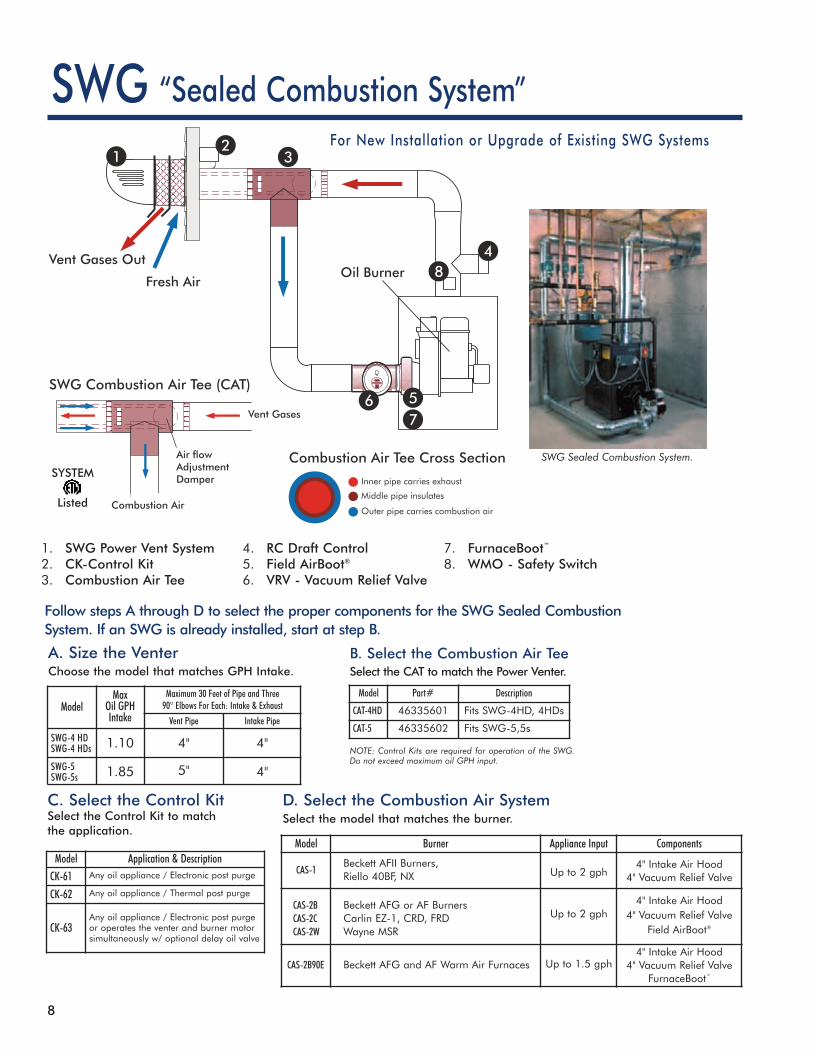
SWGFor New Installation or Upgrade of Existing SWG Systems
“Sealed Combustion System”
SYSTEM
Listed
SWG Sealed Combustion System.
B. Select the Combustion Air TeeSelect the CAT to match the Power Venter.
NOTE: Control Kits are required for operation of the SWG.Do not exceed maximum oil GPH input.
A. Size the VenterChoose the model that matches GPH Intake.
Model Part# Description
CAT-4HD 46335601 Fits SWG-4HD, 4HDs
CAT-5 46335602 Fits SWG-5,5s
ModelMax
Oil GPHIntake
Maximum 30 Feet of Pipe and Three90° Elbows For Each: Intake & Exhaust
Vent Pipe Intake Pipe
SWG-4 HDSWG-4 HDs 1.10 4" 4"
SWG-5SWG-5s 1.85 5" 4"
1. SWG Power Vent System2. CK-Control Kit3. Combustion Air Tee
4. RC Draft Control5. Field AirBoot®
6. VRV - Vacuum Relief Valve
7. FurnaceBoot™
8. WMO - Safety Switch
C. Select the Control KitSelect the Control Kit to matchthe application.
D. Select the Combustion Air SystemSelect the model that matches the burner.
Follow steps A through D to select the proper components for the SWG Sealed CombustionSystem. If an SWG is already installed, start at step B.
Model Burner Appliance Input Components
CAS-1Beckett AFII Burners,Riello 40BF, NX Up to 2 gph
4" Intake Air Hood4" Vacuum Relief Valve
CAS-2BCAS-2CCAS-2W
Beckett AFG or AF BurnersCarlin EZ-1, CRD, FRDWayne MSR
Up to 2 gph4" Intake Air Hood
4" Vacuum Relief ValveField AirBoot®
CAS-2B90E Beckett AFG and AF Warm Air Furnaces Up to 1.5 gph4" Intake Air Hood
4" Vacuum Relief ValveFurnaceBoot™
Model Application & DescriptionCK-61 Any oil appliance / Electronic post purge
CK-62 Any oil appliance / Thermal post purge
CK-63Any oil appliance / Electronic post purgeor operates the venter and burner motorsimultaneously w/ optional delay oil valve
9
SWG
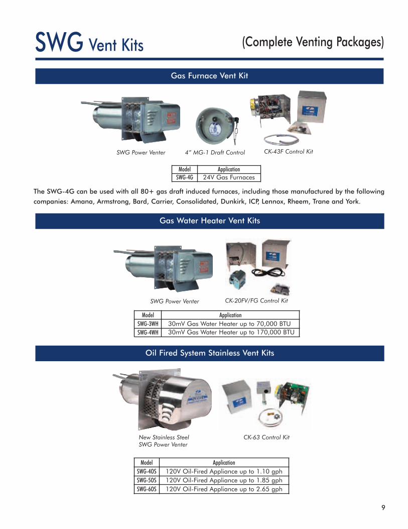
The SWG-4G can be used with all 80+ gas draft induced furnaces, including those manufactured by the following
companies: Amana, Armstrong, Bard, Carrier, Consolidated, Dunkirk, ICP, Lennox, Rheem, Trane and York.
SWG Power Venter
SWG Power Venter CK-20FV/FG Control Kit
New Stainless SteelSWG Power Venter
4” MG-1 Draft Control
CK-63 Control Kit
CK-43F Control Kit
Gas Furnace Vent Kit
Gas Water Heater Vent Kits
Oil Fired System Stainless Vent Kits
(Complete Venting Packages)
Model ApplicationSWG-4G 24V Gas Furnaces
Model ApplicationSWG-3WH 30mV Gas Water Heater up to 70,000 BTUSWG-4WH 30mV Gas Water Heater up to 170,000 BTU
Model ApplicationSWG-4OS 120V Oil-Fired Appliance up to 1.10 gphSWG-5OS 120V Oil-Fired Appliance up to 1.85 gphSWG-6OS 120V Oil-Fired Appliance up to 2.65 gph
Vent Kits

10
PV
Co-venting: Use CK-20FV/FG
How PV Series Venters Work
MG-1
CK-20FV/FG
(Indoor Mounted PowerVenters for Oil & Gas)Power Venters
SWH
Accessories
1. Thermostat or aquastat calls for heat and starts thePower Venter.
2. The Pressure Switch senses sufficient air flow andallows burner(s) to start.
3. The Power Venter draws combustion air through thesystem and forces gases outside through an externalVent Hood.
4. Draft Hood or Barometric Draft Control between theappliance(s) and the Power Venter maintainsconsistent air flow.
5. After the thermostat is satisfied, the burner shutsdown and the Post Purge Control clears the ventingsystem of combustion gases.
6. The Power Venter shuts down.
The indoor mounted PVG and PVO PowerVenters provide an economical power ventingsystem for gas and oil appliances. All controlsare built into these units. A Vent Hood is requiredto terminate the vent system.
SWH Vent HoodsDesigned for standard vent pipe and Class B type double-wall (B-Vent) connection. Provides proper clearance between flue gasstream and wall combustibles. Available in 3" through 8" sizes.
MG-1 Series Draft ControlRequired for 80+ draft induced system applications. Available in4" through 9" sizes.
CK-20FV/FG Water Heater Control(Required for co-venting residential water heaters.)Provides all system control components required to utilize the FieldPower Venter with natural gas or LP gas millivolt water heater,including safety interlock controls. This kit allows you to co-vent aresidential water heater with a furnace or boiler.

11
PV (Indoor Mounted PowerVenters for Oil & Gas)
PVG - Gas and PVG PAK
Maximum Equivalent Horizontal Pipe Length (Feet)†
Model(BTU/hr Input)
DIA. 25,000 55,000 70,000 100,000 145,000 220,000 310,000 400,000 520,000 610,000 900,000 1,250,000
PVG-100PVGPAK-100*
3" 270 100 – – – – – – – – – –
4" 455 169 144 100 – – – – – – – –
PVG-300PVGPAK-300*PVU-300
4" – – – 305 145 64 – – – – – –
5" – – – – 247 100 54 – – – – –
6" – – – – 334 147 74 – – – – –
PVG-6005" – – – – 413 181 91 54 – – – –
6" – – – – – – 146 87 52 – – –
8" – – – – – – 216 134 86 66 – –
PVE-1200**8" – – – – – – – – – 313 180 –
10" – – – – – – – – – 390 290 80
PVO - Oil
Maximum Equivalent Horizontal Pipe Length (Feet)†
Model DIA.GPH Input
0.40 0.50 0.75 1.00 1.50 2.25 3.00 3.75 4.00 6.00 9.00
PVO-300PVU-300
4" – – 287 150 75 – – – – – –
5" – – – 257 120 51 – – – – –
6" – – – 346 172 70 – – – – –
PVO-6005" – – – 428 212 86 46 – – – –
6" – – – – – 143 74 51 – – –
8" – – – – – 211 116 84 77 – –
PVE-1200*8" – – – – – – – 436 385 208 –
10" – – – – – – – – 407 311 74
Power Venters
† See calculating equivalent feet of a vent system* PVG PAKs include a Power Venter, a 4" MG-1 Draft Control, and a 4" Vent Hood.** PVE-1200 requires a CK-Kit.
WD
H
Specifications
† See calculating equivalent feet of a vent system* PVE-1200 requires a CK-Kit.Select venter according to the actual rated maximum GPH Input. GPH ratings at 100 PSI.Do not exceed maximum oil GPH Input.
UNIT DIMENSIONS (INCHES) ELECTRICAL DATA
Model Height Width Depth Inlet/Outlet Volts Hz RPM Watts Amps Therm. Prot.
PVG/PVO-100 7.50 7.75 7.00 4.00 115 60 3000 145 2.1 YES
PVG/PVO/PVU-300 7.50 9.25 7.00 4.00 115 60 3000 145 2.1 YES
PVG/PVO-600 8.75 9.75 8.50 5.00 115 60 3000 167 1.5 YES
PVE-1200 13.75 11.50 13.50 8.00 115 60 1750 186 3.9 YES
Note: New universal Power Venter (model PVU-300) now available.

12
Vent Hoods
When to use a Vent Hood
Vent Hoods can beused in conjunctionwith PVG and PVOPower Venters (Fig. 1)or with forced draftsystems (Fig. 2).
Fig. 1 Fig. 2
• PVG Power Venters• PVO Power Venters• Forced Draft Systems
For use withAluminum Construction
ModelDimensions (inches)
A B C D E F
SWH-3 3 Dia. 5 Dia. 8 1Ú2 4 3⁄8 8 7Ú8 7 5Ú8
SWH-4* 4 Dia. 6 Dia. 8 1Ú2 6 5Ú16 12 5Ú8 10 5Ú8
SWH-5 5 Dia. 8 Dia. 8 1Ú2 8 12 5Ú8 10 5Ú8
SWH-6 6 Dia. 8 Dia. 8 1Ú2 8 11Ú16 12 5Ú8 10 5Ú8
SWH-8 8 Dia. 10 Dia. 8 1Ú2 9 5Ú8 15 14
* SWH-4 has a 75⁄8 x 75⁄8 shield for 0 clearance to combustibles
All Field Vent Hoods are made of heavygauge aluminum and can be used withnatural gas, LP gas or oil-fired equipment.There are five diameters ranging from3” to 8”.The concentric pipe, angled outletdeflectors, and spaced plate design allowfor better heat dissipation. This type ofconstruction minimizes the effects of heaton the outside wall. The angled hooddesign reduces the effects of wind on theventing system.The inner and outer pipe are a continuousstructure. This allows for easy installation topower venter or vent pipe and alsoeliminates possible positive pressure leaksin the wall section.Field Vent Hoods meet the higheststandards for safety and reliability, built inaccordance with guidelines from NFPA211,NFPA54 and ANSIZ21.47.

13
Vent Caps
Gas Appliance
TraditionalMethod
RecommendedMethod
Gas Appliance
• To prevent downdrafts.• To keep birds and debris out of the vent stack.• To keep rain out of the vent stack.• In conjunction with Barometric Draft Controland Thermal Safety Switch to prevent carbonmonoxide formation in draft hooded gasappliances with a poorly drafting vent system.
• When venting gas or oil appliances.
Prevent Flue Gas Spillage
Star-Kap®
The Star-Kap® is the only vent cap that is not required to be twofeet higher than any structure within ten feet when used ondetached or lean-to buildings that house heating equipmentoutside of the living space.
The unique design of the aluminized Star-Kap Vent Cap preventsdowndrafts and assists the vent in drawing off and exhausting wastegases regardless of wind direction. The Star-Kap can be used to ventgas or oil-fired boilers, furnaces, water heaters and more.
Although vent stacks are designed to remove dangerous gases andsmoke created by burning gas and oil, this process can be adverselyaffected by the direction of the wind. A sudden gust could blownoxious waste gases down the vent stack and into the building. TheStar-Kap prevents a potentially dangerous situation.
The Star-Kap, when used in conjunction with a double-acting Draft Control and Thermal Safety Switch, creates asystem that prevents flue gas spillage and carbonmonoxide formation. Ask about AGA testing reports formore information.
When to use a Star-Kap
US
Model Fits Pipe Dimensions (inches)
A B C DSK-3 3 2 7Ú8 6 1Ú2 8 1Ú4 8 3Ú8
SK-4 4 3 7Ú8 6 1Ú2 8 1Ú4 8 3Ú8
SK-5 5 4 7Ú8 6 1⁄2 8 1Ú4 8 3Ú8
SK-6 6 5 7Ú8 10 12 3Ú8 11
SK-8 8 7 7Ú8 10 12 3Ú8 11
SK-10 10 9 7Ú8 16 21 7Ú8 13 5Ú8
SK-12 12 11 7Ú8 16 21 7Ú8 13 5Ú8
SK-14 14 13 7Ú8 16 21 7Ú8 13 5Ú8
14
Thermal Safety Switches
Models Typical Applications
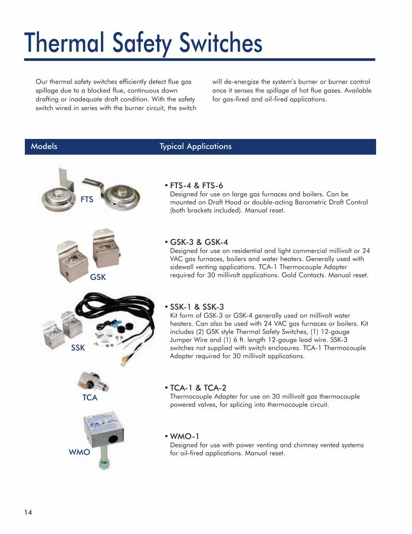
Our thermal safety switches efficiently detect flue gasspillage due to a blocked flue, continuous downdrafting or inadequate draft condition. With the safetyswitch wired in series with the burner circuit, the switch
will de-energize the system’s burner or burner controlonce it senses the spillage of hot flue gases. Availablefor gas-fired and oil-fired applications.
•FTS-4 & FTS-6Designed for use on large gas furnaces and boilers. Can bemounted on Draft Hood or double-acting Barometric Draft Control(both brackets included). Manual reset.
•GSK-3 & GSK-4Designed for use on residential and light commercial millivolt or 24VAC gas furnaces, boilers and water heaters. Generally used withsidewall venting applications. TCA-1 Thermocouple Adapterrequired for 30 millivolt applications. Gold Contacts. Manual reset.
•SSK-1 & SSK-3Kit form of GSK-3 or GSK-4 generally used on millivolt waterheaters. Can also be used with 24 VAC gas furnaces or boilers. Kitincludes (2) GSK style Thermal Safety Switches, (1) 12-gaugeJumper Wire and (1) 6 ft. length 12-gauge lead wire. SSK-3switches not supplied with switch enclosures. TCA-1 ThermocoupleAdapter required for 30 millivolt applications.
•TCA-1 & TCA-2Thermocouple Adapter for use on 30 millivolt gas thermocouplepowered valves, for splicing into thermocouple circuit.
•WMO-1Designed for use with power venting and chimney vented systemsfor oil-fired applications. Manual reset.
FTS
GSK
SSK
TCA
WMO

15
Thermal Safety Switches
NOTE: M = Manual Reset, SPDT = Single Pole Double Throw
On Barometric Draft Controls and draft hoods todetect flue gas spillage and deactivate oil andgas burners.
The Thermal Safety Switch detects the increasedheat generated by the flue gas spillage anddeactivates the furnace or boiler. It will not allowthe burner to restart until the switch has beenmanually reset.
When to use a Thermal Safety SwitchHow Thermal Safety Switches Work
Model Field PartNo.
ContactMaterial
Load-Rating Normally Closed Switch SwitchType
Application
FTS-4 01170004 Silver 126
120 AC240 AC
140°F M SPDTDraft Control or Draft Hood mountingManual reset. Quicker response timethan FTS-6.
FTS-6 01170006 Silver 126
120 AC240 AC
180°F M SPDTDraft Control or Draft Hood mountingManual reset. For use on 24/120/240Volt equipment over 400,000 BTU/hr.
GSK-3 46086400 Gold -24 VA
Millivolt24 AC
180°F M SPDTStandard Gold Contact Manual ResetSwitch. For gas-fired millivolt or 24VAC application.
GSK-4 46086402 Gold -24 VA
Millivolt24 AC
200°F M SPDTManual Reset Switch, same as GSK-3.Where slower response time isa requirement.
SSK-1 46111501 Gold -24 VA
Millivolt24 AC
180°F M SPDTKit includes (2) GSK-3 switches (1)6 ft. length of 12 GA wire and SwitchJumper Wire.
SSK-3 46111503 Gold -24 VA
Millivolt24 AC
200°F M SPDT Kit same as SSK-2 Kit, except switchesnot enclosed in electrical box.
TCA-1 46082700 - - - - - -Required adapter for operation of GoldContact Thermal Safety Switches with 30millivolt systems.
TCA-2 46429900 - - - - - - Same as TCA-1, except with left handedthreads for Flame Guard water heaters.
WMO-1 46086900 Silver 10 120 AC 200°F M SPDTManual reset. Designed for use withpower venting and chimney ventedsystems for oil-fired applications.
AMP Volts Opens Closes
16
Eliminator®Foundation Vent Fan
CRAWL SPACE
THE ELIMINATOR®
FOUNDATION VENT
Eliminate Moisture In Crawl SpacesReduce Fungus, Dry Rot and Termite Potential
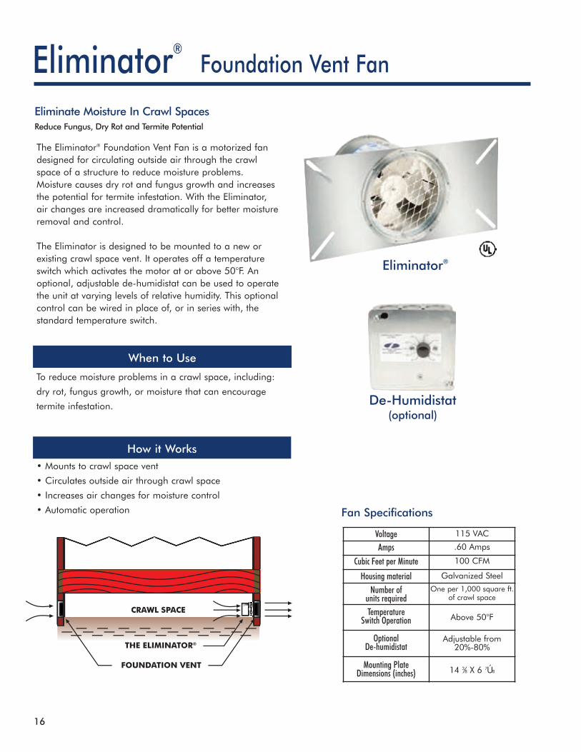
The Eliminator® Foundation Vent Fan is a motorized fandesigned for circulating outside air through the crawlspace of a structure to reduce moisture problems.Moisture causes dry rot and fungus growth and increasesthe potential for termite infestation. With the Eliminator,air changes are increased dramatically for better moistureremoval and control.
The Eliminator is designed to be mounted to a new orexisting crawl space vent. It operates off a temperatureswitch which activates the motor at or above 50°F. Anoptional, adjustable de-humidistat can be used to operatethe unit at varying levels of relative humidity. This optionalcontrol can be wired in place of, or in series with, thestandard temperature switch.
Fan Specifications
Eliminator®
De-Humidistat(optional)
To reduce moisture problems in a crawl space, including:
dry rot, fungus growth, or moisture that can encourage
termite infestation.
How it Works
When to Use
• Mounts to crawl space vent
• Circulates outside air through crawl space
• Increases air changes for moisture control
• Automatic operation
Voltage 115 VAC
Amps .60 Amps
Cubic Feet per Minute 100 CFM
Housing material Galvanized Steel
Number ofunits required
One per 1,000 square ft.of crawl space
TemperatureSwitch Operation Above 50°F
OptionalDe-humidistat
Adjustable from20%-80%
Mounting PlateDimensions (inches) 14 3⁄8 X 6 7Ú8

17
Power VenterI. VISUALLY INSPECT THE GENERAL SYSTEM OPERATION:
1. The thermostat (wall thermostat, or aquastat) calls for heat, starting venter motor.
2. After the venter motor has come up to speed, the pressure switch closes. This closes the circuit to the burner andallows the burner to operate. This occurs in approximately 1 to 2 seconds.
3. After the heating requirement is satisfied, the thermostat circuit opens and deactivates the burner and powerventer circuit.
4. Oil venting systems require a post purge device. During the post purge cycle, the venter operates for a period afterthe burner has shut off. This is to purge the remaining flue gases and to cool the combustion chamber. Typical postpurge times are 3 to 5 minutes. Longer purge times may be required depending on system installation.
II. INSPECTION AND MAINTENANCE ITEMS:
1. Motor: Inspect the motor once a year, it should rotate freely. To prolong the life of the motor, lubricate with six drops ofSWG Super Lube, Part #46226200, annually. Use of any other type of lubricant may cause premature motor failure.
2. Wheel: Inspect the venter wheel annually to clear any soot, ash, or coating which inhibits either rotation or air flow.Remove all foreign materials before operating.
3. Vent System: Inspect all vent connections annually for looseness, for evidence of corrosion, and for flue gas leakage.Replace, seal or tighten pipe connections if necessary. Check the venter choke plate to ensure it is secured in place.Check the barometric draft control to ensure the gate swings freely.
4. System Safety Devices: With the heating system operating, disconnect the pressure sensing tube from the pressureswitch on the CK Kit. This should stop the burner operation. Re-connecting the tube should relight the burner.
III. SYSTEM SETUP AND TESTING:
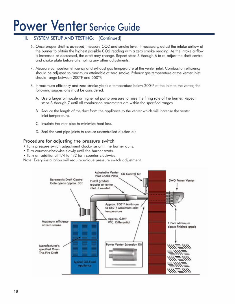
Figure 1 shows a typical oil-fired appliance and the expected ranges of several readings taken at various locations in thesystem. Note: If a vent pipe reducer is required, use a smooth walled gradual reducer. Place it at the venter inlet asshown in Figure 1.
1. Set the choke plate in the power venter, or extension kit, to its full open position. Set the draft control adjustmentweight to its midpoint position.
2. Adjust the thermostat so that the unit will run continuously. Allow the unit to operate for 5 to 10 minutes to ensurestack temperature stabilization.
3. Find out the manufacturer’s recommended over-fire orbreeching draft. Close the choke plate on the SWG until thedraft above the draft control reads approximately 0.04” w.c.greater than the recommended breeching draft. Example: Ifthe appliance manufacturer recommends a 0.02” breechdraft, adjust the choke plate to get an approximate 0.06”draft above the draft control.
4. Adjust the barometric draft control to obtain themanufacturer’s recommended draft over-fire or at the breech.The draft control gate should be open approximately half its full swing during normal operation. This allows the gateto swing open or closed depending on changes in atmospheric pressure or operating conditions.
5. If the proper draft cannot be obtained at the breech or if the gate does not open as described, then adjust the chokeplate in the SWG to reduce or increase the airflow. Re-adjust the draft control to obtain the required draft, sincemoving the choke plate will change the system draft.
Service Guide
• Oil motor and fan shaft withSWG Super Lube annually
• Works in conditions of -40° to300° (F)
• Synthetic lubricant whichmaintains specified viscosity
• Use of any other lubricant maycause premature failure
SWG Super Lube
18
Power VenterIII. SYSTEM SETUP AND TESTING: (Continued)
6. Once proper draft is achieved, measure CO2 and smoke level. If necessary, adjust the intake airflow atthe burner to obtain the highest possible CO2 reading with a zero smoke reading. As the intake airflowis increased or decreased, the draft may change. Repeat steps 3 through 6 to re-adjust the draft controland choke plate before attempting any other adjustments.
7. Measure combustion efficiency and exhaust gas temperature at the venter inlet. Combustion efficiencyshould be adjusted to maximum attainable at zero smoke. Exhaust gas temperature at the venter inletshould range between 200ºF and 550ºF.
8. If maximum efficiency and zero smoke yields a temperature below 200ºF at the inlet to the venter, thefollowing suggestions must be considered.
A. Use a larger oil nozzle or higher oil pump pressure to raise the firing rate of the burner. Repeatsteps 3 through 7 until all combustion parameters are within the specified ranges.
B. Reduce the length of the duct from the appliance to the venter which will increase the venterinlet temperature.
C. Insulate the vent pipe to minimize heat loss.
D. Seal the vent pipe joints to reduce uncontrolled dilution air.
Service Guide
Procedure for adjusting the pressure switch• Turn pressure switch adjustment clockwise until the burner quits.• Turn counter-clockwise slowly until the burner starts.• Turn an additional 1/4 to 1/2 turn counter-clockwise.Note: Every installation will require unique pressure switch adjustment.

©2007 Field Controls form# 4155 Printed in U.S.A.(CP07)
Field Controls, LLC | www.fieldcontrols.com | 2630 Airport Road | Kinston, NC 28504 | TEL: 252.522.3031 | FAX: 252.522.0214
www.fieldcontrols.com