7070677 application of sectionalizers on distribution system
TRANSCRIPT
Conference Papers
Application of Sectionalizerson Distribution Systems
David M. Farmer, P.E.Kent H. Hoffman, P.E.
A2
1-4244-1002-9/07/$25.00 ©2007 IEEEPaper No.
07 A2
A2-1
Abstract -- Sectionalizers, properly applied, can be an integral
part of the distribution protection scheme. A properly designed
scheme is an essential component of a reliable power delivery
system. Where coordination is difficult or impossible with
traditional fault interrupting devices, sectionalizers can be an
effective solution. Many of the issues related to improper
operation are a result of how and where the device is applied.
Successful application of sectionalizers requires an
understanding of their operation, their proper role in the overall
scheme, and the training of operations personnel in
troubleshooting circuits where they are applied.
This paper addresses the essential attributes of integrating
sectionalizers into the protection scheme, as well as potential
pitfalls and failure modes and how they can be minimized.
Coordination with other protective devices and device reach will
be discussed along with their potential impact on reliability.
Index Terms— Power Distribution Protection, Power
Distribution Reliability, Power Distribution Control, Power
Distribution Faults
I. INTRODUCTION
An automatic line sectionalizer (Sectionalizer) is an
automatic switch that does not interrupt fault currents, does
not have time-current characteristics, and is dependent on the
operating of a source-side device for proper function. Because
it does not interrupt fault currents and is not capable of
operating independently, it should not be thought of as a
protective device in the classical sense, but should be thought
of as an automated switch. These characteristics give
sectionalizers distinct advantages over protective devices.
There is: 1) no need to be concerned about interrupting rating,
2) no need to time-current coordinate with load-side fuses or
source-side reclosers, and 3) they are a solution for temporary
faults in areas where the fault currents are too high for fuse
saving. But most good things come with trade-offs.
Automatic line sectionalizers have the disadvantage of relying
on assumptions rather than direct information for determining
proper operation. This reliance on assumptions, which may be
faulty, is more likely to result in unexpected operation or
failure to operate than fuses, reclosers or circuit breakers.
There are two general types of current sensing
Manuscript received January 12, 2007.
D. M. Farmer, PE is with Synergetic Design, Inc.; Raleigh, NC 27607
USA; phone: 919-787-7000, ext. 223; fax: 919-787-7055; email:
K. H. Hoffman, PE was with Progress Energy, Raleigh, NC 27602 USA.
He is now with the Synergetic Design, Inc.; Raleigh, NC 27607 USA; phone:
919-787-7000; fax: 919-787-7055; email; [email protected].
sectionalizers: hydraulic sectionalizers that look like small
single phase reclosers and electronic sectionalizers that look
like a solid barrel or blade cutout with a “donut” current
transformer around the middle of the barrel. In past decades
the dominant sectionalizer was the “hydraulic” sectionalizer.
Its application was limited to light loading behind a single
recloser with a 1-3 operating sequence. But the development
of electronic sectionalizers in recent years has resulted in
sectionalizers that can operate properly when carrying large
loads; behind reclosers with a 2-2 operating sequence; and
when placed to the source side of reclosers.
II. HOW SECTIONALIZERS WORK
Sectionalizers are automatic switches that are controlled by
a built-in logic system. The logic system uses operations of a
source side reclosing device to determine if a permanent fault
is occurring in the sectionalizer protection zone and, if so, to
automatically open the sectionalizer during one of the source-
side recloser temporary open periods. After the sectionalizer
opens, the source-side recloser closes, restoring service to
unaffected sections of the system. If the fault is temporary
and is cleared before the sectionalizer count reaches the
predetermined number, the sectionalizer remains closed and
resets to its original state after a predetermined time period.
Sectionalizers may be single-phase or three-phase switching
and the logic system may key on current or voltage. The focus
of this discussion will be single-phase current controlled
sectionalizers, which are the most commonly applied
sectionalizers. The logic system of current sensing
sectionalizers must make three decisions, and if the outcome
of those decisions match the logic scheme, then it will
automatically open the sectionalizer while the circuit is de-
energized by a source-side reclosing device.
The sectionalizer must determine that a fault exists in the
circuit beyond it (the load-side circuit). It does this by
recognizing a current flowing through the sectionalizer that
exceeds a predetermined current “threshold”, typically 160%
of the sectionalizer rating. This current is called the actuating
current or the arm-to-count current.
The sectionalizer must determine that the fault is not
temporary in nature. It does this by “counting” the number of
times that a source side reclosing device operates, determined
by the number of times in a set time period that an actuating
current has occurred followed by a low current indication. A
low current indication is a current below the “minimum
threshold” (indicating a de-energized circuit), typically 64% of
the sectionalizer rating for hydraulic sectionalizers and 300
mA for electronic sectionalizers. For hydraulic sectionalizers,
Application of Sectionalizers on Distribution Systems
David M. Farmer, PE, Member, IEEE and Kent H. Hoffman, PE
A2-2
currents below the minimum threshold may include load
current, while for electronic sectionalizers, currents below the
minimum threshold should be below minimum load current
levels. It is typical for sectionalizers to assume that a fault is
permanent if there are 2 or 3 counts in a set time frame (about
two minutes for an electronic sectionalizer).
The sectionalizer should determine that the fault is not
being cleared by a load-side protective device, such as a fuse
or recloser. Hydraulic sectionalizers typically can determine
that the actuating current has been cleared, but are not able to
determine if the current was cleared by a source side recloser
or a load side fuse. This must be taken into account when
applying a hydraulic sectionalizer, usually by reducing the fast
operations of the source-side recloser by one to account for the
fuse blowing. Electronic sectionalizers will “actuate” or “arm-
to-count” when they see current in excess of their threshold,
but when the actuating current goes away, they will not count
if they sense load current (typically defined as 300 mA or
more), assuming that a load side fuse or recloser cleared the
fault. If an electronic sectionalizer does not sense 300 mA
following an actuating current event, it will assume that a
source-side reclosing device cleared the fault, so the
sectionalizer will count [1]-[3].
These determinations are made without direct
communications with the associated source and load-side
protective devices, thus are assumptions deduced from current
measurements made at the sectionalizer location. For this
reason, sectionalizers are more likely than protective devices
to fail to operate as expected. This is caused by unusual
circumstances which cause the operating assumptions to be
inaccurate. For example, a sectionalizer will never open
automatically when the source-side recloser is set for non-
reclosing or any situation where the source side reclosing
device does not go through the operating sequence.
III. SECTIONALIZER APPLICATION EXAMPLES
Below are examples of typical sectionalizer operations. All
of these examples include a sectionalizer with a source-side
reclosing device and a load-side fuse or recloser.
Hydraulic Sectionalizer (3 count) sequence for a fault
beyond a load-side fuse when the sectionalizer is behind a 2-2
recloser
• Fault 1 – Current flows through the recloser, sectionalizer,
and fuse. The sectionalizer arms. The recloser opens on
the fast curve, protecting the fuse. The sectionalizer
counts “one”
• Fault 2 – The recloser closes and the sectionalizer arms.
The recloser opens on the fast curve, protecting the fuse.
The sectionalizer counts “two”
• Fault 3 – The recloser closes and the sectionalizer arms.
The recloser opens on the slow curve, the fuse blows.
The sectionalizer counts “three” and opens because the
current falls below 64% of the sectionalizer rating. There
are now two devices open.
Hydraulic Sectionalizer (3 count) sequence for a fault
beyond a load-side fuse when the sectionalizer is behind a 1-3
recloser
• Fault 1 – Current flows through the recloser,
sectionalizer, and fuse. The sectionalizer arms. The
recloser opens on the fast curve, protecting the fuse.
The sectionalizer counts “one”
• Fault 2 – The recloser closes and the sectionalizer arms.
The recloser opens on the slow curve, the fuse blows.
The sectionalizer counts “two” because the current falls
below 64% of the sectionalizer rating but remains
closed because it has not reached full count. There is
now only one device open, the fuse closest to the fault.
Electronic Sectionalizer (3 count) sequence for a fault
beyond a load-side fuse when the sectionalizer is behind a 2-2
recloser
• Fault 1 – Current flows through the recloser,
sectionalizer, and fuse. The sectionalizer arms. The
recloser opens on the fast curve, protecting the fuse.
The sectionalizer counts “one”
• Fault 2 – The recloser closes and the sectionalizer arms.
The recloser opens on the fast curve, protecting the
fuse. The sectionalizer counts “two”
• Fault 3 – The recloser closes and the sectionalizer arms.
The recloser opens on the slow curve, the fuse blows.
The sectionalizer does not count and remains closed
because more than 300 of load current exists. There is
now only one device open, the fuse closest to the fault.
Both hydraulic and electronic sectionalizers function by
counting combinations of over currents and over current
interruptions. This generally prohibits application beyond
more than one hydraulic recloser. This can be illustrated by
the example of an electronic sectionalizer (3 count) beyond
two 2-2 reclosers
• Fault 1 – Current flows through the reclosers,
sectionalizer, and fuse. The sectionalizer arms. If the
fault current is a relatively lower value, the smaller
load-side recloser will operate on a fast curve,
protecting the fuse. The sectionalizer counts “one”
• Fault 2 – The recloser closes and the sectionalizer arms.
The smaller load-side recloser opens on the fast curve,
protecting the fuse. The sectionalizer counts “two”
• Fault 3 – The recloser closes and the sectionalizer arms.
The larger source-side recloser opens on a fast curve,
protecting the fuse. The sectionalizer counts three and
opens. The fault is beyond the fuse which has not
blown, misleading service restoration personnel into
searching for the fault in the sectionalizer zone of
protection.
In most fault conditions it is probable that the two reclosers
in the above example would operate simultaneously on their
fast curves, resulting in correct operation of the sectionalizer
and fuse. But the risk and consequences of improper
operation leads us to recommend against applying
sectionalizers beyond two hydraulic reclosers. One exception
A2-3
to the rule might be sectionalizer placement beyond two
hydraulic reclosers of the same size but coordinated by
different slow curve types, such as a 2A-2B recloser
coordinated beyond a 2A-2C recloser. In this case the “A”
curves should operate simultaneously, resulting in correct
operation of the sectionalizer and fuse.
A similar consideration should be the “fast operations”,
such as an instantaneous relay, on feeder circuit breakers or
source-side electronic reclosers. If this “relay” is faster than
the slow curve of the hydraulic recloser that is being
coordinated with the sectionalizer and if it “reaches” into the
zone of the sectionalizer, then it may result in an additional
operation of the sectionalizer. For a three count hydraulic
sectionalizer beyond a 1-3 recloser this might result in a
simultaneous sectionalizer and fuse opening. A three count
electronic sectionalizer will coordinate properly with fuses if
the source-side 2-2 hydraulic recloser is replaced with a 1-3
recloser. Potential problems in this area can be avoided by
assuring that feeder circuit breaker or source-side electronic
reclosers have fast operations that do not “reach” into the
sectionalizer zones or have fast operations that are “sequence
coordinated” with the hydraulic recloser fast operations.
Sequence coordination is a logic function in most electronic
relays and reclosers that cause the relay or recloser to bypass
fast operations when they detect fault currents greater than the
fast curve “pick-up” that are interrupted before reaching the
fast curve trip time. Sequence coordination assumes that
faults meeting these conditions are interrupted by a load-side
recloser. The fast operation is then bypassed, allowing the
load-side recloser to operate on slow curves without causing
an unnecessary interruption of customers on the breaker or
recloser.
Hydraulic sectionalizers are limited in loading due to
potential mis-operations from inrush currents. The design of
electronic sectionalizers eliminates this problem through
inrush restraint and blocking count if load current (greater than
300 ma) is present following an over current event. The
ability of electronic sectionalizers to carry high load currents
(up to 200 amps) and not be affected by inrush makes it
possible to use them to the source-side of hydraulic reclosers.
The key consideration in applying sectionalizers to the source-
side of reclosers is to assure that there is a minimum of 300
milliamps of load current on each phase of the zone between
the sectionalizer and the reclosers, even during the lightest
loaded off-peak condition. A secondary consideration is to
assure that during peak load conditions, opening of a
sectionalizer will not create an imbalance capable of tripping a
ground protection of the source-side breaker or recloser.
Where these considerations are met, a typical fault would
produce the following operation.
Electronic Sectionalizer (2 count) sequence for a fault
beyond a load-side 2-2 recloser when the sectionalizer is
behind a 1-3 circuit breaker or recloser
• Fault 1 – Current flows through the source-side
breaker, sectionalizer, and load-side recloser. The
sectionalizer arms. The recloser opens on the fast
curve, clearing the fault. When the recloser opens, the
over current disappears but the load current in the
sectionalizer zone does not drop below 300 milliamps.
Therefore the sectionalizer does not count.
• Fault 2 – The load-side recloser closes and the
sectionalizer arms. The recloser opens on the fast
curve, clearing the fault. The sectionalizer continues to
see load current and does not count.
• Fault 3 – The load-side recloser closes and the
sectionalizer arms. The recloser is now on the slow
curve, causing the source-side breaker to clear the fault
on its fast curve (this would not occur with properly
applied sequence coordination). The sectionalizer sees
current drop below 300 milliamps and counts “one”.
• Fault 4 – The source-side device closes and the
sectionalizer arms. The recloser opens on the slow
curve, clearing the fault. The sectionalizer continues to
see load current and does not count.
• Fault 5 – The load-side recloser closes and the
sectionalizer arms. The recloser opens on the slow
curve, locks out. The sectionalizer continues to see
load current and does not count. The sectionalizer will
reset to “zero” count after about 2 minutes.
Electronic Sectionalizer (2 count) sequence for a fault
between the sectionalizer and a load-side 2-2 recloser when
the sectionalizer is behind a 1-3 circuit breaker or recloser
• Fault 1 – Current flows through the source-side breaker
and sectionalizer. The sectionalizer arms. The source-
side breaker opens on the fast curve, clearing the fault.
When the breaker opens, the sectionalizer sees current
drop below 300 milliamps and counts “one”.
• Fault 2 – The source-side breaker closes and the
sectionalizer arms. The source-side breaker opens on
the slow curve, clearing the fault. The sectionalizer
sees current drop below 300 milliamps and opens.
Note: Had Fault 2 been on a fused tap beyond the
sectionalizer, the fuse would blow, the sectionalizer would
continue to see load current and would not count.
A2-4
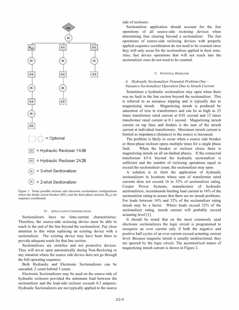
Figure 1. Some possible recloser and electronic sectionalizer configurations
where the feeder circuit breaker (SEL) and the three-phase recloser (R3ph) are
sequence coordinated.
IV. APPLICATION CONSIDERATIONS
Sectionalizers have no time-current characteristics.
Therefore, the source-side reclosing device must be able to
reach to the end of the line beyond the sectionalizer. Pay close
attention to this when replacing an existing device with a
sectionalizer. The existing device may have been there to
provide adequate reach for that line section.
Sectionalizers are switches and not protective devices.
They will never open automatically during Non-Reclosing or
any situation where the source side device does not go through
the full operating sequence.
Both Hydraulic and Electronic Sectionalizers can be
cascaded, 2 count behind 3 count.
Electronic Sectionalizers may be used on the source-side of
hydraulic reclosers provided the minimum load between the
sectionalizer and the load-side recloser exceeds 0.3 amperes.
Hydraulic Sectionalizers are not typically applied to the source
side of reclosers.
Sectionalizer application should account for the fast
operations of all source-side reclosing devices when
determining fuse clearing beyond a sectionalizer. The fast
operations of source-side reclosing devices with properly
applied sequence coordination do not need to be counted since
they will only occur for the sectionalizer applied in their zone.
Also, fast device operations that will not reach into the
sectionalizer zone do not need to be counted.
V. POTENTIAL PROBLEMS
A. Hydraulic Sectionalizer Potential Problem One –
Nuisance Sectionalizer Operation Due to Inrush Current
Sometimes a hydraulic sectionalizer may open when there
was no fault in the line section beyond the sectionalizer. This
is referred to as nuisance tripping and is typically due to
magnetizing inrush. Magnetizing inrush is produced by
saturation of iron in transformers and can be as high as 25
times transformer rated current at 0.01 second and 12 times
transformer rated current at 0.1 second. Magnetizing inrush
current on tap lines and feeders is the sum of the inrush
current at individual transformers. Maximum inrush current is
limited as impedance (distance) to the source is increased.
The problem is likely to occur when a source side breaker
or three-phase recloser opens multiple times for a single phase
fault. When the breaker or recloser closes there is
magnetizing inrush on all un-faulted phases. If the connected
transformer kVA beyond the hydraulic sectionalizer is
sufficient and the number of reclosing operations equal or
exceed the sectionalizer count, the sectionalizer may open.
A solution is to limit the application of hydraulic
sectionalizers to locations where sum of transformer rated
currents does not exceed 16 to 32% of sectionalizer rating.
Cooper Power Systems, manufacturer of hydraulic
sectionalizers, recommends limiting load current to 16% of the
sectionalizer rating to assure that there are no inrush problems.
For loads between 16% and 32% of the sectionalizer rating
inrush may be a factor. Where loads exceed 32% of the
sectionalizer rating, inrush current will probably exceed
actuating level [1].
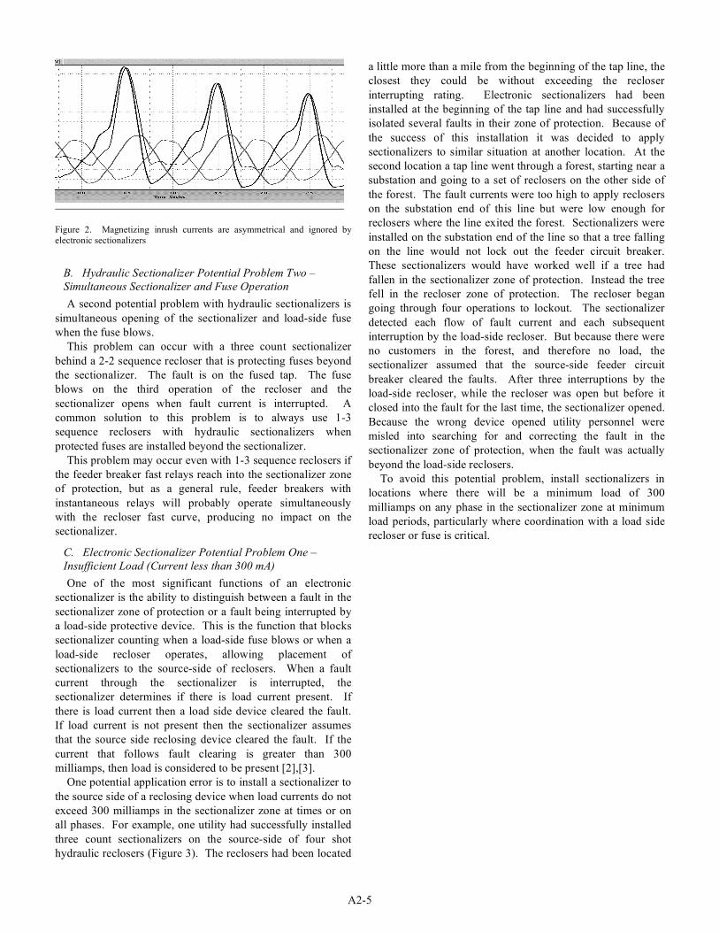
It should be noted that on the most commonly used
electronic sectionalizers the logic circuit is programmed to
recognize an over current only if both the negative and
positive half cycles of an over current exceed actuating current
level. Because magnetic inrush is usually unidirectional, they
are ignored by the logic circuit. The asymmetrical nature of
magnetizing inrush current is shown in Figure 2.
A2-5
Figure 2. Magnetizing inrush currents are asymmetrical and ignored by
electronic sectionalizers
B. Hydraulic Sectionalizer Potential Problem Two –
Simultaneous Sectionalizer and Fuse Operation
A second potential problem with hydraulic sectionalizers is
simultaneous opening of the sectionalizer and load-side fuse
when the fuse blows.
This problem can occur with a three count sectionalizer
behind a 2-2 sequence recloser that is protecting fuses beyond
the sectionalizer. The fault is on the fused tap. The fuse
blows on the third operation of the recloser and the
sectionalizer opens when fault current is interrupted. A
common solution to this problem is to always use 1-3
sequence reclosers with hydraulic sectionalizers when
protected fuses are installed beyond the sectionalizer.
This problem may occur even with 1-3 sequence reclosers if
the feeder breaker fast relays reach into the sectionalizer zone
of protection, but as a general rule, feeder breakers with
instantaneous relays will probably operate simultaneously
with the recloser fast curve, producing no impact on the
sectionalizer.
C. Electronic Sectionalizer Potential Problem One –
Insufficient Load (Current less than 300 mA)
One of the most significant functions of an electronic
sectionalizer is the ability to distinguish between a fault in the
sectionalizer zone of protection or a fault being interrupted by
a load-side protective device. This is the function that blocks
sectionalizer counting when a load-side fuse blows or when a
load-side recloser operates, allowing placement of
sectionalizers to the source-side of reclosers. When a fault
current through the sectionalizer is interrupted, the
sectionalizer determines if there is load current present. If
there is load current then a load side device cleared the fault.
If load current is not present then the sectionalizer assumes
that the source side reclosing device cleared the fault. If the
current that follows fault clearing is greater than 300
milliamps, then load is considered to be present [2],[3].
One potential application error is to install a sectionalizer to
the source side of a reclosing device when load currents do not
exceed 300 milliamps in the sectionalizer zone at times or on
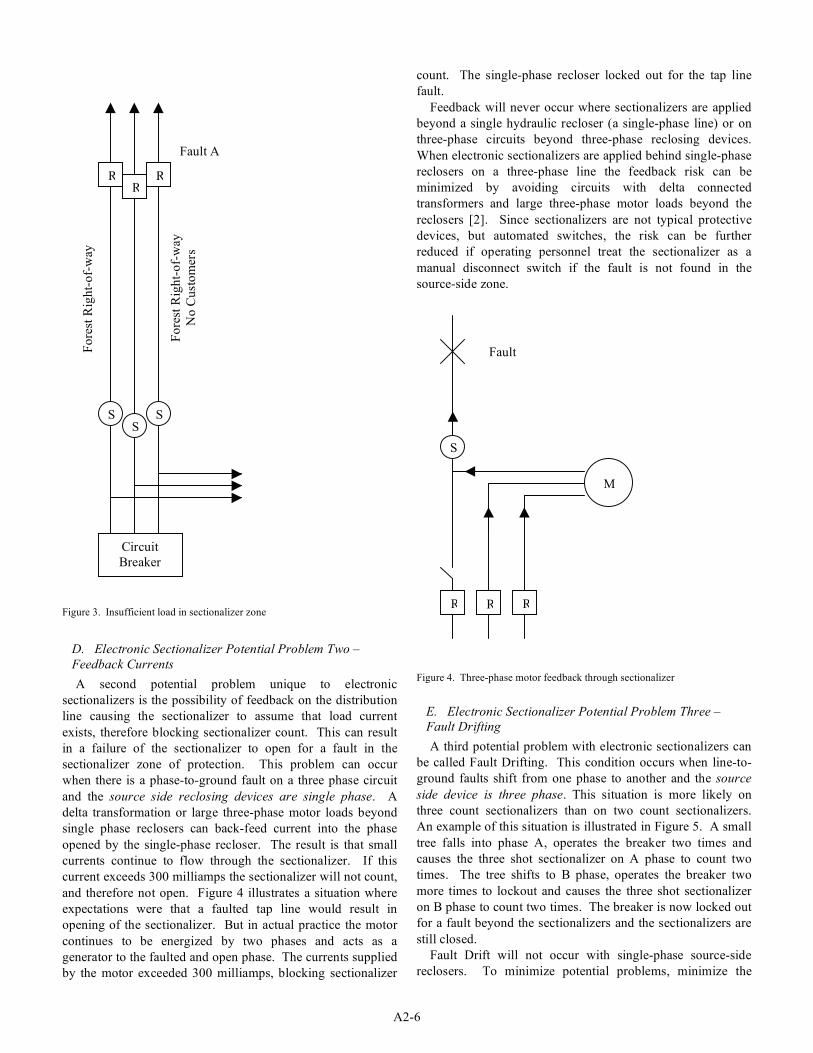
all phases. For example, one utility had successfully installed
three count sectionalizers on the source-side of four shot
hydraulic reclosers (Figure 3). The reclosers had been located
a little more than a mile from the beginning of the tap line, the
closest they could be without exceeding the recloser
interrupting rating. Electronic sectionalizers had been
installed at the beginning of the tap line and had successfully
isolated several faults in their zone of protection. Because of
the success of this installation it was decided to apply
sectionalizers to similar situation at another location. At the
second location a tap line went through a forest, starting near a
substation and going to a set of reclosers on the other side of
the forest. The fault currents were too high to apply reclosers
on the substation end of this line but were low enough for
reclosers where the line exited the forest. Sectionalizers were
installed on the substation end of the line so that a tree falling
on the line would not lock out the feeder circuit breaker.
These sectionalizers would have worked well if a tree had
fallen in the sectionalizer zone of protection. Instead the tree
fell in the recloser zone of protection. The recloser began
going through four operations to lockout. The sectionalizer
detected each flow of fault current and each subsequent
interruption by the load-side recloser. But because there were
no customers in the forest, and therefore no load, the
sectionalizer assumed that the source-side feeder circuit
breaker cleared the faults. After three interruptions by the
load-side recloser, while the recloser was open but before it
closed into the fault for the last time, the sectionalizer opened.
Because the wrong device opened utility personnel were
misled into searching for and correcting the fault in the
sectionalizer zone of protection, when the fault was actually
beyond the load-side reclosers.
To avoid this potential problem, install sectionalizers in
locations where there will be a minimum load of 300
milliamps on any phase in the sectionalizer zone at minimum
load periods, particularly where coordination with a load side
recloser or fuse is critical.
A2-6
Figure 3. Insufficient load in sectionalizer zone
D. Electronic Sectionalizer Potential Problem Two –
Feedback Currents
A second potential problem unique to electronic
sectionalizers is the possibility of feedback on the distribution
line causing the sectionalizer to assume that load current
exists, therefore blocking sectionalizer count. This can result
in a failure of the sectionalizer to open for a fault in the
sectionalizer zone of protection. This problem can occur
when there is a phase-to-ground fault on a three phase circuit
and the source side reclosing devices are single phase. A
delta transformation or large three-phase motor loads beyond
single phase reclosers can back-feed current into the phase
opened by the single-phase recloser. The result is that small
currents continue to flow through the sectionalizer. If this
current exceeds 300 milliamps the sectionalizer will not count,
and therefore not open. Figure 4 illustrates a situation where
expectations were that a faulted tap line would result in
opening of the sectionalizer. But in actual practice the motor
continues to be energized by two phases and acts as a
generator to the faulted and open phase. The currents supplied
by the motor exceeded 300 milliamps, blocking sectionalizer
count. The single-phase recloser locked out for the tap line
fault.
Feedback will never occur where sectionalizers are applied
beyond a single hydraulic recloser (a single-phase line) or on
three-phase circuits beyond three-phase reclosing devices.
When electronic sectionalizers are applied behind single-phase
reclosers on a three-phase line the feedback risk can be
minimized by avoiding circuits with delta connected
transformers and large three-phase motor loads beyond the
reclosers [2]. Since sectionalizers are not typical protective
devices, but automated switches, the risk can be further
reduced if operating personnel treat the sectionalizer as a
manual disconnect switch if the fault is not found in the
source-side zone.
Figure 4. Three-phase motor feedback through sectionalizer
E. Electronic Sectionalizer Potential Problem Three –
Fault Drifting
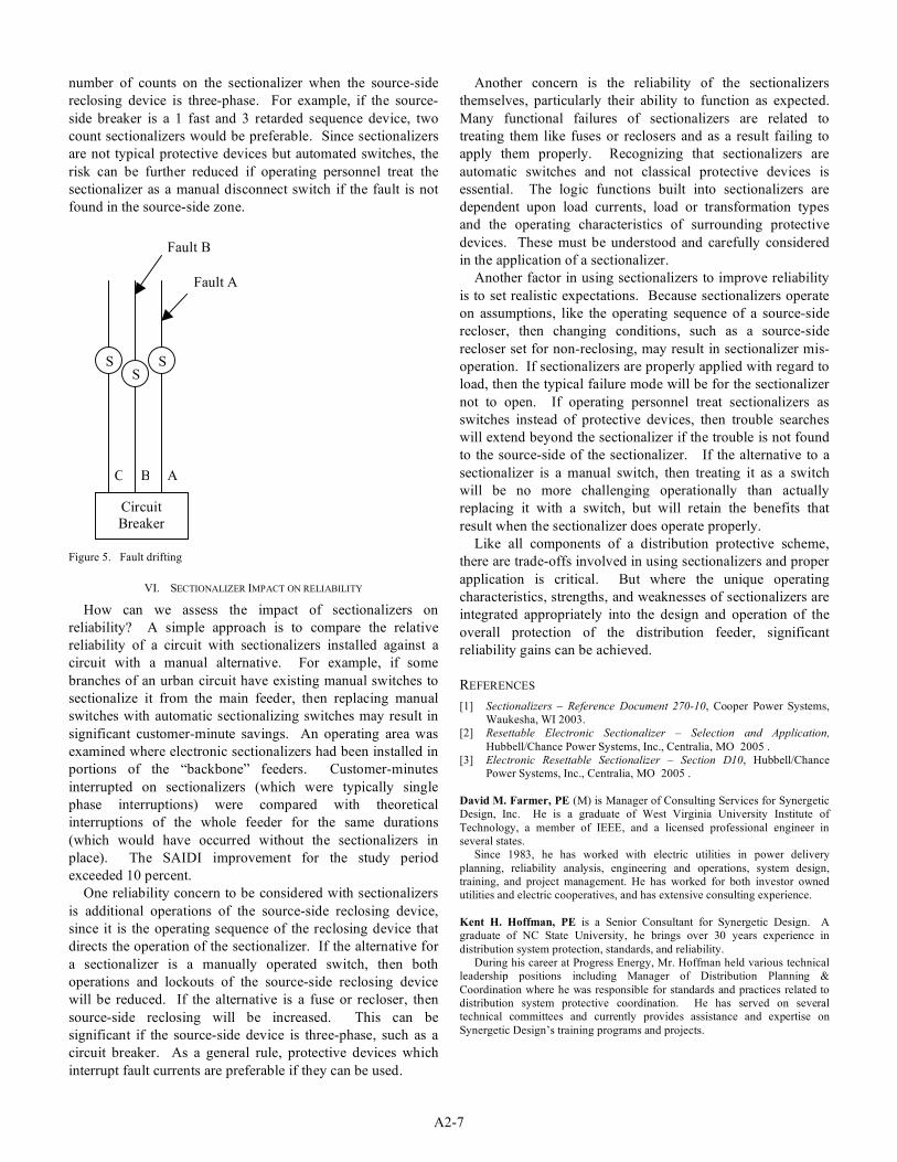
A third potential problem with electronic sectionalizers can
be called Fault Drifting. This condition occurs when line-to-
ground faults shift from one phase to another and the source
side device is three phase. This situation is more likely on
three count sectionalizers than on two count sectionalizers.
An example of this situation is illustrated in Figure 5. A small
tree falls into phase A, operates the breaker two times and
causes the three shot sectionalizer on A phase to count two
times. The tree shifts to B phase, operates the breaker two
more times to lockout and causes the three shot sectionalizer
on B phase to count two times. The breaker is now locked out
for a fault beyond the sectionalizers and the sectionalizers are
still closed.
Fault Drift will not occur with single-phase source-side
reclosers. To minimize potential problems, minimize the
Fo
rest
Rig
ht-
of-
way
Circuit
Breaker
Fault A
SS
S
RRR
Fo
rest
Rig
ht-
of-
way
No
Cu
sto
mer
s
R
S
R R
Fault
M
A2-7
number of counts on the sectionalizer when the source-side
reclosing device is three-phase. For example, if the source-
side breaker is a 1 fast and 3 retarded sequence device, two
count sectionalizers would be preferable. Since sectionalizers
are not typical protective devices but automated switches, the
risk can be further reduced if operating personnel treat the
sectionalizer as a manual disconnect switch if the fault is not
found in the source-side zone.
Figure 5. Fault drifting
VI. SECTIONALIZER IMPACT ON RELIABILITY
How can we assess the impact of sectionalizers on
reliability? A simple approach is to compare the relative
reliability of a circuit with sectionalizers installed against a
circuit with a manual alternative. For example, if some
branches of an urban circuit have existing manual switches to
sectionalize it from the main feeder, then replacing manual
switches with automatic sectionalizing switches may result in
significant customer-minute savings. An operating area was
examined where electronic sectionalizers had been installed in
portions of the “backbone” feeders. Customer-minutes
interrupted on sectionalizers (which were typically single
phase interruptions) were compared with theoretical
interruptions of the whole feeder for the same durations
(which would have occurred without the sectionalizers in
place). The SAIDI improvement for the study period
exceeded 10 percent.
One reliability concern to be considered with sectionalizers
is additional operations of the source-side reclosing device,
since it is the operating sequence of the reclosing device that
directs the operation of the sectionalizer. If the alternative for
a sectionalizer is a manually operated switch, then both
operations and lockouts of the source-side reclosing device
will be reduced. If the alternative is a fuse or recloser, then
source-side reclosing will be increased. This can be
significant if the source-side device is three-phase, such as a
circuit breaker. As a general rule, protective devices which
interrupt fault currents are preferable if they can be used.
Another concern is the reliability of the sectionalizers
themselves, particularly their ability to function as expected.
Many functional failures of sectionalizers are related to
treating them like fuses or reclosers and as a result failing to
apply them properly. Recognizing that sectionalizers are
automatic switches and not classical protective devices is
essential. The logic functions built into sectionalizers are
dependent upon load currents, load or transformation types
and the operating characteristics of surrounding protective
devices. These must be understood and carefully considered
in the application of a sectionalizer.
Another factor in using sectionalizers to improve reliability
is to set realistic expectations. Because sectionalizers operate
on assumptions, like the operating sequence of a source-side
recloser, then changing conditions, such as a source-side
recloser set for non-reclosing, may result in sectionalizer mis-
operation. If sectionalizers are properly applied with regard to
load, then the typical failure mode will be for the sectionalizer
not to open. If operating personnel treat sectionalizers as
switches instead of protective devices, then trouble searches
will extend beyond the sectionalizer if the trouble is not found
to the source-side of the sectionalizer. If the alternative to a
sectionalizer is a manual switch, then treating it as a switch
will be no more challenging operationally than actually
replacing it with a switch, but will retain the benefits that
result when the sectionalizer does operate properly.
Like all components of a distribution protective scheme,
there are trade-offs involved in using sectionalizers and proper
application is critical. But where the unique operating
characteristics, strengths, and weaknesses of sectionalizers are
integrated appropriately into the design and operation of the
overall protection of the distribution feeder, significant
reliability gains can be achieved.
REFERENCES
[1] Sectionalizers – Reference Document 270-10, Cooper Power Systems,
Waukesha, WI 2003.
[2] Resettable Electronic Sectionalizer – Selection and Application,
Hubbell/Chance Power Systems, Inc., Centralia, MO 2005 .
[3] Electronic Resettable Sectionalizer – Section D10, Hubbell/Chance
Power Systems, Inc., Centralia, MO 2005 .
David M. Farmer, PE (M) is Manager of Consulting Services for Synergetic
Design, Inc. He is a graduate of West Virginia University Institute of
Technology, a member of IEEE, and a licensed professional engineer in
several states.
Since 1983, he has worked with electric utilities in power delivery
planning, reliability analysis, engineering and operations, system design,
training, and project management. He has worked for both investor owned
utilities and electric cooperatives, and has extensive consulting experience.
Kent H. Hoffman, PE is a Senior Consultant for Synergetic Design. A
graduate of NC State University, he brings over 30 years experience in
distribution system protection, standards, and reliability.
During his career at Progress Energy, Mr. Hoffman held various technical
leadership positions including Manager of Distribution Planning &
Coordination where he was responsible for standards and practices related to
distribution system protective coordination. He has served on several
technical committees and currently provides assistance and expertise on
Synergetic Design’s training programs and projects.
Fault A
Circuit
Breaker
Fault B
S S
S
C B A