7.1 organic liquid storage tanks related information royce ... · pdf filethen existing api...
TRANSCRIPT

AP42 Section:
Related Information
7.1 Organic Liquid Storage Tanks
Title: Evaporative Loss from Storage Tanks
Royce J. Laverman Chicago Bridge and Iron Co.
Presented at the 4th Oil Loss Control Conference, London, England
October 1991

EVA,POMTIVE LOSS FROM STORAGE TANKS
BY:
ROYCE J. LAVERMAN
PLAINFIELD, ILLINOIS
CHICAGO BRIDGE & IRON COMPANY RESEARCH CENTER
THE FOURTH OIL Loss CONTROL CONFERENCE
"REAL AND APPARENT LOSSES IN REFINING AND STORAGE"
THE INSTITUTE OF PETROLEUM LONDON, UNITED KINGDOM
OCTOBER 30-3 1, 199 1
CBI TECHNICAL PUBLICATION NUMBER CB T-5562

"'I \I ... A 1 I I I I I I I I I I I I I I I I
TABLE OF CONTENTS
SECTION DESCRIPTION PAGE ABSTRACT ......................................................... v
1.0 INTRODUCTION ..................................................... 1-1
2.0 LOSS SOURCES ..................................................... 2-1
2.1 EFRT Loss Sources ........................................... 2-1 2.1.1 EFRT R i m Seals ....................................... 2-2 2.1.2 EFRT 'Roof F i t t i n g s ................................... 2-3 2.1.3 EFRT Stock Clingage .................................. 2-4
2.2 IFRT Loss Sources ........................................... 2-4 2.2.1 IFRT R i m Seals ....................................... 2-6 2.2.2 IFRT Roof F i t t i n g s ................................... 2-6 2.2.3 IFRT Stock Clingage .................................. 2-7 2.2.4 IFRT Roof Seams ...................................... 2-7 FRT. Loss Sources ............................................ 2-8 2.3.1 FRT Roof F i t t i n g s .................................... 2-8
2.3
3.0 LOSS MECHANISMS ................................................... 3-1
3.1 B o i l i n g ..................................................... 3-2 3.2 Breathing ................................................... 3 - 2 3.3 Clingage .................................................... 3-3 3.4 Convection ................................................... 3-3 3.5 Desorption .................................................. 3-4 3.6 D i f f u s i o n ................................................... 3-4 3.7 Displacement ................................................ 3-4 3.8 Permeation .................................................. 3-5 3.9 Wicking ..................................................... 3-5
LOSS MEASUREMENT METHODS ......................................... 4-1
4.1 F i e l d Tank Tests ............................................ 4-1 4.1.1 Stock Densi ty Change Method .......................... 4-1 4.1.2 Vented Vapor Measurement Method ...................... 4-2 P i l o t Tank Tests ............................................ 4-3 Wind Tunnel Tests ........................................... 4-4 Stock C1 ingage Tests ........................................ 4-5
EFRT AND IFRT LOSS CALCULATION METHODS ........................... 5 - 1
EFRT and I F R T Loss Equations ................................ 5-2 5.2 R i m Seal Loss Factor ........................................ 5-4
Stock Clingage Factor ....................................... 5-6
4.0
4.2 4.3 4.4
5.0
5.1
5.3 Roof F i t t i n g Loss Factor .................................... 5-4 5.4 Roof Seam Loss Factor ....................................... 5-5 5.5 Product Factor .............................................. 5-5 5.6
i
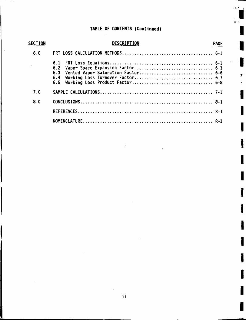
TABLE OF CONTENTS (Continued) F'
i i PAGE - SECTION DESCRIPTION
6.0 FRT LOSS CALCULATION METHODS.. . . . . . . . . . . . . . . . . . . . . . . . . . . . . . . . . . . . 6-1
i
1 1 1
6.1 FRT L o s s Equations .......................................... 6-1 6 .2 Vapor Space Expansion Factor ................................ 6-3 6.3 Vented Vapor Saturation Factor ....... ..... .. . ...... ......... 6-6 6 .4 Working Loss Turnover Factor ................................ 6-7 6.5 Working Loss Product Factor ................................. 6-8
3
-
7.0 SAMPLE CALCULATIONS .............................................. 7-1
8 .0 CONCLUSIONS ...................................................... 8-1
REFERENCES ....................................................... R - 1
NOMENCLATURE.. . . . . . . . . . . . . . . . . . . . . . . . . . . . . . . . . . . . . . . . . . . . . . . . . . . . R-3
ii

m ..
I I I I I I
rn m
m m I I I I- B I I
1 . 2 . 3 . 4 . 5 . 6 . 7 . 8 . 9 . 10 . 11 . 12 . 13 . 14 . 15 . 16 . 17 . 18 . 19 . 20 . 21 . 22 . 23 . 24 . 25 . 26 . 27 . 28 . 29 . 30 . 31 . 32 . 33 . 34 .
LIST OF FIGURES
DESCRIPTION . PAGE
Typical External Floating-Roof Tank (EFRT) With a Pontoon
Typical External Floating-Roof Tank (EFRT) With a Double-Deck F loa t ing Roof .................................................... F - 1
L i a u i d-Mounted Resi 1 i ent -F i 11 ed ( L i guid- F i 11 ed) Primary Seal
F loa t ing Roof .................................................... F - 1
Mechanical-Shoe Primary Seal With a Rim-Mounted Secondary Seal ... F-2
With a Rim-Mounted Secondary Seal ....... Liquid-Mounted Resi 1 i e n t - F i l l e d (Foam-F With a Rim-Mounted Secondary Seal ...... Vapor-Mounted R e s i l i e n t - F i l l e d (Foam-Fi With a Rim-Mounted Secondary Seal ...... Access Hatch ........................... R i m Vent ............................... Gauge-Hatch/Sample Well ................. Vacuum Breaker .......................... Gauge-Float Well ........................
................. l l e d ) Primary Sea
led) Primary Seal ................. ................. ................. .................
....... F-2
....... F-2
....... F-2 ....... F-3 ....... F-3 ......................... F-3 ......................... F-3 _ _ ......................... F-3 .......................... F-4 Roof Leg ............................... Overflow Roof Drain .............................................. F-4 Unslot ted Guide-Pole Well ........................................ F-4 S l o t t e d Guide-Pole/Sample Well ................................... F-4 Typical I n t e r n a l Floating-Roof Tank ( IFRT) With a Welded F loa t ing Roof .................................................... F-5 Typical Fixed-Roof Tank (FRT) .................................... F-5 D a i l y Ambient Heating-Related Breathing Loss Mechanism on a FRT .. F-6 Wind-Related Convection Loss Mechanism on an EFRT With a Vapor-Mounted R e s i l i e n t - F i l l e d Seal .............................. F-6 F i e l d Tank Tests Using t h e Stock Densi ty Change Hethod ........... F - 7 Stock Densi ty Change From F i e l d Tank Tests ....................... F-7 F i e l d Tank Tests Using the Vented Vapor Measurement Method ....... F-7 Photograph o f t h e P i l o t Tank Test F a c i l i t y ....................... F-8
Photograph o f the Wind Tunnel Test F a c i l i t y ...................... F-9 Schematic Diagram o f the Wind Tunnel Test F a c i l i t y ............... F-9
Schematic Diagram o f the Stock Clingage Test F a c i l i t y ............ F-10 EFRT R i m Seal Loss Factor, F ( lb -mole / f t y r ) , Versus Wind Speed
EFRT R i m Seal Loss Factor, FR ( lb-mole/ f t yr), Versus Wind Speed f o r a Welded Tank With a Liquid-Mounted R e s i l i e n t - F i l l e d Seal .... F.11 EFRT R i m Seal Loss Factor, FR ( lb -mole / f t y r ) . Versus Wind Speed f o r a Welded Tank With a Vapor-Mounted R e s i l i e n t - F i l l e d Seal ..... F-11 EFRT R i m Seal Loss Factor, FR ( lb -mole / f t y r ) . Versus Wind Speed f o r a Riveted Tank With a Mechanical-Shoe Seal ................... F-11 Vented Vapor Saturat ion Factor, K (dimensionless) ............... F.12 Working Loss Turnover Factor, KN t dimensionless) ................. F.12
Schematic Diagram o f the P i l o t Tank Test F a c i l i t y ................. F-8
Photograph o f the Stock Clingage Test F a c i l i t y ................... F.10
f o r a Welded Tank With a Mec R anical-Shoe Seal .................... F-11
iii
1.
2.
3 .
4.
5. 6. 7. 0.
9.
LIST OF TABLES
PAGE _. DESCRIPTION
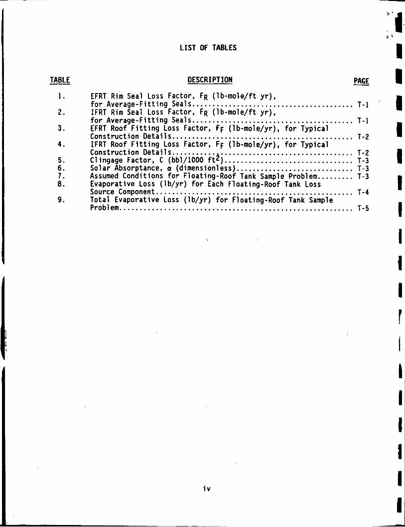
EFRT R i m Seal Loss Factor, FR ( lb -mole / f t y r ) , f o r Average-Fi t t ing Seals. ....................................... T - 1 IFRT R i m Seal Loss Factor, FR ( lb -mole / f t yr), f o r Ave rage- f i t t i ng Seals.. ...................................... T - 1 EFRT Roof f i t t i n g Loss Factor, FF ( lb-mole/yr), f o r Typica l Construct ion D e t a i l s ............................................. T-2 IFRT Roof F i t t i n g Loss Factor, FF (lb-mole/yr), f o r Typica l Construct ion Deta i l s . . ........ .*. ................................ T-2 Clingage Factor, C (bb1/1000 ft ) ................................ T-3 So la r Absorptance, Q (dimensionless). ............................ T-3 Assumed Condit ions f o r Float ing-Roof Tank Sample Problem.. ....... T-3 Evaporative Loss ( lb /y r ) f o r Each Float ing-Roof Tank Loss Source Component ................................................. T-4 To ta l Evaporative Loss ( l b / y r ) f o r Float ing-Roof Tank Sample Problem .......................................................... T-5
i v
I I 1 1 I I 1 1 1 I I
I I i I I I
i
-

m I I I I I I I
I I I I I
m
ABSTRACT
This year (1991) the American Petroleum Institute (API) completed the cycle of updating all three of the core evaporative loss publications that deal with aboveground storage tanks. 'These pub1 ications deal with evaporative losses from External Floating-Roof Tanks (EFRTs), Internal Floating-Roof Tanks (IFRTs) and Fixed-Roof Tanks (FRTs). The updated API evaporative loss publications are the result of an extensive API-sponsored laboratory and field testing program that included analytical developments .to model storage tank evaporative loss processes. These revised API publications now permit loss calculations to be made with greater detail and accuracy for alternative loss control options.
This paper gives an overview of the API-sponsored work and discusses the areas o f : (1) loss sources; (2) loss mechanisms; (3) loss measurement methods; (4) loss calculation methods;' (5) sample calculations; and (6) conclusions related to the impact that these updated publications will have on petroleum industry storage tank evaporative losses.
V

1 .O INTRODUCTION
The American Petroleum Institute (API) Committee on Evaporation Loss Measurement (CELM) prepares, maintains and revises, as required, all API publications that provide methods for calculating evaporative losses from the storage and transfer of petroleum 1 iquids.
API Publications 2517[1], 2518[2] and 2519[3] deal respectively with evaporative losses from External Floating-Roof Tanks (EFRTs), Fixed-Roof Tanks (FRTs) and Internal Floating-Roof Tanks (IFRTs). These three publications were originally issued in 1962 and were then intended to provide petroleum company operating personnel with a basis to evaluate the benefits associated with alternative product conservation techniques.
With the establishment of the U.S. Clean Air Act in 1970, attention was focused on atmospheric emissions from hydrocarbon sources. Recognizing that technological improvements in petroleum storage tank construction and operation had occurred since the time that the original evaporative loss data was obtained, the CELM was formally reorganized in 1974 to initiate a program to update these loss pub1 ications. A preliminary evaluation indicated that the then existing API evaporative loss calculation methods significantly overestimated hydrocarbon losses, or atmospheric emissions.
Initial API efforts were directed at updating API Publications 2517 and 2519, which deal with floating-roof tanks. More recent efforts have been directed at updating API Publication 2518, which. deals with fixed-roof tanks, and the Second Edition will be issued in the Fall of 1991. All of these efforts involved an extensive laboratory and field testing program that included analytical developments to model storage tank evaporative loss processes. The API results have also become the basis for the U.S. Environmental Protection Agency publication [4] on air pollutant emission factors.
This paper describes the efforts that were directed toward updating the API evaporative loss publications that deal with EFRTs, IFRTs and FRTs. An overview is given of:
.1-1

o Loss Sources o Loss Mechanisms o Loss Measurement Methods o Loss Calculation Methods o Sample Calculations
The A P I evaporative loss publications will soon be converted to metric units. This paper, however, presents the A P I loss calculation methods in the units currently used so that the description presented here may be compared directly with the current versions o f the A P I loss publications.
P 1 I 1 I I I I
1-2
1 I C I 8 8 8 6

i "I
0 1 I)
8 I I I I E I I I I I I I I I
2.0 LOSS SOURCES
A tank "loss source" may be def ined as a bas ic element o f the tank from which evaporative loss , o r atmospheric emissions, occurs. For each tank type, the p o t e n t i a l loss sources are:
External Float ing-Roof Tanks (EFRTs) o R i m Seals o Roof F i t t i n g s o Stock Clingage
I n t e r n a l Float ing-Roof Tanks (IFRTs) o R i m Seals o Roof F i t t i n g s o Roof Seams o Stock Clingage
Fixed-Roof Tanks (FRTs) o Roof F i t t i n g s
To b e t t e r understand these l o s s sources, i t i s h e l p f u l t o review some o f t h e loss- re la ted tank cons t ruc t ion d e t a i l s .
2.1 EFRT Loss Sources
Figures 1 and 2 show t y p i c a l EFRTs. EFRTs are v e r t i c a l c y l i n d r i c a l vessels which do n o t have a f i x e d r o o f over the t o p o f the tank, bu t which u t i l i z e an External F l o a t i n g Roof (EFR) t h a t r e s t s on the stock l i q u i d surface.
EFRs are c u r r e n t l y o f two general types:
o o
Pontoon F loa t ing Roof (see F igure 1) Double-Deck F loa t ing Roof (see Figure 2)
The pontoon f l o a t i n g r o o f incorporates buoyancy chambers t h a t a s s i s t i n keeping t h e r o o f f l o a t i n g , even under heavy water o r snow loads. One type of
2 - 1

design uses an annular r i n g o f pontoons around the ou ter per imeter o f the f l o a t i n g roo f . I n t h i s design, the center s ing le deck area i s designed t o ba l loon upward t o conta in stock vapors t h a t are generated from ambient heat ing o f the stock l i q u i d surface under the f l o a t i n g r o o f . The amount o f surface heating, however, i s reduced by the i n s u l a t i n g e f f e c t o f the double-deck i n the pontoon area and by the bal looning e f f e c t o f the center s i n g l e deck.
The double-deck f l o a t i n g r o o f incorporates two decks which cover the e n t i r e area o f the f l o a t i n g roo f . Ve r t i ca l bulkheads are used t o support the upper deck and t o d i v i d e the space between the decks i n t o separate l i q u i d - t i g h t compartments. The double-deck f l o a t i n g r o o f provides good s t a b i l i t y , but smal ler ra inwater load car ry ing capaci ty than the pontoon f l o a t i n g roo f . The top deck, which extends over the e n t i r e area o f the f l o a t i n g r o o f , provides an i n s u l a t i n g a i r space between the decks and thus minimizes heat ing o f the stock l i q u i d surface.
EFRs are t y p i c a l l y o f welded const ruct ion, and the r o o f seams are thus not a source o f evaporat ive loss.
2.1.1 EFRT R i m Seals
An EFRT r i m seal system consis ts o f e i t h e r one o r two separate seals. The lower, o r f i r s t seal, i s c a l l e d the pr imary seal; t h e upper, o r second seal, i s c a l l ed the secondary seal .
Figures 3 through 6 show t y p i c a l pr imary and secondary seal systems for EFRTs w i t h welded tank const ruct ion. For r i v e t e d tank const ruct ion, the only pr imary seal t y p i c a l l y used i s the mechanical-shoe primary seal due t o i t s good d u r a b i l i t y when s l i d i n g on a r i v e t e d surface.
? *
I I I 1
I I I
i ’
Two basic types o f primary seals are c u r r e n t l y i n widespread use f o r welded tank const ruct ion:
2-2

o Mechanical-Shoe Primary Seal (see Figure 3) o Resilient-Filled Primary Seal (see Figures 4, 5 and 6)
The resilient-filled primary seal may be mounted so that it either touches the liquid surface (i.e. liquid-mounted) or allows for a vapor space between the bottom of the seal envelope and the liquid surface (i.e. vapor-mounted). The resilient-filled seal may be filled with liquid, resilient foam, or gas to expand the seal envelope and maintain contact with the tank shell.
Two types of secondary seals are used:
o Shoe-Mounted Secondary Seal (see Figures 3, 4, 5 and 6) o Rim-Mounted Secondary Seal (not shown)
Shoe-mounted secondary seals are attached to the top of the shoe on a mechanical-shoe primary seal. They are effective in controlling emissions from gaps between the tank shell and the shoe, but do not' control emissions from the primary seal fabric. Rim-mounted secondary seals, however, are more effective in controlling emissions since they cover the entire rim space, and are more commonly used than shoe-mounted secondary seals.
Weather shields are sometimes used with a resilient-filled primary seal to protect the primary seal fabric from deterioration due to exposure to weather, debris and sunlight. Weather shields are usually of a leaf-type construction and have numerous radial joints to allow for movement of the floating roof and for irregularities in the tank shell. They are less effective than rim-mounted secondary seals in reducing evaporative loss due primarly to the unsealed radial joints.
2.1.2 EFRT Roof Fittinqs
As a result of an API-sponsored test program that was performed by CBI in 1984 [5 ,6 ] , a method was developed for calculating the evaporative loss from roof fittings commonly used on EFRTs. These results were incorporated into the Third Edition of API Publication 2517 [ l ] .
2-3

Roof f i t t i n g l oss f a c t o r s have been developed f o r the fo l l ow ing types of EFRT r o o f f i t t i n g s :
Access Hatch R i m Vent Gauge-Hatch/Sample We1 1 Vacuum Breaker
ROOF FITTING TYPE I FIGURE NUMBER I 7 8 9 10
Roof Leg Gauge-Float We1 1 Overflow Roof Dra in Unslot ted Guide-Pole Well S1 o t t e d Guide-Pol e/Sample We1 1
12 11 13 14 15
The above l i s t o f EFRT r o o f f i t t i n g types i s arranged i n order o f genera l ly increas ing evaporat ive l oss p o t e n t i a l . Section 3.4 o f Reference [l] provides a d e t a i l e d d e s c r i p t i o n o f each o f these r o o f f i t t i n g types.
2.1.3 EFRT Stock Clingage
Evaporative l oss from stock c l ingage occurs from an EFRT when stock i s withdrawn from the tank. As the f l o a t i n g r o o f l e v e l decreases, l i q u i d stock tends t o c l i n g t o the i ns ide surface o f the tank s h e l l . When the f l o a t i n g - r o o f r i m seal passes downward and exposes the wetted p o r t i o n o f t h e tank s h e l l ins ide surface, t h e v o l a t i l e p o r t i o n o f t h e stock c l ingage evaporates, r e s u l t i n g i n evaporat ive loss.
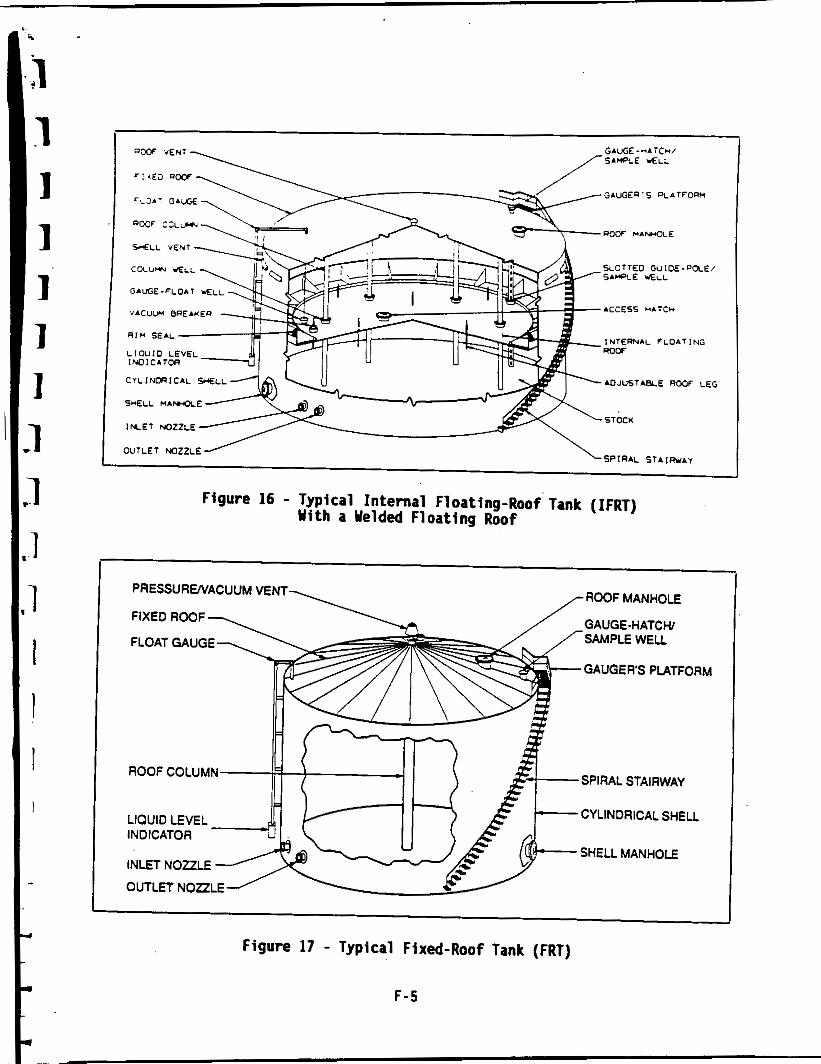
2.2 IFRT Loss Sources
F igure 16 shows a t y p i c a l IFRT. IFRTs are v e r t i c a l c y l i n d r i c a l vessels which have both a f i x e d r o o f over t h e top o f the tank and an I n t e r n a l F loa t ing Roof (IFR) t h a t r e s t s on the stock l i q u i d surface. The f i x e d r o o f may be e i t h e r "column supported" ( i .e . w i t h v e r t i c a l support columns i n the tank) o r " s e l f - supported" (i .e. wi thout v e r t i c a l support columns).
To reduce t h e occurrence of a flammable vapor -a i r m ix tu re i n the tank vapor space between the f l o a t i n g r o o f and the f i x e d roo f , vents are i n s t a l l e d a t the
2-4
-I I 1 1
I I I ! I I I 1 1 1 I I I I
i '
I

i i
top o f the tank she l l and on the f i xed r o o f t o provide na tura l c i r c u l a t i o n o f a i r through the vapor space. .Such tanks are r e f e r r e d t o as " f r e e l y vented"
I FRTs .
I F R s are c u r r e n t l y o f two general types:
o Welded Roofs o Bol ted Roofs ( i .e. Mechanical ly Joined Roofs)
Welded f l o a t i n g r o o f s cons is t o f s tee l p la tes which are welded together along t h e i r edges t o form a continuous deck. A v e r t i c a l r i m p l a t e i s provided around t h e per imeter o f the f l o a t i n g r o o f t o which t h e r i m seal system i s attached. F l o a t a t i o n occurs as a r e s u l t o f displacement o f the l i q u i d stock by the f l o a t i n g r o o f . F loa ta t ion may be enhanced by the use o f buoyant volumes on the top surface o f the f l o a t i n g roo f , and these may take the form o f an annular r i n g s i m i l a r t o a pontoon type EFR.
Bol ted f l o a t i n g r o o f s may be e i t h e r "non-contact" o r "contact" type. Non- contact b o l t e d f l o a t i n g r o o f s cons is t o f t h i n sheets ( t y p i c a l l y aluminum) which are mechanical ly ' fastened t o a support ing g r i d framework, below which t h e stock vapor i s contained. A v e r t i c a l r i m , o r s k i r t , extends down from the per imeter o f the f l o a t i n g r o o f i n t o the stock l i q u i d t o he lp conta in t h e stock vapors under the f l o a t i n g roo f . F loa ta t ion i s provided by the use o f sealed tubu la r pontoons t h a t are attached t o the underside o f the f l o a t i n g r o o f .
Contact b o l t e d f l o a t i n g r o o f s cons is t o f sealed panels which are mechanically j o i n e d along t h e i r edges t o form a continuous roo f . A v e r t i c a l r i m extends upward from the per imeter o f t h e f l o a t i n g r o o f t o which the r i m seal system i s attached. The r o o f panels f l o a t d i r e c t l y on the s tock l i q u i d surface and are t y p i c a l l y aluminum o r f iberg lass re in fo rced polyester s k i n sandwich panels w i t h e i t h e r a honeycomb aluminum core o r a r i g i d foam core.
Some IFRTs were o r i g i n a l l y constructed as EFRTs and were l a t e r converted t o IFRTs by covering them w i t h a f i x e d r o o f and adding s h e l l and r o o f vents t o provide v e n t i l a t i o n o f t h e tank vapor space. For t h i s type o f IFRT, the
2-5
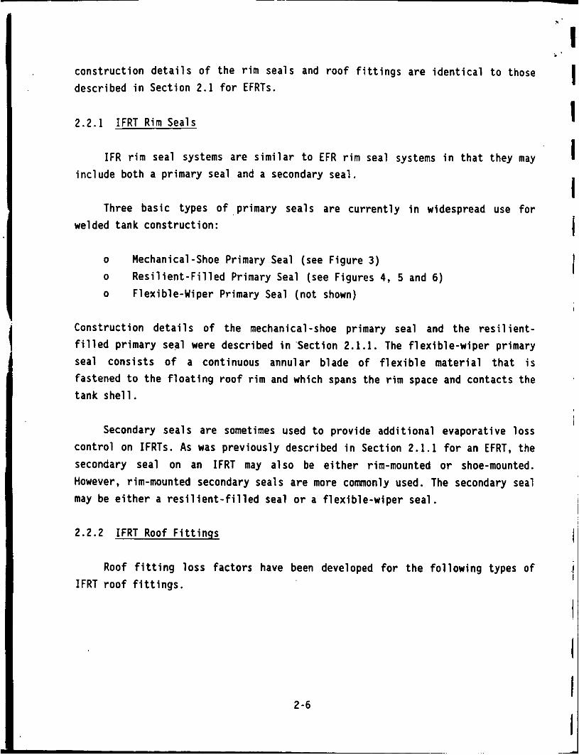
cons t ruc t ion d e t a i l s of the r i m seals and roof f i t t i n g s are i d e n t i c a l t o those descr ibed i n Sect ion 2.1 f o r EFRTs.
2.2.1 IFRT R i m S e a l s
I F R r i m seal systems are s i m i l a r t o EFR r i m seal systems i n t h a t they may inc lude both a pr imary seal and a secondary seal.
Three bas ic types of pr imary seals are c u r r e n t l y i n widespread use f o r welded tank cons t ruc t ion :
o Mechanical-Shoe Primary Seal (see Figure 3 ) o R e s i l i e n t - F i l l e d Primary Seal (see Figures 4, 5 and 6) o F lex ib le-Wiper Primary Seal (no t shown)
Construct ion d e t a i l s o f the mechanical-shoe primary seal and the r e s i l i e n t - f i l l e d pr imary seal were described i n .Section 2.1.1. The f l e x i b l e - w i p e r primary seal cons i s t s o f a continuous annular blade o f f l e x i b l e ma te r ia l t h a t i s fastened t o the f l o a t i n g r o o f r i m and which spans the r i m space and contacts the tank she1 1.
Secondary seals are sometimes used t o provide add i t i ona l evaporat ive loss con t ro l on IFRTs. As was prev ious ly described i n Section 2.1.1 f o r an EFRT, the secondary seal on an IFRT may a lso be e i t h e r rim-mounted or shoe-mounted. However, rim-mounted secondary seals a re more commonly used. The secondary seal may be e i t h e r a r e s i l i e n t - f i l l e d seal o r a f l e x i b l e - w i p e r seal.
2.2.2 IFRT Roof F i t t i n g s
Roof f i t t i n g l oss fac to rs have been developed f o r t h e f o l l o w i n g types o f IFRT r o o f f i t t i n g s .
2-6
, I I 1 I 1 I I I
I
I
I
I I I I

i , I
I ?
ROOF FITTING TYPE I FIGURE NUMBER
Vacuum Breaker Stub Dra in Access Hatch Roof Leg Gauge-Float We1 1 Column Well Unslot ted Guide-Pole Well S1 o t t e d Guide-Pole/Sample We1 1 Ladder We1 1
10
7 12 11 14 14 15
- -
- -
The above l i s t o f IFRT r o o f f i t t i n g types i s arranged i n order o f genera l l y increasing evaporative loss p o t e n t i a l . Sect ion 2.4 o f Reference [3 ] provides a d e t a i l e d d e s c r i p t i o n of each o f these r o o f f i t t i n g types. There are other types o f IFRT r o o f f i t t i n g s t h a t are used, bu t which do no t penetrate t h e IFR, and these are no t p o t e n t i a l sources o f evaporat ive loss.
2.2.3 IFRT Stock Clingage
Evaporative loss from stock c l lngage occurs from an IFRT when stock i s withdrawn from t h e tank. As the f l o a t i n g r o o f l e v e l decreases, l i q u i d stock tends t o c l i n g t o the i n s i d e surface o f t h e tank she l l and t o t h e surface o f any f i x e d r o o f support columns, guide poles and f i x e d ladders. When t h e f l o a t i n g - r o o f r i m seal o r column wel l cover passes downward and exposes the ' wetted por t ions o f t h e tank s h e l l and support columns, t h e v o l a t i l e p o r t i o n o f the stock c l ingage evaporates, r e s u l t i n g i n evaporat ive loss.
2.2.4 IFRT Roof Seams
IFRs are constructed w i t h e i t h e r welded seams o r bo l ted seams (i .e. mechanically j o i n e d seams). To the extent t h a t these b o l t e d seams are not vapor t i g h t , they are a source o f evaporative loss . Welded seams are vapor t i g h t and are thus no t a source o f evaporative loss.
2-7
I . .
2.3 FRT LOSS SOURCES
1 I I I I I
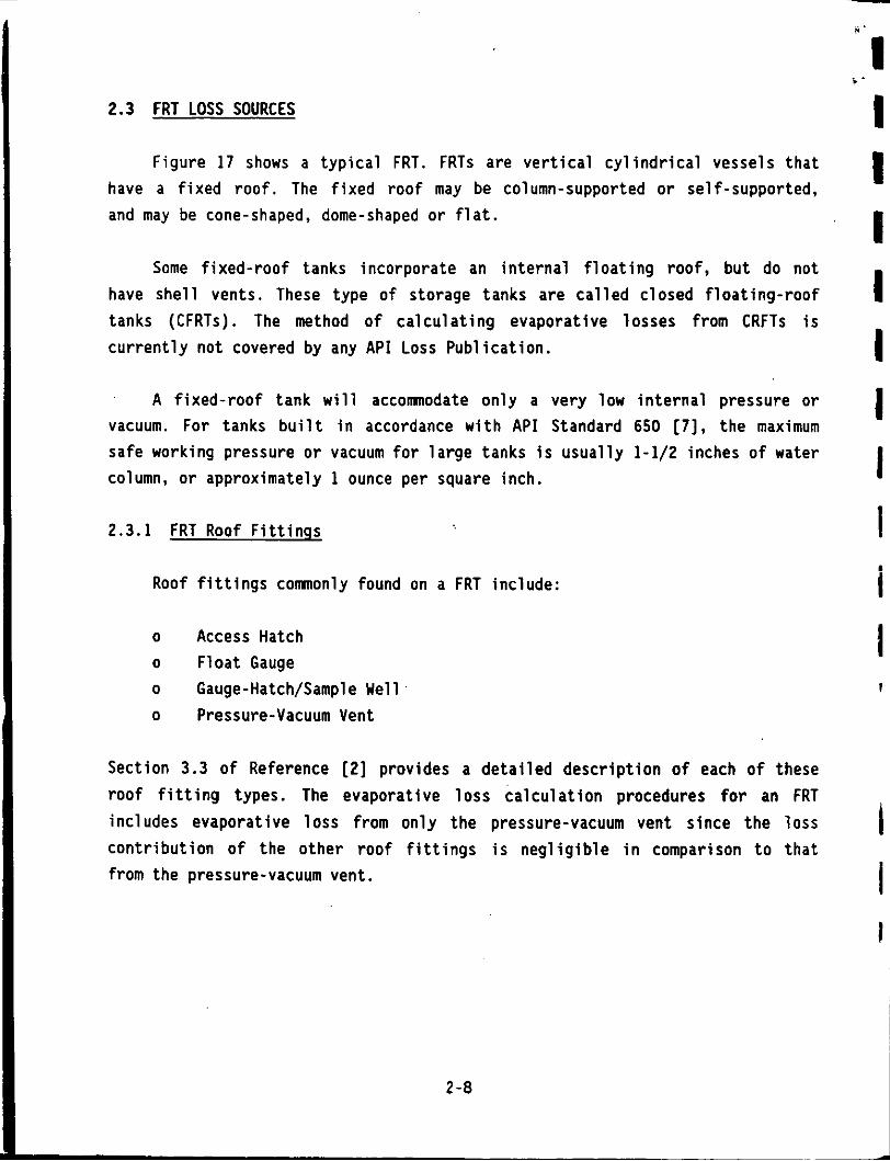
Figure 17 shows a typical FRT. FRTs are vertical cylindrical vessels that have a fixed roof. The fixed roof may be column-supported or self-supported, and may be cone-shaped, dome-shaped or flat.
Some fixed-roof tanks incorporate an internal floating roof, but do not have shell vents. These type of storage tanks are called closed floating-roof tanks (CFRTs). The method of calculating evaporative losses from CRFTs is currently not covered by any API Loss Publication.
A fixed-roof tank will accommodate only a very low internal pressure or vacuum. For tanks built in accordance with API Standard 650 [7], the maximum safe working pressure or vacuum for large tanks is usually 1-1/2 inches of water column, or approximately 1 ounce per square inch.
2.3.1 FRT Roof Fittings I i Roof fittings commonly found on a FRT include:
o Access Hatch o Float Gauge o Gauge-Hatch/Sample Well o Pressure-Vacuum Vent
1 I
Section 3.3 of Reference [2] provides a detailed description o f each of these roof fitting types. The evaporative loss calculation procedures for an FRT includes evaporative loss from only the pressure-vacuum vent since the loss contribution of the other roof fittings is negligible in comparison to that from the pressure-vacuum vent.
I I I
2-a

CENIEFI LEG
Figure 1 - Typical External Floating-Roof Tank (EFRT) Yi th a Pontoon Floating Roof
Figure 2 - Typical External Floating-Roof Tank (EFRT) Y i th a Double-Deck Floating Roof
F- I
‘ ~ 3 . - G A G
900F : ~ L W
S-ELL VENT
COL”*N WELL SLOTTED GuIOE-POLEI
GALGE -FLOA 7
VACUUM BREAKER rCCES5 *&TC*
ROOF W A W L E
S I P L E WELL
INTERNAL FLOATING R O W
CYLINORICAL %ELL
S M L L n . W E
I N E T NOZZLE
ADJUSTABLE R M f LEG
srom
Figure 16 - Typical Internal Floating-Roof Tank (IFRT) With a Welded Floating Roof
SPIRAL STAIRWAY
CYLINDRICAL SHELL INDICATOR
SHELL MANHOLE
LIQUID LEVEL 1 /E INLET NOZZLE - OUTLFT NOZZLE
Figure 17 - Typical Fixed-Roof Tank (FRT)
F-5
.
EVAPORATIVE LOSS FROM STORAGE TANKS
BY:
ROYCE J. LAVERMAN CHICAGO BRIDGE & IRON COMPANY
PLAINFIELD, ILLINOIS RESEARCH CENTER
PRESENTED AT:
THE FOURTH OIL Loss CONTROL CONFERENCE
"REAL AND APPARENT LOSSES IN REFINING AND STORAGE If
THE INSTITUTE OF PETROLEUM LONDON, UNITED KINGDOM
OCTOBER 30-3 1, 199 1
TECHNICAL PUBLICATION NUMBER CBT-5562

3.0 LOSS MECHAN1SM-S
A storage tank " loss mechanism" may be def ined as a physical o r chemical process involved i n the evaporative l o s s o f stock. For t h e EFRT, I F R T and FRT loss sources l i s t e d i n Section 2, several loss mechanisms have been i d e n t i f i e d
[61:
o B o i l i n g o Breathing o Clingage o Convection o Desorption o D i f f u s i o n o Displacement o Permeation o Wicking
Generally, losses from a p a r t i c u l a r l o s s source invo lve several l o s s mechanisms act ing simultaneously, and i t i s d i f f i c u l t when i n t e r p r e t i n g l o s s measurement data t o separate the i n d i v i d u a l c o n t r i b u t i o n o f each l o s s mechanism. However, f o r purposes o f b e t t e r understanding t h e process o f evaporat ive l o s s and i t s associated l o s s parameters, it i s usefu l t o have some understanding o f these loss mechanisms.
Operation o f a storage tank i s genera l l y d iv ided i n t o two modes:
o Standing Storage o Working Storage
I n standing storage, s tock does not flow i n t o o r ou t o f the storage tank; i n working storage, s tock does f low i n t o o r ou t o f t h e storage tank. The loss sources and loss mechanisms involved i n these two modes o f operat ion are not the same.
3 - 1

3.1 B o i l i n g I
B o i l i n g occurs when the stock surface t r u e vapor pressure equals o r exceeds atmospheric pressure, and involves the rapid evo lu t i on o f vapor from the l iquid surface.
Although b o i l i n g i s a po ten t i a l l oss mechanism, storage tanks are normally operated i n a manner so as t o avoid a b o i l i n g product. For t h i s reason, the A P I loss c a l c u l a t i o n methods described i n Sections 5 and 6 are not s u i t a b l e f o r use w i t h b o i l i n g o r unstable stocks.
3.2 Breath ing
Breath ing i s the process i n which stock vapors are expel led from an enclosed volume that i s i n communication with the s tock l iquid surface, and i s due t o e i t h e r a vapor temperature increase, evaporat ion f rom t h e s tock l iquid surface o r a barometr ic pressure decrease.
Breathing can occur, f o r example, i n t h e vapor space o f a FRT dur ing standing storage. F igure 18 i l l u s t r a t e s t h e d a i l y , ambient heat ing-re la ted, breath ing l oss mechanism on a FRT t h a t i s p a r t i a l l y f i l l e d w i t h a v o l a t i l e l i q u i d stock and i s equipped w i t h a pressure-vacuum vent. During the d a i l y ambient heat ing cyc le , t h e gas mixture i n the tank vapor space i s heated from a minimum temperature cond i t i on t o a maximum temperature cond i t ion . Vapor i s vented from t h e tank vapor space when the .vapor space pressure increases t o the pressure s e t t i n g o f the pressure-vacuum vent, r e s u l t i n g i n evaporat ive loss.
As the gas mix tu re i n the tank vapor space i s cooled from a maximum temperature cond i t i on t o a minimum temperature condi t ion, a i r i s admitted t o the tank vapor space when t h e pressure decreases t o the vacuum s e t t i n g o f the pressure-vacuum vent. Evaporation o f s tock occurs from the l i q u i d surface as the stock t r i e s t o sa tura te the a i r t h a t was admitted t o t h e tank vapor space. T e s t data i nd i ca tes t h a t there t y p i c a l l y i s a reg ion a t the top o f the tank vapor space near the pressure-vacuum vent where the re i s a s i g n i f i c a n t concentrat ion grad ien t . The vented gas i s t y p i c a l l y no t saturated ( i .e.
3-2
-1 I 1 I 4 I 1 I 1 0 1 I 1 I t f 1 I l

contains less stock vapor per unit volume than the gas immediately above the 1 iquid surface).
3.3 Clingage
Clingage involves the tendency for liquid stock to adhere t o a surface once it has had contact with that surface.
Clingage can occur, for example, when stock is withdrawn from an EFRT or IFRT. As the floating roof level decreases, liquid stock tends to cling to the inside surface of the tank shell and to the fixed roof vertical support columns. When the floating roof passes downward and exposes these areas, the volatile portion of the stock cl ingage rapidly evaporates, resulting in evaporative 1 oss.
3.4 Convection
Convection is the process in which stock vapors are set into motion by temperature and/or pressure differences.
Convection can occur, for example, in the rim space around an EFRT. Figure 19 illustrates the wind-related convection loss mechanism on an EFRT with a vapor-mounted resilient-filled seal. As the wind flows over the floating roof, a pressure gradient is generated above the rim seal, with a higher pressure existing above the seal on the downwind side of the floating roof than on the upwind side. As a result of this pressure gradient, air tends to flow downward past the seal on the downwind side, flow circumferentially around the rim vapor space below the primary seal, and then flow upward past the seal on the upwind side of the floating roof. As the air flows circumferentially around the rim vapor space, it tends to become saturated with stock vapor. This vapor is then emitted with the air vented on the upwind side of the floating roof, resulting 'in evaporative loss.
3-3
3.5 Desorpt ion
Desorpt ion i s the process i n which d isso lved gases come out o f s o l u t i o n due t o a 1 i q u i d temperature increase o r a barometr ic pressure decrease.
Desorption can occur, f o r example, i n the r i m space around a f l o a t i n g roof. L iqu id stocks may conta in some amount o f d isso lved v o l a t i l e gases. As the stock temperature increases o r the barometric pressure decreases, the amount o f gas t h a t can be d isso lved i n the stock w i l l decrease and some gas w i l l come out o f so lu t i on , r e s u l t i n g i n evaporat ive loss .
3.6. D i f f u s i o n
Vapor d i f f u s i o n i s the process i n which components i n a vapor s t a t e tend t o d i s t r i b u t e equa l ly throughout the vapor space.
Vapor d i f f u s i o n can occur, f o r example, i n the gaps o f a mechanical-shoe pr imary seal on an EFRT o r IFRT. I n the narrow v e r t i c a l gap between the tank s h e l l and the m e t a l l i c shoe, upward d i f f u s i o n o f the stock vapor can occur, r e s u l t i n g i n evaporat ive loss. Normally, however, vapor convect ion a lso occurs i n these narrow v e r t i c a l gaps, and the combined e f f e c t can r e s u l t i n much higher evaporat ive l o s s r a t e than the loss r a t e due t o d i f f u s i o n alone.
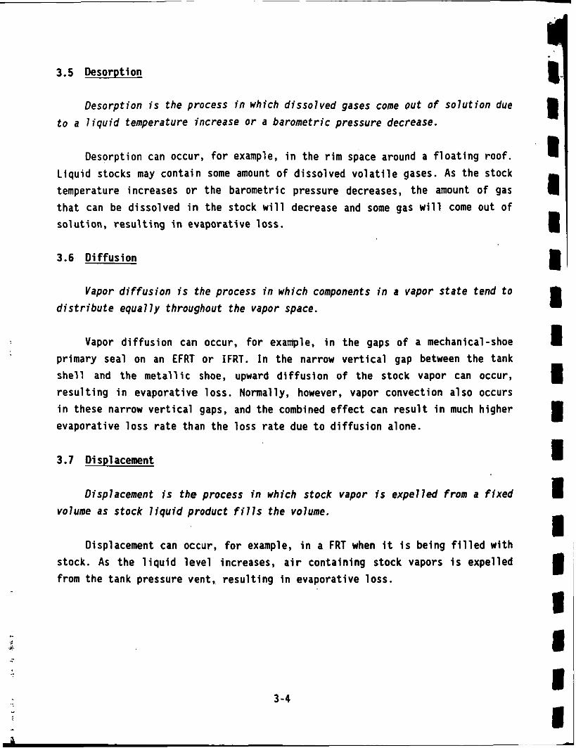
3.7 Displacement
Displacement i s t h e process i n which stock vapor i s expe l led f rom a f i x e d volume as s tock l iquid product f i l l s the volume,
Displacement can occur, f o r example, i n a FRT when i t i s being f i l l e d w i th stock. As the l i q u i d l e v e l increases, a i r conta in ing stock vapors i s expel led from the tank pressure vent, r e s u l t i n g i n evaporat ive loss.
3-4

3.8 Permeation
Permeation i s the process i n which stock vapor d i f f u s e s through a s o l i d mater ia l due t o a concentrat ion d i f f e r e n c e across the mater ia l .
Permeation can occur, fo r example, through the seal envelope of a r e s i l i e n t - f i l l e d primary seal. The seal envelope mater ia l i s normal ly a f l e x i b l e coated f a b r i c sheet (e.g. polyurethane coated ny lon f a b r i c ) . 'These mater ia ls may be somewhat permeable t o product vapors. Since a higher concentrat ion of vapor i s normally present below t h e seal, vapors tend t o permeate through t h e seal envelope mater ia l , r e s u l t i n g i n evaporat ive loss .
3.9 Nick ing
l ick ing i s the process i n which a s tock l iqu id tends t o f l o w upward between two c l o s e l y spaced surfaces by c a p i l l a r y a c t i o n due t o sur face tens ion forces.
Wicking can occur, f o r example, with a l iquid-mounted r e s i l i e n t - f i l l e d primary seal on an EFRT o r IFRT. The pr imary seal envelope i s normally i n in t imate contact w i t h t h e ins ide surface o f the tank s h e l l . I f the primary seal i s l iquid-mounted, the stock l i q u i d l e v e l i n the r i m space may be located i n the area o f seal - t o - s h e l l contact . Depending upon the surface c h a r a c t e r i s t i c s o f the seal envelope and tank she l l , c e r t a i n h igh surface tens ion stocks may have a tendency t o f l o w upward i n the s e a l - t o - s h e l l contact area due t o wicking, r e s u l t i n g i n evaporat ive loss .
3-5

I I I I I I I I I
I I
1 a
4.0 LOSS MEASUREMENT METHODS
Four types of evaporative loss measurement methods were used to obtain the test data for Preparing the latest editions of API Publications 2517 [I], 2518 [2], and 2519 [31, for EFRTs, FRTs and IFRTs, respectively. These evaporative loss measurement methods are:
o Field Tank Tests o Pilot Tank Tests o Wind Tunnel Tests o Stock Clingage Tests
4.1 Field Tank Tests
Two types of test methods were used on field tanks:
o o
Stock Density Change Method (used on EFRTs and .IFRTs) Vented Vapor Measurement Method (used on FRTs).
4.1.1 Stock Density Chanqe Method
The stock density change method was used to measure the standing storage loss from two field EFRTs and one field IFRT [ 9 ] . This method was also used in tests performed on the pilot test tank [10,11]. In this method, the stock density is accurately measured over a period of time. For multicomponent hydrocarbon stocks, the 1 ighter components tend to evaporate faster, thus resulting in a gradual increase in the density o f the remaining stock.
Figure 20 is a schematic of the stock density change method that was used in the API-sponsored field tank tests [9]. In these tests, three tanks were tested simultaneously. A mobile van housing the density meter and associated instrumentation was moved from one tank to another to sample each tank weekly over a period of about 120 days. Each tank was sampled at approximately 20 locations in the stock to determine the average stock density. A Mettler-Paar Model DMA 60/601 high-precision density meter was used to measure the density o f stock samples to seven significant figures. This high degree of precision was
4-1

necessary because evaporat ive loss .
o f the small change Figure 21 i l l u s t r a t e s
i n stock dens i ty associated w i t h the how the average stock dens i ty changed
w i th time dur ing one o f the f i e l d tank t e s t s [9].
The s tock dens i t y change measured i n the f i e l d tank t e s t s was converted t o evaporat ive l o s s by using labora tory measurements o f the stock p roper t i es tha t included the evaporat ive density-change f a c t o r [9].
4.1.2 Vented Vapor Measurement Method
The vented vapor measurement method was used. t o measure the evaporative l o s s from one f i e l d FRT s t o r i n g f u e l o i l [12] as p a r t o f an API-sponsored t e s t program. A s i m p l i f i e d version o f the vented vapor measurement method was a l s o used i n e a r l i e r f i e l d tank t e s t s on 21 FRTs s t o r i n g crude o i l s , d i s t i l l a t e s and fue l o i l [13] and on 6 FRTs s t o r i n g petrochemicals [14]. I n t h i s method, the evaporat ive l o s s i s determined from measurements o f t h e volume and composition of the vapor expel led from the FRT p res iu re vent.
F igure 22 i s a schematic diagram o f the t e s t arrangement t h a t was used on a 20 f o o t diameter f i e l d tank. The volume o f vapor expel led through the pressure vent and t h e volume o f a i r inhaled through the vacuum vent were measured using d ry gas meters. The pressure vent gas meter was placed i n an insu la ted and heated enclosure t o prevent hydrocarbon condensation i n the meter.
I n a d d i t i o n t o sampling the vapor which was passed through the pressure vent gas meter, the tank vapor space was sampled t o determine the v e r t i c a l p r o f i l e o f hydrocarbon concentrat ion. Ten v e r t i c a l po in ts a t 3 d i f f e r e n t l oca t i ons were sequen t ia l l y sampled ( i .e . a t o t a l o f 30 vapor sample po in ts ) t o determine t h e d a i l y v a r i a t i o n i n the concentrat ion p r o f i l e . These vapor samples were analyzed f o r t o t a l hydrocarbon concentrat ion and p e r i o d i c a l l y a complete component ana lys is was performed us ing a gas chromatograph.
The v e r t i c a l temperature p r o f i l e i n the vapor space was measured w i th 20 v e r t i c a l thermocouples a t 3 d i f f e r e n t loca t ions . I n add i t ion , the ambient temperature, tank r o o f temperature and the tank she1 1 temperature were measured.
4 -2
i
-,a 1 1 1 I li 1 I I I I I I I I II 1 I I -

An extensive data a c q u i s i t i o n system was used t o a i d i n recording and analyzing the t e s t r e s u l t s .
The d a i l y evaporative loss o f the tank was determined by summing the hour ly amounts o f hydrocarbon vapor expel led from the tank pressure vent.
4.2 P i l o t Tank Tests
A P i l o t Tank Test F a c i l i t y was used t o study evaporative losses from both EFRTs [15] and IFRTs [16] . Figure 23 i s a photograph and F igure 24 i s a schematic diagram o f the C B I 20 f o o t diameter P i l o t Tank Test F a c i l i t y .
I n t h i s t e s t method, a c o n t r o l l e d q u a n t i t y o f a i r i s passed through the space between a f l o a t i n g r o o f and a . f i xed r o o f t o s imulate t h e e f f e c t o f ambient wind. For EFRT tes ts , t h e a i r f low r a t e was c o n t r o l l e d t o s imulate the e f f e c t o f ambient wind f low ing across an EFRT. For IFRT tests , t h e a i r f low r a t e was c o n t r o l l e d t o s imulate the e f f e c t o f ambient wind blowing through t h e s h e l l vents o f an IFRT. Wind tunnel t e s t data and f i e l d tank t e s t data were used t o es tab l i sh the p i l o t tank wind speed c a l i b r a t i o n f o r an EFRT [17,18] and an IFRT [19] . The increase i n t o t a l hydrocarbon concentrat ion o f t h e a i r passing through t h e p i l o t tank i s measured, and t h e evaporative loss r a t e may then be d i r e c t l y ca lcu lated.
The main advantage o f the p i l o t tank t e s t method i s t h a t t h e , t e s t condi t ions may be c o n t r o l l e d and systemat ica l ly var ied t o study t h e e f f e c t o f s p e c i f i c parameters on evaporat ive loss. Some o f the t e s t condi t ions t h a t were systemat ica l ly var ied inc lude [IS] :
Tank Construct ion Condit ions: o Welded and Riveted Tank Shel l Construct ion
F loa t ing Roof Construct ion Conditions: o EFRT and IFRT Primary Seal Type o o EFRT and IFRT Primary Seal Gaps
EFRT and IFRT Primary Seal Mounting Type
4 -3

o EFRT and IFRT Secondary Seal Type o EFRT and IFRT Secondary Seal Mounting Type o EFRT and IFRT Secondary Seal Gaps
Meteorological Conditions:
o Ambient Wind Speed o Ambient Temperature
Product Conditions: o Product Vapor Pressure o Product Types Inc lud ing:
- Gasoline, - Crude O i l , - Normal Hexane, - Benzene, - Normal Octane, and - Mixtures o f Propane and Nohnal Octane.
Most o f the t e s t work was performed us ing mixtures o f propane and normal octane, where the propane content was sys temat ica l l y c o n t r o l l e d and var ied t o determine the e f f e c t o f vapor pressure on evaporat ive loss .
4.3 Wind Tunnel Tests
A spec ia l Wind Tunnel T e s t F a c i l i t y was constructed by CBI and used i n an API-sponsored t e s t program [ZO] t o measure t h e evaporat ive l o s s o f EFRT roof f i t t i n g s . F igure 25 i s a photograph and F igure 26 i s a schematic diagram o f the Wind Tunnel Test F a c i l i t y . The wind tunnel i s 29 f e e t long and has a 3 f o o t square cross sect ion. I t incorporates 4 t e s t sect ions, each 5 f e e t long, f o r simultaneously t e s t i n g 4 separate r o o f f i t t i n g s .
Each o f the r o o f f i t t i n g s tes ted was a f u l l - s c a l e r o o f f i t t i n g t h a t was mounted on a s tock l i q u i d rese rvo i r which res ted on a d i g i t a l p la t fo rm scale. The r o o f f i t t i n g s extended above the t e s t rese rvo i r s i n t o the wind tunnel . The ambient wind e f f e c t on the exposed p o r t i o n o f the r o o f f i t t i n g s was simulated by the a i r f l ow through the wind tunnel . Air from a blower passed through a
4-4
‘1 I 1 1 i I 1 I c
1 s I I I I
i
t r a n s i t i o n sect ion and an a i r d i s t r i b u t i o n sect ion p r i o r t o passing over the roof f i t t i n g s . AS evaporative loss occurred dur ing a p a r t i c u l a r t e s t , t h i s loss was d i r e c t l y measured by the weight change recorded f o r each o f t h e plat form scales.
Evaporative l o s s measurements were performed a t simulated wind speeds up t o 14 mi/hr. A t o t a l o f 8 ser ies o f tes ts , each ser ies w i t h 4 d i f f e r e n t r o o f f i t t i n g s , were performed on t h e most common r o o f f i t t i n g s used on current EFRTs.
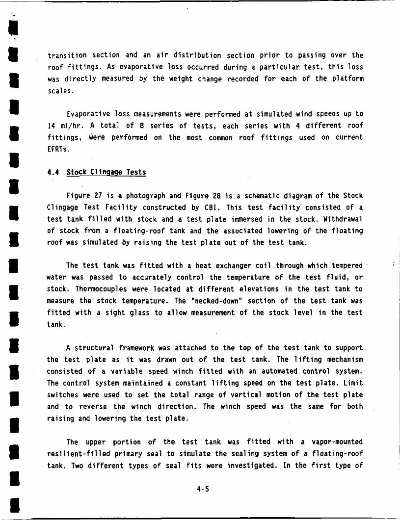
4.4 Stock Clingage Tests
Figure 27 i s a photograph and Figure 28 i s a schematic diagram o f the Stock Clingage Test F a c i l i t y constructed by C B I . This t e s t f a c i l i t y consisted o f a t e s t tank f i l l e d w i t h stock and a t e s t p l a t e immersed i n t h e stock. Withdrawal o f stock from a f l o a t i n g - r o o f tank and t h e associated lowering o f t h e f l o a t i n g r o o f was simulated by r a i s i n g the t e s t p l a t e out o f the t e s t tank.
The t e s t tank was f i t t e d w i t h a heat exchanger c o i l through which tempered water was passed t o accurately cont ro l t h e temperature o f t h e t e s t f l u i d , o r stock. Thermocouples were loca ted a t d i f f e r e n t e levat ions i n t h e t e s t tank t o measure the stock temperature. The "necked-down" sect ion o f t h e t e s t tank was f i t t e d w i t h a s i g h t g lass t o a l low measurement o f the stock l e v e l i n the t e s t tank.
A s t r u c t u r a l framework was attached t o the t o p o f the t e s t tank t o support the t e s t p l a t e as it was drawn out o f the t e s t tank. The l i f t i n g mechanism consisted o f a v a r i a b l e speed winch f i t t e d wi th an automated c o n t r o l system. The c o n t r o l system maintained a constant l i f t i n g speed on t h e t e s t p la te . L i m i t switches were used t o se t t h e t o t a l range o f v e r t i c a l motion o f t h e t e s t p l a t e and t o reverse t h e winch d i r e c t i o n . The winch speed was the same f o r both r a i s i n g and lower ing t h e t e s t p l a t e .
The upper p o r t i o n o f the t e s t tank was f i t t e d w i t h a vapor-mounted r e s i l i e n t - f i l l e d primary seal t o s imulate the seal ing system o f a f l o a t i n g - r o o f tank. Two d i f f e r e n t types o f seal f i t s were invest igated. I n t h e f i r s t type o f
4 - 5

sea l f it, the re was no gap between the seal and the t e s t p la te , r e s u l t i n g i n e f f e c t i v e wip ing ac t i on on the t e s t p l a t e . I n the second type o f seal f it, there was a gap between the seal and the t e s t p l a t e t o s imulate s i t u a t i o n s on a f l o a t i n g - r o o f tank where there i s not a t i g h t f i t between seal and s h e l l .
The t e s t p l a t e simulated the s h e l l o f a f l o a t i n g - r o o f tank. The t e s t p l a t e was approximately 20 f e e t long by 12 inches wide by 1/4 inch t h i c k and was made o f carbon s tee l . Both sides o f the t e s t p l a t e were t e s t surfaces. The edges o f the t e s t p l a t e were beveled t o permi t complete wip ing o f the surfaces and t o minimize s tock c l ingage t o the edges o f the p l a t e as i t passed by the seals. The t e s t p l a t e was ra ised and lowered through a range o f 16 f e e t - 9 inches. Since the p l a t e was 1 f o o t wide and both sides were i n contact w i t h the stock and the seals, the t o t a l wiped surface area f o r each p l a t e was 33.5 square fee t . Two d i f f e r e n t t e s t p l a t e surface condi t ions were examined: a clean surface and a l i g h t l y rus ted surface.
The evaporat ive l o s s due t o s h e l l c l ingage was ,determined by measuring the decrease i n s tock l e v e l i n the t e s t tank a t t h e necked-down sect ion. The t e s t p l a t e was ra i sed out and lowered back i n t o the t e s t tank a t a continuous r a t e o f about 6 in/min. This process was performed f a r a t l e a s t 20 cycles.
Two d i f f e r e n t stocks were tested: octane [21] and a low-v iscos i ty , U.S. mid-cont inent, type A-B sweet crude o i l 1221.
4-6
'I 1 A
4 1 I
I I i 1 f 1 I I I I t 1
a
.
5.0 EFRT AND IFRT LOSS CALCULATION METHODS
This sect ion presents a b r i e f o u t l i n e of the evaporat ive loss c a l c u l a t i o n methods f o r both an EFRT and an IFRT.
The cur ren t A P I loss c a l c u l a t i o n methods f o r an EFRT, IFRT and FRT are contained i n the f o l l o w i n g A P I evaporative loss publ icat ions:
TANK TYPE A P I PUBLICATION EFRT A P I Pub l ica t ion 2517, Th i rd Edi t ion, February 1989 FRT A P I Pub l ica t ion 2518, Second Edi t ion, F a l l 1991 IFRT A P I Pub l ica t ion 2519, Th i rd Edi t ion, June 1983
Due t o the s i m i l a r i t i e s between the evaporative l o s s c a l c u l a t i o n methods f o r an EFRT and IFRT, they are described together i n Section 5. The evaporative l o s s c a l c u l a t i o n method f o r a FRT i s s i g n i f i c a n t l y d i f f e r e n t from t h a t f o r an EFRT and IFRT due t o the d i f f e r e n t loss mechanisms involved. Therefore, the evaporative loss c a l c u l a t i o n method f o r a FRT i s described i n Sect ion 6.
It i s no t poss ib le t o g i v e here a l l t h e d e t a i l s f o r each c a l c u l a t i o n method, and before using these methods i t i s recommended t h a t a care fu l review be made o f the above A P I publ icat ions. The f o l l o w i n g summary i s intended only t o i n d i c a t e the basic format o f each method and the l o s s parameters involved i n each method.
The l i m i t a t i o n s under which the A P I evaporative l o s s methods can be used are l i s t e d i n each o f the appropr iate A P I publ icat ions. Some o f these l i m i t a t i o n s p e r t a i n t o the appl icable range o f tank diameters, stock types, stock vapor pressures, wind speeds and l o s s est imat ion t ime periods. Also, t h e methods are not s u i t a b l e t o estimate evaporat ive losses from unstable o r b o i l i n g stocks.
The cur ren t loss c a l c u l a t i o n methods f o r EFRTs and IFRTs are d e t a i l e d and take i n t o account the independent c o n t r i b u t i o n o f each l o s s source t o the t o t a l loss f o r gener ic equipment types. This i s usefu l i n i d e n t i f y i n g t h e s i g n i f i c a n t
5-1

I parameters a f f e c t i n g the t o t a l l oss f o r a s p e c i f i c tank as we l l as i n evaluat ing the ef fect iveness o f a l t e r n a t i v e l o s s reduc t ion opt ions.
The loss c a l c u l a t i o n equations are based on the use of both theo re t i ca l models o f the s i g n i f i c a n t l oss mechanisms and experimental t e s t r e s u l t s designed t o i s o l a t e the e f f e c t o f the s i g n i f i c a n t l oss parameters.
5.1 EFRT and IFRT Loss Equations I
Tota l Loss I
The t o t a l loss, LT, i s the sum o f the withdrawal loss , Lw, and the standing storage loss, Ls, as shown i n Equation 1:
LT = Lw t Ls
Withdrawal Loss
The withdrawal loss, Lw, may be ca lcu la ted from Equation 2:
The withdrawal loss , Lw, w i l l vary w i t h tank operat ing prac t ices . Industry-wide experience has found t h a t t h i s l o s s i s o f t e n small, except i n cases of high throughput t h a t r e s u l t i n f requent tank turnovers ( i .e. g rea te r than about 10 turnovers per year) o r i n cases o f a l a r g e cl ingage fac to r , such as f o r high v i s c o s i t y crude o i l .
The number o f columns, Nc, i s 0 f o r an EFRT.
5-2

Standinq Storaqe Loss
The standing storage loss, Ls, may be calculated from Equation 3:
In the Third Edition of API Publication 2517 [ l ] , the standing storage loss, Ls, calculation method was modified to incorporate the total roof fitting loss factor, FF. Previously, the evaporative loss contribution of the roof fittings was assumed to be negligible.
Equation 3 involves the product of two terms:
First Term, (FR D t FF t FD)
The first term pertain only to floating-roof construction parameters (e.g. rim seal system type, roof fitting types, roof seam,construction type) and environmental parameters (e.g. ambient wind speed, V ) .
Second Term, (P* MV KC)
The second term pertain only to stock characteristics (e.9. vapor pressure, vapor molecular weight, stock type).
The vapor pressure function, P*, is defined by Equation 4.
I' t [I - \]o.5]2
5-3

i
where t h e s tock vapor pressure, P, i s determined a t t h e s tock l i q u i d bu lk temperature, Tg.
5.2 R i m Seal Loss Factor
The r i m seal l o s s factor , FR, fo r EFRTs has been found t o depend upon the tank cons t ruc t ion type, r i m seal system type, seal fit, and ambient wind speed, V. F igures 29 through 32 present the r i m seal l o s s f a c t o r f o r d i f f e r e n t seal ing systems as a f u n c t i o n o f wind speed, V, between 2 and 15 mi/hr ( i .e . t h e wind speed range o f t h e t e s t data). Table 1 l i s t s the EFRT r i m seal l o s s f a c t o r f o r a v e r a g e - f i t t i n g seals a t 5, 10 and 15 mi/hr wind speeds. The loss . con t ro l e f fec t i veness o f d i f f e r e n t r i m seal systems can be compared by comparing the r i m seal l o s s fac to rs , FR, a t the same wind speed, V .
The r i m seal l o s s f a c t o r , FR, f o r IFRTs has been found t o depend on ly upon the tank cons t ruc t ion type, r i m seal system type and seal f it. It does not depend upon ambient wind speed, V, as does t h e r i m seal l o s s f a c t o r f o r EFRTs. Table 2 l i s t s t h e IFRT r i m seal l o s s f a c t o r f o r d i f f e r e n t r i m seal systems w i t h a v e r a g e - f i t t i n g seals.
The r i m seal l o s s f a c t o r f o r EFRTs found i n Table 1 may be compared w i t h those f o r IFRTs found i n Table 2. For t h e same r i m seal type, t h e r i m seal l o s s fac to r i s genera l l y l e s s f o r an IFRT. This i s most ev ident f o r pr imary-only r i m seals, where t h e ambient wind p lays a s i g n i f i c a n t r o l e i n evaporat ive loss from EFRT r i m seals.
5.3 Roof F i t t i n g Loss Factor
The r o o f f i t t i n g l o s s fac to r , FF, f o r EFRTs has been found t o depend upon r o o f f i t t i n g type, r o o f f i t t i n g cons t ruc t ion d e t a i l s , and ambient wind speed, V. Table 3 l i s t s t h e EFRT r o o f f i t t i n g l o s s f a c t o r f o r t y p i c a l r o o f f i t t i n g cons t ruc t ion d e t a i l s a t 5, 10 and 15 mi/hr wind speeds.
The r o o f f i t t i n g l o s s fac to r , FF, f o r IFRTs has been found t o depend upon on ly t h e r o o f f i t t i n g type and r o o f f i t t i n g cons t ruc t ion d e t a i l s . I t does not
depend upon t h e ambient wind speed, V, as does t h e r o o f f i t t i n g l o s s f a c t o r f o r
r I I I I 1 I I
~
5-4
EFRTs. Table 4 l i s t s the IFRT r o o f f i t t i n g l o s s f a c t o r f o r t y p i c a l r o o f f i t t i n g construct ion d e t a i l s .
The r o o f f i t t i n g loss f a c t o r f o r EFRTs found i n Table 3 may be compared w i t h those f o r IFRTs found i n Table 4 . For t h e same r o o f f i t t i n g type, the roof
f i t t i n g loss factor i s genera l ly less f o r IFRTs. This i s most ev ident fo r the r o o f f i t t i n g l o s s fac to r o f a s l o t t e d guide-pole/sample w e l l .
5.4 Roof Seam Loss Factor
The r o o f seam loss fac to r , FD, accounts f o r the evaporat ive l o s s t h a t occurs from seams on IFRT f l o a t i n g roo fs and may be ca lcu la ted from Equation 5:
Fo = KO So 0' (5)
Since the r o o f seam l o s s factor , FD. i s p ropor t iona l t o the square o f the tank diameter, 0, the evaporative l o s s c o n t r i b u t i o n from the r o o f seams can be s i g n i f i c a n t f o r l a r g e diameter tanks.
The r o o f seam l o s s fac to r , KO, i s 0 l b -mo le / f t yr f o r welded f l o a t i n g - r o o f seams and 0.34 lb -mole/ f t yr f o r bo l ted ( i .e . mechanical ly jo ined) f l o a t i n g - r o o f seams.
The f l o a t i n g r o o f seam length fac to r , Sg, depends upon t h e f l o a t i n g r o o f const ruct ion type. A value o f 0.20 ft/ft* can be used f o r t y p i c a l f l o a t i n g r o o f construct ion.
5.5 Product Factor
The product f a c t o r , KC, accounts f o r t h e e f f e c t o f d i f f e r e n t types o f l i q u i d stocks on evaporat ive loss from EFRTs o r IFRTs dur ing tank working. Product f a c t o r s have been developed f o r the f o l l o w i n g types o f stocks:
5 - 5

STOCK TYPE Crude O i l s Refined Petroleum Stocks Single-Component Petrochemical Stocks
Icr (dimensionless1 0.40 1.00 1.00
5.6 Stock Clingage Factor
5-6
-, I 1 1 I 1 I I I 1 I I I I 1 I t 1 I
The stock c l ingage fac to r , C, accounts .a- the amount o f stock t h a t c . ings t o the i n s i d e surface o f the tank s h e l l and t o the surface of any f i x e d r o o f support columns when stock i s withdrawn from the tank. Table 5 l i s t s the c l ingage fac to r f o r d i f f e ren t stock types and surface condi t ions.

6.0 FRT LOSS CALCULATION METHOD
API Publication 2518 [2] was recently updated and the Second Edition will be issued in the Fall of 1991. This Second Edition involves changes primarily to the standing storage loss calculation method.
The First Edition of API Publication 2518 was issued in 1962 and used a correlation for calculating the standing storage loss. This correlation was developed from evaporative loss data for FRTs storing gasoline and crude oils with a vapor pressure in the range from 1.5 t o 8.8 psia.
Stocks with a vapor pressure over 1.5 psia are not now typically stored in FRTs. It was found that the standing storage loss correlation in the First Edition significantly overestimated the evaporative loss for stocks with a vapor pressure below 1.5 psia.
To update the First Edition of API Publication 2518, the API sponsored both a field tank test program to measure standing storage losses with low vapor pressure stocks and an analytical study to better understand the breathing loss mechanism. The Second Edition now uses a theoretically derived standing storage loss equation that has been confirmed by the available test data. This new standing storage loss equation applies to nonboiling stocks, including low vapor pressure stocks.
6.1 FRT Loss Equations
Total Loss
The total loss, LT, is the sum of the working loss, Lw, and the standing storage loss, Ls, as shown in Equation 6:
LT = Lw + Ls
6-1

Working Loss
The working loss , Lw, may be ca lcu
LW = 0.0010 MV PYA Q KN Kp
ated f rom Equation 7:
Standins Storage Loss
The standing storage loss, Ls, may be ca lcu la ted from Equation 8:
( 7 )
Equation 8 invo lves the product o f Ewo terms:
o F i r s t Term, ( V v KE)
The f i r s t term i s the product o f the tank vapor space volume, Vy, and the vapor space expansion factor , KE. This term represents the volume o f gas expel led from the tank vapor space dur ing a s ing le d a i l y thermal breath ing cyc l e.
*
o Second Term, (Wv Ks)
The second term i s the product o f the stock vapor densi ty , Wy, and the vented vapor sa tu ra t i on fac to r , Ks. This term represents the average stock vapor dens i ty i n the gas expe l led dur ing the d a i l y thermal breathing cyc l e.
6-2

The tank vapor space volume, Vy, may be ca lcu la ted from Equation 9:
n 2 V = - D HVO v 4 (9)
The stock vapor densi ty, Wv, may be ca lcu la ted from Equation 10:
(10) 'VA
wv =
The vapor space expan i o n f a c t KE, i s d i cussed below i n Section 6.2 the vented vapor sa tura t ion fac to r , Ks, i s discussed i n Sect ion 6.3.
6.2 Vapor Space Expansion Factor
nd
The vented vapor expansion fac to r , KE, i s def ined as the f r a c t i o n o f the tank vapor space gas t h a t i s expel led dur ing a d a i l y thermal breath ing cycle. This f a c t o r t y p i c a l l y var ies from 0.02 t o 0.08, depending upon condi t ions, and may be ca lcu lated from Equation 11:
K E = E ] + [ %7i ]-[A] Equation 11 consis ts o f th ree separate terms:
o F i r s t Term, (ATv/TLA)
The f i r s t term represents t h e vapor space gas expansion t h a t i s due t o the d a i l y ambient heat ing o f the vapor space gas.
6-3

3 o Second Term, (APv/(PA-PvA))
1 1 1 I 1 1
The second term represents the vapor space gas expansion that is due to the additional stock that evaporates into the vapor space as a result o f the daily ambient heating o f the stock liquid surface.
o Third Term, (APS/(PA-PVA))
The third term is subtracted from the first two terms. This term represents a reduction of the total vapor space gas expansion that is due to the gas compression caused by an increase in tank gage pressure between the vacuum and pressure settings of the pressure/vacuum vent.
In order to calculate the vapor space expansion factor, KE, from Equation 11, it is first necessary to determine certain temperature parameters, including:
o Daily average stock liquid sub-face temperature, TLA. l i o
o o
Daily vapor temperature range, ATy. Daily maximum liquid surface temperature, TLX. Daily minimum liquid surface temperature, TLN.
I These parameters may be calculated from Equations 12 through 15, respectively:
T~~ = 0.44 TM + 0.56 TB t 0.0079 Q I (12)
ATV * 0.72 ATA + 0.028 a I (13)
TLX = TLA + 0.25 ATv
TLN TLA - 0.25 ATV
6-4

.1
i ‘ a I
If the liquid bulk temperature, Tg, is not available from tank operating records, it may be estimated from Equation 16:
T = T M + 6 a - 1 6
t I I I I I I I
I 8
1
8 I
a
a
a
In order to calculate the temperatures in Equations 12, 13 and 16, it is necessary to know the following meteorological information for the tank site:
o o o Daily total solar insolation (or kcident-gar-radiation) on a
Daily average ambient temperature, TM. Daily ambient temperature range, ATA.
horizontal surface, I.
This information is generally available from the records of the nearest weather station. Note that the daily average ambient wind speed, V , is not used in the evaporative loss calculation method for a FRT.
The tank paint solar absorptance, Q, is required in Equations 12, 13 and 16. This has been found to be an important parameter in standing storage evaporative loss from FRTs. The paint solar absorptance is the fraction of solar insolation absorbed by the tank’s outside surface. The tank paint solar absorptance is a function of the tank paint color, paint shade or type, and paint condition. It varies between 0 and 1, with the more reflective paints having lower values of solar absorptance. Table 6 lists the solar absorptance for selected tank paints.
After the temperature parameters are calculated from Equations 12 through 16, it is then necessary to determining the following stock vapor pressure parameters:
o Stock vapor pressure at the daily maximum stock liquid surface
o Stock vapor pressure at the daily average stock liquid surface temperature, PLX.
temperature, PLA.
6-5

o Stock vapor temperature,
pressure a t the d a i l y minimum stock l i q u i d surface
PLN- o Stock d a i l y vapor pressure range, APy.
I These parameters may be ca lcu la ted from Equations 17 through 20, respec t i ve l y :
!
“V = ‘VX ‘VN
(19)
(20)
The vapor pressure equation constants A and B depend upon the stock type. Tables 6 and 7 i n Reference [Z] l i s t these constants f o r se lected petroleum 1 i q u i d stocks and petrochemical stocks, respec t i ve l y .
6.3 Vented Vapor Satura t ion Factor
The vented vapor sa tu ra t i on fac to r , Ks, accounts f o r t h e degree o f stock vapor sa tu ra t i on i n t h e vented vapor. This f a c t o r va r ies between 0 and 1 and may be ca l cu la ted from Equation 21:
1 1 t 0.053 PYA Hyo
= KS
6-6
I I
Figure 33 shows the dependency of the vented vapor saturation factor, Ks, on the parameters PVA and HVO. As the stock'vapor pressure, PYA, or tank vapor space outage, HVO, increase, the vented vapor saturation factor, Ks, decreases (i.e. the degree of stock vapor saturation in the vented vapor is less).
The degree of saturation in the vented vapor is related to the mass transfer rate limitations between the stock liquid surface and the area below the pressure-vacuum vent. As the vapor space outage, HVO, increases, the distance that the stock vapor must travel from the liquid surface to the vent is lengthened. This lengthened distance decreases the mass transfer rate and thus reduces the degree of saturation in the vented' gas. As the stock vapor pressure, PVA, increases, the amount of stock vapor lost in each daily thermal breathing cycle increases. This higher vapor pressure requires a higher rate of evaporation from the liquid surface to replenish the stock vapor that i s lost. Mass transfer rate limitations, however, restrict the ability of the stock to replenish the vented vapor and reduce the degree o f saturation in the vented gas.
6.4 Working Loss Turnover Factor
The working loss turnover factor, KN, is used to account for the non- saturation conditions that occur in the vented vapor for tanks where the annual net throughput, Q, is large, resulting in frequent tank turnovers (i.e. greater than 36 turnovers per year). The working loss turnover factor may be calculated from Equations 22 and 23:
(for N > 36) KN 6N
KN = 1 (for N s 36)
6-7

Figure 34 shows the dependency o f the working l oss turnover fac to r , KN, on the stock turnover r a t e , N. For example, a t N = 100 ( i . e . 100 turnovers per year) the working l o s s turnover f a c t o r i s KN = 0.467.
6.5 Working Loss Product Factor
The working loss product fac to r , Kp, accounts f o r the e f f e c t o f d i f f e r e n t types o f l i q u i d stocks on evaporat ive l o s s from a FRT dur ing tank working. Product f a c t o r s have been developed f o r the f o l l o w i n g types o f stocks:
STOCK TYPE Kp (dimensionless1 Crude O i l s 0.75 Refined Petroleum Stocks 1.00 S i ng l e-Component Petrochemical Stocks 1 .oo
6-8
:I 1 1 1 F I 1 1 I 0 1 I 1 I I 1
1 i
J

7.0 SAnPLE CALCULATIONS
To i l l u s t r a t e the use of the above evaporat ive loss est imat ion methods, they w i l l be appl ied t o a sample problem. Losses w i l l be ca lcu la ted f o r an EFRT and an I F R T s t o r i n g a 1.5 p s i a crude o i l .
Table 7 summarizes the assumed condi t ions f o r t h e sample problem. Loss ca lcu la t ions w i l l be made fo r tank diameters o f 50, 100, 150 and 200 feet . The l o s s ca lcu la t ions w i l l be made f o r several d i f f e r e n t f l o a t i n g r o o f seal ing systems t o determine t h e i r r e l a t i v e e f f e c t on evaporat ive loss.
I t should be cautioned t h a t add i t iona l combinations o f assumed tank condi t ions are possible, and the losses ca lcu la ted f o r t h i s sample problem are thus no t an exhaustive comparison o f loss c o n t r o l options. It should be noted t h a t a complete evaluat ion o f d i f f e r e n t loss c o n t r o l techniques and storage tank options must inc lude both a loss analys is and cost evaluat ion. Also, the r e l a t i v e losses t h a t r e s u l t i n t h i s sample problem f o r crude o i l may n o t apply t o other stocks such as gasoline, petrochemicals, e tc .
Table 8 summarizes the r e s u l t s o f the loss calcu lat ions, where the loss c o n t r i b u t i o n o f each l o s s source i s l i s t e d .
Table 9 summarizes the t o t a l losses f o r each combination o f assumed tank condi t ions.
Several i n t e r e s t i n g t rends may be observed from Tables 8 and 9.
o A l iquid-mounted r e s i l i e n t - f i l l e d primary seal has s i g n i f i c a n t l y lower evaporat ive l o s s than a vapor-mounted r e s i l i e n t - f i l l e d pr imary seal on an EFRT.
o A l iquid-mounted r e s i l i e n t - f i l l e d primary seal w i t h a rim-mounted secondary seal i s e s s e n t i a l l y equiva lent i n evaporat ive l o s s t o a mechanical-shoe primary seal w i t h a rim-mounted secondary seal on an EFRT.
7-1

0 The use of a rim-mounted secondary seal on an IFRT is not as effective in reducing the rim seal loss as it is on an EFRT. However, it does still result in some reduction in evaporative loss on an IFRT.
The roof fitting loss and the roof seam loss can significantly exceed the rim seal loss on tanks equipped with secondary seals.
The roof seam loss i s significant on large diameter IFRTs.
The roof fitting loss from an IFRT can in some cases exceed the roof fitting loss from an EFRT if a column-supported fixed roof is used on the IFRT. This - s due to the additional evaporative loss contribution from the column wells on an IFRT.
7-2
a
a., a
8 a
8.0 CONCLUSIONS
There is a continuing need to accurately calculate evaporative losses from aboveground storage tanks. Knowing these evaporative losses is important for determining both product losses and atmospheric emissions. In the U.S . , there is a continuing emphasis on lower atmospheric emissions from storage tanks.
This year (1991) the American Petroleum Institute (API) completed the cycle of updating all three of its core evaporative loss publications that deal with aboveground storage tanks. These publications deal with evaporative losses from External Floating-Roof Tanks (EFRTs), Internal Floating-Roof Tanks (IFRTs) and Fixed-Roof Tanks (FRTs). The updated API evaporative loss publications are the result of an extensive API-sponsored laboratory and field testing program that included analytical developments to model storage tank evaporative loss processes.
These revised API publications now permit loss calculations to be made with greater detail and accuracy for different alternative control options. As a result, storage tank manufacturers, owners and operators can better focus development efforts on achieving further reductions in evaporative loss.
As a result of the API-sponsored testing programs, a number of specific. conclusions can be made about evaporative losses from EFRTs, IFRTs and FRTs:
External Floating Roof Tank (EFRT)
o Rim Seal System Type Losses from an EFRT are a strong function of the type of rim seal sy s tern.
o Primary Seal Types Vapor-mounted resil ient-filled primary seals have significantly higher evaporative loss than liquid-mounted resilient-filled primary seals or mechanical -shoe primary seals.
8-1

Pr imary Seal Gaps
S m a l l pr imary seal gaps (e.9. 1 i n 2 / f t dia.) do no t r e s u l t i n a s i g n i f i c a n t increase i n evaporat ive l oss from 1 iquid-mounted r e s i l i e n t - f i l l e d primary seals o r mechanical-shoe pr imary seals. Losses from vapor-mounted r e s i l i e n t - f i l l e d pr imary seals, however, are more sens i t i ve t o small gaps.
Secondary Seals Rim-mounted secondary seals are very e f f e c t i v e i n reducing evaporat ive loss.
Shoe-mounted secondary seals a re used only w i t h mechanical -shoe pr imary seals. They are h e l p f u l i n reducing losses from gaps between the tank s h e l l and the shoe, bu t are not as e f f e c t i v e as rim-mounted secondary seals s ince they cannot provide any con t ro l o f losses coming f r o m the pr imary seal f ab r i c .
Weather sh ie lds are he lp fu l i n reducing emissions, bu t are not as e f f e c t i v e as rim-mounted secondary seals.
Secondary Seal Gaps S m a l l secondary seal gaps (e.g. 1 i n 2 / f t d ia . ) do no t r e s u l t i n a
s i g n i f i c a n t increase i n evaporat ive loss. Secondary seals are e f f ? r t i v e i n reducing losses, even when t h e pr imary seal has l a rge gaps (e.g. 3 i n Z / f t d ia . ) .
Roof F i t t i n q s Evaporative loss from external f l o a t i n g r o o f f i t t i n g s can be a s i g n i f i c a n t p o r t i o n o f t h e t o t a l loss, espec ia l l y when a rim-mounted secondary seal i s used t o reduce the r i m seal loss.
_ I
Evaporative l o s s from a s l o t t e d guide-pole/sample w e l l i s s i g n i f i c a n t l y l a r g e r than t h a t from o ther ex te rna l f l o a t i n g roof f i t t i n g s .
8-2

0 Wind Speed Evaporative losses from rim seals and roof fittings are a strong function of the average wind speed. For vapor-mounted primary seals, the higher measured losses were affected by the wind-induced loss mechanism of circumferential air flow in the rim vapor space.
o Vapor Pressure The theoretically derived [E] vapor pressure function, P*, adequately correlated the variable vapor pressure test data.
Internal Floating-Roof Tank (IFRTl
F1 oati nq Roof Type The major evaporative loss-related difference between floating roof types is the method of floating roof seam construction (i.e. "welded" versus "bolted" seams), the amount of contact that the floating roof has with the stock liquid surface.
Primary Seals Evaporative losses from a liquid-mounted primary seal are approximately 55% lower than the evaporative losses from a vapor- mounted primary seal.
Primary Seal Gaps Small primary seal gaps (e.g. 1 in2/ft dia.) do not result in a significant increase in evaporative losses. Consistently tight fitting primary seals have only slightly lower evaporative losses than average fitting primary seals.
Secondary Seals Rim-mounted secondary seals on an IFRT are effective in reducing evaporative losses, but not to the degree that they are when used on an EFRT. Evaporative losses from IFRT rim seal systems which includes a secondary seal are approximately 50% lower than evaporative losses from the primary seal only.
8-3
*~ 11 1 1 1 1
Secondary Seal Gaps
Small secondary seal. gaps (e.g. 1 i n * / f t d i a . ) do no t r e s u l t i n a s i g n i f i c a n t increase i n evaporat ive losses.
Roof F i t t i n g s Evaporative losses from IFRT f l o a t i n g r o o f f i t t i n g s can be a s i g n i f i c a n t p o r t i o n o f the t o t a l evaporat ive losses, espec ia l l y when a rim-mounted secondary seal i s used t o reduce the r i m seal loss .
Evaporative losses from the r o o f f i t t i n g s on an IFRT w i t h a column- supported f i x e d r o o f can exceed the evaporat ive losses from the roo f f i t t i n g s on an EFRT due t o the l oss c o n t r i b u t i o n o f the column we l l s on the IFRT.
Evaporative losses from a ladder we l l or a s l o t t e d guide-pole/sample we l l are l a r g e r than the evaporat ive. losses from the other types o f r o o f f i t t i n g s .
Wind Speed The p i l o t tank t e s t r e s u l t s demonstrated t h a t evaporat ive losses from the r i m s e a l and r o o f f i t t i n g s are not dependent upon the ambient wind speed.
Product Type The product f ac to r , Kc, was demonstrated t o have a value o f 1.0 f o r both single-component petrochemical stocks and r e f i n e d multicomponent petroleum stocks.
Vapor ~ Pressure Evaporative l o s s data from single-component petrochemical stocks and multicomponent petroleum 1 i q u i d stocks were found t o be adequately co r re la ted when using the t h e o r e t i c a l l y der ived [8] vapor pressure funct ion, P’.
8-4

Fixed Roof Tank (FRT) I o Tank Paint
Tank p a i n t w i t h a low so la r absorptance i s e f f e c t i v e i n reducing the standing storage loss .
o Tank I n s u l a t i o n I n s u l a t i o n on the tank s h e l l and r o o f i s e f f e c t i v e i n reducing the standing storage loss. However, t h e cur ren t FRT loss c a l c u l a t i o n method [ 2 ] does no t y e t inc lude prov is ions t o account for t h e use o f tank insu la t ion .
a a m a 1 8 I

. ., I: . I
1 I I I I I I I I I I I I I I I I I
REFERENCES
1.
2 .
3 .
4 .
5.
6.
7.
8.
9.
10.
11.
12.
13.
American Petroleum Institute, "Evaporative Loss From External Floating-Roof Tanks", Publication 2517, Third Edition, February 1989.
American Petroleum Institute, "Evaporative Loss From Fixed-Roof Tanks", Publication 2518, Second Edition, Fall 1991.
American Petroleum Institute, "Evaporation Loss From Internal Floating-Roof Tanks", Publication 2519, Third Edition, June 1983.
U.S. Environmental Protection Agency, "Compilation of Air Pollutant Emission Factors", USEPA Report No. AP-42, Third Edition, Section 4.3, "Storage of Organic Liquids", September 1985.
CBI Industries, Inc., "Testing Program to Measure Hydrocarbon Evaporation Loss From External Floating-Roof Fittings", CBI Contract 41851, Final Report, Prepared for the Commi ttee on Evaporation Loss Measurement, American Petroleum Institute, Washington, D.C., September 13, 1985.
Laverman, R.J., "Evaporative Loss From External Floating-Roof Tanks", Presented at the 1989 Pipeline Conference of the American Petroleum Institute, Dallas, Texas, April 17, 1989.
American Petroleum Institute, "Welded Steel Tanks for Oil Storage", Standard 650, Eighth Edition, Washington, D.C., November 1988.
Laverman, R.J., "Evaporation Loss Control Effectiveness of Storage Tanks", Presented at the 49th Midyear Refining Meeting of the American Petroleum Institute, New Orleans, Louisiana, May 14-17, 1984.
Radian Corp., "Field Testing Program to Determine Hydrocarbon Emissions from Floating-Roof Tanks", Final Report, Prepared for the Comnittee on Evaporation Loss Measurement, American Petroleum Institute, Washington, D.C., May 1979.
Engineering-Science, Inc., "Phase I Testing Program and Procedures", Final Report, Prepared for the C o m i ttee on Evaporation Loss Measurement, American Petroleum Institute, Washington, D.C., November 1977.
Chicago Bridge 8. Iron Co., "Hydrocarbon Emission Measurements of Crude Oil on the 20 Foot Diameter Floating-Roof Pilot Test Tank", Final Report, Prepared for the Committee on Evaporation Loss Measurement, American Petroleum Institute, Washington, D.C., August 15, 1978.
Environmental Monitoring 8. Services, Inc., "Breathing Loss Emissions From Fixed Roof Tanks", Final Report, Prepared for the Committee on Evaporation Loss Measurement, American Petroleum Institute, June 1985.
Engineering-Science, Inc., "Hydrocarbon Emissions From Fixed-Roof Petroleum Tanks", Final Report, Prepared for the Western Oil and Gas Association, July 1977.
R- 1

14.
15.
16.
17.
18.
19.
20.
21.
22.
Engineering- Sci ence, Inc . , "Synthet ic Organic Chemical Manufacturing Indust ry , Emission Test Report, Breathing Loss Emissions from Fixed-Roof Petrochemical Storage Tanks", F ina l Report, Prepared f o r t h e U.S. Environmental Pro tec t ion Agency, EPA Report No. EMB-78-OCM-5, February 1979.
Laverman, R.J., "Emission Measurements on a F loa t i ng Roof P i l o t Test Tank", Paper 31-37, Presented a t the A P I 44th Ref in ing Midyear Meeting, San Francisco, C a l i f o r n i a , May 16, 1979, Published i n the 1979 Proceedings o f the A P I Ref in ing Department, Volume 58, 1979, pp. 301-322.
Chicago Bridge & I r o n Co., "Test ing Program t o llaasure Hydrocarbon Emissions from a Contro l led I n t e r n a l Float ing-Roof Tank", CBI Contract 05000, F ina l Report, Prepared f o r the Comnittee on Evrporat lon Loss Measurement, American Petroleum I n s t i t u t i o n , Washington, D.C., March 1982.
Marchman, J.F. 111, "Surface Loading i n Open-Top Tanks", Journal o f the S t ruc tu ra l D iv is ion , American Society o f C i v i l Engineers, Proceediogs, Vol .
Chicago Bridge & I r o n Co., "Wind Speed Versus A i r Flow Rate C a l i b r a t i o n o f 20 Foot Diameter Floating-Roof Test Tank';~Finat Report, Research Contract R-0177, P l a i n f i e l d , I l l i n o i s , October 5, 1977.
FluiDyne Engineering Corp., "Wind Tunnel Tests o f a 0.017-Scale Model t o Determine Pressure, Flow and Venting Charac ter is t i cs o f a L i q u i d Storage Tank", FluiDyne Report No. 1114, Prepared f o r Chicago Br idge 6 I r o n Co., C B I Research Contract R-1050, June 1977.
C B I Indus t r ies , Inc., "Testing Program t o Measure Hydrocarbon Evaporation LOSS From External Float ing-Roof F i t t i n g s " , CBI Contract 41851, Fina l Report, Prepared fo r the Comnittee on Evaporation Loss Measurement, American Petroleum I n s t i t u t e , Washington, D.C., September 13, 1985.
Chicago Bridge 8 I r o n Co.. "SOHIO/CBI Float ina-Roof Emission Test Proaram".
96, No. ST11, November 1970. pp. 2551-2556. -
Supplemental- Report, CBI. Research Contract kOlOl, P l a i n f i e l d , I l l i n o i s ; February 15, 1977.
Chicago Bridge S I r o n Co., "Hydrocarbon Emission Measurements o f Crude O i l on the 20 Foot Diameter Float ing-Roof P i l o t Test Tank", F ina l Report, Prepared f o r the Comnittee on Evaporation Loss Measurement, American Petroleum I n s t i t u t e , Washington, D.C., August 15, 1978.
I ss 1 I
1 m
R-2
I f I C

NONENCUTURE
Symbol Description Units
constant in the vapor pressure equation constant in the vapor pressure equation cl ingage factor tank diameter effective column diameter roof seam loss factor total roof fitting loss factor rim seal loss factor vapor space outage (or equivalent height) daily total solar insolation on a horizontal surface product factor roof seam loss factor vapor space expansion factor working loss product factor vented vapor saturation factor working loss turnover factor standing storage loss total loss working loss or withdrawal loss stock vapor molecular weight stock turnover rate number of columns stock vapor pressure vapor pressure function atmospheric pressure breather vent pressure setting range stock vapor pressure at the daily average liquid
stock vapor pressure at the daily minimum liquid
stock vapor pressure at the daily maximum liquid
stock daily vapor pressure range
. .
surface temperature
surface temperature
surface temperature
dimensionless OR
bb1/1000 ft2 ft ft 1 b-mol e/yr 1 b-mol e/yr lb-mole/ft y r ft Btu/ft2 day dimens ion1 ess 1b-mole/ft yr dimensionless dimensionless dimensionless dimensionless 1 b/yr 1 b/yr 1 b/yr lb/lb-mole turnovers/yr dimensionless psia dimensionless psia Psi
psia
psia
psia Psi
R-3
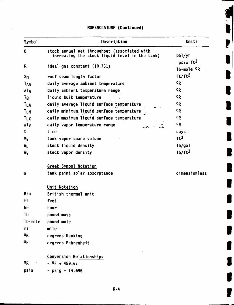
NOMENCLATURE (Continued)
P Symbol Desc r ip t i on Un i t s
Q
R
SD TAA ATA TB TLA TLN TLX ATV
VV WL WV
t
Q
Btu ft h r l b 1 b-mol e m i OR
O F
OR
ps ia
stock annual net throughput (associated w i t h increas ing the stock l i q u i d l e v e l i n the tank)
idea l gas constant (10.731)
r o o f seam leng th f a c t o r d a i l y average ambient temperature d a i l y ambient temperature .range 1 i q u i d bu lk temperature d a i l y average 1 i q u i d surface temperature d a i l y minimum. 1 i-quid .surface temperature d a i l y maximum l i q u i d surface temperature
t ime tank vapor space volume stock l i q u i d dens i ty s tock vapor dens i ty
_. ~ - .~ -. .c -- ~
d a i l y vapor temperature range a,***- -=,
Greek Symbol Nota t ion tank p a i n t so la r absorptance
U n i t Nota t ion B r i t i s h thermal u n i t f e e t hour pound mass pound mole m i l e degrees Rankine degrees Fahrenheit
Conversion Re1 a t ionships O F t 459.67
= p s i g t 14.696
R-4
bb l / y r p s i a f t 3
lb-mole OR
f t / f t 2 OR
OR
OR
OR
OR
OR
OR
days
1 b/gal 1 b / f t 3
f t 3
dimension1 ess
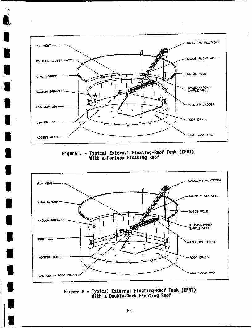
Figure 1 - Typical External Floating-Roof Tank (EFRT) With a Pontoon Floating Roof
GAUGE FLOAT WELL
WIND GlROER
W I D E PDLE
GAUGE-HATCHI SAMPLE U X L
V A C U A BREAKER
Roulffi LAWER
ACCESS HATCH RUCF W A I N
LEG F L O W PAD
Figure 2 - Typical External Floating-Roof Tank (EFRT) With a Double-Deck Floating Roof
F -1

W I M I R I S 1 L FUYllC
R I M VAPOR SPICE
-.NT.GR.Fn *.KLR
N04.L PROOUCT LEVEL FLOITING aw
Figure 3 - llechanical-Shoe Primary Seal With a Rim-Mounted Secondary Seal
Figure 4 - L iqu id -hunted Res i l i en t - F i l l e d (L iqu id -F i l led) Primary Seal With a R im- b u n t e d Secondary Seal
Figure 5 - L iqu id -bunted Res i l ien t - F i l l e d (Foam-Filled) Primary Seal With a Rim- h u n t e d Secondary Seal L
T l N I ScELL"
R I M B A M
PRI*.R"
FLOITING am S E A L I N G LlOUlD
- M I L P R m U T LEVEL BOTTOI DECK
ADAPTALLE Y A L -1
Figure 6 - Vapor-Mounted Res i l ien t - F i 11 ed (Foam-Fi 1 led) Primary Seal With A Rim- Mounted Secondary Seal
F-2
I I I I I I b I 1 I 1

HANDLE -\ BOLTED COVER
GASKET
LlOUlD LEVEL
FLOATING
WELL
ROOF
Figure 7 - Access Hatch
CORD 4
Figure 9 - 6auge-Hatch/Sample Well
CABLE pT
RIM VENT PIPE
PRIMARY.SEAL FABRIC
PRIMARY.SEAL SHOE
FLOATING.RWF RIM
RIM VAPOR SPACE
LIOUID SURFACE
Figure 8 - R i m Vent
-7 ALTERNATIVE PINHOLE
PIN 4 ADJUSTABLE LEG
~~
Figure 11 - Gauge-Float Well
F-3
Figure 10 - Vacuum Breaker

-7 ALTERNATIVE PINHOLE
SLEEVE
FLOATING ROOF
ADJUSTABLE LEG
Figure 12 - Roof L e g
4 7 UNSLOTrED GUIDE POLE
Figure 14 - Unslotted Guide-Pole Ye1 1
SCREENED COVER
OVERFLOW ROOF DRAIN
Figure 13 - Overflow Roof Drain
4 SLOlTED GUIDE POLE
SLIDING C O V E R 1
FLOATING ROOF
LIQUID LEVEL
Figure 15 - Slotted Guide-Pole/Sample Ye1 1 I
E I:
F-4
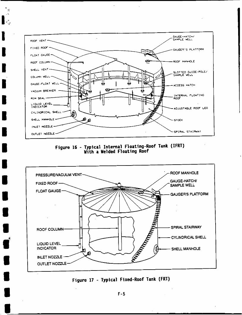
B
GnUGE-MATCH/ SAMPLE WELL
GAUGER'S PLATFORM
ROOF HbWOLE ROOF COLUMN
SLOTTED GUIDE-POLE/ SAMPLE WELL COLUMN YELL
GWGE-FLOAT WELL
VACUUM BREAKER
ACCESS HATCH
INTERNAL FLOATING ROOF
ADJUSTABLE ROOF LEG CYLINDRICAL WELL
SHELL MAN*OLE STOCK
LNLET NQZZLE
OUTLET NOZZLE SPIRAL S T A I R V A Y
Figure 16 - Typical Internal Floating-Roof Tank (IFRT) With a Welded Floating Roof
PRESSURENACUUM VENT ROOF MANHOLE
GAUGE-HATCH/ SAMPLE WELL
GAUGERS PLATFORM
ROOF COLUMN SPIRAL STAIRWAY
CYLINDRICAL SHELL
SHELL MANHOLE LIQUID LEVEL INDICATOR
INLET NOZZLE
OUTLET NOZZLE
Figure 17 - Typical Fixed-Roof Tank (FRT)
F-5
8

Pressure-Vacuum Vent 7 I- - Unsaturated I Vapor
MINIMUM VAPOR SPACE TEMPERATURE
Y Ambient Heating
0
MAXIMUM VAPOR SPACE TEMPERATUFIECOND~ON
Figure 18 - Dai ly h b i e n t Heating-Related Breathing Loss Uechaniw on a FRT
AIR FLOW DOWN INTO THE VAPOR SPACE PAST THE SEAL 7
AIR AND HYDROCARBON FLOW W FROM VAPOR SPACE PAST THE SEAL
Figure 19 - blind-Related Convection Loss Mechanism on an EFRT blith a Vapor-bunted Res i l ien t -F i l l ed Seal
F-6
I I I 1 1 I I I 1 I
I I 1
I I
1
I
i
i
,


Figure 23 - Photograph o f the Pilot lank Test Facility
Outlot Concont r a t i o n 7
P - Prossura T - Tomporatura F - Flaw s - somplo
Figure 24 - Schematic Diagram o f the Pilot lank lest Facility
F-8
L' u I I 1 I

.m ‘J
m I
I 8 4 I
I I I I I I a U I I U
m .- . I
Figure 25 - Photograph o f the Wind Tunnel Test F a c i l i t y
Figure 26 - Schematic Diagram of the Wind Tunnel Test F a c i l i t y
F-9

Figure 27 - Photograph o f the Stock Clingage Test Facility 1
Figure 28 - Schematic Diagram o f the Stock Clingage Test Facility
F-10

4: I' I I I I I I I I I I I I 1 I I m m
1W PRIMARY ONLY
50
- PRIMARVAND SHOE- MOUNTED SECONDARY f
e 10 & v u s E 0 PRIMARYAND RIM-
v) v)
MOUNTED SECONDARY
9 i l w v)
e 0.5 - AVERAGE.FIHINO S E N
TIGHT.FmING S E N
0. I 1 5 10 2030
PRIMARVAhD WEATUER Sr(lEL0 e_ lo-
PRIMARVAND RIM. MOUNTED SECONDARV
- AVERAGE.FIHlNG S E N
TIGHT-FIHING S E N
---
WIND SPEED. V (mYhr) WIND SPEED, V Imwnfl
Figure 29- EFRT R i m Seal Loss Factor, Figure 30- EFRT R i m Seal Loss Factor, FR, Versus Wind Speed For a Welded Tank With a L iqu id- Mounted Resi 1 i e n t - F i l l ed Seal
FR, Versus Wind Speed For a Welded Tank With a Mechanical -Shoe Seal
P R I W ONLY 500
WEATHER SHEW - PRIMARVAND RIM- L MOUNTED SECONDARV
i 100 P R I W ONLY e .* 50 d E i?
3 : 5
WElTHERSHlELD
PRIMARVAND RIM. MOUNTED SECONDARV
0
In
2 10 5 VI
AVEK~GE.FIHING
PRIMARVONLY
PRIMAWAND SHOE. MWNTEDSECONDARV
UOUNTEDSECONDARY PRIMARVAND RIM.
I
- AVERAGE-FIHING S E N
1 5 10 2 0 - N
WIND SPEED. V (minr] 1 5 10 r n m
WIND SPEED, V (rmhr)
Figure 31- EFRT R i m Seal Loss Factor, Figure 32- EFRT R i m Seal Loss Factor, FR. Versus Wind Speed For a Welded Tank With a Vapor- Mounted Resi 1 i e n t - F i 11 ed Seal
FR, Versus Wind Speed For a Riveted Tank With A Mechanical-Shoe Seal
F-11

1 .I
0.f
0.f
0.4
0.2
0
(STOCK DAILY AVERAGE VAPOR PRESSURE) X (VAPOR SPACE OUTAGE). P,H,, (pounds per square inch absolute) x (feet)
Figure 33 - Vented Vapor Saturation Factor, Ks (dimensionless)
STOCKTURNOVER RATE, N (turnovers per year)
Figure 34 - Yorking Loss Turnover Factor, KN (dimensionless)
F-12

I (J
q i I I 1 I I I I I I
TANK TYPE AND SEAL TYPE
Table 1 - EFRT R i m Seal Loss Factor, FR (lb-mole/ft Y r ) . For Average-Fitt ing Seals
5 10
I I I I
13.4 5.52 1.00
~~ I WIND SPEED, V (mi/hr)
37.9 12.7 2.00
5.50 3.41 1.33
WELDED TANK 1. Mechanical-Shoe Seal
a. Primary Only b. Shoe-Mounted Secondary c. Rim-Mounted Secondary
a. Primary Only b. Weather Shield c. Rim-Mounted Secondary
a. Primary Only b. Weather Shield c. Rim-Mounted Secondary
2. Liquid-Mounted Resi l i e n t - F i l l e d Seal
3. Vapor-Mounted Res i l i en t -F i l l ed Seal
11.0 6.35 1.76
RIVETED TANKS 4. Mechanical -Shoe Seal
a. Primary Only b. Shoe-Mounted Secondary c. Rim-Mounted Secondary
48.6 31.0 13.1
239. 143. 79.6
14.5 9.66 2.63
41.1 22.2 7.96
Table 2 - IFRT R i m Seal Loss Factor, FR ( l b - m l e / f t yr), For Average-Fitt ing Seals
TANK TYPE AND SEAL TYPE
WELDED TANK 1. Mechanical -Shoe Seal
a. Primary Only b. Rim-Mounted Secondary
2. Liquid-Mounted Res i l i en t -F i l l ed Seal a. Primary Only b. Rim-Mounted Secondary
3. Vapor-Mounted Res i l i en t -F i l l ed Seal a. Primary Only b. Rim-Mounted Secondary
4. Flexible-Wiper Seal a. Pr imary Only b. Rim-Mounted Secondary
15
69.7 20.6 3.00
16.5 9.15. 2.07
608. 340. 228.
75.5 36.1 15.2
F (1 b-mol e 7 f t y r )
3.0 1.6
3.0 1.6
6.7 2.5
6.7 2.5
T - 1

Table 3 - EFRT Roof F i t t i n g Loss Factor, FF (lb-mole/yr). For Typical Construction Deta i l s
ROOF FITTING TYPE AND CONTRUCTION DETAILS
1.
2.
3.
4.
5.
6.
7.
8.
9.
ACCESS HATCH
R I M VENT Bolted Cover, Gasketed
Weighted Actuation, Gasketed
Weighted Actuation, Gasketed
Weighted Actuation, Gas keted
Adjustable, Pontoon Area
Unbolted Cover, Ungasketed
Open
S l i d ing Cover, Ungasketed
S l i d ing Cover, Ungasketed
GAUGE-HATCH/SAMPLE WELL
VACUUM BREAKER
ROOF LEG
GAUGE-FLOAT WELL
OVERFLOW ROOF DRAIN
UNSLOTTED GUIDE-POLE WELL
SLOTTED GUIDE-POLE/SAMPLE WELL
WIND SPEED, V (mi/hr) I 5
0
1.21
1.65
2.05
2.50
31.8
66.6
324
2,140
~
10
0
1.71
2.35
2.90
3.50
61.3
176
640
4,910
Table 4 - IFRT Roof F i t t i n g Loss Factor, FF (lb-mole/yr), For Typical Construction Deta i l s
ROOF FITTING TYPE AND CONTRUCTION DETAILS
1.
2. 3.
4.
5.
6..
7.
8.
9.
VACUUM BREAKER
STUB DRAIN ACCESS HATCH
ROOF LEG
GAUGELFLOAT WELL
COLUMN WELL
Weighted Actuation, Gasketed
Bolted Cover, Gasketed
Adjustable
Unbolted Cover, Ungasketed
Pipe Column, S1 id ing Cover, Ungasketed
S1 i d i n g Cover, Ungasketed
S1 i d i n g Cover, Ungasketed
S1 i d i n g Cover, Ungasketed
UNSLOTTED GUIDE-POLE WELL
SLOTTED GUIDE - POLE/SAMPLE WELL
LADDER WELL
T-2
3.75
4.50
90.8
7,990
F (1 b-mofe/yr)
0.7 1.2
1.6
7.9
28.0
32.0
32.0
57.0
76.0

i a
i I I 1
PAINT PAINT SHADE COLOR OR TYPE
Aluminum Specular Aluminum D i f f u s e Gray L igh t Gray Med i um Red Primer White - - - - -
I I I I I I I I
I I
m
PAINT CONDITION
Good Poor
0.39 0.49 0.60 0.68 0.54 0.63 0.68 0.74 0.89 0.91 0.17 0.34
Table 5 - Clingage Fac or, C (bb1/1000 ft ?i )
IGunite Lined
0.15
0.15 0.60
PROOUCT STORE0
Gasol i ne Single-Component
Stocks Crude O i l
I SHELL CONDITION I L igh t Dense Rust Rust
0.0015 0.0075
0.0015 0.0075 -t 0.0060 0.030
Table 7 - Assumed Condit ions for Float ing-Roof Tank Sample Problem
CONDITION TYPE
PRODUCT CONDITIONS Type True Vapor Pressure Vapor Molecular Weiqht - L iqu id Densi ty
AVERAGE AMBIENT CONDITIONS Wind Speed Temperature Barometric Pressure
TANK CONOITIONS Tank Types Tank Construct ion 0 i ame t ers Shel l Working Height
EFRT Seal F i t Shell Inner Surface Condit ion F loa t i ng Roof Construct ion and Type F loa t i ng Roof F i t t i n g Types
Sea l F i t Columns and Inner Shel l Surface Condit ion F1 oat i ng Roof Construction F loa t i ng Roof F i t t i n g Types
IFRT F i x e d Roof Type
OPERATING CONDITIONS Throughput
ASSUMED VALUE
Crude O i l 1.5 ps ia 50 1 b / l b-mole 7.1 l b /ga l
10 mi/hr 6OoF 14.7 ps ia
EFRT , I FRT Welded 50, 100, 150, 200 ft. 50 ft.
Average F i t L igh t Rust Welded Double-Deck Typical
Column Supported Average F i t L igh t Rust Welded, Bol ted Typical
10 turnovers/yr
T-3

Table 8 - Evaporative Loss (lb/yr) f o r Each Floating-Roof Tank Loss Source Component
LOSS SOURCE COMPONENT
EXTERNAL FLOATING-ROOF TANK (EFRT)
A. R i m Seal Loss 1. Mechanical-Shoe Seal
a. Primary Only b. Rim-Mounted Secondary
2. Liquid-Mounted Resi 1 ien t -F i 11 ed Seal a. Primary Only b. Rim-Mounted Secondary
3. Vapor-Mounted Res i l i en t -F i l l ed Seal a. Primary Only b. Rim-Mounted Secondary
6 . Roof F i t t i n g Loss
C. Roof Seam Loss
D. Withdrawal Loss
INTERNAL FLOATING-ROOF TANK ( I F R T )
A. R i m Seal Loss 1. Liquid-Mounted R e s i l i e n t - F i l l e d Seal
o r Mechanical -Shoe Sea l a. Pr imary Only b. Rim-Younted Secondary
o r Flexible-Wiper Seal a. Primary Only b. Rim-Mounted Secondary
2. Vapor-Mounted Res i l i en t -F i l l ed Seal
8. Roof F i t t i n g Loss 1. Welded F loat ing Roof 2. Bolted F loat ing Roof
C. Roof Seam loss I 1. Welded F loat ino Roof 2. Bolted F loat ing Roof
D. Withdrawal Loss
50
1,021 54
206
6,4- 2,142
383
0
141
P1
180 67
161 174
0 91
143
TANK DIAMETER, ( f t )
100
2,042 108
592 95
12,882 4,284
519
0
281
161 86
360 135
354 406
0 366
298
- 150
3,062 161
888 142
9,323 6,426
655
0
422
-
242 129
54 1 202
651 767
0 023
447
200
4,083 215
1,184 189
25,764 8,567
791
0
562
323 172
721 269
1,051 1,257
0 1,463
624

<
I,? 1 I I I I I I I I I I I I I I I I I
:
20,399 7,502
Table 9 - Total Evaporative Loss (lb/yr) for Floating-Roof Tank Sample Problem
27,117 9,921
TANK DESCRIPTION
1,340 1,227
EXTERNAL FLOATING-ROOF TANK (EFRT)
1,997 1,047
A. Welded Floating Roof 1. Mechanical -Shoe Seal
a. Primary Only b. Rim-Mounted Secondary
2. Liquid-Mounted Resilient-Filled Seal a. Primary Only b. Rim-Mounted Secondary
3. Vapor-Mounted Resi 1 i ent -Fi 1 1 ed Seal a. Primary Only b. Rim-Mounted Secondary
INTERNAL FLOATING-ROOF TANK (IFRT)
A. Welded Floating Roof 1. Liquid-Mounted Resilient-Filled Seal
or Mechanical-Shoe Seal a. Primary Only b. Rim-Mounted Secondary
2. Vapor-Mounted Resi 1 i ent -Fi 1 1 ed Seal or Flexible-Wiper Seal a. Primary Only b. Rim-Mounted Secondary
B. Bolted Floating Roof 1. Liauid-Mounted Resilient-Filled Seal
or 'Mechanical -Shoe Seal a. Primary Only b. Rim-Mounted Secondary
or Flexible-Wiper Seal a. Primary Only b. Rim-Mounted Secondary
2. Vapor-Mounted Resilient-Filled Seal
T-5
50
1,545 578
820 571
6,965 2,666
385 348
485 372
490 452
509 476
TANK DIAMETER, (ft)
100
2,842 908
1,392 895
13,682 5,084
814 738
1,013 707
1,231 1,156
1,430 1,204 21570 2,239 I 3,613 49065