7400 series ups single module and 1+1 configuration · pdf file4.8 cable top entry kit ... the...
TRANSCRIPT
Manual Reference: 6310018A - 2 (02/98) LCA 10/01
7400 Series UPSSingle Module
and1+1 Configuration
User Manual
MEASUREMENTS ALARM INVERTER EMERGENCY
Vo
f
Io
B (( ))
OFF
ON
MEASUREMENTS ALARMINVERTER
EMERGENCY
Vo
f
Io
B (( ))
OFF
ON
MEASUREMENTS ALARMINVERTER
EMERGENCY
Vo
f
Io
B (( ))
OFF
ON
MEASUREMENTS ALARMINVERTER
EMERGENCY
Vo
f
Io
B (( ))
OFF
ON


7400 Series UPSSingle and 1+1 IOM Manual 6310018a.02.doc
Prelim iIssue 2(02/98)
IMPORTANTThis manual contains information concerning the installation, operation and maintenance of the
Liebert Series 7400 Uninterruptible Power System (UPS) for the Single Module and One plusOne Systems.
All relevant parts of the manual should be read prior to commencing installation.
The UPS must be commissioned by an engineer approved by the manufacturer (or hisagent) before being put into to service. Failure to observe this condition will invalidate any
implied warranty.
The Series 7400 UPS has been designed for Commercial/Industrial use only.
The Series 7400 UPS has not been designed for direct use in any life support applications.
If you encounter any problems with the procedures contained in this manual you should seekimmediate assistance from the Liebert Sales Office from whom the equipment was purchased.Alternatively contact the manufacturer's Customer Support department at the address shown
below:
Customer Service and Support Department,Customer Support Systems,
Liebert EuropeGlobe Park, Marlow, SL7 1YG, U.K.
Telephone (01628) 403200Fax (01628) 403302
Outside the UK prefix the number with - (44 - 1628)
The manufacturer reserves the right to change the equipment design without notice.
©Copyright 1998 by Liebert Europe.Unauthorised reproduction prohibited

7400 Series UPS6310018a.02.doc Single and 1+1 IOM Manual
Prelim iiIssue 2 (02/98)
All rights reserved.

7400 Series UPSSingle and 1+1 IOM Manual 6310018a.02.doc
Prelim iiiIssue 2(02/98)
ELECTRO MAGNETIC COMPATIBILITY
WARNINGThis is a UPS for restricted sales distribution to informed partners with the appropriate
EMC technical competence. Installation restrictions or additional measures may be neededto prevent disturbances (EMC Standard 50091-2).
To convert to a class `A' UPS, the following factory installedoptional e.m.c. kits must be fitted:
80 kVA Module - Option kit part number 4641018 S
120 kVA Module - Option kit part number 4641014 O
200 kVA Module - Option kit part number 4641029 D
300 kVA Module - Option kit part number -
400 kVA Module - Option kit part number -
When fitted with the above optional e.m.c. kits the following warning applies:This is a class `A' UPS product. In a domestic environment this product
may cause radio interference in which case the user may berequired to take additional measures.
This equipment complies with the requirements of the EMC Directive 89/336/EECand the published technical standards.
Continued compliance requires installation in accordance with these instructionsand the use of manufacturer approved accessories only.
7400 Series UPS6310018a.02.doc Single and 1+1 IOM Manual
Prelim ivIssue 2 (02/98)
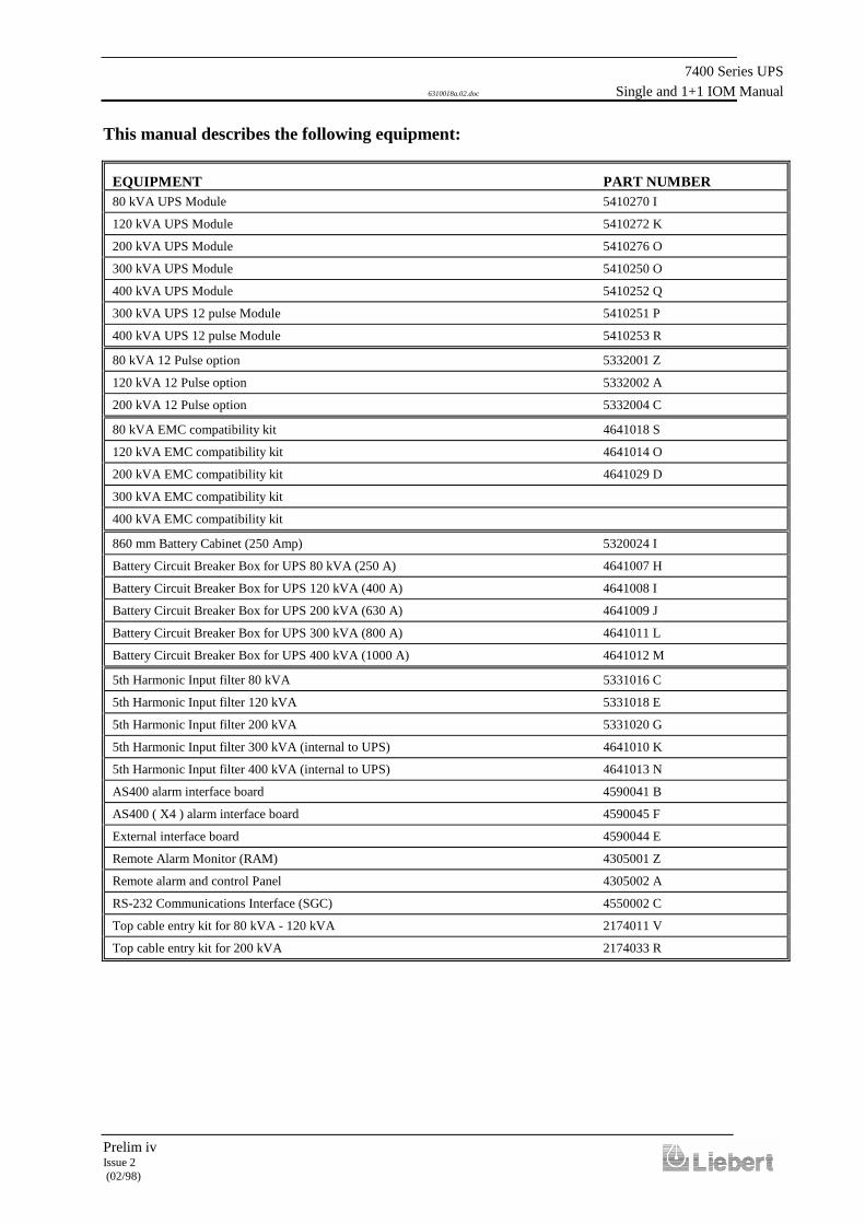
This manual describes the following equipment:
EQUIPMENT PART NUMBER80 kVA UPS Module 5410270 I
120 kVA UPS Module 5410272 K
200 kVA UPS Module 5410276 O
300 kVA UPS Module 5410250 O
400 kVA UPS Module 5410252 Q
300 kVA UPS 12 pulse Module 5410251 P
400 kVA UPS 12 pulse Module 5410253 R
80 kVA 12 Pulse option 5332001 Z
120 kVA 12 Pulse option 5332002 A
200 kVA 12 Pulse option 5332004 C
80 kVA EMC compatibility kit 4641018 S
120 kVA EMC compatibility kit 4641014 O
200 kVA EMC compatibility kit 4641029 D
300 kVA EMC compatibility kit
400 kVA EMC compatibility kit
860 mm Battery Cabinet (250 Amp) 5320024 I
Battery Circuit Breaker Box for UPS 80 kVA (250 A) 4641007 H
Battery Circuit Breaker Box for UPS 120 kVA (400 A) 4641008 I
Battery Circuit Breaker Box for UPS 200 kVA (630 A) 4641009 J
Battery Circuit Breaker Box for UPS 300 kVA (800 A) 4641011 L
Battery Circuit Breaker Box for UPS 400 kVA (1000 A) 4641012 M
5th Harmonic Input filter 80 kVA 5331016 C
5th Harmonic Input filter 120 kVA 5331018 E
5th Harmonic Input filter 200 kVA 5331020 G
5th Harmonic Input filter 300 kVA (internal to UPS) 4641010 K
5th Harmonic Input filter 400 kVA (internal to UPS) 4641013 N
AS400 alarm interface board 4590041 B
AS400 ( X4 ) alarm interface board 4590045 F
External interface board 4590044 E
Remote Alarm Monitor (RAM) 4305001 Z
Remote alarm and control Panel 4305002 A
RS-232 Communications Interface (SGC) 4550002 C
Top cable entry kit for 80 kVA - 120 kVA 2174011 V
Top cable entry kit for 200 kVA 2174033 R

7400 Series UPSSingle and 1+1 IOM Manual 6310018a.02.doc
Prelim vIssue 2(02/98)
Safety Precautions
WARNING
THIS UPS DOES NOT INCORPORATE AUTOMATIC BACKFEED PROTECTION. AWARNING LABEL MUST BE FITTED TO ALL EXTERNAL PRIMARY POWER
ISOLATORS STATING:ISOLATE THE UNINTERRUPTIBLE POWER SYSTEM BEFORE WORKING ON THIS
CIRCUIT.
General
In common with other types of high power equipment, dangerous voltages are present within the UPSand battery enclosure. The risk of contact with these voltages is minimised as the live component parts
are housed behind a hinged, lockable door. Further internal safety screens make the equipmentprotected to IP20 standards. No risk exists to any personnel when operating the equipment in the
normal manner, following the recommended operating procedures.All equipment maintenance and servicing procedures involve internal access and should be carried out
only by trained personnel.
Batteries
Battery manufacturers supply details of the necessary precautions to be observed whenworking on, or in the vicinity of, a large bank of battery cells. These precautions should be
followed implicitly at all times.Particular attention should be paid to the recommendations concerning local environmental
conditions and the provision of protective clothing, first aid and fire-fighting facilities.
Test Equipment
When the battery is under charge it is earth-referenced about its mid-point e.g. if the batteryis being charged at 446 V the battery extremities will be at +223V and -223V with respect toneutral (earth). When using mains-powered test equipment such as oscilloscopes in the UPS
high voltage area, always use a differential mode of operation to avoid the need todisconnect the oscilloscope frame earth.
Personnel
When working inside the UPS (trained personnel only) it is recommended that protection beworn to prevent eye damage, should an electrical arc be struck by mishandling or severe
electrical fault.Some of the power components are very heavy. If their removal is necessary ensure that
sufficient manpower is available, otherwise use adequate mechanical handlingequipment.When working in the general area of the UPS where high voltages are present, a
second person should be standing-by to assist and summon help in case of accident.

7400 Series UPS6310018a.02.doc Single and 1+1 IOM Manual
Prelim viIssue 2 (02/98)
Table of Contents
1. Chapter 1 - General Description.............................................................................................................................1-11.1 Introduction ..........................................................................................................................................................1-11.2 Design Concept ....................................................................................................................................................1-1
1.2.1 Module Design ..............................................................................................................................................1-11.2.2 Bypass supplies .............................................................................................................................................1-51.2.3 UPS Power Switch Configuration ..............................................................................................................1-51.2.4 Battery circuit breaker ...................................................................................................................................1-61.2.5 Battery Cabinet ..............................................................................................................................................1-61.2.6 Battery circuit breaker box ............................................................................................................................1-6
1.3 One Plus One System ...........................................................................................................................................1-81.3.1 Redundant vs Non-Redundant configuration................................................................................................1-81.3.2 One-Plus-One Parallel Control ......................................................................................................................1-81.3.3 Common battery ..........................................................................................................................................1-10
1.4 Operator Control Panel.......................................................................................................................................1-121.4.1 Mimic indications ........................................................................................................................................1-121.4.2 Control switches ..........................................................................................................................................1-131.4.3 LCD Display................................................................................................................................................1-15
2. Chapter 2 - Operating Instructions..........................................................................................................................2-12.1 Introduction ..........................................................................................................................................................2-1
2.1.1 General notes .................................................................................................................................................2-12.2 One plus One ........................................................................................................................................................2-1
2.2.1 Redundant module system .............................................................................................................................2-12.2.2 Non-Redundant module system.....................................................................................................................2-3
3. Chapter 3 - Installation Procedure ..........................................................................................................................3-13.1 Introduction ..........................................................................................................................................................3-1
3.1.1 Equipment positioning and environmental considerations ...........................................................................3-23.1.2 Raised floor installation.................................................................................................................................3-33.1.3 Battery Location ............................................................................................................................................3-3
3.2 Preliminary Checks.............................................................................................................................................3-133.3 Reassembling the 300 kVA and 400 kVA cabinets ............................................................................................3-143.4 Connecting the UPS power cables......................................................................................................................3-16
3.4.1 Cable entry...................................................................................................................................................3-163.4.2 Cable rating .................................................................................................................................................3-163.4.3 Cable connections........................................................................................................................................3-173.4.4 Safety earth..................................................................................................................................................3-173.4.5 Cabling procedure .......................................................................................................................................3-18
3.5 Battery Installation .............................................................................................................................................3-243.5.1 860 mm cabinet (250 Amp circuit breaker) .................................................................................................3-253.5.2 Battery circuit breaker boxes .......................................................................................................................3-283.5.3 Battery Display Initialisation .......................................................................................................................3-31
4. Chapter 4 - Optional equipment .............................................................................................................................4-14.1 AS400 Interface Board (4590041B).....................................................................................................................4-2
4.1.1 AS400 Interface Board outputs .....................................................................................................................4-24.1.2 Remote control inputs....................................................................................................................................4-24.1.3 Calibration .....................................................................................................................................................4-2
4.2 4-Way AS400 Interface Board (4590045F) .........................................................................................................4-44.2.1 Remote control inputs....................................................................................................................................4-44.2.2 Calibration .....................................................................................................................................................4-4
4.3 Output Interface (Remote Alarms) Boards (4590044E) .......................................................................................4-64.3.1 Alarm outputs ................................................................................................................................................4-64.3.2 Remote control inputs....................................................................................................................................4-6
4.4 Remote Alarm Monitor (RAM) (P/N 4305001Z).................................................................................................4-8

7400 Series UPSSingle and 1+1 IOM Manual 6310018a.02.doc
Prelim viiIssue 2(02/98)
4.4.1 Connections ...................................................................................................................................................4-84.5 Remote Alarm and Control Panel (Part No. 4305002 A) ...................................................................................4-10
4.5.1 Introduction .................................................................................................................................................4-104.5.2 Connections .................................................................................................................................................4-11
4.6 RS 232 Communications Management Board (SGC) (4550002C) ....................................................................4-154.6.1 Introduction .................................................................................................................................................4-154.6.2 General Information ....................................................................................................................................4-16
4.7 5th Harmonic Input Filter ...................................................................................................................................4-184.7.1 Introduction .................................................................................................................................................4-184.7.2 Specification................................................................................................................................................4-184.7.3 Notes on connection ....................................................................................................................................4-18
4.8 Cable top entry kit ..............................................................................................................................................4-244.8.1 Introduction .................................................................................................................................................4-24
4.9 Pulse Option .......................................................................................................................................................4-254.9.1 Introduction .................................................................................................................................................4-254.9.2 Electrical connection ...................................................................................................................................4-25
4.10 Option Board Kit (Part no. 77000005) .............................................................................................................4-294.10.1 Introduction ...............................................................................................................................................4-294.10.2 Installation .................................................................................................................................................4-29
5. Chapter 5 - Maintenance.........................................................................................................................................5-15.1 Introduction ..........................................................................................................................................................5-15.2 Safety Precautions ................................................................................................................................................5-15.3 Scheduled Maintenance........................................................................................................................................5-1
5.3.1 Daily checks ..................................................................................................................................................5-15.3.2 Weekly checks...............................................................................................................................................5-35.3.3 Annual Service ..............................................................................................................................................5-35.3.4 Extended service............................................................................................................................................5-45.3.5 Battery maintenance ......................................................................................................................................5-4
6. Chapter 6 - Troubleshooting...................................................................................................................................6-16.1 Troubleshooting UPS Systems .............................................................................................................................6-1
6.1.1 Operating parameters and limitations ............................................................................................................6-16.1.2 General Troubleshooting Procedure .............................................................................................................6-1
6.2 Display panel message interpretation ...................................................................................................................6-5
7. Chapter 7 - SPECIFICATION................................................................................................................................7-1


7400 Series UPS User Manual Chapter 1 - General DescriptionSingle Module and One plus One Systems Introduction
6310018a.02.doc
1-1Issue 2
(02/98)
1. Chapter 1 - General Description
1.1 Introduction
The 7400 Series uninterruptible power supply (UPS) system is connectedbetween a critical load, such as a computer, and its three phase mainspower supply. Being designed to furnish a well regulated 3 phase outputpower supply under all rated load and input supply conditions, thesystem offers the user the following advantages:-Increased power quality:The UPS has its own internal voltage and frequency regulator circuitswhich ensure that its output is maintained within close tolerancesindependent of voltage and frequency variations on the mains powerlines.Increased noise rejection:By rectifying the input a.c. power to d.c. power, and then converting itback to a.c., any electrical noise present on the input mains supply line iseffectively isolated from the UPS output, therefore the critical load seesonly clean power.Power blackout protection:If the mains power fails, the UPS continues to power the critical loadfrom its battery source, leaving the load immune from powerdisturbances.
1.2 Design Concept
This section describes an individual module’s operating principles forboth 6 and 12 pulse systems - the effects of the additional parallel controlfacilities required on the one plus one system on the standard module aredescribed later.
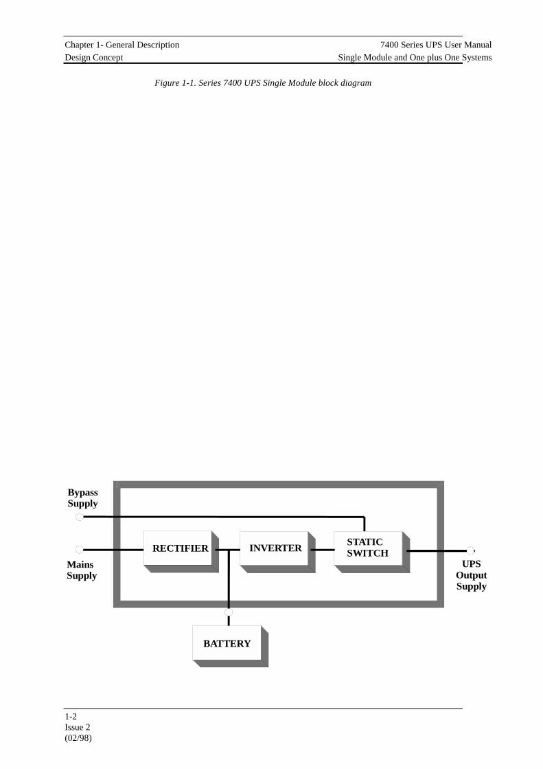
6 pulse RectifierThe UPS basically operates as an AC-DC-AC converter (see figure 1-1).The first conversion stage (from a.c. to d.c.) uses a 3 phase, fully-controlled SCR bridge rectifier to convert the incoming mains supplyinto a regulated 446 V d.c. busbar for a 400 V a.c. input (or 432 V d.c.for a 380 V a.c. input or 459 Vd.c. for a 415V a.c. input).
1.2.1 Module Design
Chapter 1- General Description 7400 Series UPS User ManualDesign Concept Single Module and One plus One Systems
1-2Issue 2(02/98)
Figure 1-1. Series 7400 UPS Single Module block diagram
Mains Supply
RECTIFIER STATICSWITCH
BATTERY
INVERTERUPS
OutputSupply
BypassSupply

7400 Series UPS User Manual Chapter 1 - General DescriptionSingle Module and One plus One Systems Introduction
1-3Issue 2(02/98)
12 Pulse RectifierThe UPS basically operates as an a.c.-d.c.-a.c. converter (see figure 1-1).The first conversion stage (from a.c. to d.c.) uses a 3 phase 12 pulse (2 x6 pulse), fully-controlled SCR bridge rectifier system to convert theincoming mains supply into a regulated d.c. busbar (432V d.c. for a380V a.c. input; 446V d.c. for a 400V a.c. input or 459V d.c. for a 415Va.c. input).The input a.c. supply is applied (a) directly into a six pulse rectifier and(b) via a 30° phase shift transformer into a second six pulse rectifier (seefigure 1-2). This phase shifting results in less distortion of the alternating
input supply (i.e. the lower order harmonics are cancelled).
InverterThe d.c. busbar produced by the rectifier provides both battery chargingpower and power to the inverter section-which uses the latest IGBTswitched pulse width modulation (PWM) design and provides the secondconversion phase; i.e. reconverting the d.c. busbar voltage back into ana.c. voltage waveform.During normal operation both the rectifier and inverter sections areactive and provide regulated load power whilst simultaneously floatcharging the battery. In the event of a mains power failure, the rectifierbecomes inoperative and the inverter is powered solely from the battery.Critical load power is maintained under these conditions until the batteryis fully discharged, whereupon the UPS shuts down. The end of batterydischarge is assumed when the battery voltage falls to 320 Vd.c. for asystem with a 380V a.c. input supply, 330V d.c. with a 400V a.c. inputsupply and 340V d.c. with a 415V a.c. input supply.The period for which the load can be maintained following a mainspower failure is known as the system’s ‘Autonomy Time’ and isdependent upon both the battery A/Hr capacity and the appliedpercentage load. It is usual in larger installations to provide analternative UPS input power source from a standby generator when the
L1
L2
AT1
Mains Supply
12 Pulse(2 x 6 pulse)Rectifier system
To DCBusbar
DCInductor
Phasedisplacementtransformer
Inductor Rectifierbridges
Rectifierbridges
Figure 1-2 . 12 Pulse rectifier block diagram

Chapter 1- General Description 7400 Series UPS User ManualDesign Concept Single Module and One plus One Systems
6310018a.02.doc
1-4Issue 2(02/98)
mains supply fails. Once such a generator has been brought on-line, andthe UPS input power has been re-established, the batteries
7400 Series UPS User Manual Chapter 1 - General DescriptionSingle Module and One plus One Systems Design Concept
6310018a.02.doc
1-5Issue 2(02/98)
immediately begin to recharge. Modern generators can be started andbrought on-line very quickly and where such a facility is incorporatedinto the UPS installation it results in short battery discharge periods andcorrespondingly rapid recharge times.
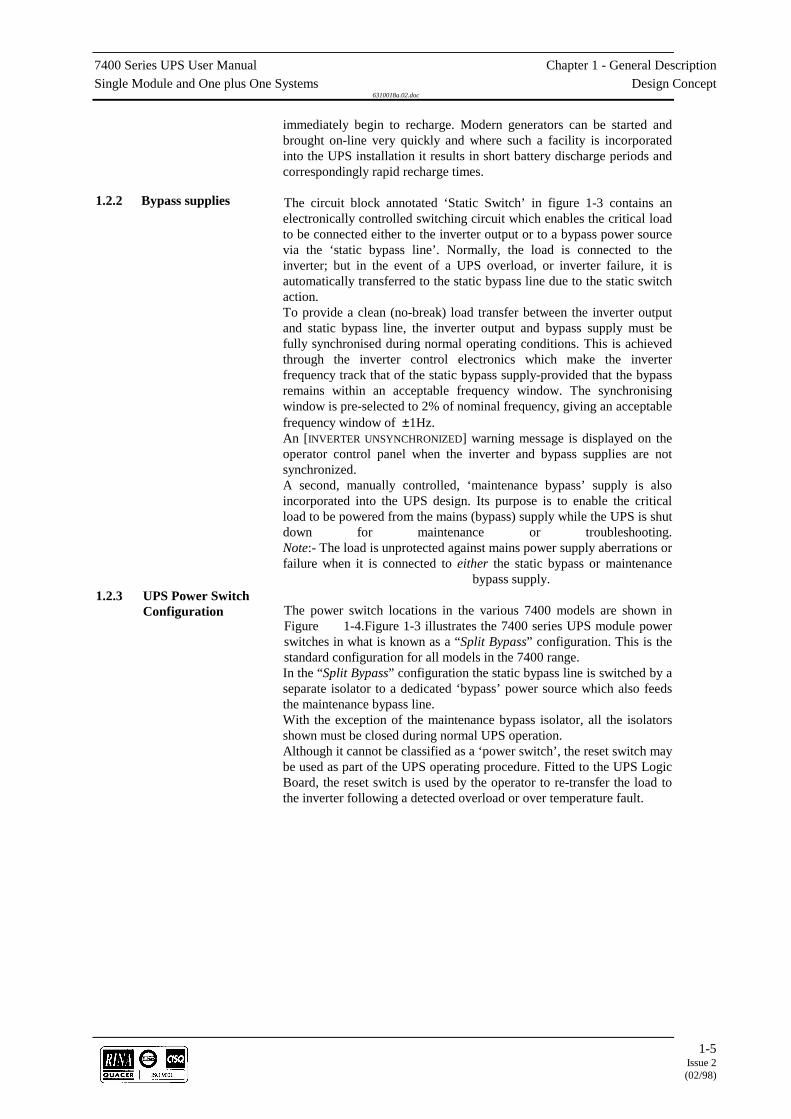
The circuit block annotated ‘Static Switch’ in figure 1-3 contains anelectronically controlled switching circuit which enables the critical loadto be connected either to the inverter output or to a bypass power sourcevia the ‘static bypass line’. Normally, the load is connected to theinverter; but in the event of a UPS overload, or inverter failure, it isautomatically transferred to the static bypass line due to the static switchaction.To provide a clean (no-break) load transfer between the inverter outputand static bypass line, the inverter output and bypass supply must befully synchronised during normal operating conditions. This is achievedthrough the inverter control electronics which make the inverterfrequency track that of the static bypass supply-provided that the bypassremains within an acceptable frequency window. The synchronisingwindow is pre-selected to 2% of nominal frequency, giving an acceptablefrequency window of ±1Hz.An [INVERTER UNSYNCHRONIZED] warning message is displayed on theoperator control panel when the inverter and bypass supplies are notsynchronized.A second, manually controlled, ‘maintenance bypass’ supply is alsoincorporated into the UPS design. Its purpose is to enable the criticalload to be powered from the mains (bypass) supply while the UPS is shutdown for maintenance or troubleshooting.Note:- The load is unprotected against mains power supply aberrations orfailure when it is connected to either the static bypass or maintenance
bypass supply.
The power switch locations in the various 7400 models are shown inFigure 1-4.Figure 1-3 illustrates the 7400 series UPS module powerswitches in what is known as a “Split Bypass” configuration. This is thestandard configuration for all models in the 7400 range.In the “Split Bypass” configuration the static bypass line is switched by aseparate isolator to a dedicated ‘bypass’ power source which also feedsthe maintenance bypass line.With the exception of the maintenance bypass isolator, all the isolatorsshown must be closed during normal UPS operation.Although it cannot be classified as a ‘power switch’, the reset switch maybe used as part of the UPS operating procedure. Fitted to the UPS LogicBoard, the reset switch is used by the operator to re-transfer the load tothe inverter following a detected overload or over temperature fault.
1.2.2 Bypass supplies
1.2.3 UPS Power SwitchConfiguration

Chapter 1- General Description 7400 Series UPS User ManualDesign Concept Single Module and One plus One Systems
6310018a.02.doc
1-6Issue 2(02/98)
Figure 1-1 . Series 7400 UPS isolator configuration
The battery is connected to the d.c. Busbar through a circuit breakerfitted inside the battery cabinet or located adjacent to the batteries wherea battery cabinet is not used. This circuit breaker is closed manually, butit contains an undervoltage release coil which enables it to be trippedfrom the UPS control electronics following certain detected faults. It alsohas a magnetic trip facility for overload protection.
In the case of the 80kVA and 120kVA UPS models, the batteriesassociated with the UPS are generally housed in a purpose-built cabinetlocated along-side the main UPS equipment.It is possible to install batteries of various types and capacity in thecabinet to obtain the required autonomy characteristics.The battery cabinet can be purchased in one of the following forms:1. Complete installation comprising the battery cabinet, batteries and
circuit breaker.2. Battery cabinet and circuit breaker only with no batteries.3. Battery cabinet only with no batteries or circuit breaker.
For the larger units and as an alternative to the battery cabinets, abattery circuit breaker can be provided in a custom built box. ThisBattery Circuit Breaker Box is designed to be wall or rack mounted andis connected between the UPS and Battery.
MainsSupply
RECTIFIER STATICSWITCH
BATTERY
INVERTER
UPSOutputSupply
Bypass Supply
BatteryCircuitBreaker
InputIsolator
OutputIsolator
Bypass Isolator
MaintenanceBypass Isolator
1.2.4 Battery circuit breaker
1.2.5 Battery Cabinet
1.2.6 Battery circuit breakerbox

7400 Series UPS User Manual Chapter 1 - General DescriptionSingle Module and One plus One Systems Design Concept
6310018a.02.doc
1-7Issue 2(02/98)
200 kVA120 kVA
300-400 kVA80 kVA
I4 I3 I2 I1
I4 I1
I3
I2
I1 = Input IsolatorI2 = Static Bypass IsolatorI3 = Maintenance Bypass Isolator (with padlock)I4 = Output Isolator
I4 I3 I2 I1 I4 I3 I2 I1
Figure 1-1 . Power isolator identification
Chapter 1- General Description 7400 Series UPS User ManualOne Plus One System Single Module and One plus One Systems
6310018a.02.doc
1-8Issue 2(02/98)
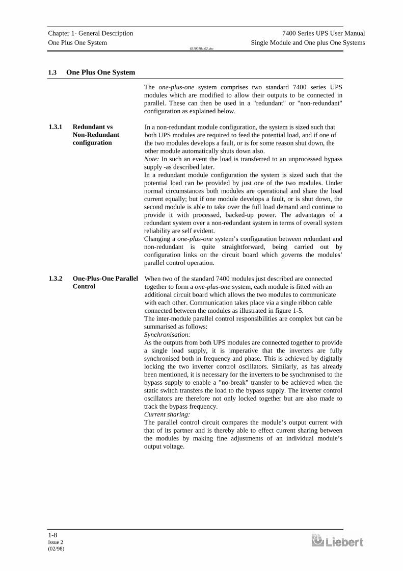
1.3 One Plus One System
The one-plus-one system comprises two standard 7400 series UPSmodules which are modified to allow their outputs to be connected inparallel. These can then be used in a "redundant" or "non-redundant"configuration as explained below.
In a non-redundant module configuration, the system is sized such thatboth UPS modules are required to feed the potential load, and if one ofthe two modules develops a fault, or is for some reason shut down, theother module automatically shuts down also.Note: In such an event the load is transferred to an unprocessed bypasssupply -as described later.In a redundant module configuration the system is sized such that thepotential load can be provided by just one of the two modules. Undernormal circumstances both modules are operational and share the loadcurrent equally; but if one module develops a fault, or is shut down, thesecond module is able to take over the full load demand and continue toprovide it with processed, backed-up power. The advantages of aredundant system over a non-redundant system in terms of overall systemreliability are self evident.Changing a one-plus-one system’s configuration between redundant andnon-redundant is quite straightforward, being carried out byconfiguration links on the circuit board which governs the modules’parallel control operation.
When two of the standard 7400 modules just described are connectedtogether to form a one-plus-one system, each module is fitted with anadditional circuit board which allows the two modules to communicatewith each other. Communication takes place via a single ribbon cableconnected between the modules as illustrated in figure 1-5.The inter-module parallel control responsibilities are complex but can besummarised as follows:Synchronisation:As the outputs from both UPS modules are connected together to providea single load supply, it is imperative that the inverters are fullysynchronised both in frequency and phase. This is achieved by digitallylocking the two inverter control oscillators. Similarly, as has alreadybeen mentioned, it is necessary for the inverters to be synchronised to thebypass supply to enable a "no-break" transfer to be achieved when thestatic switch transfers the load to the bypass supply. The inverter controloscillators are therefore not only locked together but are also made totrack the bypass frequency.Current sharing:The parallel control circuit compares the module’s output current withthat of its partner and is thereby able to effect current sharing betweenthe modules by making fine adjustments of an individual module’soutput voltage.
1.3.1 Redundant vsNon-Redundantconfiguration
1.3.2 One-Plus-One ParallelControl

7400 Series UPS User Manual Chapter 1 - General DescriptionSingle Module and One plus One Systems One Plus One System
6310018a.02.doc
1-9Issue 2(02/98)
Redundancy configuration:A link in the parallel control logic determines whether the one-plus-onesystem operates in a "redundant" or "non-redundant" configuration.If a non-redundant mode is selected the two static switch sections areeffectively locked together in that both static switches are turned off oron by a single control signal. Thus if one module develops a fault, whenrunning, its static switch control logic will transfer its output from theinverter to the static bypass line and simultaneously send a signal to thestatic switch control logic in the second module to do likewise.This does not happen if the system is configured as a redundant system,in which case the second module is allowed to continue supplying theload from its inverter when the first module trips its inverter off line.Reverse current:A reverse current monitor circuit detects current flowing into, rather thanout of, the module’s output terminals. Such a condition can arise if amodule develops an internal power fault or if for some reason the twomodules become unbalanced, and is liable to further damage the moduleand also degrade the load supply. If a reverse current is detected theinverter on the affected module is immediately shut down and(depending on the system redundancy configuration) the load istransferred to the bypass supply "Non-Redundant system", or remains onthe good inverter "Redundant system".
Chapter 1- General Description 7400 Series UPS User ManualOne plus One System Single Module and One plus One Systems
6310018a.02.doc
1-10Issue 2(02/98)
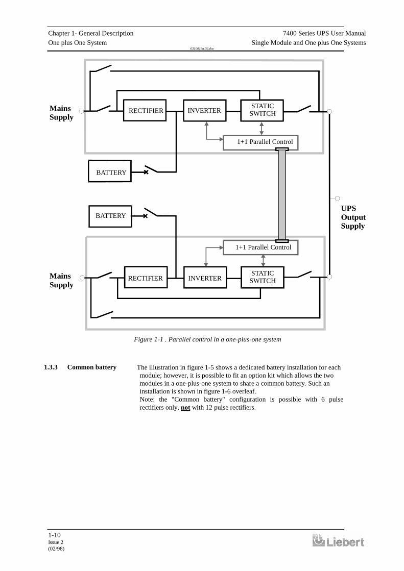
The illustration in figure 1-5 shows a dedicated battery installation for eachmodule; however, it is possible to fit an option kit which allows the twomodules in a one-plus-one system to share a common battery. Such aninstallation is shown in figure 1-6 overleaf.Note: the "Common battery" configuration is possible with 6 pulserectifiers only, not with 12 pulse rectifiers.
1+1 Parallel Control
MainsSupply
MainsSupply
RECTIFIERSTATIC
SWITCH
BATTERY
INVERTER
UPSOutputSupply
1+1 Parallel Control
RECTIFIERSTATIC
SWITCH
BATTERY
INVERTER
Figure 1-1 . Parallel control in a one-plus-one system
1.3.3 Common battery
7400 Series UPS User Manual Chapter 1 - General DescriptionSingle Module and One plus One Systems One Plus One System
6310018a.02.doc
1-11Issue 2(02/98)
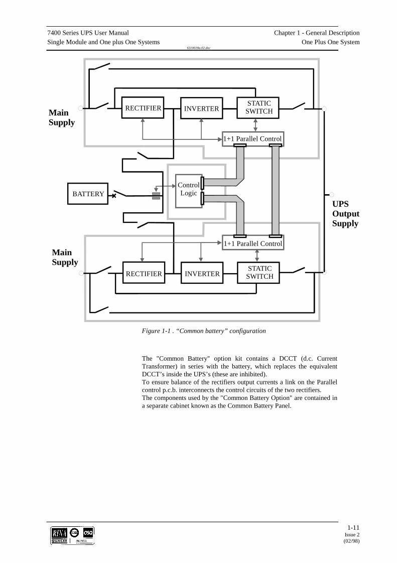
The "Common Battery" option kit contains a DCCT (d.c. CurrentTransformer) in series with the battery, which replaces the equivalentDCCT’s inside the UPS’s (these are inhibited).To ensure balance of the rectifiers output currents a link on the Parallelcontrol p.c.b. interconnects the control circuits of the two rectifiers.The components used by the "Common Battery Option" are contained ina separate cabinet known as the Common Battery Panel.
BATTERY
1+1 Parallel Control
RECTIFIER INVERTERSTATIC
SWITCH
Control Logic
MainSupply
MainSupply
UPSOutputSupply
RECTIFIER INVERTERSTATIC
SWITCH
1+1 Parallel Control
Figure 1-1 . “Common battery” configuration

Chapter 1- General Description 7400 Series UPS User ManualOperator Control Panel Single Module and One plus One Systems
6310018a.02.doc
1-12Issue 2(02/98)
1.4 Operator Control Panel
The operator control panel is divided into three functional areas; ‘mimicindications’, ‘control switches’, and ‘LCD display panel’.
Six leds are mounted on a single line diagram to represent the variousUPS power paths. These leds, which
are annotated in figure 1-8, show the current UPS operational status andshould be interpreted as detailed below.LS1 - Input supply OK / Rectifier operative:This led illuminates when theinput isolator (I1) is closed, theinput supply is within 20% ofnominal voltage, and therectifier is operative.LS2 - Battery volts OK: Thisled illuminates when thebattery circuit breaker is closedand the battery voltage iswithin the UPS operating range(320V - 490V nominal).LS3 - bypass supply OK: Thisled illuminates when the staticbypass supply is within ±10%of its nominal voltage.LS4 - Inverter output OK:This led illuminates when theinverter is operating and its output is within a preset (±10%) acceptablevoltage window.LS5 - Load on bypassThis led illuminates when the output isolator is closed and the load isconnected to the bypass supply via the static switch.LS6 - Load on inverter:This led illuminates when the output isolator is closed and the load isconnected to the inverter via the static switch.
Figure 1-1 . Operator control panel
1.4.1 Mimic indications
LS3
LS5
LS1 LS2 LS4 LS6
Figure 1-1 . Mimic panel

7400 Series UPS User Manual Chapter 1 - General DescriptionSingle Module and One plus One Systems Operator Control Panel
6310018a.02.doc
1-13Issue 2(02/98)
Seven tactile switches are located on the Operator Panel, together withan emergency stop pushbutton which is fitted with a safety cover toprevent inadvertent operation.
Switch S1 (Vo) - Output volts:When this switch is pressed, the lower line of the LCD Display showsthe output line-to-line voltages on all three phases.Switch S2 (Fo) - Output frequency:When this switch is pressed, the lower line of the LCD Display showsthe output frequency.Switch S3 (Io) - Output current:When this switch is pressed, the lower line of the LCD Display showsthe output line (and neutral) currents.Switch S4 (B) - Battery:When this switch is pressed, the lower line of the LCD Display showsthe battery voltage, current and % charge or autonomy time remaining inminutes. Note that a discharging current is symbolised by a precedingminus [ ] sign.Switch S5 - ((.)) - Alarm reset:Pressing this switch cancels the audible alarm. The alarm led andmessages will remain active if a detected fault condition is still present.Switch S6 - Inverter OFF:Pressing this switch turns OFF the inverter and causes the load to betransferred to the static bypass supply.Switch S7 - Inverter ON:Pressing this switch activates the inverter and causes the load to betransferred to the inverter side of the static switch after the invertervoltage has had time to stabilise.Switch S8 - Emergency stop:When the emergency stop switch is pressed it disables the static switchblock entirely (so removing load power). It also disables the rectifier andinverter, and trips the battery circuit breaker. Under normalcircumstances it does not remove UPS input power since this is appliedthrough a manually controlled isolator; however, if the UPS input supplyis connected via a circuit breaker having an electrical trip facility theemergency stop signal can be used to drive the external circuit breaker’strip circuit.There are two leds contained within the switch panel area:LS7 - Alarm:This led accompanies the audible alarm warning when any alarmcondition is initiated. The audible warning can be cancelled by the resetswitch (S5) but LS7 will only extinguish after the alarmed condition hasreverted to normal.
1.4.2 Control switches
S1
S2 S3 S4 LS7 S5 S6 S7 LS8 S8
Figure 1-1 . Control panel switches

Chapter 1- General Description 7400 Series UPS User ManualOperator Control Panel Single Module and One plus One Systems
6310018a.02.doc
1-14Issue 2(02/98)
LS8 - Inverter status:This green led situated near the inverter ON switch illuminates when theinverter is selected ON.

7400 Series UPS User Manual Chapter 1 - General DescriptionSingle Module and One plus One Systems Operator Control Panel
6310018a.02.doc
1-15Issue 2(02/98)
An LCD display, capable ofshowing two rows of 40characters, is used to indicatethe UPS operatingparameters, warnings andalarms.A DIP switch fitted to thedisplay microprocessor boardenables the displayed languageto be easily selected to English,French, Italian, Spanish orGerman.The lower row of charactersare used to display meteredparameters; which includeoutput (or bypass) voltage,frequency, or current togetherwith battery current, voltageand % charge or timeremaining on battery.Warning and alarm messagesare displayed on the upper rowof characters. The ALARM ledand audible warningaccompany all alarm messagesbut are not activated bywarning messages. In all cases,the message automaticallyresets when the alarmed (orwarning) condition reverts tonormal.
When two (or more) alarm orwarning conditions are activesimultaneously, theappropriate messages aredisplayed in a cyclic fashion,with each message appearing on the display for approximately 10 seconds.
Battery condition displayYou can display the relative condition/state of the battery as a % of thenominal capacity with the input a.c. power supply present by pressingswitch 4 (‘B’) . The time remaining on battery is automatically displayedin minutes during a input ac power supply failure.On first installation or on the installation of a new battery the nominalcapacity of the battery must be entered into the system software (seechapter 3).
1.4.3 LCD Display*** ALARM ***
*** ALARM ***
*** ALARM ***
*** ALARM ***
*** ALARM ***
*** ALARM ***
*** ALARM ***
*** ALARM ***
EMERGENCY STOP
INVERTER OFF OR FAILED
OVER TEMPERATURE
OVERLOAD
BATTERY CB OPEN
OUTPUT CB OPEN
INPUT CB OPEN
RECTIFIER OFF OR FAILED
** WARNING *
** WARNING *
** WARNING *
** WARNING *
** WARNING *
UPS ON MAINTENANCE BYPASS
INVERTER UNSYNCHRONIZED
BATTERY ON LOAD
MAINS FAILURE
LOAD ON BYPASS
Figure 1-1 .Display messages


7400 Series UPS User Manual Chapter 2 - Operating InstructionsSingle Module and One plus One Systems Introduction
6310018a.02.doc
2-1Issue 2(02/98)
2. Chapter 2 - Operating Instructions
2.1 Introduction
The UPS can be considered to be in one of three operating conditions:
• Shutdown - All power isolators and circuit breakers open - noload power.
• On Maintenance Bypass - UPS shut down but the load connectedto the unprotected mains via the Maintenance Bypass Supply line.
• Normal operation - All relevant power isolators and circuitbreakers closed, the load is powered by the UPS.
This chapter contains detailed instructions to enable you to switchbetween these three conditions.
Note 1: All the user controls and indicators mentioned in theseprocedures are identified in chapter 1 (figures 1-3, 1-4, 1-7, 1-8 and 1-9).Note 2: The audible alarm may annunciate at various points in theseprocedures. It can be cancelled at any time by pressing the `Alarm Reset'pushbutton.Note 3: The 7400 series UPS incorporates an optional automatic boostcharge facility which can be used in systems containing non-sealed lead-acid batteries. If this type of battery is used in your installation you maynotice that the battery charger voltage will be greater than its normalvalue when the mains supply returns from a prolonged outage. Therevised voltage will be 460V d.c. for a 380V a.c. system, 475V d.c. for a400V a.c. system and 490V d.c. for a 415V a.c system. This is thenormal response of the boost charge facility: the charger voltage shouldreturn to normal after a few hours.
2.2 One plus One
Starting and stopping the one-plus-one system is the same as a singlemodule, however the modules' response depends on whether it isconfigured as a Redundant or Non-Redundant system. The operatingprocedures are the same irrespective of the selected redundancy mode; insimple terms you start (stop) one module and then repeat the operationon the second module.
The difference in the system response concerns the point at which theload is transferred between the bypass and uninterruptible (i.e. inverter)supplies and is summarised below:
Starting:When starting a redundant module system the load is transferred fromthe bypass to the inverter of the first module as soon as the first moduleis started and its inverter is brought on line. When the second module isstarted its static bypass line is totally inhibited due to the first modulebeing on line, and the second module will not be connected to the loaduntil its inverter is operational and fully synchronised with the firstmodule.
Stopping:
2.1.1 General notes
2.2.1 Redundant modulesystem

When the first module is stopped its static bypass is inhibited because theload will be fully maintained by the inverter of the second module.

Chapter 2 - Operating Instructions 7400 Series UPS User ManualOne plus One Single Module and One plus One Systems
6310018a.02.doc
2-3Issue 2(02/98)
When shutting down the second module, the static bypass lines of bothmodules will be turned on as soon as its inverter is stopped. That is, bothmodules will provide load power through their paralleled bypass lines.
Starting:In a Non-Redundant module system both modules must be runningbefore the load is transferred to their paralleled inverters. Therefore,when the first module is started, the load will remain connected to itsstatic bypass line while waiting for the second module to synchronise.
Stopping:The load will be transferred to the static bypass lines in both modulessimultaneously as soon as the inverter stops in the first module to be shutdown.
How to turn on the system from a shutdown condition
This procedure should be followed when turning on the UPS from a fully powered down condition - i.e. where the load is notbeing initially supplied through the internal Maintenance Bypass supply.Note: For a one plus one system, complete these actions on one module at a time.
Step Action Response1. Close the module's Output Isolator and check that the UPS
input mains supply (and bypass supply if separate) isturned on externally.
2. Close the Input Isolator and Static Bypass Isolator . Mimic panel ledsLS1 LS3 and LS5 should illuminate immediately, toindicate that the load is being supplied through the staticbypass line. (NB: In a one plus one Redundant Modulesystem LS5 will not illuminate on the second module tobe started as its static bypass line is inhibited).
The inverter should start automatically once the d.c.Busbar reaches its working voltage (after about 30seconds), and when this occurs LS4 (inverter OK) willilluminate followed by LS6 (load on inverter). (NB: In aone plus one Non-Redundant module system LS6 will notilluminate on the first module to be started until youreach this point in starting the second module.)
Note that LS5 will extinguish when LS6 illuminates.
3. Wait 20 seconds then close the battery circuit breaker: Thisis located inside the battery cabinet (if used) or isotherwise located adjacent to the battery racks
Mimic panel ledsLS2 should illuminate on the mimic panel and LS7(alarm) should extinguish.
4. Press the battery metering selector switch [B]: The display should indicate a positive (+) batterycharging current.
2.2.2 Non-Redundantmodule system

Chapter 2 - Operating Instructions 7400 Series UPS User ManualOne plus One Single Module and One plus One Systems
6310018a.02.doc
2-4Issue 2(02/98)
How to turn on the system from a maintenance power-down condition
This procedure should be followed to start the UPS from a MAINTENANCE power-down condition - i.e. where the load isbeing initially powered through the internal maintenance bypass supply.Note: For a one plus one system, complete these actions on one module at a time.
Step Action Response1. Check that the UPS input mains supply (and bypass supply
if separate) is turned on externally.2. Close the Input Isolator and Static Bypass Isolator. Mimic panel leds
LS1 and LS3 should illuminate immediately, to indicatethat the input and bypass supplies are healthy.
The inverter should start automatically once the d.c.Busbar reaches its working voltage (after about 30seconds), and when this occurs LS4 (inverter OK) willilluminate
3. Wait 20 seconds then close the battery circuit breaker: Thisis located inside the battery cabinet (if used) or otherwiseadjacent to the battery racks.
Mimic panel ledsLS2 should illuminate.
4. Press the battery metering selector switch [B]: The display should indicate a positive (+) batterycharging current.
5. Press the Inverter OFF pushbutton (S6).( On both modules for a 1 + 1 system ).
Mimic panel ledsLS4 should extinguish.
6. Close the Output Isolator.( On both modules for a 1 + 1 system ).
Mimic panel ledsLS5 should illuminate to indicate that the load isconnected to the static bypass line. (On both modules fora 1 + 1 system).
7. Open the Maintenance Bypass Isolator (on both modulesin a one plus one system) then Press the Inverter ONswitch (S7) (on both modules in the one plus one system).(NB: The inverters of both modules are inhibited if eithermodules' Maintenance Bypass Isolator is closed.)
Mimic panel ledsLS4 (Inverter OK) and LS6 (Load on inverter) shouldilluminate after approximately 30 seconds. (NB: In a oneplus one Non-Redundant module system LS6 will notilluminate on the first module to be started until youreach this point in starting the second module.).
LS5 should extinguish at the same time as LS6illuminates.LS7 (alarm) should extinguish.
7400 Series UPS User Manual Chapter 2 - Operating InstructionsSingle Module and One plus One Systems One plus One
6310018a.02.doc
2-5Issue 2(02/98)
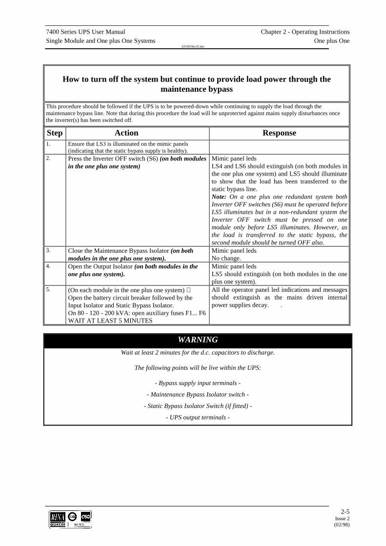
How to turn off the system but continue to provide load power through themaintenance bypass
This procedure should be followed if the UPS is to be powered-down while continuing to supply the load through themaintenance bypass line. Note that during this procedure the load will be unprotected against mains supply disturbances oncethe inverter(s) has been switched off.
Step Action Response1. Ensure that LS3 is illuminated on the mimic panels
(indicating that the static bypass supply is healthy).2. Press the Inverter OFF switch (S6) (on both modules
in the one plus one system)Mimic panel ledsLS4 and LS6 should extinguish (on both modules inthe one plus one system) and LS5 should illuminateto show that the load has been transferred to thestatic bypass line.Note: On a one plus one redundant system bothInverter OFF switches (S6) must be operated beforeLS5 illuminates but in a non-redundant system theInverter OFF switch must be pressed on onemodule only before LS5 illuminates. However, asthe load is transferred to the static bypass, thesecond module should be turned OFF also.
3. Close the Maintenance Bypass Isolator (on bothmodules in the one plus one system).
Mimic panel ledsNo change.
4. Open the Output Isolator (on both modules in theone plus one system).
Mimic panel ledsLS5 should extinguish (on both modules in the oneplus one system).
5. (On each module in the one plus one system) Open the battery circuit breaker followed by theInput Isolator and Static Bypass Isolator.On 80 - 120 - 200 kVA: open auxiliary fuses F1... F6WAIT AT LEAST 5 MINUTES
All the operator panel led indications and messagesshould extinguish as the mains driven internalpower supplies decay. .
WARNINGWait at least 2 minutes for the d.c. capacitors to discharge.
The following points will be live within the UPS:
- Bypass supply input terminals -
- Maintenance Bypass Isolator switch -
- Static Bypass Isolator Switch (if fitted) -
- UPS output terminals -

Chapter 2 - Operating Instructions 7400 Series UPS User ManualOne plus One Single Module and One plus One Systems
6310018a.02.doc
2-6Issue 2(02/98)
How to totally power-down the system
This procedure should be followed only if the UPS AND LOAD are to be completely powered down.
Step Action Response1. Press the Inverter OFF switch (S6) (on both modules
in the one plus one system):Mimic panel ledsLS4 and LS6 should extinguish, and LS5 shouldilluminate to show that the load has been transferredto the static bypass line. (NB: in a Non-RedundantModule system LS5 and LS6 will also change-overon the second module).
2. Open the battery circuit breaker: Mimic panel ledsLS2 should extinguish.
3. Open the Input Isolator and Static Bypass Isolator.On 80 - 120 - 200 kVA open auxiliary fuses F1 ... F6
All the operator panel led indications and messagesshould extinguish as the mains driven internalpower supplies decay.
IMPORTANTThe Maintenance Bypass Isolator may be operated at any timewhen the UPS is powered down to connect/disconnect the load
to the raw maintenance bypass supply if required.
Emergency stopThe emergency stop pushbutton is located behind a hinged safety shield to prevent
inadvertent operation. When this switch is pressed modules are electronically shut down andbattery circuit breakers are tripped. Power is removed from the critical load,
but pressing the emergency stop pushbutton will not remove the modules' input mainssupply unless an external contactor, controlled via the emergency stop pushbutton auxiliaries,
is fitted in the mains supply line..

7400 Series UPS User Manual Chapter 2 - Operating InstructionsSingle Module and One plus One Systems One plus One
6310018a.02.doc
2-7Issue 2(02/98)


7400 Series UPS User Manual Chapter 3 - Installation ProcedureSingle Module and One plus One Systems Introduction
6310018a.02.doc
3-1Issue 2
(02/98) LCA 10/01
3. Chapter 3 - Installation Procedure
3.1 Introduction
WARNINGDo not apply electrical power to the UPS equipment before the arrival of the
commissioning engineer.
WARNINGThe UPS equipment should be installed by a qualified engineer in accordance with the
information contained in this chapter and the drawing package shipped inside theUPS cabinet.
WARNING
Battery hazardsSpecial care should be taken when working with the batteries associated with thisequipment. When connected together, the battery terminal voltage will exceed 400
Vd.c. and is potentially lethal.
Eye protection should be worn to prevent injury from accidental electrical arcs.Removerings , watches and all metal objects.Only use tools with insulated handles.
Wear rubber gloves.
If a battery leaks electrolyte, or is otherwise physically damaged,it should be placed in a container resistant to sulphuric acid and
disposed of in accordance with local regulations.
If electrolyte comes into contact with the skin the affected areashould be washed immediately.
This chapter contains information regarding the positioning and cablingof the UPS equipment and batteries.Because every site has its peculiarities, it is not the aim of this chapter toprovide step-by-step installation instructions, but to act as a guide as tothe general procedures and practices that should be observed by theinstalling engineer.
Chapter 3 - Installation Procedure 7400 Series UPS User ManualIntroduction Single Module and One plus One Systems
6310018a.02.doc
3-2Issue 2(02/98)
The UPS cabinets can be moved by fork lift or crane. Fork lift aperturesare provided in the sides of the base plate and are accessible afterremoving blanking covers fitted to the side panel ventilation grills. Roof-mounted eye-bolts are fitted to enable the cabinet to be crane-handled.These can be removed once the equipment has been finally positioned.Note: In a 1 + 1 system the models should be positioned adjacent to each
other.
WARNINGEnsure that the UPS weight is within the designated S.W.L. of any handling equipment.
See the UPS specification for weight details.
Do not move the battery cabinet with the batteries fitted..
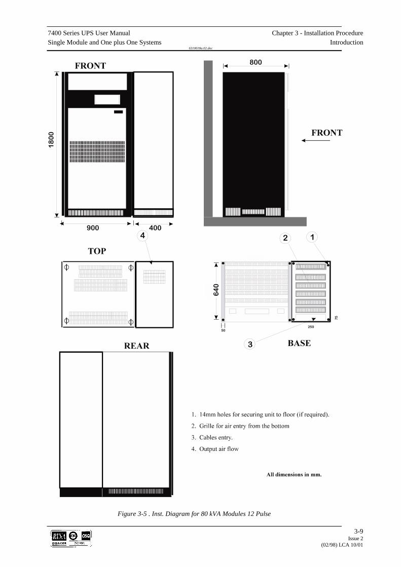
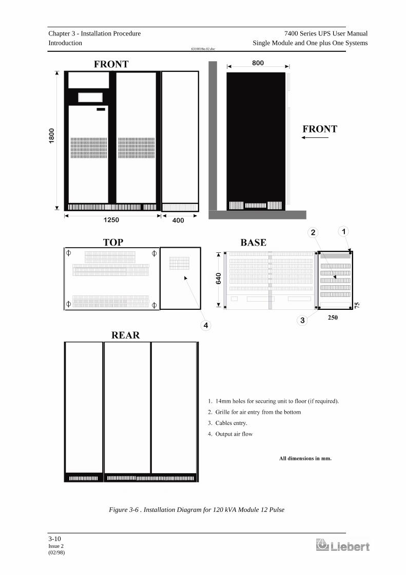
The 300kVA and 400 kVA UPS modules are split into two cabinets, aMain Inverter cabinet and a Rectifier/Static Bypass cabinet, to alloweasier transportation and positioning. Once finally positioned, the twocabinets have to be bolted together and the interlinking power andcontrol cable connections made. It is therefore necessary to observecabinet A & B positioning (see figures 3-5 and 3-6 ).The UPS module should be located in a cool, dry, clean-air environmentwith adequate ventilation to keep the ambient temperature within thespecified operating range. If necessary, a system of extractor fans shouldbe installed to aid cooling-air flow, and a suitable air filtration systemused where the UPS is to operate in a dirty environment.
CablesAll control cables whether screened or not, should be run, separate fromthe power cables, in metal conduits or metal ducts which are electricallybonded to the metalwork of the cabinets to which they are connected.
Cooling air flowAll the models in the 7400 range are force-cooled with the aid of internalfans. Cooling air enters the module through ventilation grills located atvarious parts of the cabinet and exhausted through grills located in theequipment roof. When the equipment is located on a raised floor, andbottom cable entry is used, additional cooling air also enters the UPS viathe floor void.
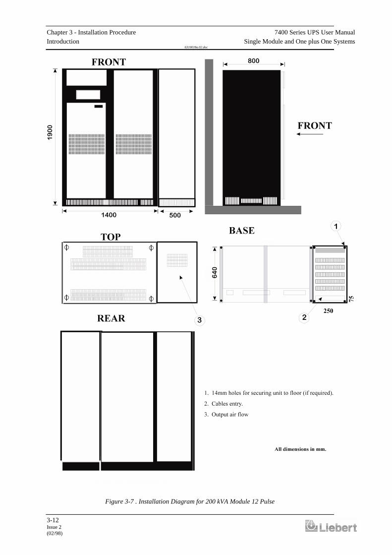
ClearancesTo allow adequate cooling air flow, you should position the equipmentwith the following space around the back and sides.80kVA-120 kVA Models 100mm minimum required in all cases.200/300/400 kVA Models 300mm minimum required in all cases.The UPS modules do not require back-access for maintenance servicing;but, where space permits, a clearance of approximately 4 feet (1.2metres) will ease access to some component parts. Clearance around thefront of the equipment should be sufficient to enable free passage ofpersonnel with the doors fully opened.
3.1.1 Equipment positioningand environmentalconsiderations

7400 Series UPS User Manual Chapter 3 - Installation ProcedureSingle Module and One plus One Systems Introduction
6310018a.02.doc
3-3Issue 2
(02/98) LCA 10/01
If the equipment is to be located on a raised floor it should be mountedon a pedestal suitably designed to accept the equipment point loading.The installation diagrams in the back of this manual identify the locationof the holes in the base plate through which the equipment can be bolted
to the floor.
Note: Temperature is a major factor in determining the battery life andcapacity. Battery manufacturers quote figures for an operatingtemperature of 20°C. Operating above this temperature will reduce thebattery life, operation below this temperature will reduce the batterycapacity. On a normal installation the battery temperature is maintainedbetween 15°C and 25°C.In 80kVA and 120 kVA module installations the batteries associatedwith the UPS equipment are usually contained in a purpose-built batterycabinet which sits alongside the main UPS equipment. Sealed,maintenance-free batteries are normally used in this type of installation.Due to their increased capacity, the batteries associated with larger UPSinstallations are usually too big to be mounted in a single cabinet and areeither rack mounted or fitted in multiple, or bespoke, battery cabinets.Such installations may utilise non-sealed lead acid cells, requiringregular attention and impose their own environmental requirements.Pedestals are required for the battery cabinets when they are located onraised floors, in the same way as for the UPS cabinets.The batteries are connected to the UPS through a circuit breaker which ismanually closed and electronically tripped via the UPS control circuitry.If the batteries are cabinet-mounted this circuit breaker is fitted withinthe cabinet; however, if the batteries are rack-mounted or otherwiselocated remote to the main UPS cabinet then the battery circuit breakermust be mounted as near as possible to the batteries themselves, and thepower and control cables connected to the UPS using the most directroute possible. Liebert offer a purpose-designed remote battery circuitbreaker box, containing the circuit breaker and its necessary controlboard, as a standard option kit.
3.1.2 Raised floorinstallation
3.1.3 Battery Location
Chapter 3 - Installation Procedure 7400 Series UPS User ManualIntroduction Single Module and One plus One Systems
6310018a.02.doc
3-4Issue 2(02/98)
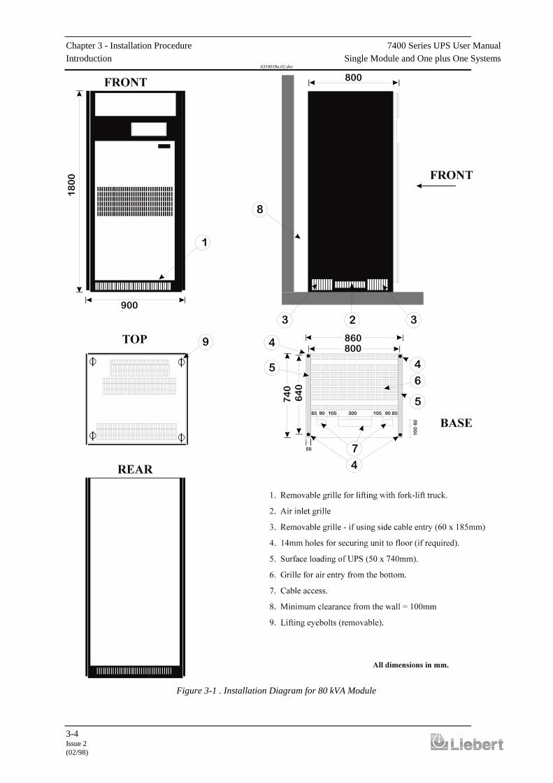
Figure 3-1 . Installation Diagram for 80 kVA Module
7400 Series UPS User Manual Chapter 3 - Installation ProcedureSingle Module and One plus One Systems Introduction
6310018a.02.doc
3-5Issue 2
(02/98) LCA 10/01
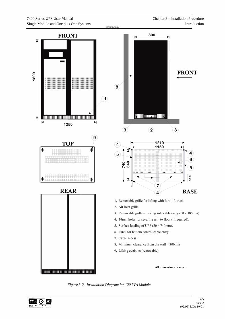
Figure 3-2 . Installation Diagram for 120 kVA Module

Chapter 3 - Installation Procedure 7400 Series UPS User ManualIntroduction Single Module and One plus One Systems
6310018a.02.doc
3-6Issue 2(02/98)
7400 Series UPS User Manual Chapter 3 - Installation ProcedureSingle Module and One plus One Systems Introduction
6310018a.02.doc
3-7Issue 2
(02/98) LCA 10/01
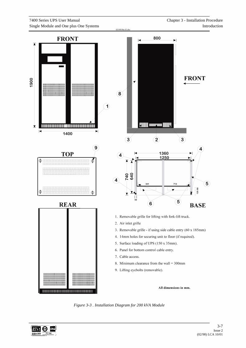
Figure 3-3 . Installation Diagram for 200 kVA Module

Chapter 3 - Installation Procedure 7400 Series UPS User ManualIntroduction Single Module and One plus One Systems
6310018a.02.doc
3-8Issue 2(02/98)
Figure 3-4 . Installation Diagram for 300/400 kVA Module 6 & 12
7400 Series UPS User Manual Chapter 3 - Installation ProcedureSingle Module and One plus One Systems Introduction
6310018a.02.doc
3-9Issue 2
(02/98) LCA 10/01
Figure 3-5 . Inst. Diagram for 80 kVA Modules 12 Pulse
Chapter 3 - Installation Procedure 7400 Series UPS User ManualIntroduction Single Module and One plus One Systems
6310018a.02.doc
3-10Issue 2(02/98)
Figure 3-6 . Installation Diagram for 120 kVA Module 12 Pulse

7400 Series UPS User Manual Chapter 3 - Installation ProcedureSingle Module and One plus One Systems Introduction
6310018a.02.doc
3-11Issue 2
(02/98) LCA 10/01
Chapter 3 - Installation Procedure 7400 Series UPS User ManualIntroduction Single Module and One plus One Systems
6310018a.02.doc
3-12Issue 2(02/98)
Figure 3-7 . Installation Diagram for 200 kVA Module 12 Pulse

7400 Series UPS User Manual Chapter 3 - Installation ProcedureSingle Module and One plus One Systems Preliminary Checks
6310018a.02.doc
3-13Issue 2(02/98)
3.2 Preliminary Checks
Before you install the UPS hardware you should carry out the followingpreliminary checks:
1. Verify that the UPS room satisfies the environmental conditionsstipulated in the equipment specification, paying particular attentionto the ambient temperature and air exchange system.
2. Remove any packaging debris then visually examine the UPS and
battery equipment for transit damage, both internally and externally.Report any such damage to the shipper immediately.
3. Verify that the shipment is complete e.g. that the battery contains
the correct number of cells etc. Report any discrepancy immediately. 4. When you are satisfied that the equipment is complete and in good
condition move it to its proposed final position. Note: If ‘side’ cable entry is to be used (see below) ensure that the
blanking plates are removed before finally fixing the cabinets inposition.
5. All models have a stabilising bar fitted to the output transformer T1
during shipment, this should be removed when the UPS has beenplaced in its final position.
CautionEnsure the stabilising bar fitted to the output transformer T1 is removed before
proceeding with the installation.

Chapter 3 - Installation Procedure 7400 Series UPS User ManualReassembling the 300kVA and 400kVA cabinets Single Module and One plus One Systems
6310018a.02.doc
3-14Issue 2(02/98)
3.3 Reassembling the 300 kVA and 400 kVA cabinets
Place the cabinets in their final position as shown in figure 3-6 ensuringany protective packaging is removed (Inverter Cabinet on the right andRectifier/Static Switch Cabinet on the left), and connect them togetherfollowing the procedure below:
CautionEnsure loose cables are not trapped between the two cabinet frames.
1. Align the Rectifier/Static switch and Inverter Cabinets and bolt themtogether through the holes provided.
2. Open the doors to the Inverter cabinet and remove the lower
protective cover to gain access to the a.c. busbars R, S, T & N fromthe output transformer T1.
3. Locate the four a.c. busbars from the Output Isolator numbered 7(R),
8(S), 9(T) and 10(N) in the Rectifier/Static Switch cabinet and thelinking straps connected to them. Take the free end of the linkingstraps and connect them to the Inverter cabinet a.c. busbars ensuringcorrect phase connection as illustrated in figure 3-6.
4. Ensure the transformer transportation stabilising bar is removed.
Refit the lower protective cover to the Inverter cabinet. 5. Open the upper inner left hand protective door of the inverter cabinet
to gain access to the d.c. busbars. 6. Open the doors to the Rectifier/Static Switch cabinet and open the
inner upper right hand door to gain access to the d.c. busbars. 7. Using the two angled copper busbar links provided, connect the
Rectifier/Static Switch cabinet d.c. busbar to the Inverter Cabinet d.c.busbar as illustrated in figure 3-6.
8. Locate the flat cable assembly FC17 from CN8 on the Inverter Logic
board in the Inverter cabinet and secure to the end panel, in theposition illustrated in figure 3-6.
9. Locate the flat cable assembly FC17 from CN2 on the UPS Logic
board in the Rectifier/Static Switch cabinet and connect to cableassembly FC17 secured above.
10. Locate wires 27, 28, 29, 30, 31, 32, 33, 98 & 99 terminated in
connector CN4 and wires 7, 8, 9 & 10 terminated in connector CN5in the Inverter cabinet and secure the connectors into cabinet endpanel in the positions illustrated in figure 3-6.
11. Locate the Rectifier/Static Switch cabinet cable assemblies from the
Interface board which terminate in connectors CN4 and CN5 andconnect to CN4 and CN5 secured above.
12. Close the inner protective doors and outer doors to both cabinets.

7400 Series UPS User Manual Chapter 3 - Installation ProcedureSingle Module and One plus One Systems Reassembling the 300kVA and 400kVA cabinets
6310018a.02.doc
3-15Issue 2
(02/98) LCA 10/01
Figure 3-1 . 300/400 kVA model inter-connection cables

Chapter 3 - Installation Procedure 7400 Series UPS User ManualBattery Installation Single Module and One plus One Systems
6310018a.02.doc
3-16Issue 2(02/98)
3.4 Connecting the UPS power cables
WARNINGBefore cabling-up the UPS, ensure that you are aware of the location and operation of
the external isolators that connect the UPS input/bypass supply to the mainsdistribution panel.
Check that these supplies are electrically isolated, and post any necessary warning signsto prevent their inadvertent operation.
Cables can enter the smaller UPS modules and battery cabinet eitherfrom below or through either side. Side entry is made possible byremoving blanking pieces fitted in the side ventilation grills to reveal thecable entry holes. This cable entry method allows the equipment to bepositioned on a solid floor without the need for cable trenching and alsoallows cables to pass from one module to the other when positioned side-
by-side.
On units up to 200kVA normal cable entry is from the bottom, however,if top entry is necessary, the optional top entry kit Pt.No. 2174011 Vfor80 and 120kVA or Pt. No. 2174033 R for 200kVA is required. On the300/400kVA unit cable entry is from the bottom or top of the unit.
The maximum current ratings for the power cables are given in table 3-1.The neutral cable (bypass and output) should be sized at up to 1.5 timesthe phase current to take into account the possible presence of 3rdarmonic currents due to single phase "computer loads".
In a one-plus-one Non-Redundant system, the lenght of the cables on theBypass line of the two UPS’s should be equal (+/- 20%) to ensure thebalance of the currents, when the load is supplied by the mains.
UPSRATING
NOMINAL CURRENT (Amps) CABLE CONNECTIONMAXIMUM SIZE
(kVA) Input Mains(with full battery recharge)
380V
Bypass/output380V
Battery(at low battery
disconnect)
Input/outputCable
Terminations
BatteryTermin-
ations6 Pulse 12 Pulse U - V - W - N +ve & -ve
80 167 158 121 216 Secure with M8 Bolt M8 Bolt120 251 237 182 322 Secure with M10 Bolt M10 Bolt200 412 390 304 534 Secure with M10 Bolt M10 Bolt300 609 579 442 791 Secure with M12 Bolt M12 Bolt400 808 769 608 1053 Secure with M12 Bolt M12 Bolt
Table 3-1 - Nominal current for power cables
When sizing battery cables, a maximum volt drop of 3V d.c. ispermissible at the urrent ratings given in table 3-1.
3.4.1 Cable entry
3.4.2 Cable rating

7400 Series UPS User Manual Chapter 3 - Installation ProcedureSingle Module and One plus One Systems Connecting the UPS power cables
6310018a.02.doc
3-17Issue 2
(02/98) LCA 10/01
Power cables are connected either directly to their respective circuitbreakers, or to busbars which are themselves connected to the circuitbreakers see figures 3-8 to 3-12.Note: If the installation includes the use of optional Input Filter Cabinetsrefer immediately to the Options Chapter, Where these cabinets are fullydescribed. The inclusion of these cabinets in the system affects themethod of connecting the UPS power cables given below.
The safety earth busbars are located near the input and output powersupply connections as shown in the
following diagrams. The safety cable must be connected to the earthbusbar bonded to each module cabinet.All cabinets and cable trunking should be earthed in accordance withlocal regulations.
WARNINGFAILURE TO FOLLOW ADEQUATE EARTHING PROCEDURES CAN RESULT IN
ELECTRIC SHOCK HAZARD TO PERSONNEL, OR THE RISK OF FIRE, SHOULD
AN EARTH FAULT OCCUR.
3.4.3 Cable connections
3.4.4 Safety earth

Chapter 3 - Installation Procedure 7400 Series UPS User ManualBattery Installation Single Module and One plus One Systems
6310018a.02.doc
3-18Issue 2(02/98)
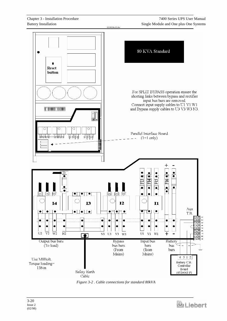
Power CablesOnce the equipment has been finally positioned and secured, connect thepower cables as described in the following procedure.Study the connection diagrams in figures 3-8 to 3-11 and positivelyidentify the diagram relevant to your equipment before commencingcabling.
1. Verify that the UPS equipment is totally isolated from its externalpower source and all the UPS isolators are open.
2. On each module, connect the input supply cables between the mains
distribution panel and the UPS input mains terminals. Check thatlinks are fitted between input mains bus bars and bypass supply busbars (U1 - U3; V1 - V3; W1 - W3).
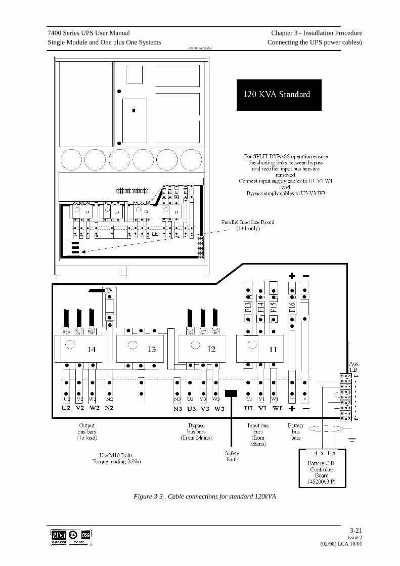
ENSURE CORRECT PHASE ROTATION. 3. If a "split-bypass" configuration is used, connect the UPS bypass
supply cables between the bypass distribution panel and the UPSbypass supply terminals on each module. Ensure any links fittedbetween input and bypass bus bars are removed.
ENSURE CORRECT PHASE ROTATION. 4. On a Single module connect the UPS output cables between the UPS
and the load distribution panel. 5. On modules in a one plus one system connect the output terminals of
both modules together (in parallel). ENSURE CORRECT PHASE-PHASE CONNECTION (U2-U2, V2-
V2, W2-W2, N2-N2). Then connect the UPS output cables between the paralleled UPS output
terminals and load distribution panel. Note: If the UPS is to be commissioned before the load equipment is
ready to receive power then SAFELY isolate the load cables. 6. On each module, connect the battery cables between the UPS battery
terminals and its associated battery circuit breaker see figures 3-13to 3-17. As a safety precaution remove the battery fuse in the moduleuntil the arrival of the commissioning engineer. OBSERVE THE BATTERY CABLE POLARITY.
WARNINGDo not close the battery circuit breaker before the equipment has been commissioned
7. Connect the safety earth and any necessary bonding earth cables tothe copper earth busbar located on the floor of the equipment belowthe power connections.Note:- The earthing and neutral bonding arrangement must be inaccordance with local and national codes of practice.
Control Cables8. Connect the battery circuit breaker control cables between the UPS
auxiliary terminal block and battery circuit breaker controller boardas shown in figures 3-13 to 3-17.
3.4.5 Cabling procedure

7400 Series UPS User Manual Chapter 3 - Installation ProcedureSingle Module and One plus One Systems Connecting the UPS power cables
6310018a.02.doc
3-19Issue 2
(02/98) LCA 10/01
9. If an external emergency stop facility is to be used then remove thelink between terminals 4 and 5 of the auxiliary terminal block andconnect the ‘normally closed’ remote stop circuit between these twoterminals.Note: Terminals 8 and 9 on the auxiliary terminal block areconnected to a pair of ‘normally closed’ contacts on the UPSemergency stop button and will go open circuit when the emergencystop push-button is pressed. These terminals can be used to controlan external circuit breaker connected in the UPS input mains supplyline to isolate the UPS input power when the emergency stop buttonis pressed.
One plus one only10. On the one-plus-one system only connect the parallel control ribbon
cables between the Parallel Interface Boards (Part no. 4590049 J) ofboth modules. Connect one ribbon cable between sockets CN1 onone board and CN2 on the other, and connect the second ribbon cablebetween the remaining CN1 and CN2 sockets.
Caution
To maintain EMC compliance all external control and communications cables must bescreened.
CN3CN2
CN1
CN3CN2
CN1
CN3CN2
CN1
CN3 CN3CN2 CN2
CN1 CN1
Module 1 Module 2
Module 1 Module 2 Common BatteryPanel
Figure 3-1 . Connecting the parallel interface cables
Chapter 3 - Installation Procedure 7400 Series UPS User ManualBattery Installation Single Module and One plus One Systems
6310018a.02.doc
3-20Issue 2(02/98)
Figure 3-2 . Cable connections for standard 80kVA
7400 Series UPS User Manual Chapter 3 - Installation ProcedureSingle Module and One plus One Systems Connecting the UPS power cablesù
6310018a.02.doc
3-21Issue 2
(02/98) LCA 10/01
Figure 3-3 . Cable connections for standard 120kVA

Chapter 3 - Installation Procedure 7400 Series UPS User ManualBattery Installation Single Module and One plus One Systems
6310018a.02.doc
3-22Issue 2(02/98)
Figure 3-4 . Cable connections for standard 200kVA

7400 Series UPS User Manual Chapter 3 - Installation ProcedureSingle Module and One plus One Systems Connecting the UPS power cablesù
6310018a.02.doc
3-23Issue 2
(02/98) LCA 10/01
Figure 3-5 . Cable connections for 6 & 12 Pulse 300/400 kVA modules

Chapter 3 - Installation Procedure 7400 Series UPS User ManualBattery Installation Single Module and One plus One Systems
6310018a.02.doc
3-24Issue 2(02/98)
3.5 Battery Installation
WARNINGOnly qualified personnel should install or service batteries.
A battery can present a risk of electric shock or burn from high short circuit currents.Eye protection should be worn to prevent injury from accidental electrical arcs.
Remove rings , watches and all metal objects.Only use tools with insulated handles.
Wear rubber gloves.If a battery leaks electrolyte, or is otherwise physically damaged, it should be placed in a
container resistant to sulphuric acid and disposed of in accordance with local regulations.If electrolyte comes into contact with the skin the affected area should be washed
immediately.Batteries must be disposed of according to local environmental laws.
Due to the inverter design the d.c. bus bar voltage level is dependent on thesystem output a.c. voltage. Therefore, the number of battery blocks requiredwill differ according to the system requirements, as shown below:
380V a.c. system requires 432V d.c. bus bar = 32 battery blocks / 12 V (192cells).400V a.c. system requires 446V d.c. bus bar = 33 battery blocks / 12 V (198cells).415V a.c. system requires 459V d.c. bus bar = 34 battery blocks / 12 V (204cells).
The batteries associated with the 80 kVA and 120 kVA UPS can becontained in a purpose-built battery cabinet ( part number 5320024I{860mm wide, 250 A circuit breaker}) which sits along side the main UPSequipment. Sealed, maintenance-free batteries are normally used in this typeof installation.Where battery racks are used, they should be sited and assembled inaccordance with the battery manufacturer’s recommendations. In general,batteries require a well ventilated, clean and dry environment at reasonabletemperatures to obtain efficient battery operation.Battery manufacturers’ literature provides detailed safety measures to beobserved when employing large battery banks and these should be studiedand the proposed battery installation checked to verify compliance with theappropriate recommendations.In general a minimum space of 10 mm must be left on all vertical sides ofthe battery block. A minimum clearance of 20 mm should be allowedbetween the cell surface and any walls. A clearance of 150 mm should beallowed between the top of the cells and the underside of the shelf above(this is necessary to for monitoring and servicing the cells). All metal racksand cabinets must be earthed. All live cell connections must be shrouded.The batteries are connected to the UPS through a circuit breaker which ismanually closed and electronically tripped via the UPS control circuitry. Ifthe batteries are cabinet-mounted this circuit breaker is fitted within thecabinet; however, if the batteries are rack-mounted or otherwise locatedremote to the main UPS cabinet then the battery circuit breaker must bemounted as near as possible to the batteries themselves, and the power andcontrol cables connected to the UPS using the most direct route possible.Liebert offer a purpose designed remote battery circuit breaker box,containing the circuit breaker and its necessary control board, as a standardoption kit. The battery cabinet or circuit breaker box must be bonded to theUPS cabinet.

7400 Series UPS User Manual Chapter 3 - Installation ProcedureSingle Module and One plus One Systems Battery Installation
6310018a.02.doc
3-25Issue 2
(02/98) LCA 10/01
The 860 mm cabinet with a 250 Amp circuit breaker and extensioncabinets are designed for use with the Series 7400 80-120 kVA UPS.
The 860mm battery battery cabinet autonomy time can be extended byattaching a 320mm wide extension cabinet part N°5320025J to the maincabinet.All cabinets are secured and bonded together using the bolts suppliedand the holes proved in the cabinet side struts.A typical battery layout for a single cabinet is shown in figure 3-13, thiscan be extended by using extension cabinets attached to the basic unit.Each extension cabinet is supplied without side covers, as the coversfrom the basic unit are then used. This side access allows batteries to bepositioned from either the front or side.As many different battery combinations can be used only the connectionsfor the basic unit have been shown in figure 3-13, additional batterystrings can be added and would be connected in parallel.The battery cabinets are designed to hold between 32 and 34 batteries on4 levels, free standing on adjustable rails. Nine batteries can be fitted tothe 3 upper levels with up to seven batteries on the lower level. The railsare adjustable giving a maximum battery width of 176mm and amaximum depth of 270mm, this allows batteries to be positioned asshown or turned through 90°. The rails can also be removed or re-positioned to accommodate batteries of different sizes.Figure 3-14 shows an alternative arrangement to that above. In thisexample larger capacity batteries are used. As can be seen, the rails havebeen adjusted and removed to accommodate the larger battery of whichonly sixteen can be fitted within the cabinet. The other sixteen batteries(needed to maintain a 432 V d.c. bus bar) are arranged within anextended battery cabinet and connected in series to the main cabinetbatteries. Further pairs of extended battery cabinets can be added inparallel.The basic cabinet is supplied with the battery circuit breaker andinterface board. Connection to the UPS is shown in figure 3-13.Due to the flexibility of the type and size of cells that can be used in thisinstallation it would be impracticable to provide specific installationinstructions. However as a general guide:-
Always install the batteries starting from the bottom and workupwards.Leave the end links marked (B) see figure 3-13 until the lastconnection on each level.After each connection is made fit the insulation shroud for thatterminal into position.As an added safety precaution we suggest that link (A) see figure 3-13 is left disconnected until all batteries are fitted. Once all thebatteries are fitted connect link (A).
Please refer to the battery manufacturers instructions and the drawingssupplied with the module for safety and specific installation instructions.
3.5.1 860 mm cabinet(250 Amp circuitbreaker)
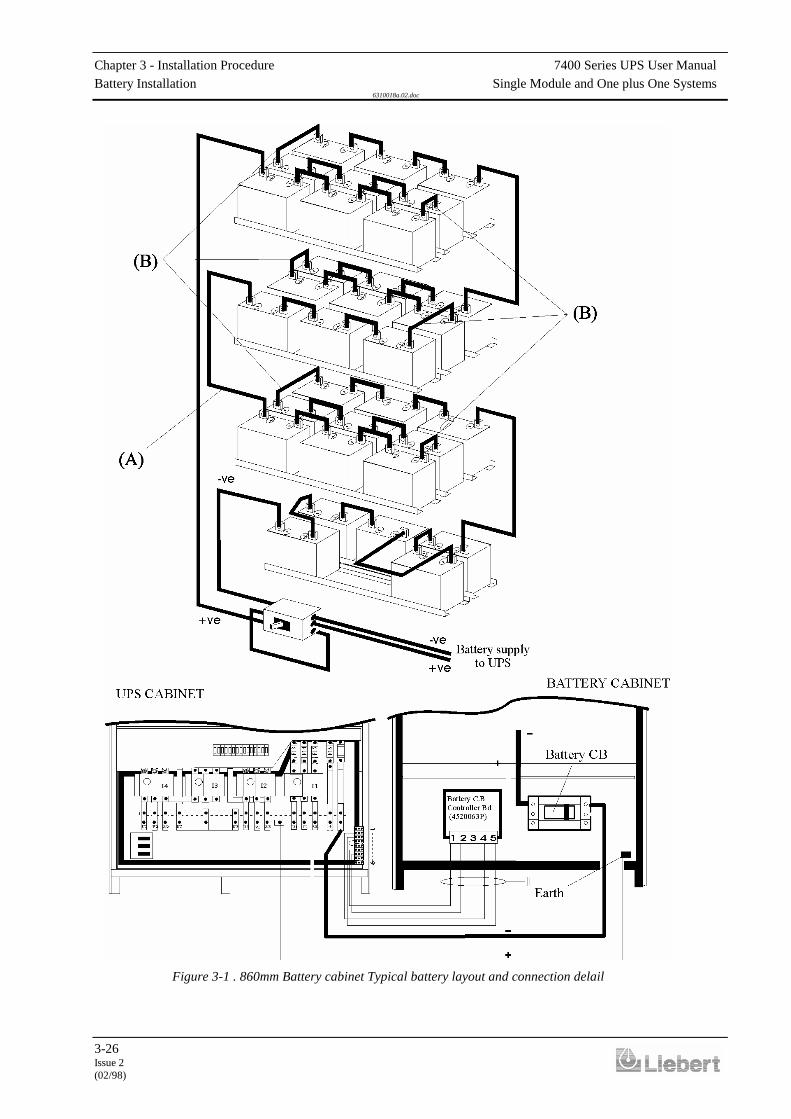
Chapter 3 - Installation Procedure 7400 Series UPS User ManualBattery Installation Single Module and One plus One Systems
6310018a.02.doc
3-26Issue 2(02/98)
Figure 3-1 . 860mm Battery cabinet Typical battery layout and connection delail

7400 Series UPS User Manual Chapter 3 - Installation ProcedureSingle Module and One plus One Systems Battery Installation
6310018a.02.doc
3-27Issue 2
(02/98) LCA 10/01
Figure 3-2 . Typical example of battery cabinet with extension cabinet

Chapter 3 - Installation Procedure 7400 Series UPS User ManualBattery Installation Single Module and One plus One Systems
6310018a.02.doc
3-28Issue 2(02/98)
A battery circuit breaker box houses the battery circuit breaker and its controllerboard and is used to connect the battery to the UPS in installations where thebatteries are not contained in the standard battery cabinet.Several ‘boxes’, of various current ratings, are available and are similar in theirdesign and content. These are listed below:
• 250 Amp C/B Part No4641007H for use with 80 kVA models.
• 400 Amp C/B Part No4641008I for use with 120 kVA model.
• 630 Amp C/B Part No4641009D for use with 200 kVA model.
• 800 Amp C/B Part No4641011L for use with 300 kVA model.
• 1000 Amp C/B Part No4641012M for use with 400 kVA model.
3.5.2 Battery circuit breakerboxes
Figure 3-1 . Battery C/B box connections 80-120 kVA UPS
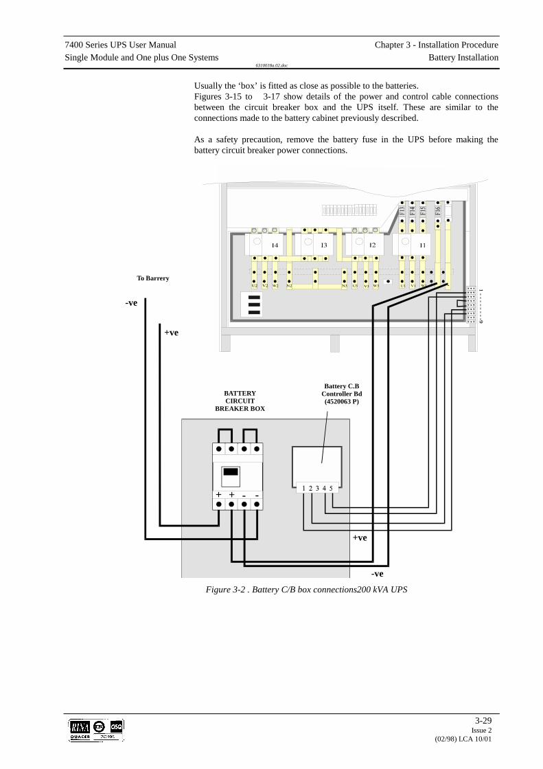
7400 Series UPS User Manual Chapter 3 - Installation ProcedureSingle Module and One plus One Systems Battery Installation
6310018a.02.doc
3-29Issue 2
(02/98) LCA 10/01
Usually the ‘box’ is fitted as close as possible to the batteries.Figures 3-15 to 3-17 show details of the power and control cable connectionsbetween the circuit breaker box and the UPS itself. These are similar to theconnections made to the battery cabinet previously described.
As a safety precaution, remove the battery fuse in the UPS before making thebattery circuit breaker power connections.
-ve
-ve
+ve
+ve
--+ +
To Barrery
BATTERYCIRCUIT
BREAKER BOX
Battery C.BController Bd(4520063 P)
Figure 3-2 . Battery C/B box connections200 kVA UPS
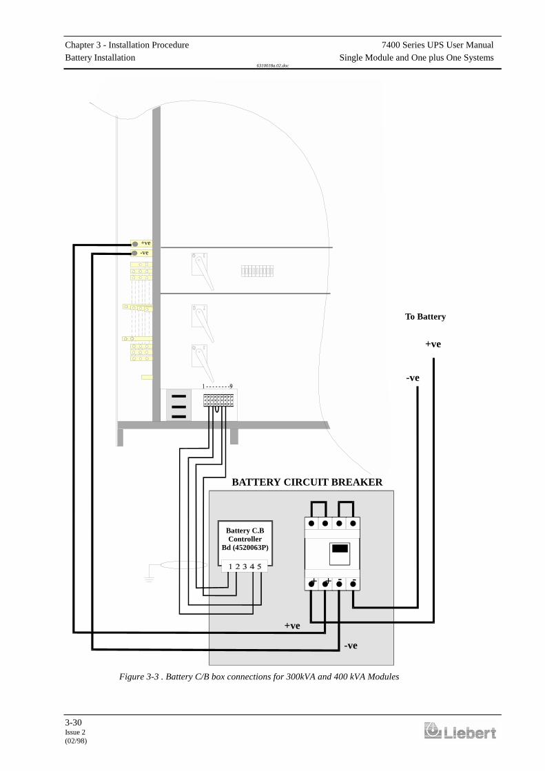
Chapter 3 - Installation Procedure 7400 Series UPS User ManualBattery Installation Single Module and One plus One Systems
6310018a.02.doc
3-30Issue 2(02/98)
-ve
-ve
+ve
+ve
- -++
-ve+ve
To Battery
BATTERY CIRCUIT BREAKER
Battery C.BController
Bd (4520063P)
Figure 3-3 . Battery C/B box connections for 300kVA and 400 kVA Modules
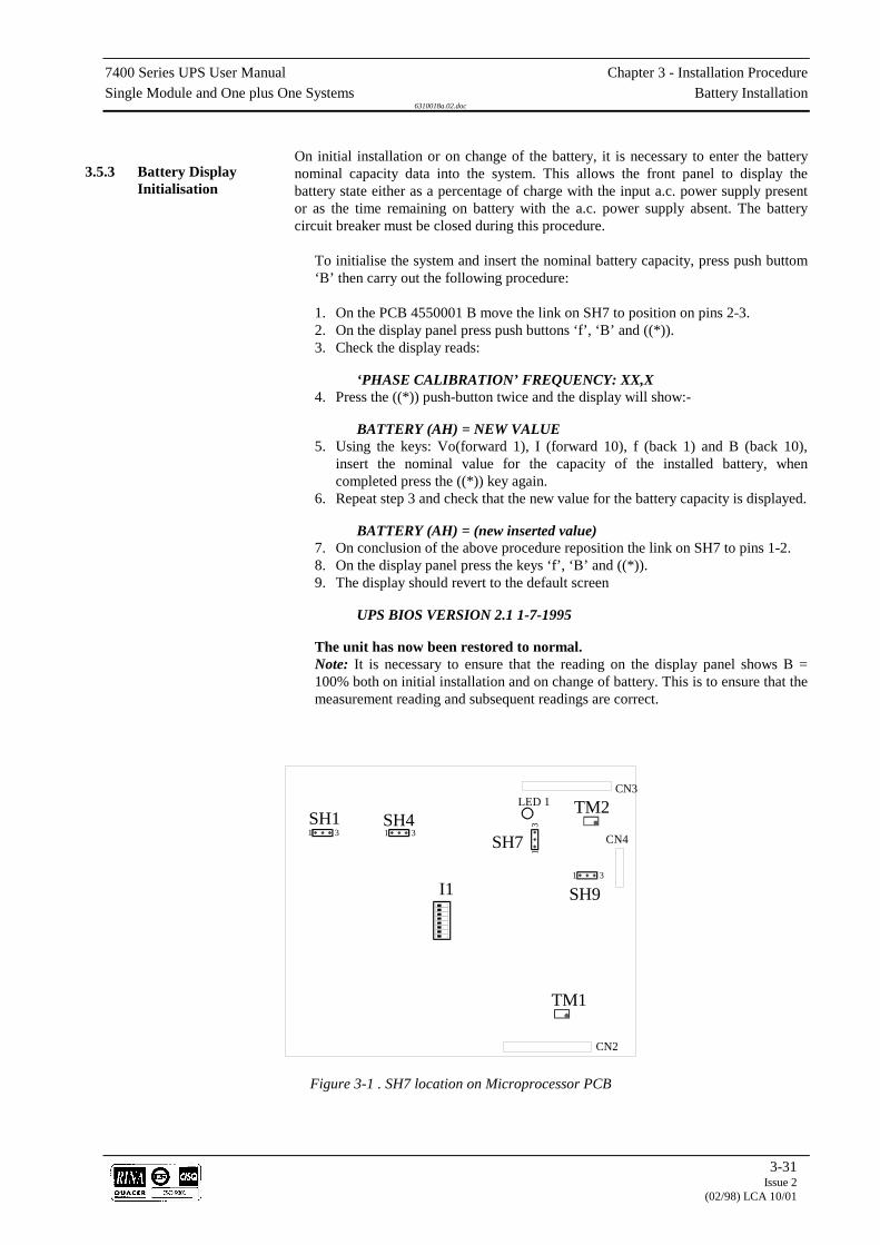
7400 Series UPS User Manual Chapter 3 - Installation ProcedureSingle Module and One plus One Systems Battery Installation
6310018a.02.doc
3-31Issue 2
(02/98) LCA 10/01
On initial installation or on change of the battery, it is necessary to enter the batterynominal capacity data into the system. This allows the front panel to display thebattery state either as a percentage of charge with the input a.c. power supply presentor as the time remaining on battery with the a.c. power supply absent. The batterycircuit breaker must be closed during this procedure.
To initialise the system and insert the nominal battery capacity, press push buttom‘B’ then carry out the following procedure:
1. On the PCB 4550001 B move the link on SH7 to position on pins 2-3.2. On the display panel press push buttons ‘f’, ‘B’ and ((*)).3. Check the display reads:
‘PHASE CALIBRATION’ FREQUENCY: XX,X4. Press the ((*)) push-button twice and the display will show:-
BATTERY (AH) = NEW VALUE5. Using the keys: Vo(forward 1), I (forward 10), f (back 1) and B (back 10),
insert the nominal value for the capacity of the installed battery, whencompleted press the ((*)) key again.
6. Repeat step 3 and check that the new value for the battery capacity is displayed.
BATTERY (AH) = (new inserted value)7. On conclusion of the above procedure reposition the link on SH7 to pins 1-2.8. On the display panel press the keys ‘f’, ‘B’ and ((*)).9. The display should revert to the default screen
UPS BIOS VERSION 2.1 1-7-1995
The unit has now been restored to normal.Note: It is necessary to ensure that the reading on the display panel shows B =100% both on initial installation and on change of battery. This is to ensure that themeasurement reading and subsequent readings are correct.
3.5.3 Battery DisplayInitialisation
1 3 1 3
1 3
13
LED 1
SH7SH1 SH4
SH9I1
TM1
TM2CN3
CN4
CN2
Figure 3-1 . SH7 location on Microprocessor PCB

Chapter 3 - Installation Procedure 7400 Series UPS User ManualBattery Installation Single Module and One plus One Systems
6310018a.02.doc
3-32Issue 2(02/98)

7400 Series UPS User Manual Chapter 4 - Optional equipmentSingle Module and One plus One Systems AS400 Interface Board (4590041B)
6310018a.02.doc
4-1Issue 2
(02/98) LCA 10/01
4. Chapter 4 - Optional equipmentSeveral items of optional equipment are available for fitting to the 7400series UPS for use by the customer as required.These options are:
• IBM AS400 Interface (part no. 4590041 B).
• IBM AS400 Interface with 4-way output (part no. 4590045F).
• External Interface Board (part no. 4590044E).
• Remote Alarms Monitor (part no. 4305001Z).
• Remote alarms and control panel (part no. 4305002A).
• RS232 communications interface (SGC) (part no. 4550002C).
• 5th Harmonic Input filter Option.
• Cable top entry kit for 80 and 120 kVA (part no. 2174011V).
• Cable top entry kit for 200 kVA (part no. 2174033 R).
• 12 Pulse system option (80,120 and 200 kVA).
• Option Kit (includes Batt. Temp. compensation; Input currentlimit; Batt. Current limit) (part no. 77000005).

Chapter 4 - Optional equipment 7400 Series UPS User ManualAS400 Interface Board (4590041 B) Single Module and One plus One Systems
6310018a.02.doc
4-2Issue 2(02/98)
4.1 AS400 Interface Board (4590041B)
The AS400 Interface board connects the five most operationally criticalUPS alarms to an IBM AS400 computer, which is designed to monitorsuch alarms and respond to their appearance.The alarms in question are:
• Mains failure
• Load on inverter
• Low battery and/or battery circuit breaker open
• Load on mains (bypass)
• Load on maintenance bypassThese alarm signals are provided by volt-free relay contacts.The AS400 Interface Board is fitted to the bottom of the UPS cabinet doorand connected to the UPS control electronics by a ribbon cable (FC13 inthe 80/120/200 kVA models and FC19 in the 300 - 400kVA models )which is fitted to all modules and normally stowed in the cable loom whenthis option is not used.
Two female D-type connectors are provided on the Interface Board toenable the above signals to be connected to the AS400 computer. Oneconnector, CN1, has 9 pins and the other, CN2, has 15. Figure 4-1provides pin-out details for these connectors.
Note: Use one connector only -i.e.don't use both connectors simultaneously.
In addition to the D-type connectors, the AS400 Interface Board alsocontains a number of volt-free relays whose contacts provide a duplicateset of volt-free alarm outputs that are connected to terminal block M1Äas shown in figure 4-1. These outputs can be used to drive an externalalarms monitoring device. Maximum contact rating on M1 terminals =50 Vcc @ 1 Amp.
Note: When using the above contacts for remote alarm annunciation, thepower supply for the remote indicators must be provided from an externalpower source. Under no circumstances should the UPS internal low voltage
supplies be used for this purpose.
The Interface Board has facilities to accept two remote control inputs, asshown in figure 4-1. One remote input allows the inverter to be shutdown (transferring the load to the bypass supply) and the other enablesthe inverter synchronisation feature to be inhibited. The invertersynchronisation inhibit feature is most often used if the UPS is poweredfrom a standby generator when the input mains supply fails and the
generator frequency is unstable.
The external control signals (12V dc or ac) should be connected toterminal block M2 as shown in figure 4-1. Once again, the voltageapplied to these terminals must be generated by an external power sourceand not taken from the UPS internal low voltage supplies.
When fitting the AS400 interface board to the 7400 series, ensure thatlink SH-1 is in position 1-2.
4.1.1 AS400 Interface Boardoutputs
4.1.2 Remote control inputs
4.1.3 Calibration
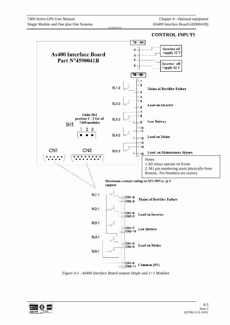
7400 Series UPS User Manual Chapter 4 - Optional equipmentSingle Module and One plus One Systems AS400 Interface Board (4590041B)
6310018a.02.doc
4-3Issue 2
(02/98) LCA 10/01
Figure 4-1 . AS400 Interface Board outputs Single and 1+1 Modules
Notes:1.All relays operate on Event2. M1 pin numbering starts physically fromBottom.. Pin Numbers are correct.
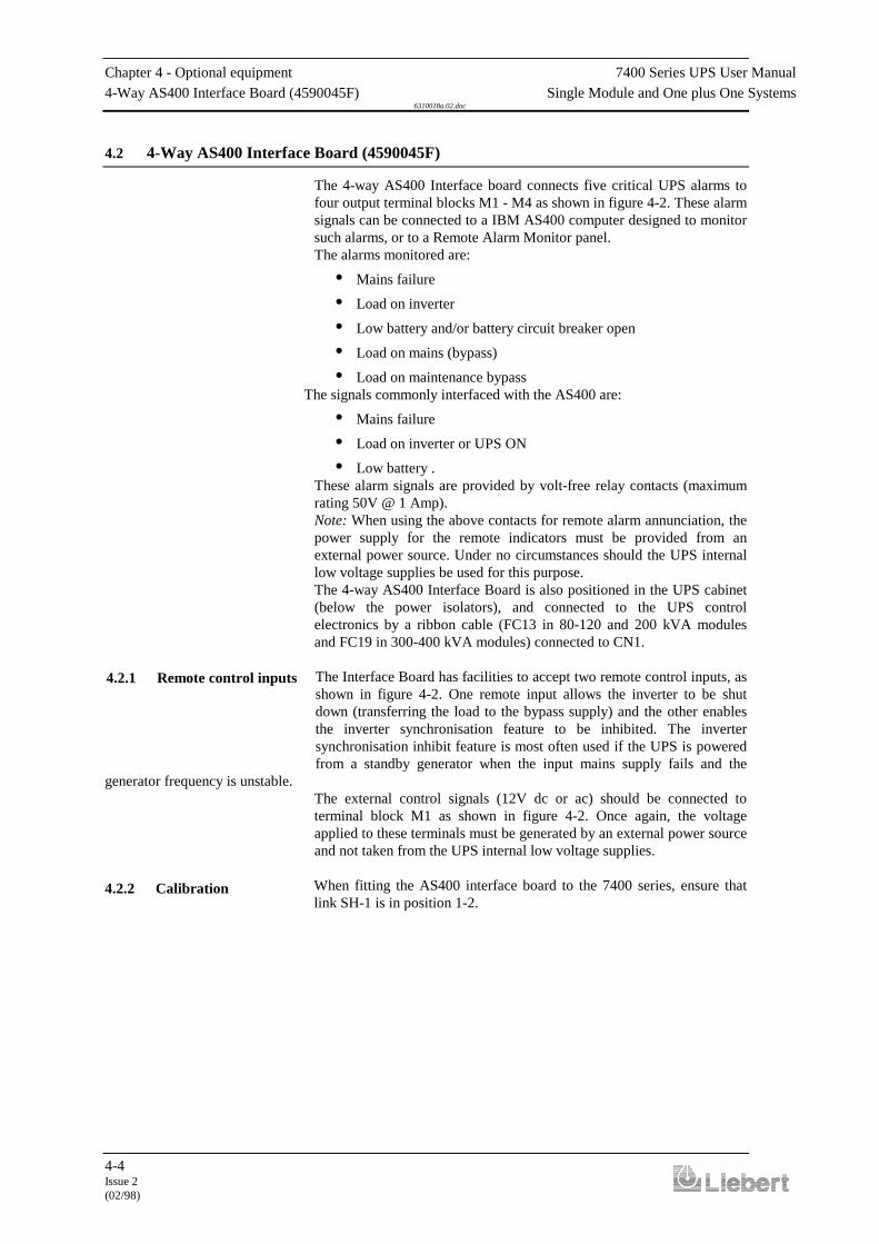
Chapter 4 - Optional equipment 7400 Series UPS User Manual4-Way AS400 Interface Board (4590045F) Single Module and One plus One Systems
6310018a.02.doc
4-4Issue 2(02/98)
4.2 4-Way AS400 Interface Board (4590045F)
The 4-way AS400 Interface board connects five critical UPS alarms tofour output terminal blocks M1 - M4 as shown in figure 4-2. These alarmsignals can be connected to a IBM AS400 computer designed to monitorsuch alarms, or to a Remote Alarm Monitor panel.The alarms monitored are:
• Mains failure
• Load on inverter
• Low battery and/or battery circuit breaker open
• Load on mains (bypass)
• Load on maintenance bypassThe signals commonly interfaced with the AS400 are:
• Mains failure
• Load on inverter or UPS ON
• Low battery .These alarm signals are provided by volt-free relay contacts (maximumrating 50V @ 1 Amp).Note: When using the above contacts for remote alarm annunciation, thepower supply for the remote indicators must be provided from anexternal power source. Under no circumstances should the UPS internallow voltage supplies be used for this purpose.The 4-way AS400 Interface Board is also positioned in the UPS cabinet(below the power isolators), and connected to the UPS controlelectronics by a ribbon cable (FC13 in 80-120 and 200 kVA modulesand FC19 in 300-400 kVA modules) connected to CN1.
The Interface Board has facilities to accept two remote control inputs, asshown in figure 4-2. One remote input allows the inverter to be shutdown (transferring the load to the bypass supply) and the other enablesthe inverter synchronisation feature to be inhibited. The invertersynchronisation inhibit feature is most often used if the UPS is poweredfrom a standby generator when the input mains supply fails and the
generator frequency is unstable.The external control signals (12V dc or ac) should be connected toterminal block M1 as shown in figure 4-2. Once again, the voltageapplied to these terminals must be generated by an external power sourceand not taken from the UPS internal low voltage supplies.
When fitting the AS400 interface board to the 7400 series, ensure thatlink SH-1 is in position 1-2.
4.2.1 Remote control inputs
4.2.2 Calibration
7400 Series UPS User Manual Chapter 4 - Optional equipmentSingle Module and One plus One Systems 4-Way AS400 Interface Board (4590045F)
6310018a.02.doc
4-5Issue 2
(02/98) LCA 10/01
Figure 4-1 . Four output AS400 interface board
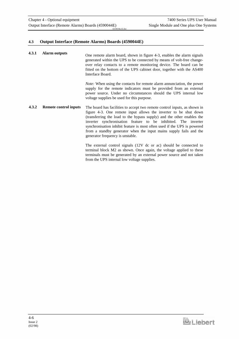
Chapter 4 - Optional equipment 7400 Series UPS User ManualOutput Interface (Remote Alarms) Boards (4590044E) Single Module and One plus One Systems
6310018a.02.doc
4-6Issue 2(02/98)
4.3 Output Interface (Remote Alarms) Boards (4590044E)
One remote alarm board, shown in figure 4-3, enables the alarm signalsgenerated within the UPS to be connected by means of volt-free change-over relay contacts to a remote monitoring device. The board can befitted on the bottom of the UPS cabinet door, together with the AS400Interface Board.
Note: When using the contacts for remote alarm annunciation, the powersupply for the remote indicators must be provided from an externalpower source. Under no circumstances should the UPS internal lowvoltage supplies be used for this purpose.
The board has facilities to accept two remote control inputs, as shown infigure 4-3. One remote input allows the inverter to be shut down(transferring the load to the bypass supply) and the other enables theinverter synchronisation feature to be inhibited. The invertersynchronisation inhibit feature is most often used if the UPS is poweredfrom a standby generator when the input mains supply fails and thegenerator frequency is unstable.
The external control signals (12V dc or ac) should be connected toterminal block M2 as shown. Once again, the voltage applied to theseterminals must be generated by an external power source and not takenfrom the UPS internal low voltage supplies.
4.3.1 Alarm outputs
4.3.2 Remote control inputs
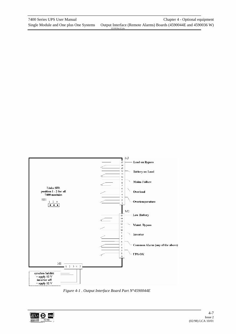
7400 Series UPS User Manual Chapter 4 - Optional equipmentSingle Module and One plus One Systems Output Interface (Remote Alarms) Boards (4590044E and 4590036 W)
6310018a.02.doc
4-7Issue 2
(02/98) LCA 10/01
Figure 4-1 . Output Interface Board Part N°4590044E
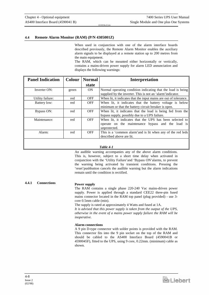
Chapter 4 - Optional equipment 7400 Series UPS User ManualAS400 Interface Board (4590041 B) Single Module and One plus One Systems
6310018a.02.doc
4-8Issue 2(02/98)
4.4 Remote Alarm Monitor (RAM) (P/N 4305001Z)
When used in conjunction with one of the alarm interface boardsdescribed previously, the Remote Alarm Monitor enables the auxiliaryalarm signals to be displayed at a remote station up to 200 metres fromthe main equipment.The RAM, which can be mounted either horizontally or vertically,contains a mains-driven power supply for alarm LED annunciation anddisplays the following warnings:
Panel Indication Colour Normalstate
Interpretation
Inverter ON: green ON Normal operating condition indicating that the load is beingsupplied by the inverter. This is not an ‘alarm’indicator.
Utility failure: red OFF When lit, it indicates that the input mains are out of tolerance.Battery low: red OFF When lit, it indicates that the battery voltage is below
minimum or that the battery circuit breaker is open.Bypass ON: red OFF When lit, it indicates that the load is being fed from the
bypass supply, possibly due to a UPS failure.Maintenance: red OFF When lit, it indicates that the UPS has been selected to
operate on the maintenance bypass and the load isunprotected.
Alarm: red OFF This is a ‘common alarm’and is lit when any of the red ledsdescribed above are lit.
Table 4-1An audible warning accompanies any of the above alarm conditions.This is, however, subject to a short time delay when activated inconjunction with the ‘Utility Failure’and ‘Bypass ON’alarms, to preventthe warning being activated by transient conditions. Pressing the‘reset’pushbutton cancels the audible warning but the alarm indicationsremain until the condition is rectified.
Power supplyThe RAM contains a single phase 220-240 Vac mains-driven powersupply. Power is applied through a standard CEE22 three-pin fusedmains connector located in the RAM top panel (plug provided) - use 3-core 0.5mm cable (min).The supply is rated at approximately 4 Watts and fused at 1A.It is advised that this power supply is taken from the output of the UPS,otherwise in the event of a mains power supply failure the RAM will beinoperative.
Alarm connectionsA 9 pin D-type connector with solder points is provided with the RAM.This connector fits into the 9 pin socket on the top of the RAM andshould be cabled to the AS400 Interface Board (4590041B or4590045F), fitted to the UPS, using 9 core, 0.22mm. (minimum) cable asshown.
4.4.1 Connections

7400 Series UPS User Manual Chapter 4 - Optional equipmentSingle Module and One plus One Systems Remote Alarm Monitor (RAM) (P/N 4305001Z)
6310018a.02.doc
4-9Issue 2
(02/98) LCA 10/01
Figure 4-1 . Remote Alarm Monitor connection details
for both the single way (on the left) and four way (on the right) Interface boards.

7400 Series UPS User Manual Chapter 4 - Optional equipmentSingle Module and One plus One Systems Remote Alarm and Control Panel (Part No. 4305002 A)
6310018a.02.doc
4-10Issue 2(02/98)
4.5 Remote Alarm and Control Panel (Part No. 4305002 A)
When used in conjunction with the Output Interface Board (4590044E)described previously, the Remote Alarm and Control Panel enables thealarm signals to be displayed at a remote station up to 100 metres awayfrom the main equipment. In addition the panel allows the operator toswitch OFF the UPS inverters.
The Remote Alarm and Control Panel, which can be mounted eitherhorizontally or vertically, contains a mains driven power supply foralarm LED annunciation. An audible warning accompanies any of thealarm indications after a short time delay, this can be silenced by theoperator.The following list gives an interpretation of the controls and alarmfacilities:
Panel Indication Priority IdentFig. 4-5
Colour NormalState
Interpretation
BATTERY ON LOAD Alarm 8 red OFF This is a status alarm showing a UPS is runningon the battery, this may be accompanied with amains fault alarm and the indication from theassociated UPS (6) changing from green to red.
LOW BATTERY Alarm 9 red OFF This indicates that either the battery voltage islow or the battery circuit breaker is open andwould normally follow the BATTERY ONLOAD (8) alarm. The indication from theassociated UPS (6) will change from green tored.
OVERLOAD Alarm 10 red OFF This indicates that the system has reached100% load, after a short period of time it willbe accompanied by the LOAD ON MAINS(15) alarm. The indication from the associatedUPS (6) will change from green to red.
OVER-TEMPERATURE
Alarm 11 red OFF If an over temperature condition arises the unitinvolved will shut down after 3 minutes, shouldthis exceed the module redundancy the systemwill switch to the bypass. This may beaccompanied by a UPS FAULT alarm (13) andthe indication from the associated UPS (6)changing from green to red.
MAINS FAULT Alarm 12 red OFF This indicates that the mains power has eitherfailed or is out of the specified range. This maybe accompanied by a BATTERY ON LOADalarm (8) and the indication from the associatedUPS (6) changing from green to red.
UPS FAULT Alarm 13 red OFF This is taken from the UPS common alarmoutput and would normally be accompaniedwith a UPS alarm and the indication from theassociated UPS (6) changing from green to red.
MAINTENANCEBYPASS
Alarm 14 red OFF This indicates that the UPS system has beenselected to run on the maintenance bypasssupplies and the load is unprotected fromdisturbances.
LOAD ON MAINS Alarm 15 red OFF This is a status alarm warning that the load isbeing powered through the static bypass systemand is therefore unprotected.
4.5.1 Introduction

7400 Series UPS User Manual Chapter 4 - Optional equipmentSingle Module and One plus One Systems Remote Alarm and Control Panel (Part No. 4305002 A)
6310018a.02.doc
4-11Issue 2
(02/98) LCA 10/01
Panel Indication Priority IdentFig. 4-5
Colour NormalState
Interpretation
UPS Module status status 6 red/green
ONgreen
These are bi-coloured indicators, when lit greenindicate that the UPS is OK, and when lit redindicate that a fault is present. Indication fornumber 1 module is on the left and number 2module next to it, the other four indicators arenot used for this application.
Mains OK status 21 green ON When lit indicates that the mains supply to themodules is OK and therefore bypass suppliesare available.
Load on Mains status 19 green OFF When lit indicates that the load has transferredto the bypass supplies and is thereforeunprotected.
UPS OK status 20 green ON When lit indicates that the UPS inverters aresynchronised and UPS supplies are available.
Load on UPS status 18 green ON When lit this indicates that the load is beingsupplied by the UPS inverters - the normalstatus.
UPS OFF status 17 red OFF This shows that the UPS OFF switch, on theremote panel has been operated and theinverters have been shut down, the load will besupplied via the bypass if available.
UPS OFF switch 16 OFF This switch selects all the UPS inverters OFF.It can only be used when enabled by the keyenable switch (4). The UPS OFF indication(17) accompanies its operation.
Alarm silence switch 7 OFF This switch silences the horn on the RemoteAlarm and Control panel only, it has no effecton the UPS system or any indications.
UPS OFF enable switch 4 OFF This key operated switch enables the UPS OFFswitch and is security against the UPS OFFswitch being operated accidentally.
Table 4-2
Power SupplyThe panel contains a single phase 220-240 Vac mains driven powersupply. Power is applied through a standard three pin mains connectorlocated at the top of the panel (plug provided) - use 3 core 0.5mm cableminimum.
Alarm connectionsAlarm connections from the UPS modules are provided by connectorsM1 (5 way terminal block), M2 (15 way terminal block) and M3 (15 wayterminal block) on the Output Interface boards (4590044E), to CN1 (50pin D-type connector) on the Remote Alarm and Control panel (4305002A).
Full installation instructions are provided with the option kit.
4.5.2 Connections

7400 Series UPS User Manual Chapter 4 - Optional equipmentSingle Module and One plus One Systems Remote Alarm and Control Panel (Part No. 4305002 A)
6310018a.02.doc
4-12Issue 2(02/98)
Figure 4-1 . UPS System connection and identification of the control and
indication of the Remote Alarms and Control Panel
7400 Series UPS User Manual Chapter 4 - Optional equipmentSingle Module and One plus One Systems RS 232 Communications Management Board (SGC) (4550002C)
6310018a.02.doc
4-13Issue 2
(02/98) LCA 10/01
UPS 1(or Single Module)
Remote Alarm andControl Panel
UPS 2(when 1 + 1 system)
Remote Alarm andControl Panel
Interface boardPt. No. 4590044 E
Pt. No. 4305002 A Interface boardPt. No. 4590044 E
Pt. No. 4305002 A
M3 Terminals CN1 Pins M3 Terminals CN1 Pins15 15 15 1014, 11, 8, 5, 2 29 14, 11, 8, 5, 2 2412 33 12 289 17 9 126 31 6 263 14 3 9
M2 Terminals M2 Terminals15 30 15 2514, 11, 8, 5, 2 46 14, 11, 8, 5, 2 4112 13 12 89 16 9 116 32 6 273 49 3 442 50 2 45
M1 Terminals M1 Terminals5 47 5 424 48 4 43
Table 4-3
UPS module Interface board terminal connections to Remote alarm and control panel socket pins.
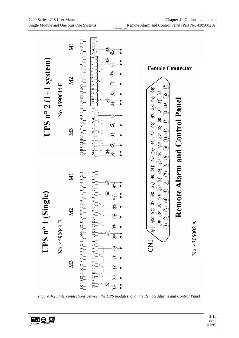
7400 Series UPS User Manual Chapter 4 - Optional equipmentSingle Module and One plus One Systems Remote Alarm and Control Panel (Part No. 4305002 A)
6310018a.02.doc
4-14Issue 2(02/98)
Figure 4-2 . Interconnections between the UPS modules and the Remote Alarms and Control Panel

7400 Series UPS User Manual Chapter 4 - Optional equipmentSingle Module and One plus One Systems RS 232 Communications Management Board (SGC) (4550002C)
6310018a.02.doc
4-15Issue 2
(02/98) LCA 10/01
4.6 RS 232 Communications Management Board (SGC) (4550002C)
The optional RS232 Communications Management Board takes existinginformation available from the display
assembly, stores it and converts it into a customer usable form for displayeither locally or remote to the UPS. It can be interrogated via a telephone-modem system from a remote service centre and it can activate a remotestation in the event of an alarm to down-load the current status.
Figure 4-7 shows a typical system using the RS232 CommunicationsManagement Board, which is referred to as the SGC (Scheda GestioneCommunicazione). One would be fitted to the MSSC for systeminformation and one to each UPS module for individual moduleinformation. The SGC has two outputs; the first, as shown, is the modemconnection and the second connects directly into a PC for localmonitoring where required.Remote communications can be via a dedicated telephone line or a nondedicated line, in the second case a "Data Switch" will be required toselect the modem connected to the UPS when required.The information stored on this board is maintained in the event of a UPSshutdown by (alkaline) batteries. These batteries also maintain an on-board clock which times and dates events as they occur.The SGC board continually stores information on the dynamic powerparameters within the UPS. Four hundred of these events are stored in arecirculating memory, the most recent displacing the earliest in the‘Power History’store. A similar ‘Event History’store tracks the changingoperational status of the machine. This memory reflects the alpha-numeric display on the front panel and updates whenever a change takesplace. The message would normally read ‘NORMAL OPERATION’ butwould change when a ‘WARNING’ or ‘ALARM’ condition occurred. Ifan ‘ALARM’ occurs the SGC board marks the event in the ‘PowerHistory’and after a further 199 events, the system locks out any furtherupdates. This gives a snap-shot of the events on either side of the alarm.On ‘ALARM’ the SGC board can be configured to automatically dial outto the remote site or service centre. Two telephone numbers can bestored within the memory. The primary number will be triedpreferentially but the system will revert to the secondary number shouldthe primary connection prove unsuccessful.An LED located on the SGC board flashes at two hertz per second whencommunication is taking place.A software package is provided with the option to be used with the PC.This software is used to configure the system and to run the diagnostics.It has a screen driven menu with an on screen help facility. The softwarecan be operated in several languages which are set up at the terminal.Each terminal can be set up to monitor 1000 UPS.
The remote terminal, as well as receiving information from the UPS, caninterrogate the system. It can do this in two ways:
1. Manual input from the keyboard will allow the operator to select anyone of the UPS on the system and request the current status.
2. The operator may select any or all the UPS from a list residing in the
computer and call automatically, overnight if necessary.
4.6.1 Introduction
Chapter 4 - Optional equipment 7400 Series UPS User ManualRS 232 Communications Management Board (SGC) (4550002C) Single Module and One plus One Systems
6310018a.02.doc
4-16Issue 2(02/98)
The system is made up of the following parts or sub-systems:
1. RS 232 Communications Management Board (SGC), for installationwithin the UPS.
2. Batteries: these may be of any non-rechargeable type (alkaline, ‘environment-
friendly', etc.) as long as they are of the correct size (AAA).
3. Personal computer for local connection 4. Flat, 25-wire cable ending in two 25 pin connectors, one male and
one female, for UPS-PC connection. 5. Digital telephone modem for connection to the board. 6. Flat, 25-wire cable ending in two 25 pin connectors, one male and
one female, for local UPS- modem connection. 7. Personal computer plus digital telephone modem for remote station. 8. Flat, 25-wire cable ending in two 25 pin connectors, one male and
one female, for remote modem-PC connection.
The possible types of connection, as shown in figure 4-8 , are as follows:
Direct ConnectionThis type of connection requires items 1, 2, 3, and 4 from the above list.It is possible to obtain data from a distance of upto 15 metres through theEIA RS232E interface.
Remote Connection (i.e. via telephone modem)This type of connection requires items 1, 2, 5, 6, 7, 8 and a commutedtelephone line.
Complete ConnectionComplete connection require the total resources of the above.Full installation and operating instructions are supplied with the option.
4.6.2 General Information

7400 Series UPS User Manual Chapter 4 - Optional equipmentSingle Module and One plus One Systems RS 232 Communications Management Board (SGC) (4550002C)
6310018a.02.doc
4-17Issue 2
(02/98) LCA 10/01
Figure 4-1 . Typical Series 7400 RS232 Communications configuration

Chapter 4 - Optional equipment 7400 Series UPS User Manual5th Harmonic Input Filter Single Module and One plus One Systems
6310018a.02.doc
4-18Issue 2(02/98)
4.7 5th Harmonic Input Filter
An optional input 5th harmonic filter can be added to the 6 pulse 7400series UPS to improve the UPS input power factor and reduce theamount of electrical noise reflected into the input three phase supply.
On units upto 200 kVA the filter components are contained in a purpose-built cabinet which is positioned alongside the main UPS equipment andconnected in series with the UPS input supply. In the case of the 300/400kVA models the input filter is located within the UPS as illustrated infigure 4-12. The filter components are matched to the UPS capacity,resulting in different part numbers for each system as follows:
Part No. Weight80kVA filter cabinet 5331016 C 220kg.120kVA filter cabinet 5331018 E 240kg.200 kVA filter cabinet 5331020 G 280kg.300 kVA filter (internal) 4641010 K N/A400 kVA filter (internal) 4641013 N N/A
Input voltage 380-400-415, three phase.Input voltage tolerance ±15%.Nominal frequency 50Hz.Input frequency tolerance ±5%.UPS input current distortion 10% max. at full load.UPS input power factor >0.9 lag.Dimensions (80-120 kVA) 600 x 800 x 1800 mm.Dimensions (200 kVA) 600 x 800 x 1900 mm.
The 80 - 200 kVA module input filters have a manually operated isolatorI2 plus internal fuse protection. The 300 kVA and 400 kVA filter whenfitted is connected permanently in circuit between the UPS input isolatorand inductor L1. The circuit position of both types of filter are shown infigure 4-8.The block diagram in figure 4-9 and the models’connections in figures 4-9, 10, and 11 , illustrate the installation with a "split bypass" supplyconfiguration.Note: The input Neutral connection must always be connected to thebypass input ‘N3’on the UPS.If the UPS is configured to operate with a "common bypass", a threephase supply with a separate neutral, or a standard four wire input, maybe used. The bypass supplies may be linked via the input connections ofthe filter input isolator I1 or at a junction box/external isolator prior tothe supplies entering the filter cabinet. Ensure all internal links betweenthe UPS input and bypass bus bars are removed so that the filter does notcarry any bypass supplies. The Neutral must be terminated at the UPSbypass input terminal ‘N3', as shown in figure 4-11 for the 200 kVAmodel.Note: The Neutral connection ‘N1’on each input filter Isolator I1 is aconvenient point to terminate or link the Neutral cable. It is notconnected internally to the input filter.
4.7.1 Introduction
4.7.2 Specification
4.7.3 Notes on connection
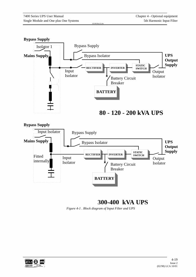
7400 Series UPS User Manual Chapter 4 - Optional equipmentSingle Module and One plus One Systems 5th Harmonic Input Filter
6310018a.02.doc
4-19Issue 2
(02/98) LCA 10/01
Bypass Supply
Mains Supply
Bypass Supply
Mains Supply
Isolator 1 Bypass Supply
Bypass Isolator
InputIsolator
RECTIFIER INVERTERSTATICSWITCH
Battery CircuitBreaker
BATTERY
80 - 120 - 200 kVA UPS
UPSOutputSupply
OutputIsolator
UPSOutputSupply
OutputIsolator
Bypass Supply
Bypass Isolator
InputIsolator
RECTIFIER INVERTERSTATICSWITCHFitted
internally
Input Isolator
Battery CircuitBreaker
BATTERY
300-400 kVA UPSFigure 4-1 . Block diagram of Input Filter and UPS
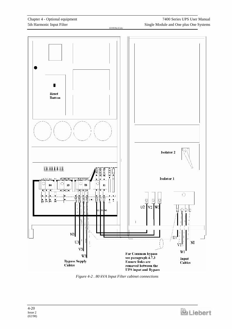
Chapter 4 - Optional equipment 7400 Series UPS User Manual5th Harmonic Input Filter Single Module and One plus One Systems
6310018a.02.doc
4-20Issue 2(02/98)
Figure 4-2 . 80 kVA Input Filter cabinet connections
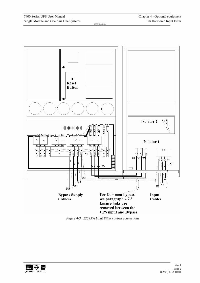
7400 Series UPS User Manual Chapter 4 - Optional equipmentSingle Module and One plus One Systems 5th Harmonic Input Filter
6310018a.02.doc
4-21Issue 2
(02/98) LCA 10/01
Figure 4-3 . 120 kVA Input Filter cabinet connections
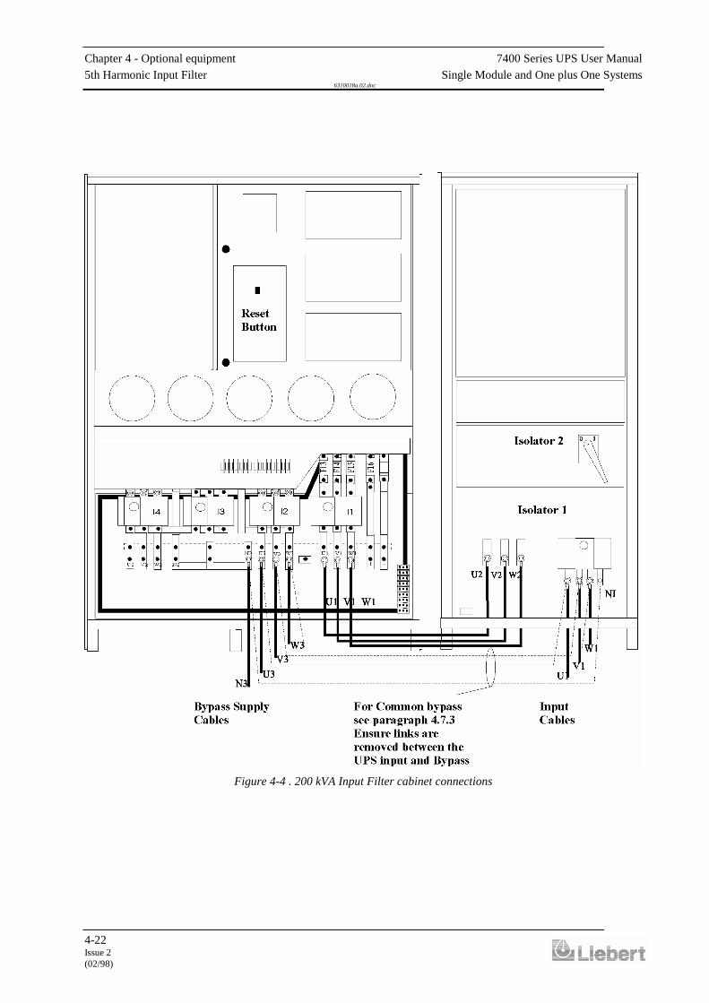
Chapter 4 - Optional equipment 7400 Series UPS User Manual5th Harmonic Input Filter Single Module and One plus One Systems
6310018a.02.doc
4-22Issue 2(02/98)
Figure 4-4 . 200 kVA Input Filter cabinet connections
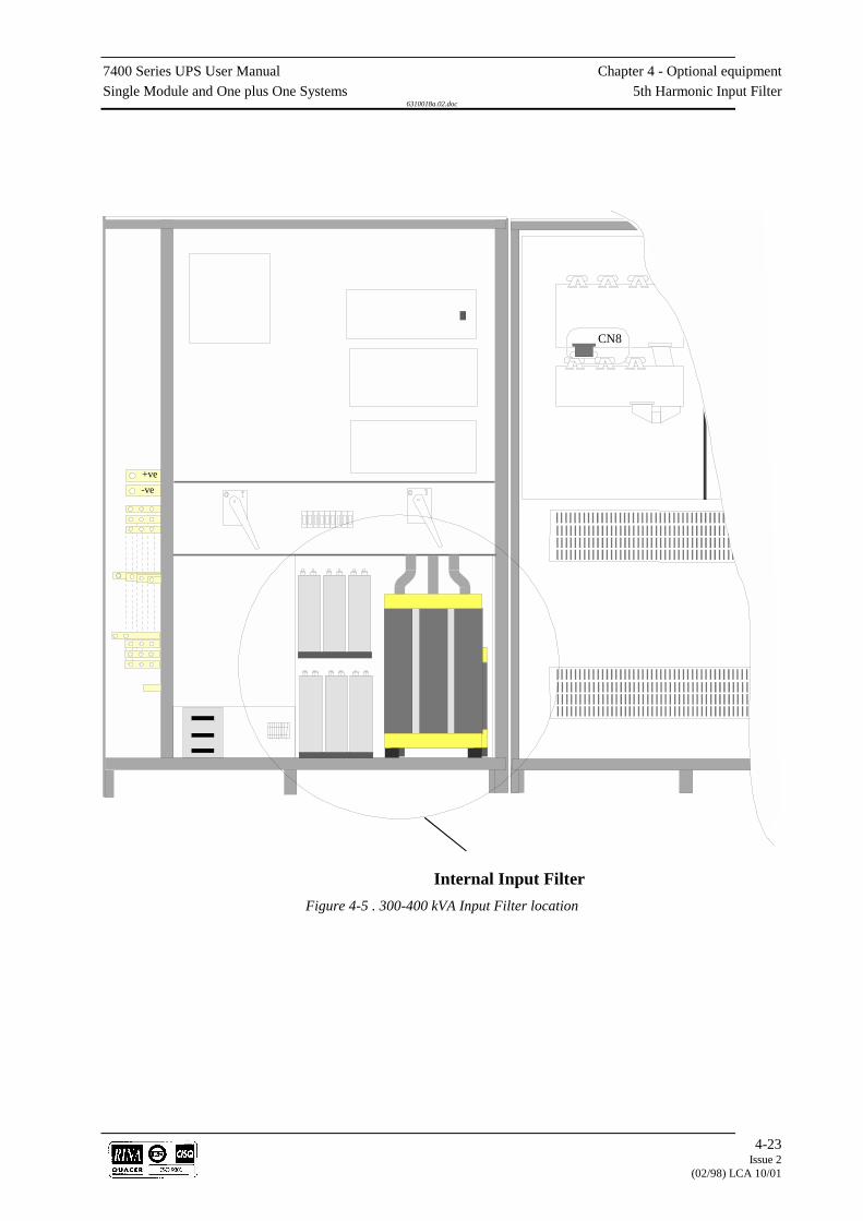
7400 Series UPS User Manual Chapter 4 - Optional equipmentSingle Module and One plus One Systems 5th Harmonic Input Filter
6310018a.02.doc
4-23Issue 2
(02/98) LCA 10/01
-ve+ve
CN8
Internal Input FilterFigure 4-5 . 300-400 kVA Input Filter location

Chapter 4 - Optional equipment 7400 Series UPS User ManualOption Board Kit (Part no. 77000005) Single Module and One plus One Systems
6310018a.02.doc
4-24Issue 2(02/98)
4.8 Cable top entry kit
This modification kit is for use with 80 kVA 120 kVA and 200 kVAmodels only.
As can be seen in figure 4-13 this kit comprises front, rear and top panelswhich when assembled using the extension brackets and existing UPSend panel, allows you to extend the UPS width by approximately200mm. This then allows cable entry through the top aluminium panel. Itis necessary for the user to size and cut holes in the top panel for thecables to be used.
4.8.1 Introduction
CABLE TOPENTRY EXTENSION
Existing UPSside panel
Existing UPSside panel
FRONT VIEW
Extension bracket
SIDE VIEW
Front panelRearpanel
Cablesecuring
UPS Cabinet
Figure 4-1 . Cable Top Entry Kit

7400 Series UPS User Manual Chapter 4 - Optional equipmentSingle Module and One plus One Systems Option Board Kit (Part no. 77000005)
6310018a.02.doc
4-25Issue 2
(02/98) LCA 10/01
4.9 Pulse Option
The 12 pulse option for the series 7400 UPS is normally factory fitted.The power and control cable connections for all units are identical tothose given in chapter 3 of this manual. The 300/400 kVA units have theoption fitted into the existing cabinet. However, for 80, 120 and 200kVA units with part numbers as indicated in the front of this manual, theoption can be fitted on site by a Liebert certified service engineer. Theoption is fitted into a purpose designed cabinet that when bolted to theside of the UPS cabinet extends the system width by 400mm. As with allseries 7400 bolt-on options, the mechanical connection is achieved byremoving the UPS cabinet side panel; the additional cabinet is thenbolted on to the UPS cabinet at the four corners; the side panel removedfrom the UPS cabinet is then fitted to the additional cabinet side wall tocomplete the system.
For electrical connection of the 12 pulse option part no. 53320001 Z for80 kVA unit 5332002 A for the 120 kVA unit and 5332004 C for the200 kVA refer to figures 4-14 and 4-15 and the following instructions.
The details given in figure 4-15 refer to the 80kVA unit. The 120kVAand 200 kVA units are identical except for the following identificationnumbers:
80kVA 120kVA 200kVA
Connector ident CN3 CN4 CN4Extractor fan VL8 VL10 VL12
WARNINGBEFORE STARTING INSTALLATION OF THIS OPTION ENSURE ALL EXTERNAL
ELECTRICAL POWER SUPPLIES ARE SWITCHED OFF AND MADE SAFE.
DISPLAY THE RELEVANT NOTICES. ENSURE THE BATTERIES ARE ISOLATED
FROM THE UPS. CARRY OUT VOLTAGE CHECKS ON ALL INPUT, OUTPUT AND
BATTERY CONNECTIONS..
1. Gain access to UPS interior, open upper hinged panel. Remove thebus bar +ve and -ve connection links from between the rectifieroutput and the d.c. bus bar.
2. Connect cable 88 from the option cabinet TC4 to the UPS rectifier
output +ve bus bar. 3. Connect cable 89 from the option cabinet L2 (term A1) to the UPS
rectifier output -ve bus bar. 4. Connect cable 49 from the option cabinet L2 (term B) to the UPS
d.c. bus bar +ve connection. 5. Connect cable 50 from the option cabinet L2 (term A) to the UPS
d.c. bus bar -ve connection.
4.9.1 Introduction
4.9.2 Electrical connection
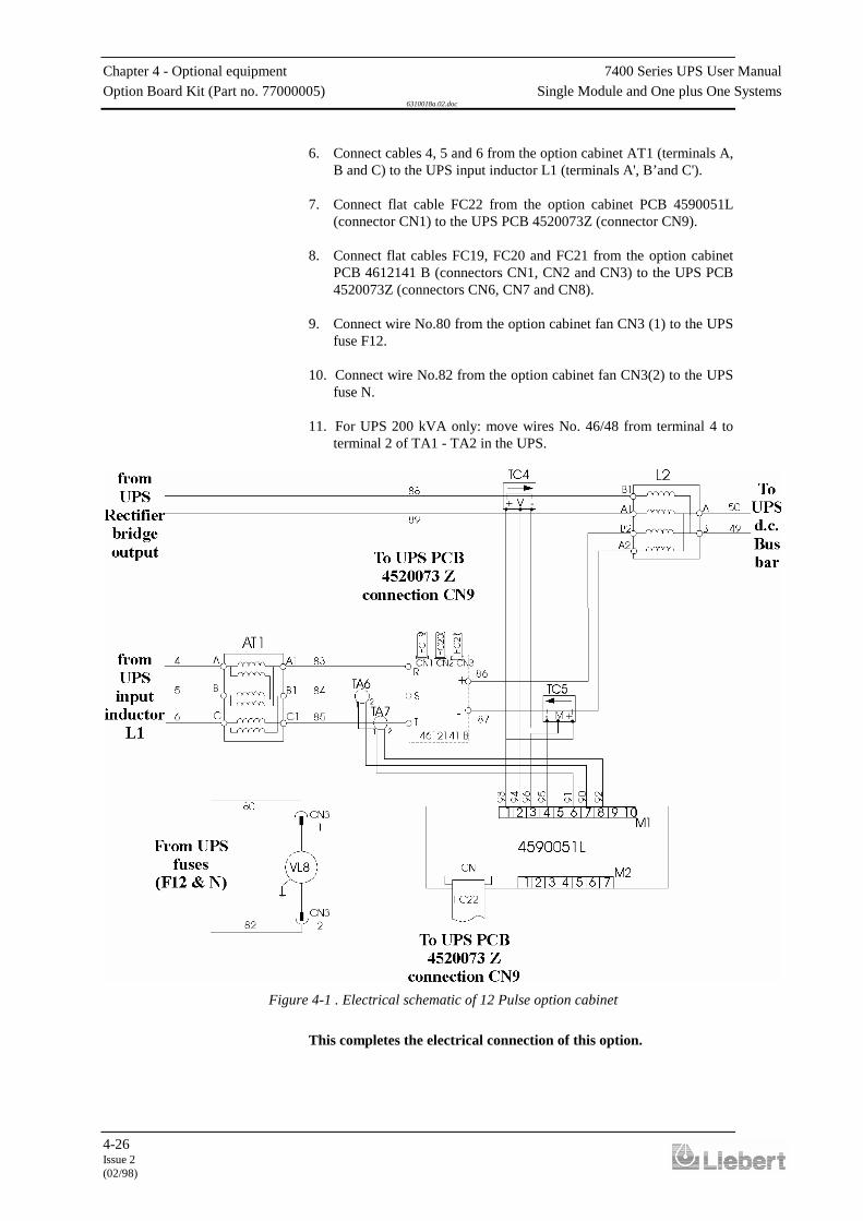
Chapter 4 - Optional equipment 7400 Series UPS User ManualOption Board Kit (Part no. 77000005) Single Module and One plus One Systems
6310018a.02.doc
4-26Issue 2(02/98)
6. Connect cables 4, 5 and 6 from the option cabinet AT1 (terminals A,B and C) to the UPS input inductor L1 (terminals A', B’and C').
7. Connect flat cable FC22 from the option cabinet PCB 4590051L
(connector CN1) to the UPS PCB 4520073Z (connector CN9). 8. Connect flat cables FC19, FC20 and FC21 from the option cabinet
PCB 4612141 B (connectors CN1, CN2 and CN3) to the UPS PCB4520073Z (connectors CN6, CN7 and CN8).
9. Connect wire No.80 from the option cabinet fan CN3 (1) to the UPS
fuse F12. 10. Connect wire No.82 from the option cabinet fan CN3(2) to the UPS
fuse N. 11. For UPS 200 kVA only: move wires No. 46/48 from terminal 4 to
terminal 2 of TA1 - TA2 in the UPS.
This completes the electrical connection of this option.
Figure 4-1 . Electrical schematic of 12 Pulse option cabinet

7400 Series UPS User Manual Chapter 4 - Optional equipmentSingle Module and One plus One Systems Option Board Kit (Part no. 77000005)
6310018a.02.doc
4-27Issue 2
(02/98) LCA 10/01
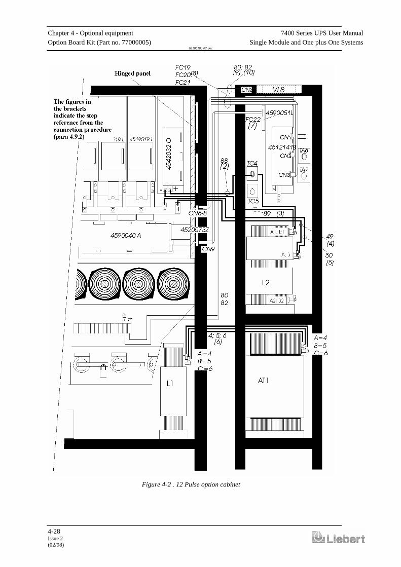
Chapter 4 - Optional equipment 7400 Series UPS User ManualOption Board Kit (Part no. 77000005) Single Module and One plus One Systems
6310018a.02.doc
4-28Issue 2(02/98)
Figure 4-2 . 12 Pulse option cabinet

7400 Series UPS User Manual Chapter 4 - Optional equipmentSingle Module and One plus One Systems Option Board Kit (Part no. 77000005)
6310018a.02.doc
4-29Issue 2
(02/98) LCA 10/01
4.10 Option Board Kit (Part no. 77000005)
This kit is intended for use in to any Series 7400 UPS fitted with theappropriate Rectifier Logic Board (part no. 4520073Z). The kit providesthe following facilities:
p Battery temperature compensation:
With this feature fitted and enabled the nominal float voltagesupplied to the battery is adjusted so as to be inversely proportionalto the ambient battery cabinet/room temperature ( as monitored by aremote temperature sensor ). This prevents the battery being overcharged at high ambient temperatures.Example: - the d.c. float voltage is reduced by 1.5V d.c. per oC risein battery Temperature from 25oC to 35oC.
p Reduced input current limit:
This facility allows the UPS input current limit to be reduced to apredetermined level. This may be necessary when running the UPSon a standby generator. The system is activated by the closure of anormally open contact. The input current limit can be reduced from115% to 50% of nominal.
p Reduced battery current limit:This facility allows the UPS battery current limit ( i.e. the magnitudeof the battery charging current) to be reduced to a preset value. Thismay advisable if the battery cabinet/room ventilation system failed.The system is activated by the closure of a normally open contact.The battery current limit can be reduced from 100% to 10% of itsinitial setting.
Unpack the kit carefully and examine the parts for any signs of transitdamage . Check that the following items are included in the kit:
1 77000002 PCA Option board.1 83696005 Temperature sensor kit.4 49030060 Screws (M3 x 6).
Fit the supplied equipment as follows:
1. If the module is operating and on load, transfer the load to bypassand open the input isolator (I1) following the instructions in chapter2 of this manual.
2. Locate onto the plastic stand-offs and secure the option board into
position as shown in figure 4-16 using the screws provided. 3. Fit links into position on the option board for the features required.
See table 1 for enabling link positions 4. Connect 10 way ribbon cable between PL1 on the option board and
connection CNx on the Rectifier Logic board following existingcable routes.
5. The remote temperature sensor required for the battery temperature
compensation feature should be located in such a position so as tomonitor the ambient air temperature of the battery bank. It isrecommended that the remote sensor is connected to the optionboard using a twisted pair (1-2 mm2) of maximum length 25m.
4.10.1 Introduction
4.10.2 Installation

Chapter 4 - Optional equipment 7400 Series UPS User ManualOption Board Kit (Part no. 77000005) Single Module and One plus One Systems
6310018a.02.doc
4-30Issue 2(02/98)
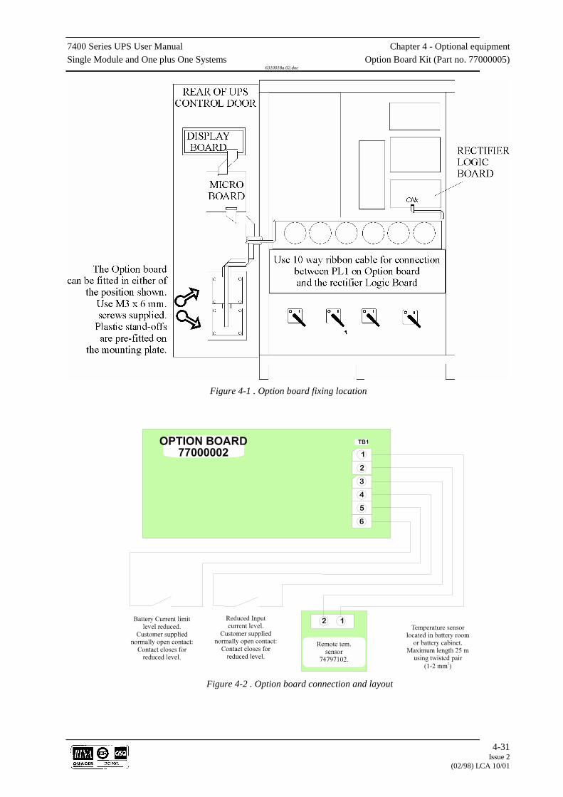
7400 Series UPS User Manual Chapter 4 - Optional equipmentSingle Module and One plus One Systems Option Board Kit (Part no. 77000005)
6310018a.02.doc
4-31Issue 2
(02/98) LCA 10/01
Figure 4-1 . Option board fixing location
Figure 4-2 . Option board connection and layout

Chapter 4 - Optional equipment 7400 Series UPS User ManualOption Board Kit (Part no. 77000005) Single Module and One plus One Systems
6310018a.02.doc
4-32Issue 2(02/98)
6. Connect auxiliary wiring required as shown in figure 4-18 Battery charging temperature compensation temperature sensing element - TB1-1 and TB1-2 Reduced input current limit
normally open contacts - TB1-3 and TB1-4 Reduced battery current limit
normally open contacts - TB1-5 and TB1-6. 7. Calibrate the options using instructions sheet part number 77000008.
SHUNT LINKPOSITION
DESCRIPTION
1 1-2 Reduced Input current limit Calibration Mode.2-3 Normal Operation.
2 1-2 Reduced Battery current limit Calibration Mode.2-3 Normal Operation.
3 1-2 Reduced Input current limit: Link fitted - System enabledLink not fitted - System Disabled.
3-4 Reduced battery current limit: Link fitted - System enabledLink not fitted - System Disabled.
1-2 & 5-6 Reduced battery current activated when reduced input current limit isactive.4 1-3 Temperature Compensation Calibration mode selected. (The remote temperature
sensor MUST be removed before operation in this mode.2-4 Temperature Compensation mode selected.
5 1-2 LED 4 illuminates at temperatures set by SOT R26 (i.e. Battery Over TempAlarm).
2-3 LED 4 illuminates when the Temperature Compensation system becomes active.6 1-2 Temperature compensation enabled: This applies to a 6 pulse Rectifier logic board
(part no. 4520049B) NOW OBSOLETE.2-3 Temperature compensation enabled. 12 pulse Rectifier Logic board (part no.
4520073 Z).No links Temperature compensation disabled.
Table 3 - Option board - Summary of link settings

7400 Series UPS User Manual Chapter 4 - Optional equipmentSingle Module and One plus One Systems Option Board Kit (Part no. 77000005)
6310018a.02.doc
4-33Issue 2
(02/98) LCA 10/01


7400 Series UPS User Manual Chapter 5 - Maintenance Single Module and One plus One Systems Introduction
6310018a.02.doc
5-1Issue 2(02/98)
5. Chapter 5 - Maintenance
5.1 Introduction
This chapter contains the procedures necessary to effect generalmaintenance of the UPS module and battery. Certain procedures entailgaining internal access to the UPS, and should only be undertaken by acompetent engineer who is familiar with the operation and layout of theequipment and understands the areas of potential hazard. If you have anydoubts concerning safety or the method of carrying out any procedurethen contact an approved service agent for assistance or advice. If thelocally approved agent is not known to you, then you should contact theCustomer Services & Support department at the address shown at thefront of this manual.The manufacturer offers customer training, at anominal fee, if required. Such training can range from a one-day operatorcourse to in-depth training on maintenance and troubleshooting lastingseveral days, and can be carried out at the manufacturer’s plant or at thecustomer premises.
5.2 Safety Precautions
When working on the UPS remember that the equipment contains livevoltages at ALL TIMES unless it is externally isolated from the mainssupply, bypass supply and batteries. It is essential that the safety andprecautionary notes contained throughout this manual are read andFULLY UNDERSTOOD before touching any UPS internal componentpart.
5.3 Scheduled Maintenance
The UPS utilises solid-state components which are not subject to wear,with the only moving parts being the cooling fans. Scheduledmaintenance requirements, beyond ensuring that the environmentalconditions remain suitably cool and clean, are therefore minimal.However, a well documented periodic program of inspection andpreventive maintenance, as suggested below, will help to ensureoptimum equipment performance and may serve to detect certain minormalfunctions prior to them developing into a major fault.
Carry out a daily walk-by inspection of the UPS, checking the followingpoints:
1. Carry out a spot check of the operator control panel; ensuring that allmimic LED indications are normal, all metered parameters arenormal and no warning or alarm messages are present on the displaypanel.
2. Check for obvious signs of overheating. 3. Listen for any noticeable change in audible noise. 4. Ensure that the ventilation grills around the UPS are unobstructed. 5. If possible, log the results of the inspection, noting any discrepancies
from the norm.
5.3.1 Daily checks

Chapter 5 - Maintenance 7400 Series UPS User ManualScheduled Maintenance Single Module and One plus One Systems
6310018a.02.doc
5-2Issue 2(02/98)
7400 Series UPS User Manual Chapter 5 - Maintenance Single Module and One plus One Systems Scheduled Maintenance
6310018a.02.doc
5-3Issue 2
(02/98) LCA 10/01
Carry out the following checks from the mimic panel and log the results:
1. Measure and record the battery float charge voltage. 2. Measure and record the battery charge current. 3. Measure and record the UPS output voltage on all three phases. 4. Measure and record the UPS output line currents. If these are
significantly different from the values previously logged then, ifpossible, record the size, type and location of any additional loadconnected to the UPS supply since the previous inspection. This typeof information could prove useful to the troubleshooting engineershould a problem occur.If any of the above indications differ greatly from the previouslylogged values for no apparent reason then you should contact theCustomer Service & Support Department at the address given at thefront of this manual for advice.
The equipment should be thoroughly cleaned and the following checkscarried out annually. This entails working inside the equipment inregions containing hazardous voltages.A manufacturer-trained engineer is fully aware of the hazards concernedand will carry out this procedure with the load connected to themaintenance bypass supply; however if the customer decides to carry outthis service procedure himself it is imperative that the UPS be totallyshut down and isolated from the input mains and bypass supplies andbatteries using the procedure given below. We therefore stronglyrecommend that the annual service is carried out by trained personnel.
1. Carry out the weekly checks detailed above. 2. Shut down the UPS following the recommended operating
procedure. 3. Isolate the UPS input mains supply externally (also the bypass
supply if a split bypass system is in use) and isolate the battery. 4. Ensure that the UPS is totally powered down by checking for voltage
at the mains input terminals, battery connection terminals, andoutput terminals (and bypass mains input terminals in a split bypassconfiguration).
5. Gain full access to the UPS interior by opening its internal hinged
safety panel.
5.3.2 Weekly checks
5.3.3 Annual Service
Chapter 5 - Maintenance 7400 Series UPS User ManualScheduled Maintenance Single Module and One plus One Systems
6310018a.02.doc
5-4Issue 2(02/98)
6. Carry out a thorough examination of the UPS power componentsand sub-assemblies, paying particular attention to the following:
Electrolytic capacitors - Check for signs of leakage, buckling etc. Magnetic components - Check for signs of overheating, security of
fixture and signs of delamination. Cables and connections - Check cables for chaffing, fraying or signs of
overheating. Check that all printed circuit board connectors aresecure.
Printed circuit boards - check the cleanliness and integrity of the circuit
boards and replace if any signs of deterioration are found. 7. Thoroughly clean inside the equipment enclosure using a vacuum
cleaner and low pressure air to remove any foreign debris. 8. Reconnect the UPS input mains power. 9. Start the UPS and transfer the load to the inverter following the
appropriate operating procedure. 10. If possible, check the battery autonomy time by opening the input
isolator (I1) with the UPS on-load. Close the input isolatorimmediately the dc busbar voltage falls within 5 volts of the batteryend of discharge voltage. (note For units operating at 380V a.c. theend of battery discharge is assumed when the battery voltage falls to320 Vd.c. For units operating at 400V a.c. the end of dischargevoltage is taken as 330 Vd.c. For units operating at 415V a.c. theend of discharge voltage is taken as 340 Vd.c. At these voltages thebattery circuit breaker will trip and the load will power-down, unlessa split bypass system is in use whereupon the load will transfer tobypass). Ensure that the available battery autonomy time meets theinstallation specifications.
We recommend that ALL the input/output power cables and theirconnections are checked periodically. As this requires the UPS to becompletely shut down such a check should be carried out on an‘opportunity’ basis but at an interval not exceeding 2 years.
The batteries used with the UPS are generally of a sealed, valve-regulated type, and the only maintenance requirement is to ensure thatthe cells are kept clean and dry. Maintenance procedures appropriate toboth valve-regulated and non-sealed batteries vary, and should beobtained from the battery manufacturer.
5.3.4 Extended service
5.3.5 Battery maintenance

7400 Series UPS User Manual Chapter 5 - Maintenance Single Module and One plus One Systems Scheduled Maintenance
6310018a.02.doc
5-5Issue 2
(02/98) LCA 10/01

7400 Series UPS User Manual Chapter 6 - TroubleshootingSingle Module and One plus One Systems Troubleshooting UPS System
6310018a.02.doc
6-1Issue 2(02/98)
6. Chapter 6 - Troubleshooting
6.1 Troubleshooting UPS Systems
The UPS contains complex electronic control circuits that require a firmunderstanding in order to carry out comprehensive fault diagnosis andrepair of the equipment. The following information aims to provide atrained user with sufficient knowledge to understand the nature of a faultthrough the correct interpretation of the accompanying alarms andindications, and to carry out any necessary first aid repair action.
WARNINGSome of the instructions in the charts at the end of this chapter involve checking internal
fuses. This should be undertaken (after the equipment has been shut down) only by a
trained electrician who is familiar with the layout and operation of the equipment and
fully conversant with the areas of potential hazard .
There is no practical way of detecting an impending UPS malfunction.Most problems do not emerge as a gradual performance degradation;generally the UPS either works correctly or it will shut down - andtransfer the load to the bypass supply if applicable. However, it isimportant to maintain a regular record of the UPS meter indications, assuggested in the maintenance instructions, in order that any change in thesystem or load characteristics are readily identified.In general, the output voltage should be within 2% of nominal. If theUPS has not operated on battery power within the previous ten hours thebattery charge current should be typically less than 6A.If any indication differs significantly from the typical figures given abovethe cause should be investigated.Information concerning prevailing load conditions can prove usefulwhen discussing problems with the service agent - for example, details ofany particular load being started or shed at the time that the faultoccurred.
Troubleshooting should be carried out methodically using the followingguidelines:
Fault IdentificationWhen first summoned to the scene of a UPS fault, your immediate actionshould be to observe and record the displayed messages, mimicindications, meter indications and the position of the UPS power isolatorswitches. This should be completed before you touch any switch.
6.1.1 Operating parametersand limitations
6.1.2 GeneralTroubleshootingProcedure
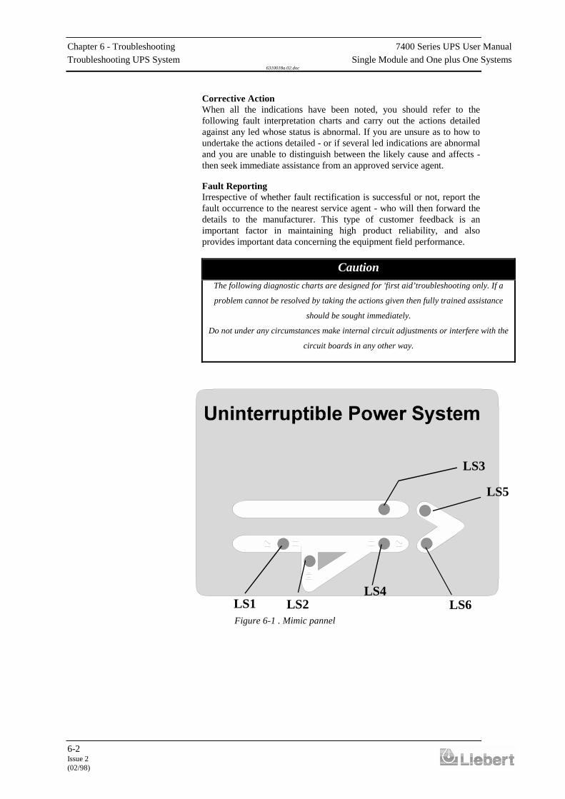
Chapter 6 - Troubleshooting 7400 Series UPS User ManualTroubleshooting UPS System Single Module and One plus One Systems
6310018a.02.doc
6-2Issue 2(02/98)
Corrective ActionWhen all the indications have been noted, you should refer to thefollowing fault interpretation charts and carry out the actions detailedagainst any led whose status is abnormal. If you are unsure as to how toundertake the actions detailed - or if several led indications are abnormaland you are unable to distinguish between the likely cause and affects -then seek immediate assistance from an approved service agent.
Fault ReportingIrrespective of whether fault rectification is successful or not, report thefault occurrence to the nearest service agent - who will then forward thedetails to the manufacturer. This type of customer feedback is animportant factor in maintaining high product reliability, and alsoprovides important data concerning the equipment field performance.
CautionThe following diagnostic charts are designed for 'first aid’troubleshooting only. If a
problem cannot be resolved by taking the actions given then fully trained assistance
should be sought immediately.
Do not under any circumstances make internal circuit adjustments or interfere with the
circuit boards in any other way.
LS3
LS5
LS6LS4
LS2LS1Figure 6-1 . Mimic pannel
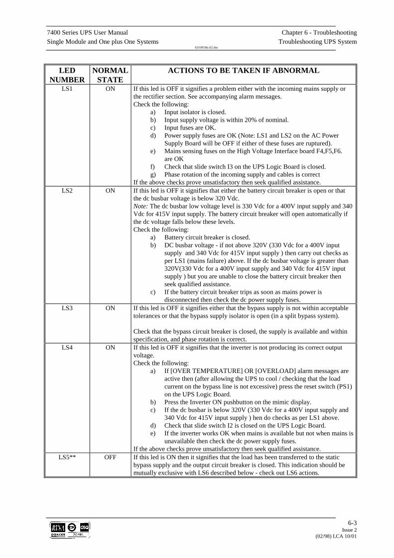
7400 Series UPS User Manual Chapter 6 - TroubleshootingSingle Module and One plus One Systems Troubleshooting UPS System
6310018a.02.doc
6-3Issue 2
(02/98) LCA 10/01
LEDNUMBER
NORMALSTATE
ACTIONS TO BE TAKEN IF ABNORMAL
LS1 ON If this led is OFF it signifies a problem either with the incoming mains supply orthe rectifier section. See accompanying alarm messages.Check the following:
a) Input isolator is closed.b) Input supply voltage is within 20% of nominal.c) Input fuses are OK.d) Power supply fuses are OK (Note: LS1 and LS2 on the AC Power
Supply Board will be OFF if either of these fuses are ruptured).e) Mains sensing fuses on the High Voltage Interface board F4,F5,F6.
are OKf) Check that slide switch I3 on the UPS Logic Board is closed.g) Phase rotation of the incoming supply and cables is correct
If the above checks prove unsatisfactory then seek qualified assistance.LS2 ON If this led is OFF it signifies that either the battery circuit breaker is open or that
the dc busbar voltage is below 320 Vdc.Note: The dc busbar low voltage level is 330 Vdc for a 400V input supply and 340Vdc for 415V input supply. The battery circuit breaker will open automatically ifthe dc voltage falls below these levels.Check the following:
a) Battery circuit breaker is closed.b) DC busbar voltage - if not above 320V (330 Vdc for a 400V input
supply and 340 Vdc for 415V input supply ) then carry out checks asper LS1 (mains failure) above. If the dc busbar voltage is greater than320V(330 Vdc for a 400V input supply and 340 Vdc for 415V inputsupply ) but you are unable to close the battery circuit breaker thenseek qualified assistance.
c) If the battery circuit breaker trips as soon as mains power isdisconnected then check the dc power supply fuses.
LS3 ON If this led is OFF it signifies either that the bypass supply is not within acceptabletolerances or that the bypass supply isolator is open (in a split bypass system).
Check that the bypass circuit breaker is closed, the supply is available and withinspecification, and phase rotation is correct.
LS4 ON If this led is OFF it signifies that the inverter is not producing its correct outputvoltage.Check the following:
a) If [OVER TEMPERATURE] OR [OVERLOAD] alarm messages areactive then (after allowing the UPS to cool / checking that the loadcurrent on the bypass line is not excessive) press the reset switch (PS1)on the UPS Logic Board.
b) Press the Inverter ON pushbutton on the mimic display.c) If the dc busbar is below 320V (330 Vdc for a 400V input supply and
340 Vdc for 415V input supply ) hen do checks as per LS1 above.d) Check that slide switch I2 is closed on the UPS Logic Board.e) If the inverter works OK when mains is available but not when mains is
unavailable then check the dc power supply fuses.If the above checks prove unsatisfactory then seek qualified assistance.
LS5** OFF If this led is ON then it signifies that the load has been transferred to the staticbypass supply and the output circuit breaker is closed. This indication should bemutually exclusive with LS6 described below - check out LS6 actions.

Chapter 6 - Troubleshooting 7400 Series UPS User ManualTroubleshooting UPS System Single Module and One plus One Systems
6310018a.02.doc
6-4Issue 2(02/98)
LS6** ON If LS4 is also OFF then refer to LS4 checks.If LS6 is OFF but LS4 is ON then check the following:
a) Ensure that the output circuit breaker is closed then press the Resetbutton (PS1) on the UPS Logic Board.
b) Ensure that slide switch I1 on the Static Switch Logic Board is in theAUTO position.
If the above checks prove unsatisfactory then seek qualified assistance.
**Note that in a one-plus-one system configured with a redundantmodule, it is possible for one of the two modules to shut down (due to afault for example) without turning on its static switch. In a redundantmodule configuration, a module's static switch is disabled whenever itspartnering module is on line. Therefore in the event of a fault you arelikely to see LS4,5,6 all OFF.

7400 Series UPS User Manual Chapter 6 - TroubleshootingSingle Module and One plus One Systems Troubleshooting UPS System
6310018a.02.doc
6-5Issue 2(02/98)
6.2 Display panel message interpretation
The following table lists the various messages displayed on the operatorpanel together with a description of their interpretation.
DISPLAYMESSAGES
INTERPRETATION
EMERGENCY STOPALARM
This alarm indicates that the UPS was shut down by means of the local or remote (iffitted) emergency stop pushbutton which of course is normally due to operator action- investigate why the emergency stop pushbutton was pressed.If the emergency stop pushbutton was not pressed then check the continuity of theremote emergency stop line (if fitted), and if no remote emergency stop line is fittedthen check that a link is connected between terminals 4 and 5 of the UPS auxiliaryterminal block.
INVERTER OFF ORFAILED ALARM
This alarm is active whenever the inverter is not producing its correct output voltage;either because it has been switched OFF or due to an internal fault.
The alarm will accompany other alarms such as [OVERLOAD], [LOAD ONBYPASS]
OVER TEMPERATUREALARM
Over temperature is sensed by a normally-close thermostat (90°C operating) fitted toeach inverter heat sink. If an over temperature condition arises, the audible alarmwill accompany this message - the inverter stops and load transfers to bypass after 3minutes.
OVERLOADALARM
The inverter overload has an inverse load/time characteristic - i.e. it will accept125% overload for 10 minutes and 150% for 60 seconds. If this characteristic isexceeded then the load transfers to the bypass supply, the inverter stops and theoverload alarm annunciates. The [OVERLOAD] alarm will annunciate at soon as theload exceeds 100% of the UPS rating, and the load will transfer to bypass some timelater -depending on the degree of overload present.
BATTERY CB OPEN orBATTERY FUSE FAILALARM
This is a status indication only. Note that if the UPS if operating with the batterycircuit breaker open and the mains power fails then the UPS output will also failtogether with load power. Also check battery fuses.
OUTPUT CIRCUITBREAKER OPEN ALARM
This is a status alarm. The output isolator must be selected ‘CLOSED’at all timesexcept when operating on the maintenance bypass supply.
RECTIFIER OFF ORFAILED ALARM
This alarm is active whenever the battery charger (rectifier) is not producing itscorrect output voltage; due to either an input supply failure, an internal fault, or anopen input circuit breaker.
UPS ONMAINTENANCE BYPASSWARNING
This is a status warning that the load is being powered through the maintenancebypass line and is unprotected from mains supply abbreviations. Due to the fact thatthe UPS power supplies are fed by the input circuit breaker, this message willdisappear if the input isolator is opened (and bypass isolator opened on a split bypasssystem) while the load is on the maintenance supply.

Chapter 6 - Troubleshooting 7400 Series UPS User ManualTroubleshooting UPS System Single Module and One plus One Systems
6310018a.02.doc
6-6Issue 2(02/98)
INVERTERUNSYNCHRONIZEDWARNING
This warns that the inverter is not synchronised with the bypass supply, which isnormally due to a problem with the bypass supply being outside an acceptablefrequency window. Do not switch OFF the inverter when this alarm is active or theload will experience a 20 msecond power break.
BATTERY ON LOADWARNING
This is a status warning that the battery is discharging. It normally accompanies a[MAINS FAILURE] or [RECTIFIER OFF OR FAILED] message.
MAINS FAILUREWARNING
MAINS FAILURE. Or mains supply out of specified acceptable range. Do not switchOFF the inverter while this indication is active or the load will lose its power.
BYPASS CB OPENALARM
This is a status alarm. The bypass isolator must be closed at all times
LOAD ON BYPASSWARNING
This is a status warning that the load is being powered through the static bypass lineand is unprotected from mains supply aberrations.
Note: The dc busbar low voltage level is 330 Vdc for a 400V inputsupply and 340 Vdc for 415V input supply.The battery circuit breaker will open automatically if the dc voltage fallsbelow these levels.Check the following:b) DC busbar voltage - if not above 320V (330 Vdc for a 400V inputsupply and 340 Vdc for 415V input supply ) then carry out checks as perLS1 (mains failure) above. If the dc busbar voltage is greater than320V(330 Vdc for a 400V input supply and 340 Vdc for 415V inputsupply) but you are unable to close the battery circuit breaker then seekqualified assistance.c) If the dc busbar is below 320V (330 Vdc for a 400V input supply and340 Vdc for 415V input supply) then do checks as per LS1 above.
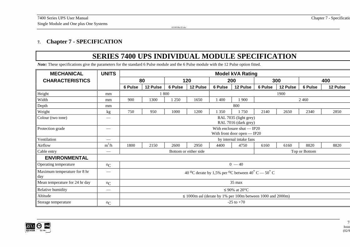
7400 Series UPS User Manual Chapter 7 - SpecificatioSingle Module and One plus One Systems
6310018a.02.doc
7-Issue
(02/9
7. Chapter 7 - SPECIFICATION
SERIES 7400 UPS INDIVIDUAL MODULE SPECIFICATIONNote: These specifications give the parameters for the standard 6 Pulse module and the 6 Pulse module with the 12 Pulse option fitted.
MECHANICAL UNITS Model kVA RatingCHARACTERISTICS 80 120 200 300 400
6 Pulse 12 Pulse 6 Pulse 12 Pulse 6 Pulse 12 Pulse 6 Pulse 12 Pulse 6 Pulse 12 PulseHeight mm 1 800 1900Width mm 900 1300 1 250 1650 1 400 1 900 2 460Depth mm 800Weight kg 750 950 1000 1200 1 350 1 750 2140 2650 2340 2850Colour (two tone) — RAL 7035 (light grey)
RAL 7016 (dark grey)Protection grade — With enclosure shut — IP20
With front door open — IP20Ventilation — by internal intake fansAirflow m3/h 1800 2150 2600 2950 4400 4750 6160 6160 8820 8820Cable entry — Bottom or either side Top or Bottom
ENVIRONMENTALOperating temperature oC 0 — 40
Maximum temperature for 8 hrday
— 40 oC derate by 1,5% per oC between 40° C — 50° C
Mean temperature for 24 hr day oC 35 max
Relative humidity — ≤ 90% at 20°CAltitude ≤ 1000m asl (derate by 1% per 100m between 1000 and 2000m)Storage temperature oC -25 to +70

Chapter 7 - Specification 7400 Series UPS User ManualSingle Module and One plus One Systems
6310018a.02.doc
7-2Issue 2(02/98)
INPUT RATINGS UNITS Model kVA Rating80 120 200 300 400
6 Pulse 12 Pulse 6 Pulse 12 Pulse 6 Pulse 12 Pulse 6 Pulse 12 Pulse 6 Pulse 12 PulsePower consumption at rated load whilefloat charging the battery
kVA 87 84 129 125 216 206 320 309 428 412
Power consumption at rated load whileboost charging the battery
kVA 109 104 161 156 270 257 401 386 534 514
Input current level normal running (380V) A 134 127 202 190 330 313 486 463 646 615Input current level full battery recharge(380V)
A 167 158 251 237 412 390 609 579 808 769
Line voltage V a.c. 380 - 415 3PhPermissible input voltage variation % +10 -15Frequency Hz 50 or 60Permissible input voltage variation % ± 5Power walk-in Progressive over 10 secondsPower factor at rated voltage and load cos Φ 0,8 0,84 0,8 0,84 0,8 0,84 0,8 0,84 0,8 0,84with optional input filter fitted (only 6p) >0,9
SYSTEM DATAEfficiency at 50% load % 92,5 91,3 92,8 91,6 93,0 91,8 94,1 93,1 94,0 93,5Efficiency at 100% load % 92,0 90,2 92,8 90,6 92,8 91,5 93,4 92,5 93,3 92,5Losses at rated load kW 5,8 6,9 7,5 10 12,4 14,9 17,0 19,5 22,2 25,9Losses with battery on boost charge kW 6,1 7,3 8,1 10,6 13,5 15,8 18,5 21 24,4 27,9Losses with no load kW 1,8 1,8 2,5 2,5 4,0 4,0 4,8 6 6 7Acoustic noise at rated load. (1 metre fromthe apparatus according to ISO3746)
dBA 63 63 68 70 69 71 71 73

7400 Series UPS User Manual Chapter 7 - SpecificatioSingle Module and One plus One Systems
6310018a.02.doc
7-Issue
(02/9
OUTPUT RATINGS UNITS Model kVA Rating80 120 200 300 400
6 Pulse 12 Pulse 6 Pulse 12 Pulse 6 Pulse 12 Pulse 6 Pulse 12 Pulse 6 Pulse 12 PulseVoltage V a.c. 380/400/415 (preset on commissioning) 3 Ph NFrequency Hz 50 or 60 (presettable)Power at 0,8pf kVA 80 120 200 300 400Power at 1,0pf kW 64 96 160 240 320Overload ability at 0,8pf 3 ∅
1 ∅
110% for 60 minutes125% for 10 minutes150% for 1 minute
200% for 30 secondsCurrent limiting short circuit (inverter)
150% rated current (3 phase) for220% rated current (1 phase) for
< 5 seconds< 5 seconds
Maximum permissible non linear load % 100 with 3:1 crest factorVoltage stability steady state ± 1%Voltage stability transient state ± 5%Reset time to within ± 1% 20 msFrequency stability synchronised The output will synchronise with the input supply within ±1 Hz of nominal frequency (adjustable to ±2 Hz)Frequency stability unsynchronised ± 0,1% when the input supply frequency is outside the synchronising rangePhase voltage asymmetry balanced load ± 1%Phase voltage dissymmetry 100%unbalanced load
± 2 %
Voltage phase shift with balanced load Angle° 120 ± 1
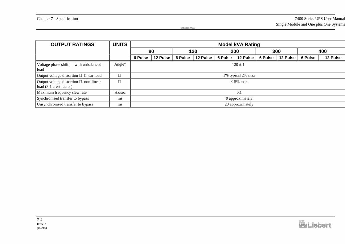
Chapter 7 - Specification 7400 Series UPS User ManualSingle Module and One plus One Systems
6310018a.02.doc
7-4Issue 2(02/98)
OUTPUT RATINGS UNITS Model kVA Rating80 120 200 300 400
6 Pulse 12 Pulse 6 Pulse 12 Pulse 6 Pulse 12 Pulse 6 Pulse 12 Pulse 6 Pulse 12 PulseVoltage phase shift with unbalancedload
Angle° 120 ± 1
Output voltage distortion linear load 1% typical 2% maxOutput voltage distortion non-linearload (3:1 crest factor)
≤ 5% max
Maximum frequency slew rate Hz/sec 0,1Synchronised transfer to bypass ms 0 approximatelyUnsynchronised transfer to bypass ms 20 approximately
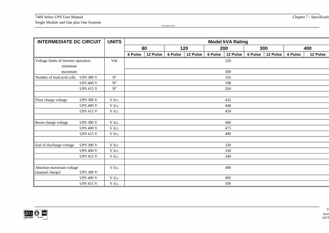
7400 Series UPS User Manual Chapter 7 - SpecificatioSingle Module and One plus One Systems
6310018a.02.doc
7-Issue
(02/9
INTERMEDIATE DC CIRCUIT UNITS Model kVA Rating80 120 200 300 400
6 Pulse 12 Pulse 6 Pulse 12 Pulse 6 Pulse 12 Pulse 6 Pulse 12 Pulse 6 Pulse 12 PulseVoltage limits of inverter operation
minimumVdc 320
maximum 500Number of lead-acid cells UPS 380 V Nº 192
UPS 400 V Nº 198UPS 415 V Nº 204
Float charge voltage UPS 380 V V d.c. 432UPS 400 V V d.c. 446UPS 415 V V d.c. 459
Boost charge voltage UPS 380 V V d.c. 460UPS 400 V V d.c. 475UPS 415 V V d.c. 490
End of discharge voltage UPS 380 V V d.c. 320UPS 400 V V d.c. 330UPS 415 V V d.c. 340
Absolute maximum voltage(manual charge) UPS 380 V
V d.c. 480
UPS 400 V V d.c. 495UPS 415 V V d.c. 500
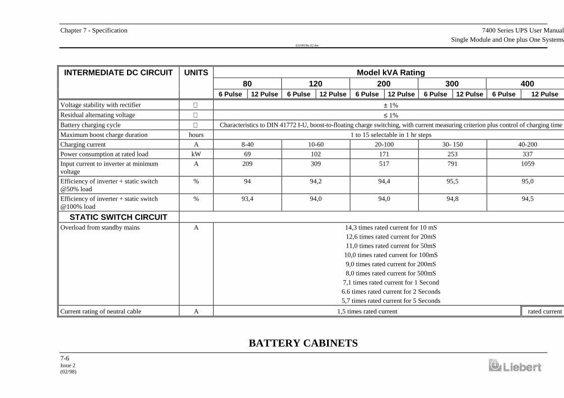
Chapter 7 - Specification 7400 Series UPS User ManualSingle Module and One plus One Systems
6310018a.02.doc
7-6Issue 2(02/98)
INTERMEDIATE DC CIRCUIT UNITS Model kVA Rating80 120 200 300 400
6 Pulse 12 Pulse 6 Pulse 12 Pulse 6 Pulse 12 Pulse 6 Pulse 12 Pulse 6 Pulse 12 PulseVoltage stability with rectifier ± 1%Residual alternating voltage ≤ 1%Battery charging cycle Characteristics to DIN 41772 I-U, boost-to-floating charge switching, with current measuring criterion plus control of charging timeMaximum boost charge duration hours 1 to 15 selectable in 1 hr stepsCharging current A 8-40 10-60 20-100 30- 150 40-200Power consumption at rated load kW 69 102 171 253 337Input current to inverter at minimumvoltage
A 209 309 517 791 1059
Efficiency of inverter + static switch@50% load
% 94 94,2 94,4 95,5 95,0
Efficiency of inverter + static switch@100% load
% 93,4 94,0 94,0 94,8 94,5
STATIC SWITCH CIRCUITOverload from standby mains A 14,3 times rated current for 10 mS
12,6 times rated current for 20mS11,0 times rated current for 50mS
10,0 times rated current for 100mS9,0 times rated current for 200mS8,0 times rated current for 500mS
7,1 times rated current for 1 Second6.6 times rated current for 2 Seconds5,7 times rated current for 5 Seconds
Current rating of neutral cable A 1,5 times rated current rated current
BATTERY CABINETS

7400 Series UPS User Manual Chapter 7 - SpecificatioSingle Module and One plus One Systems
6310018a.02.doc
7-Issue
(02/9
MECHANICALCHARACTERISTICS
UNITS 860 mm Cabinet
Dimensions (W X D X H) mm 860 X 800 X 1800Weight (without batteries) kg 140Battery circuit breaker size Amps 250Ventilation NaturalLifting Top (via eyes) or bottom (trans-pallet entry)
BATTERY CIRCUIT BREAKERBOX
N° ofPoles
Suitable for UPS size (kVA)
250 A 3 80 - 120400 A 4 120630 A 4 200800 A 4 3001000 A 4 400
Undervoltage trip coil rating all units 110Vdc (6,7 9,2 kOhms)Auxiliary contacts (for signalling) all units 1 set changeover
