800 series lanterns - carmanah · revised september 2017, 69928_8xx_usermanual_revd summary of...
TRANSCRIPT
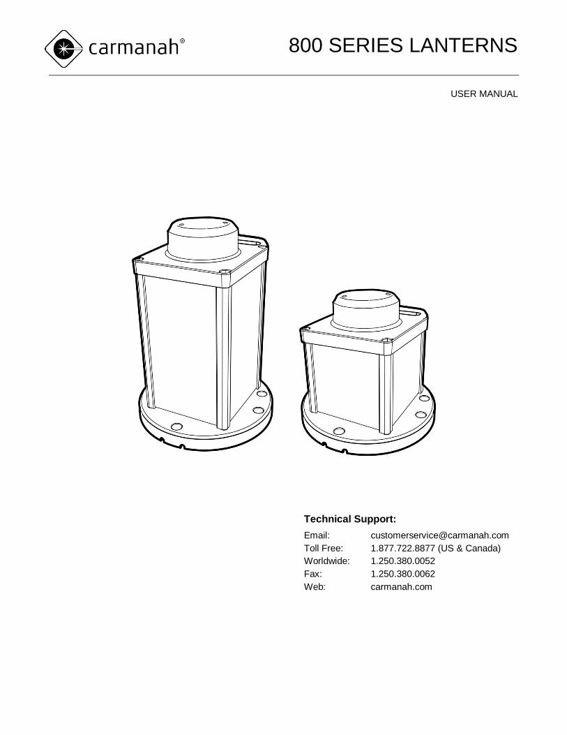
800 SERIES LANTERNS
USER MANUAL
Technical Support:
Email: [email protected]
Toll Free: 1.877.722.8877 (US & Canada)
Worldwide: 1.250.380.0052
Fax: 1.250.380.0062
Web: carmanah.com
800 SERIES LANTERNS
2 © 2017, Carmanah Technologies Corporation. Revised September 2017, 69928_8XX_UserManual_RevD
Warnings & Precautions
The following symbols indicate important safety
warnings and precautions throughout this manual.
They are defined as follows:
WARNING indicates that serious bodily
harm or death may result from failure to
adhere to the precautions.
CAUTION indicates that damage to
equipment may result if the instructions
are not followed.
NOTE suggests optimal conditions
under which the equipment will operate
effectively and safely, or provides
additional information to the reader.
Regulatory Information
This Class [B] digital apparatus complies with
Canadian ICES-003.
Cet appareil numérique de la classe [B] est
conforme à la norme NMB-003 du Canada.
Changes or modifications not expressly
approved by the party responsible for
compliance could void the user’s
authority to operate the equipment.
Installation work must be done by a
qualified person(s) in accordance with
all applicable local codes and standards.
Equipment shall be positioned outside
the 5m vicinity of a compass as per
ISO 694.
Safety and Usage Precautions
The lantern's Battery Pack contains
lead, lead compounds, and other
compounds known to the State of
California to cause cancer and
reproductive harm. Please handle with
care and wash your hands thoroughly
after handling the Battery Pack.
Charge your lantern's Battery Pack
periodically. Permanent damage and
reduced capacity will result if the Battery
Pack is not correctly maintained. Refer
to page 222 for details.
Lanterns that have been stored may require a top-up
charge before they are put into service. The most
accurate Battery Pack status reading is obtained
when the lantern has been in a dark location and in
Off mode for at least 24 hours.
Warranty Disclaimer
This manual will familiarize you with the
features and operation standards of
Carmanah’s 800 Series lantern. Failure
to comply with the use, storage,
maintenance, installation or placement
instructions detailed in this manual could
void the applicable user warranty.
8xx USER MANUAL
TABLE OF CONTENTS
3 © 2017, Carmanah Technologies Corporation. Revised September 2017, 69928_8XX_UserManual_RevD
Table of Contents
Warnings & Precautions .................................... 2 Regulatory Information....................................... 2 Safety and Usage Precautions ........................... 2 Warranty Disclaimer .......................................... 2 Table of Contents .............................................. 3
Introduction .................................................... 4
Applications ....................................................... 4 Range ............................................................... 4 Common Features and Functionality .................. 4
Parts Description ........................................... 5
Programming the Lantern ............................. 6
Preparing the Lantern for Installation ................. 6 Viewing Lantern Settings ................................... 6 Summary of Lantern States and Statuses .......... 7 Using the Infrared (IR) Programmer ..................11 Turning the Lantern On or Off ...........................12 Setting the Flash Character ..............................13 Setting Effective Intensity ..................................13
Setting an Intensity to Comply with Obstruction
Lighting Standards........................................13 For all other applications: ..............................14
Activating/De-activating Automatic Light Control
(ALC)................................................................14 Setting the Calendar Function ...........................15
To toggle the Calendar setting on or off: .......15 To set the date that the lantern will enter dated
shutdown: .....................................................15 To set the date the lantern will reactivate: .....15
Editing the Lantern Date and Time (Non-GPS
Units Only) .......................................................16 To edit the lantern date: ................................16 To edit the lantern time: ................................16
Setting Day-to-Night Transition Level ................17 Setting Night-to-Day Transition Level ................17 Enable/Disable Tap-to-Activate LED Display
Option ..............................................................18 Viewing Firmware Version ................................18 Enabling Telemetry ...........................................18 Setting the GPS Synchronization Function (GPS-
equipped Lanterns Only) ...................................19 GPS Status (GPS-equipped Lanterns Only) ......19
Installing a Lantern ..................................... 20
Choosing a Suitable Location ........................... 20 Adequate Sunlight ....................................... 20 Ambient Temperature .................................. 20
Securing the Lantern ........................................ 20 Installing the Bird Deterrent .............................. 21
Charging the Lantern .................................. 22
Sunlight ....................................................... 22 External Power Source ................................ 22 Charge Indicator .......................................... 22
Charging via an External Power Source (Quick
Access Charge Port) ........................................ 22 Determining Battery State of Charge ................ 23 Changing the Battery ....................................... 24 Changing the Battery (12V) .............................. 26
Preparing the Lantern for Storage ............. 29
Storage Maintenance/Duration ......................... 29
Warranty and Customer Service ................ 30
Warranty .......................................................... 30 Additional Products .......................................... 30 Customer Service ............................................ 30 Appendix A: Flash Characters .................... 31 Appendix B: Troubleshooting ...................... 40

800 SERIES USER MANUAL
INTRODUCTION
4 © 2017, Carmanah Technologies Corporation. Revised September 2017, 69928_8XX_UserManual_RevD
Introduction
Applications
The 800 Series lantern has the following
applications:
Fixed and floating aids to navigation
Port, marina and dock lighting
Offshore platform marking
Aquaculture
Tower & crane marking
Hazard marking and way-finding
Range
The 800 Series Lantern is visible from up to
approximately 10 nautical miles (18.5 km) at night
depending on the installation location and selected
flash setting.
For a detailed understanding of range and intensity
capabilities at your installation location, visit our
simulation tool at carmanah.com/selector.
Common Features and
Functionality
The 800 Series lantern is a self-contained, high-
performance, solar powered light with the following
features:
Easily visible, “tap-to-activate” digital LED
display
Latest generation, high-efficiency LEDs and
optics
Simplified installation & setup. No
“transitioning” required prior to installation or
storage.
Rugged polycarbonate and aluminum
enclosure for maximum durability in a
lightweight, economical package
Calendar function available for automatically
de-activating lights during off-season
periods
Optional GPS synchronization for setting
any number of lanterns and other Carmanah
GPS-equipped lanterns to flash in unison
Optional secure satellite monitoring and
status reporting (M800 lanterns only)
800 SERIES USER MANUAL
PROGRAMMING
5 © 2017, Carmanah Technologies Corporation. Revised September 2017, 69928_8XX_UserManual_RevD
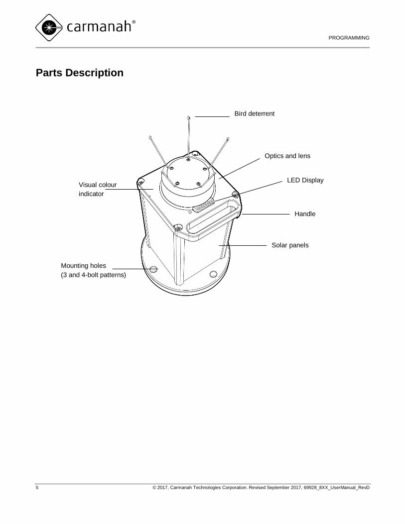
Parts Description
Solar panels
Mounting holes
(3 and 4-bolt patterns)
Bird deterrent
LED Display Visual colour
indicator
Optics and lens
Handle
800 SERIES USER MANUAL
PROGRAMMING
6 © 2017, Carmanah Technologies Corporation. Revised September 2017, 69928_8XX_UserManual_RevD
Programming the Lantern
Please thoroughly read these
instructions before proceeding with
the installation.
Preparing the Lantern for
Installation
The 800 Series lantern has been designed with a
simplified user experience in mind. Lights are ready
for use on shipment and do not have to be
“transitioned” from day to night before making
changes to settings.
Pre-Programmed Lanterns
If Carmanah or a Carmanah authorized distributor
has programmed the lantern prior to you receiving it,
it is ready to install. When the lantern is removed
from the box and exposed to light, it will begin
normal operation, activating with the next day-to-
night transition. Prior to field deployment, verify that
the lantern’s pre-programmed settings match
your requirements using the top-mounted LED
display. Refer to the following section on “Viewing
Lantern Settings” for details. If you have been
supplied with an IR programmer, you may modify
lantern settings prior to installation if desired.
Non-Programmed Lanterns
If you have not requested a pre-programmed
lantern, you will need to verify the lantern settings
(intensity, flash pattern, calendar function & etc.) and
make any required modifications using a Carmanah
IR programmer. Refer to the following sections on
“Viewing Lantern Settings” and “Using the Infrared
(IR) Programmer” for details. If you require a
Carmanah IR programmer, please contact
Carmanah or your authorized distributor.
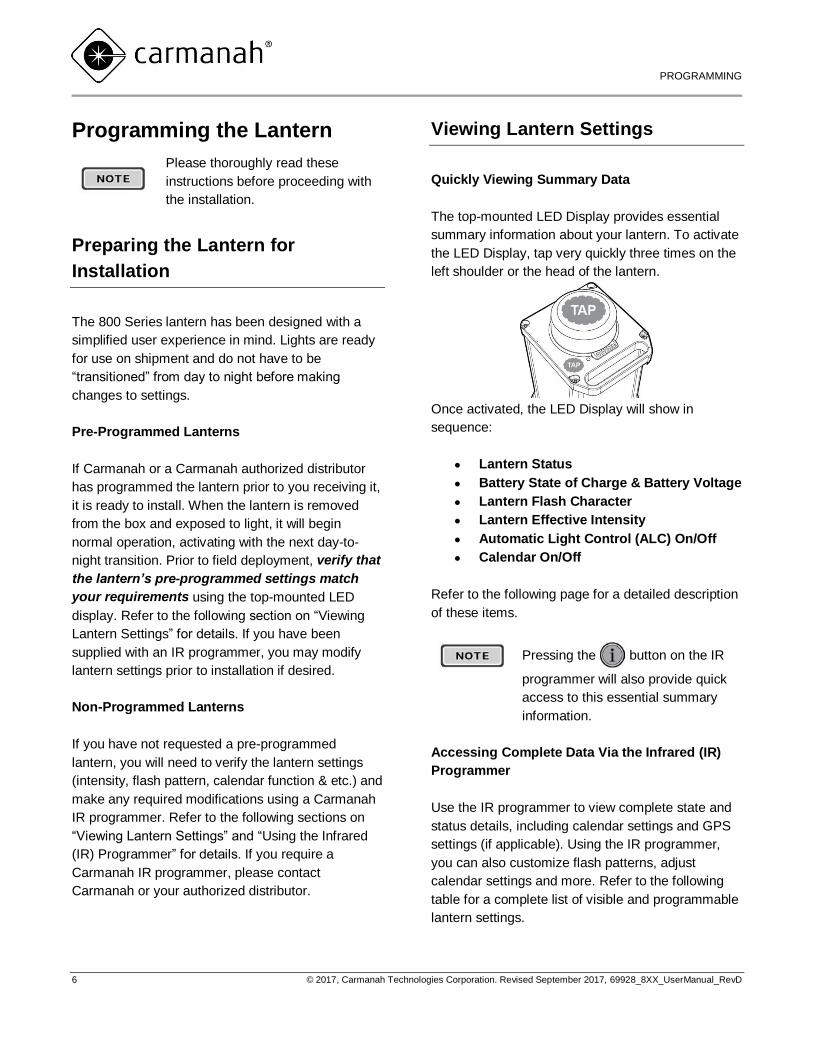
Viewing Lantern Settings
Quickly Viewing Summary Data
The top-mounted LED Display provides essential
summary information about your lantern. To activate
the LED Display, tap very quickly three times on the
left shoulder or the head of the lantern.
Once activated, the LED Display will show in
sequence:
Lantern Status
Battery State of Charge & Battery Voltage
Lantern Flash Character
Lantern Effective Intensity
Automatic Light Control (ALC) On/Off
Calendar On/Off
Refer to the following page for a detailed description
of these items.
Pressing the button on the IR
programmer will also provide quick
access to this essential summary
information.
Accessing Complete Data Via the Infrared (IR)
Programmer
Use the IR programmer to view complete state and
status details, including calendar settings and GPS
settings (if applicable). Using the IR programmer,
you can also customize flash patterns, adjust
calendar settings and more. Refer to the following
table for a complete list of visible and programmable
lantern settings.
800 SERIES USER MANUAL
PROGRAMMING
7 © 2017, Carmanah Technologies Corporation. Revised September 2017, 69928_8XX_UserManual_RevD
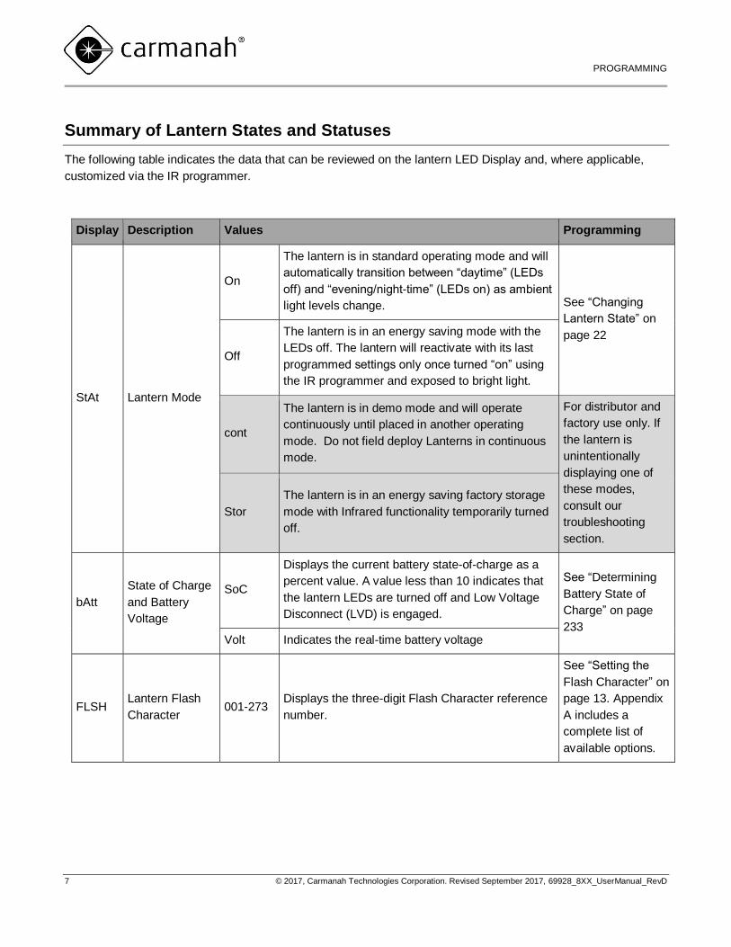
Summary of Lantern States and Statuses
The following table indicates the data that can be reviewed on the lantern LED Display and, where applicable,
customized via the IR programmer.
Display Description Values Programming
StAt Lantern Mode
On
The lantern is in standard operating mode and will
automatically transition between “daytime” (LEDs
off) and “evening/night-time” (LEDs on) as ambient
light levels change. See “Changing
Lantern State” on
page 22
Off
The lantern is in an energy saving mode with the
LEDs off. The lantern will reactivate with its last
programmed settings only once turned “on” using
the IR programmer and exposed to bright light.
cont
The lantern is in demo mode and will operate
continuously until placed in another operating
mode. Do not field deploy Lanterns in continuous
mode.
For distributor and
factory use only. If
the lantern is
unintentionally
displaying one of
these modes,
consult our
troubleshooting
section.
Stor
The lantern is in an energy saving factory storage
mode with Infrared functionality temporarily turned
off.
bAtt
State of Charge
and Battery
Voltage
SoC
Displays the current battery state-of-charge as a
percent value. A value less than 10 indicates that
the lantern LEDs are turned off and Low Voltage
Disconnect (LVD) is engaged.
See “Determining
Battery State of
Charge” on page
233 Volt Indicates the real-time battery voltage
FLSH Lantern Flash
Character 001-273
Displays the three-digit Flash Character reference
number.
See “Setting the
Flash Character” on
page 13. Appendix
A includes a
complete list of
available options.
800 SERIES USER MANUAL
PROGRAMMING
8 © 2017, Carmanah Technologies Corporation. Revised September 2017, 69928_8XX_UserManual_RevD
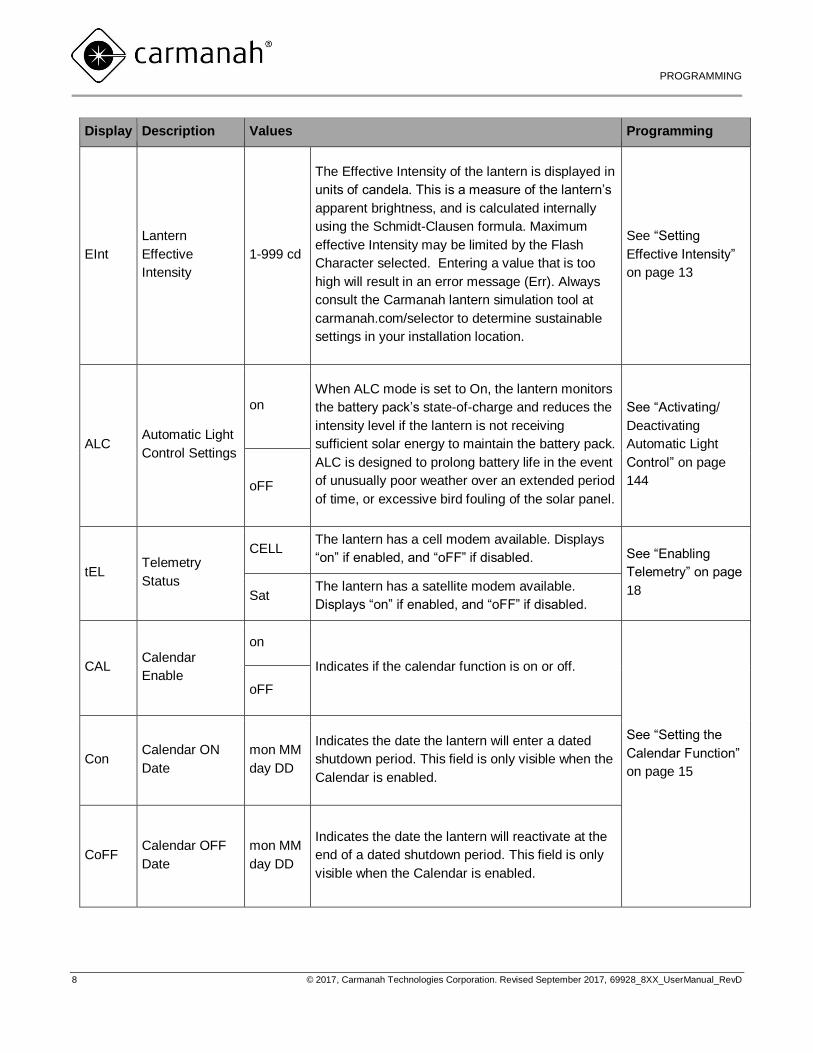
Display Description Values Programming
EInt
Lantern
Effective
Intensity
1-999 cd
The Effective Intensity of the lantern is displayed in
units of candela. This is a measure of the lantern’s
apparent brightness, and is calculated internally
using the Schmidt-Clausen formula. Maximum
effective Intensity may be limited by the Flash
Character selected. Entering a value that is too
high will result in an error message (Err). Always
consult the Carmanah lantern simulation tool at
carmanah.com/selector to determine sustainable
settings in your installation location.
See “Setting
Effective Intensity”
on page 13
ALC Automatic Light
Control Settings
on
When ALC mode is set to On, the lantern monitors
the battery pack’s state-of-charge and reduces the
intensity level if the lantern is not receiving
sufficient solar energy to maintain the battery pack.
ALC is designed to prolong battery life in the event
of unusually poor weather over an extended period
of time, or excessive bird fouling of the solar panel.
See “Activating/
Deactivating
Automatic Light
Control” on page
144 oFF
tEL Telemetry
Status
CELL The lantern has a cell modem available. Displays
“on” if enabled, and “oFF” if disabled. See “Enabling
Telemetry” on page
18 Sat The lantern has a satellite modem available.
Displays “on” if enabled, and “oFF” if disabled.
CAL Calendar
Enable
on
Indicates if the calendar function is on or off.
See “Setting the
Calendar Function”
on page 15
oFF
Con Calendar ON
Date
mon MM
day DD
Indicates the date the lantern will enter a dated
shutdown period. This field is only visible when the
Calendar is enabled.
CoFF Calendar OFF
Date
mon MM
day DD
Indicates the date the lantern will reactivate at the
end of a dated shutdown period. This field is only
visible when the Calendar is enabled.
800 SERIES USER MANUAL
PROGRAMMING
9 © 2017, Carmanah Technologies Corporation. Revised September 2017, 69928_8XX_UserManual_RevD
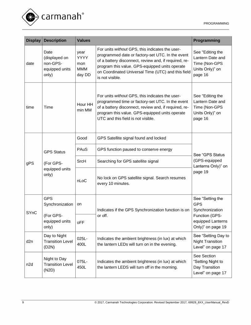
Display Description Values Programming
date
Date
(displayed on
non-GPS-
equipped units
only)
year
YYYY
mon
MMM
day DD
For units without GPS, this indicates the user-
programmed date or factory-set UTC. In the event
of a battery disconnect, review and, if required, re-
program this value. GPS-equipped units operate
on Coordinated Universal Time (UTC) and this field
is not visible.
See "Editing the
Lantern Date and
Time (Non-GPS
Units Only)” on
page 16
time Time Hour HH
min MM
For units without GPS, this indicates the user-
programmed time or factory-set UTC. In the event
of a battery disconnect, review and, if required, re-
program this value. GPS-equipped units operate
UTC and this field is not visible.
See "Editing the
Lantern Date and
Time (Non-GPS
Units Only)” on
page 16
gPS
GPS Status
(For GPS-
equipped units
only)
Good GPS Satellite signal found and locked
See “GPS Status
(GPS-equipped
Lanterns Only)” on
page 19
PAuS GPS function paused to conserve energy
SrcH Searching for GPS satellite signal
nLoC No lock on GPS satellite signal. Search resumes
every 10 minutes.
SYnC
GPS
Synchronization
(For GPS-
equipped units
only)
on
Indicates if the GPS Synchronization function is on
or off.
See “Setting the
GPS
Synchronization
Function (GPS-
equipped Lanterns
Only)” on page 19 oFF
d2n
Day to Night
Transition Level
(D2N)
025L-
400L
Indicates the ambient brightness (in lux) at which
the lantern LEDs will turn on in the evening.
See “Setting Day to
Night Transition
Level” on page 17
n2d
Night to Day
Transition Level
(N2D)
075L-
450L
Indicates the ambient brightness (in lux) at which
the lantern LEDS will turn off in the morning.
See Section
“Setting Night to
Day Transition
Level” on page 17
800 SERIES USER MANUAL
PROGRAMMING
10 © 2017, Carmanah Technologies Corporation. Revised September 2017, 69928_8XX_UserManual_RevD
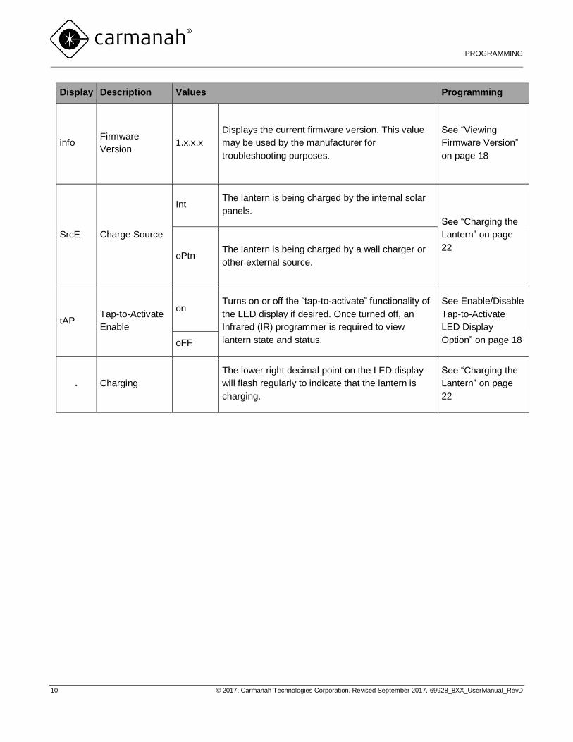
Display Description Values Programming
info Firmware
Version 1.x.x.x
Displays the current firmware version. This value
may be used by the manufacturer for
troubleshooting purposes.
See “Viewing
Firmware Version”
on page 18
SrcE Charge Source
Int The lantern is being charged by the internal solar
panels. See “Charging the
Lantern” on page
22 oPtn
The lantern is being charged by a wall charger or
other external source.
tAP Tap-to-Activate
Enable
on Turns on or off the “tap-to-activate” functionality of
the LED display if desired. Once turned off, an
Infrared (IR) programmer is required to view
lantern state and status.
See Enable/Disable
Tap-to-Activate
LED Display
Option” on page 18 oFF
. Charging
The lower right decimal point on the LED display
will flash regularly to indicate that the lantern is
charging.
See “Charging the
Lantern” on page
22
800 SERIES USER MANUAL
PROGRAMMING
11 © 2017, Carmanah Technologies Corporation. Revised September 2017, 69928_8XX_UserManual_RevD
Using the Infrared (IR)
Programmer
All functions of the 800 Series lantern are controlled
by the IR programmer.
Important User Notes
The IR programmer uses one
CR2025 battery (shipped with unit).
Remove the battery tab from the
back of the IR programmer on first
use.
Keep a minimum distance of 6” (15
cm) between the IR programmer
and the lantern.
The Lantern must be in “on” mode
to change settings using the IR
programmer. If a Lantern is in “off”
mode, you may review settings
using the key, but you will not
be able to scroll through detailed
information or program the lantern.
The IR programmer includes the following keys:
The power key awakens the infrared
sensor inside the lantern and allows
the unit to accept programming
commands.
To conserve power, the 800 Series
lantern searches for an Infrared
signal on a 0.5 second cycle. You
may need to press the power key
multiple times to establish a
connection. Typically, three steady
button presses will be sufficient;
however, you may need to make
more or fewer connection attempts
to coincide with the lantern signal.
The
lantern LEDs will flash to confirm
that a connection has been made.
Once a connection has been made,
all IR commands will be received
and confirmed with a flash. If no IR
signals are received within 60
seconds, the IR receiver will switch
back to power saving mode.
The information key provides quick
access to Lantern Status, Battery
State of Charge & Battery Voltage,
Lantern Flash Character, Lantern
Effective Intensity, Automatic Light
Control (ALC) setting, and Calendar
On/Off.
Use the up/down arrow keys to
scroll easily through the LED Display
values.
The left/right arrow keys are used to
navigate away from a selected menu
item, or to move between digits
when programming a setting.
Use the number keys to directly
enter numeric values.
The (A) key allows jumps directly to
the Flash Character menu to view or
edit Flash Character settings.
The (B) key jumps directly to the
Lantern Effective Intensity menu to
view or edit Effective Intensity.
800 SERIES USER MANUAL
PROGRAMMING
12 © 2017, Carmanah Technologies Corporation. Revised September 2017, 69928_8XX_UserManual_RevD
The set button unlocks and locks
settings. Press this button to change
a displayed value (editable settings
only) and to lock in an updated
value. When a new value is locked,
the lantern LEDs and the LED
display will flash three times to
confirm that the new settings have
been registered and are active. If a
value is entered that is outside of the
lantern’s acceptable parameters
then “Err” (error) is displayed, the
LEDs will flash two times, and the
lantern will revert to the previous
setting.
Turning the Lantern On or Off
The 800 Series lantern can be switched into the
following two basic operating modes:
On: The lantern is in standard operating
mode and will automatically transition
between “daytime” (LEDs off) and
“evening/night-time” (LEDs on) as ambient
light levels change.
Off: The lantern is in an energy saving
mode with the LEDs off. The lantern will
reactivate with its last programmed settings
only once turned “on” using the IR
programmer and exposed to bright light.
An additional “Continuous” mode is also available on
distributor demo units. Contact
[email protected] for the activation
code for this mode. To exit continuous mode select
On or Off in the Stat menu.
To turn the lantern on or off:
1. If you have not already done so,
establish a connection to the lantern.
2. The lantern LEDs will flash to confirm
the lantern is ready to receive
commands.
3. Press and hold the power button for
approximately five seconds until the
LED display changes to show “stAt
On” or “byE”.
800 SERIES USER MANUAL
PROGRAMMING
13 © 2017, Carmanah Technologies Corporation. Revised September 2017, 69928_8XX_UserManual_RevD
Setting the Flash Character
A complete list of available Flash Characters is
provided in Appendix A.
1. If you have not already done so,
establish a connection to the
lantern.
2. The lantern LEDs will flash to
confirm the lantern is ready to
receive commands.
or
3. Navigate to the FLSH menu or
press the (A) button to jump directly
to this function
4. Unlock the existing setting
5. Use the number keys to direct enter
the desired Flash Character (see
Appendix A).
6. Lock the new setting
7. The lantern LEDs will flash to
confirm that the new setting has
been locked.
The 800 Series has intelligent
settings to prevent the lantern from
operating with certain Flash
Character and Effective Intensity
combinations. Effective Intensity
may be automatically lowered when
you change Flash Characters.
ALWAYS review Effective Intensity
after changing Flash Characters.
Review the online simulator at
carmanah.com/selector to find
Flash Character and Effective
Intensity combinations that are
sustainable in your installation
location.
Setting Effective Intensity
The Effective Intensity of the lantern is a measure of
its apparent brightness in candela. It takes into
account the reduction from peak intensity caused by
the Schmidt Clausen factor.
Setting an Intensity to Comply with
Obstruction Lighting Standards
Users of the OL800 Series Obstruction Lights may
wish to program the light to meet a specific
Obstruction specification.
If you have not already done so,
establish a connection to the lantern.
The lantern LEDs will flash to confirm the
lantern is ready to receive commands.
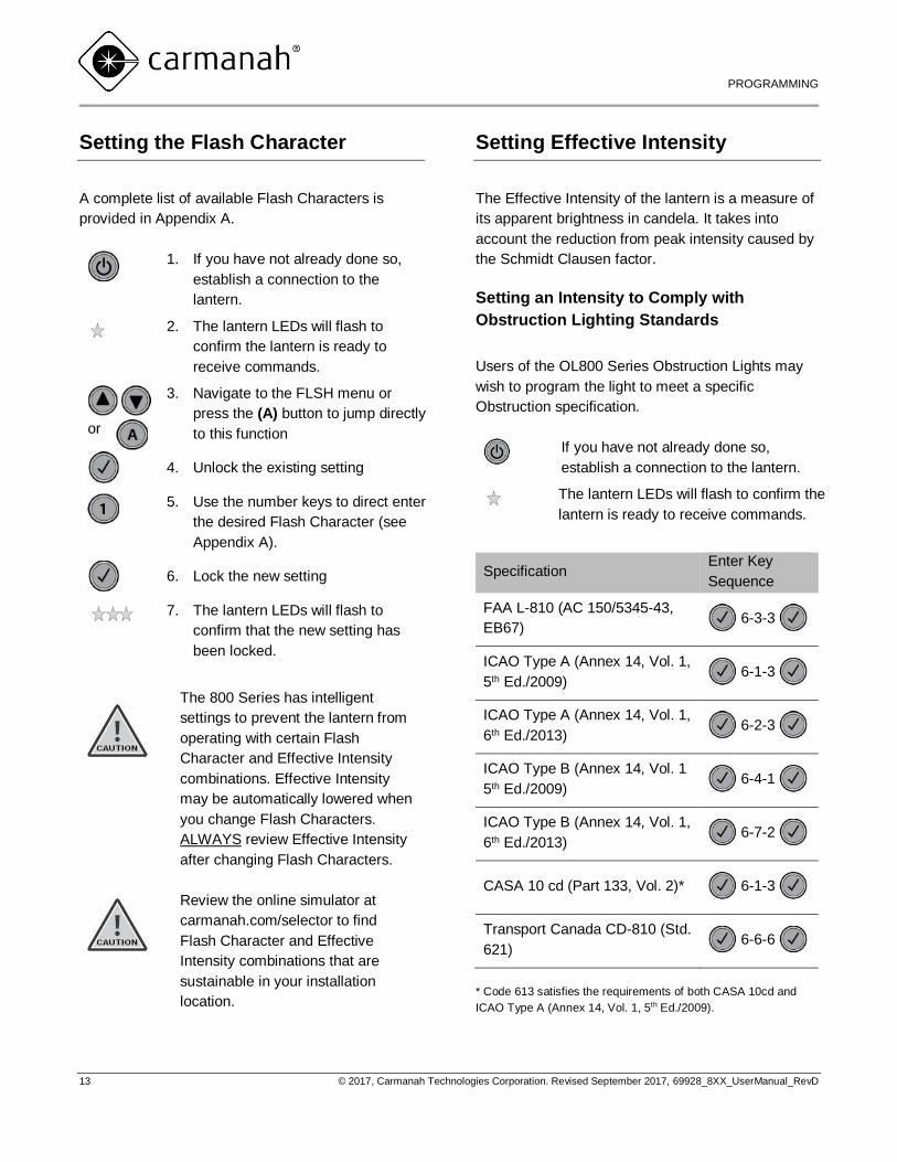
Specification Enter Key
Sequence
FAA L-810 (AC 150/5345-43,
EB67) 6-3-3
ICAO Type A (Annex 14, Vol. 1,
5th Ed./2009) 6-1-3
ICAO Type A (Annex 14, Vol. 1,
6th Ed./2013) 6-2-3
ICAO Type B (Annex 14, Vol. 1
5th Ed./2009) 6-4-1
ICAO Type B (Annex 14, Vol. 1,
6th Ed./2013) 6-7-2
CASA 10 cd (Part 133, Vol. 2)* 6-1-3
Transport Canada CD-810 (Std.
621) 6-6-6
* Code 613 satisfies the requirements of both CASA 10cd and
ICAO Type A (Annex 14, Vol. 1, 5th Ed./2009).

800 SERIES USER MANUAL
PROGRAMMING
14 © 2017, Carmanah Technologies Corporation. Revised September 2017, 69928_8XX_UserManual_RevD
For all other applications:
1. If you have not already done so,
establish a connection to the lantern.
2. The lantern LEDs will flash to confirm
the lantern is ready to receive
commands.
or
3. Navigate to the EInt menu or press
the (B) button to jump directly to this
function
4. Unlock the existing setting
5. Use the number keys to direct enter
the desired Effective Intensity.
6. Lock the new setting
7. The lantern LEDs will flash to confirm
that the new setting has been locked.
The 800 Series has intelligent
settings to prevent the lantern from
running with certain Flash
Character and Effective Intensity
combinations. You may receive an
error (Err) message if you are
attempting to enter a value that is
not compatible with your
programmed Flash Character.
Choose a lower value or modify
your Flash Character to resolve
this issue.
To protect battery life, always
consult the online simulator at
carmanah.com/selector to find the
maximum sustainable intensity for
your installation location.
Activating/De-activating Automatic
Light Control (ALC)
When ALC mode is set to “on”, the lantern monitors
the battery pack’s state of health and reduces the
intensity level if there is insufficient solar energy to
maintain the battery pack.
1. If you have not already done so,
establish a connection to the
lantern.
2. The lantern LEDs will flash to
confirm the lantern is ready to
receive commands.
3. Navigate to the ALC menu
4. Unlock the existing setting
5. Toggle between “on” and “off”
6. Lock the new setting
7. The lantern LEDs will flash to
confirm that the new setting has
been locked.
To quickly change ALC settings,
you may direct enter one of the
following quick access codes:
8-0-1 (to activate)
8-0-0 (to deactivate)
When ALC intervenes, the LEDs
brightness is reduced. Set the ALC
to off if your application demands
that the lantern meets specific
intensity requirements at all times.
800 SERIES USER MANUAL
PROGRAMMING
15 © 2017, Carmanah Technologies Corporation. Revised September 2017, 69928_8XX_UserManual_RevD
Setting the Calendar Function
The Calendar Function allows you to specify a dated
shutdown if desired.
GPS-enabled lanterns will be
synched to Coordinated Universal
Time (UTC). For units without
GPS, check the LED Display for
the current date and time and, if
required, update the date setting
prior to programming the calendar
function.
To toggle the Calendar setting on or off:
4. If you have not already done so,
establish a connection to the lantern.
5. The lantern LEDs will flash to confirm
the lantern is ready to receive
commands.
6. Navigate to the CAL menu.
7. Unlock the existing setting
8. Toggle between “on” and “off
9. Lock the new setting
10. The lantern LEDs will flash to confirm
that the new setting has been locked.
To set the date that the lantern will enter
dated shutdown:
Confirm that the Calendar is turned “on”.
1. Navigate to the Con menu
2. Scroll to the Month value (ΠΠon)
3. Unlock the existing setting
4. Use the number keys to enter the
month when dated shutdown will
begin.
5. Lock the new setting
6. Scroll to the day value (dAY)
7. Use the number keys to enter the
specific day of the month when
dated shutdown will begin.
8. Lock the new setting
9. The lantern LEDs will flash to
confirm that the new setting has
been locked.
To set the date the lantern will reactivate:
Confirm that the Calendar is turned “on”.
1. Navigate to the CoFF menu
2. Scroll to the Month value (ΠΠon)
3. Unlock the existing setting
4. Use the number keys to enter the
month when dated shutdown will
end.
5. Lock the new setting
6. Scroll to the day value (dAY)
7. Use the number keys to enter the
specific day of the month when
dated shutdown will end.
8. Lock the new setting
9. The lantern LEDs will flash to
confirm your change.
800 SERIES USER MANUAL
PROGRAMMING
16 © 2017, Carmanah Technologies Corporation. Revised September 2017, 69928_8XX_UserManual_RevD
Editing the Lantern Date and Time
(Non-GPS Units Only)
Lantern Date and Time are used for data logging
and for controlling the calendar function. The 800
Series lantern (without GPS) has an internal clock
which it uses for logging activity. The lantern will be
factory programmed in Coordinated Universal Time
(UTC). You may re-program the lantern to local date
and time if desired. In the event that the lantern
battery pack is disconnected, verify the date settings
and reset if required.
GPS-equipped units will be
synchronized to Coordinated
Universal Time (UTC). The
date/time settings on GPS-
equipped units cannot be modified.
To edit the lantern date:
1. If you have not already done so,
establish a connection to the
lantern.
2. The lantern LEDs will flash to
confirm the lantern is ready to
receive commands.
3. Navigate to the date menu
4. Scroll to the Month value (ΠΠon)
5. Unlock the existing setting
6. Use the number keys to enter the
current month.
7. Lock the new setting
8. Scroll to the Day value (dAY)
9. Use the number keys to enter the
current day.
10. Lock the new setting
The lantern LEDs will flash to confirm
that the new setting has been locked.
To edit the lantern time:
1. If you have not already done so,
establish a connection to the
lantern.
2. The lantern LEDs will flash to
confirm the lantern is ready to
receive commands.
3. Navigate to the Time menu
4. Scroll to the hour value (HH)
5. Unlock the existing setting
6. Use the number keys to enter the
current hour (24-hour clock).
7. Lock the new setting
8. Scroll to the minute value (MM)
9. Use the number keys to enter the
current minute
10. Lock the new setting
11. The lantern LEDs will flash to
confirm that the new setting has
been locked.
800 SERIES USER MANUAL
PROGRAMMING
17 © 2017, Carmanah Technologies Corporation. Revised September 2017, 69928_8XX_UserManual_RevD
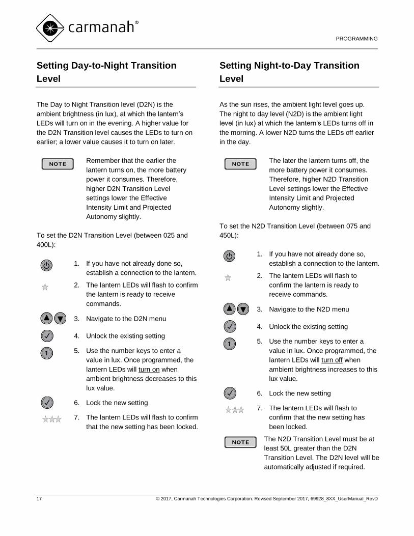
Setting Day-to-Night Transition
Level
The Day to Night Transition level (D2N) is the
ambient brightness (in lux), at which the lantern’s
LEDs will turn on in the evening. A higher value for
the D2N Transition level causes the LEDs to turn on
earlier; a lower value causes it to turn on later.
Remember that the earlier the
lantern turns on, the more battery
power it consumes. Therefore,
higher D2N Transition Level
settings lower the Effective
Intensity Limit and Projected
Autonomy slightly.
To set the D2N Transition Level (between 025 and
400L):
1. If you have not already done so,
establish a connection to the lantern.
2. The lantern LEDs will flash to confirm
the lantern is ready to receive
commands.
3. Navigate to the D2N menu
4. Unlock the existing setting
5. Use the number keys to enter a
value in lux. Once programmed, the
lantern LEDs will turn on when
ambient brightness decreases to this
lux value.
6. Lock the new setting
7. The lantern LEDs will flash to confirm
that the new setting has been locked.
Setting Night-to-Day Transition
Level
As the sun rises, the ambient light level goes up.
The night to day level (N2D) is the ambient light
level (in lux) at which the lantern’s LEDs turns off in
the morning. A lower N2D turns the LEDs off earlier
in the day.
The later the lantern turns off, the
more battery power it consumes.
Therefore, higher N2D Transition
Level settings lower the Effective
Intensity Limit and Projected
Autonomy slightly.
To set the N2D Transition Level (between 075 and
450L):
1. If you have not already done so,
establish a connection to the lantern.
2. The lantern LEDs will flash to
confirm the lantern is ready to
receive commands.
3. Navigate to the N2D menu
4. Unlock the existing setting
5. Use the number keys to enter a
value in lux. Once programmed, the
lantern LEDs will turn off when
ambient brightness increases to this
lux value.
6. Lock the new setting
7. The lantern LEDs will flash to
confirm that the new setting has
been locked.
The N2D Transition Level must be at
least 50L greater than the D2N
Transition Level. The D2N level will be
automatically adjusted if required.
800 SERIES USER MANUAL
PROGRAMMING
18 © 2017, Carmanah Technologies Corporation. Revised September 2017, 69928_8XX_UserManual_RevD
Enable/Disable Tap-to-Activate
LED Display Option
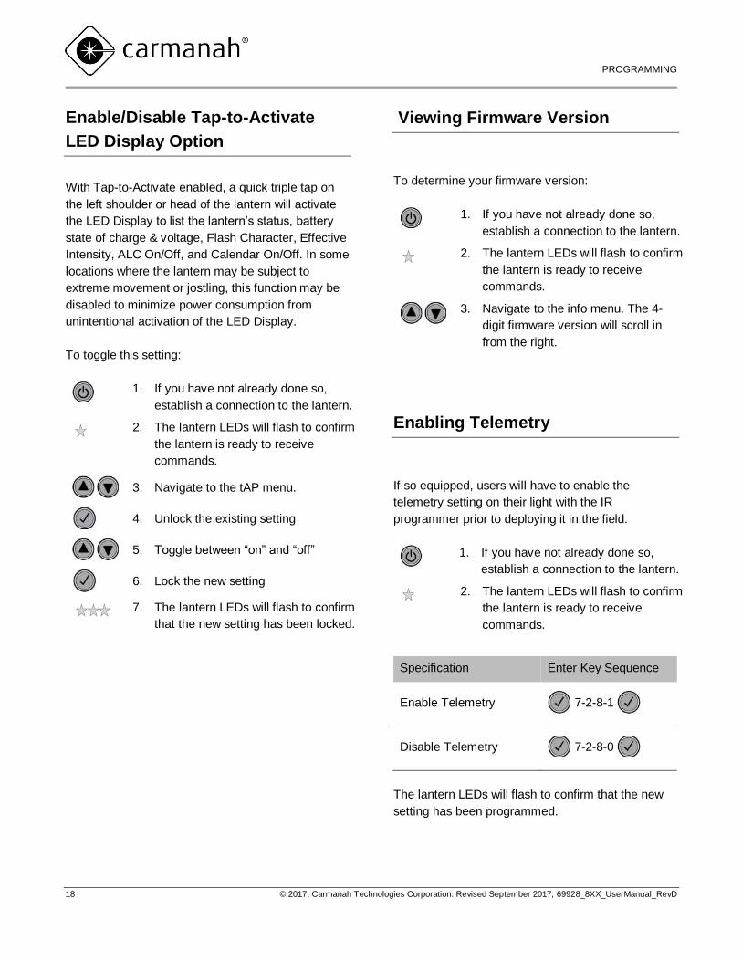
With Tap-to-Activate enabled, a quick triple tap on
the left shoulder or head of the lantern will activate
the LED Display to list the lantern’s status, battery
state of charge & voltage, Flash Character, Effective
Intensity, ALC On/Off, and Calendar On/Off. In some
locations where the lantern may be subject to
extreme movement or jostling, this function may be
disabled to minimize power consumption from
unintentional activation of the LED Display.
To toggle this setting:
1. If you have not already done so,
establish a connection to the lantern.
2. The lantern LEDs will flash to confirm
the lantern is ready to receive
commands.
3. Navigate to the tAP menu.
4. Unlock the existing setting
5. Toggle between “on” and “off”
6. Lock the new setting
7. The lantern LEDs will flash to confirm
that the new setting has been locked.
Viewing Firmware Version
To determine your firmware version:
1. If you have not already done so,
establish a connection to the lantern.
2. The lantern LEDs will flash to confirm
the lantern is ready to receive
commands.
3. Navigate to the info menu. The 4-
digit firmware version will scroll in
from the right.
Enabling Telemetry
If so equipped, users will have to enable the
telemetry setting on their light with the IR
programmer prior to deploying it in the field.
1. If you have not already done so,
establish a connection to the lantern.
2. The lantern LEDs will flash to confirm
the lantern is ready to receive
commands.
Specification Enter Key Sequence
Enable Telemetry 7-2-8-1
Disable Telemetry 7-2-8-0
The lantern LEDs will flash to confirm that the new
setting has been programmed.
800 SERIES USER MANUAL
PROGRAMMING
19 © 2017, Carmanah Technologies Corporation. Revised September 2017, 69928_8XX_UserManual_RevD
Setting the GPS Synchronization
Function (GPS-equipped Lanterns
Only)
To activate the GPS synchronization functionality of
the 800 Series lantern SYnC must be set to “on”.
Once activated, GPS-equipped lanterns
automatically synchronize with GPS-equipped
lanterns set to the same flash character; however, it
can take several minutes for lanterns to synchronize.
The synchronization period is dependent on the
number of satellites overhead and any obstructions
from buildings or mountainous terrain.
GPS-equipped lanterns will be
synched to Coordinated Universal
Time (UTC). The date/time settings
on GPS-equipped units cannot be
modified.
To toggle GPS Synchronization on or off:
1. If you have not already done so,
establish a connection to the lantern.
2. The lantern LEDs will flash to confirm
the lantern is ready to receive
commands.
3. Navigate to the SYnC menu.
4. Unlock the existing setting
5. Toggle between “on” and “off
6. Lock the new setting
7. The lantern LEDs will flash to confirm
that the new setting has been locked.
GPS Status (GPS-equipped
Lanterns Only)
GPS-equipped lanterns have the following four
additional status flags:
Good: GPS Satellite signal found and locked
PAuS: GPS function has been paused to
conserve energy. This will occur when GPS
function is not in use; for example, when the
lantern is in “stead-on” mode (flash code
001), or when the lantern is in dated shutdown.
SrcH: The GPS unit is searching for a satellite
signal
nLoC: The unit was unable to find and lock a
GPS satellite signal. Search will resume every
10 minutes at night and every 45 minutes during
the day until a signal is found.
To determine GPS state:
1. If you have not already done so,
establish a connection to the lantern.
2. The lantern LEDs will flash to confirm
the lantern is ready to receive
commands.
3. Navigate to the gPS menu. The GPS
state will scroll in from the right.
M850/M860 USER MANUAL
CHARGING
20 © 2017, Carmanah Technologies Corporation. Revised September 2017, 69928_8XX_UserManual_RevD
Installing a Lantern
Choosing a Suitable Location
Adequate sunlight and suitable ambient temperature
are the two most important factors to consider when
choosing a location for Carmanah solar lanterns.
Adequate Sunlight
The 800 Series lantern is powered by solar energy
stored inside the rechargeable batteries of the
lantern; therefore, to operate each night it requires
an adequate amount of sunlight to recharge its
batteries. The following factors should be considered
when installing the lantern:
the amount of sunlight available in the region
an unobstructed view of the sun (the lantern
should not be shaded)
seasonal changes in sun angle
Ambient Temperature
The temperature range of the lantern location must
be between –22 to 122 °F (–30 to 50 °C).
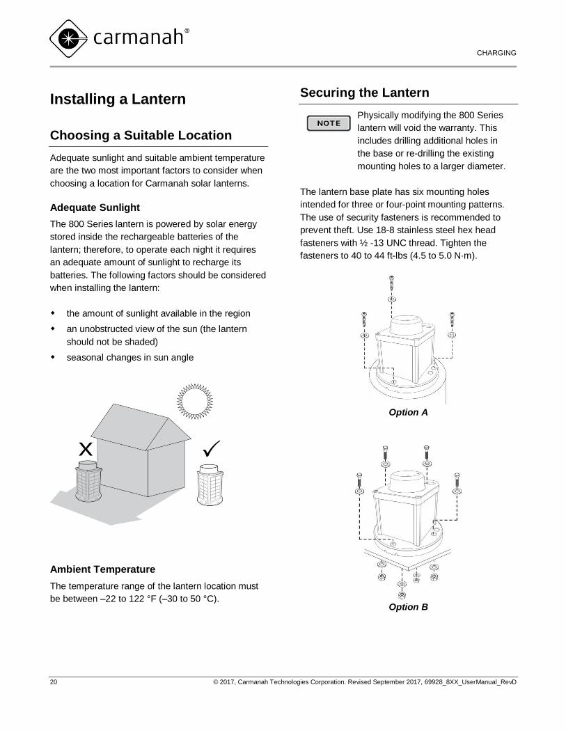
Securing the Lantern
Physically modifying the 800 Series
lantern will void the warranty. This
includes drilling additional holes in
the base or re-drilling the existing
mounting holes to a larger diameter.
The lantern base plate has six mounting holes
intended for three or four-point mounting patterns.
The use of security fasteners is recommended to
prevent theft. Use 18-8 stainless steel hex head
fasteners with ½ -13 UNC thread. Tighten the
fasteners to 40 to 44 ft-lbs (4.5 to 5.0 N·m).
Option A
Option B
M850/M860 USER MANUAL
CHARGING
21 © 2017, Carmanah Technologies Corporation. Revised September 2017, 69928_8XX_UserManual_RevD
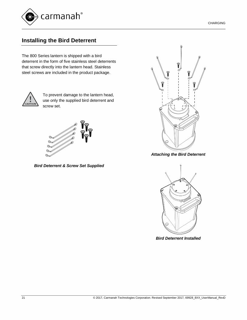
Installing the Bird Deterrent
The 800 Series lantern is shipped with a bird
deterrent in the form of five stainless steel deterrents
that screw directly into the lantern head. Stainless
steel screws are included in the product package.
To prevent damage to the lantern head,
use only the supplied bird deterrent and
screw set.
Bird Deterrent & Screw Set Supplied
Attaching the Bird Deterrent
Bird Deterrent Installed
M850/M860 USER MANUAL
CHARGING
22 © 2017, Carmanah Technologies Corporation. Revised September 2017, 69928_8XX_UserManual_RevD
Charging the Lantern
If the lantern batteries have a charge of less than
80%, they require charging.
It is recommended that you place the 800 Series
lantern in Off mode for charging. When it is in Off
mode, the lantern can continue to charge using light
on the solar panels, but does not turn on in
darkness.
To place the lantern into Off mode, follow the
command sequence described on page 122,
“Turning the Lantern On or Off”.
Sunlight
If available, sunlight is the easiest way to charge
multiple lanterns. The 800 Series lantern will
typically require five to 10 days to fully charge from
sunlight. Additional charging time may be required in
extremely low light conditions.
External Power Source
The 800 Series lantern may also be equipped with a
quick-access external charge port located in the
base of the lantern. Alternately, the lantern housing
may be removed to access an internal port. Using
either of these options, the light may achieve a full
state-of-charge overnight by connecting the charge
port to an external power source. The wall charger is
intended for indoor use only. Carmanah will supply a
wall charger with adapter on request.
Charge Indicator
When the battery is charging either from sunlight or
from the external charger, a single point on the lower
right of the lantern’s LED display will flash.
If the lantern has been stored
improperly, the batteries may be
sulphated and will not accept a
charge. A new battery may be
required.
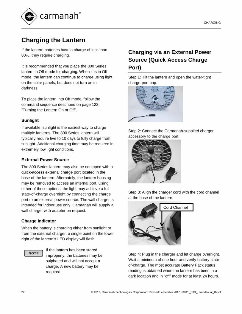
Charging via an External Power
Source (Quick Access Charge
Port)
Step 1: Tilt the lantern and open the water-tight
charge-port cap.
Step 2: Connect the Carmanah-supplied charger
accessory to the charge port.
Step 3: Align the charger cord with the cord channel
at the base of the lantern.
Step 4: Plug in the charger and let charge overnight.
Wait a minimum of one hour and verify battery state-
of-charge. The most accurate Battery Pack status
reading is obtained when the lantern has been in a
dark location and in “off” mode for at least 24 hours.
Cord Channel
M850/M860 USER MANUAL
CHARGING
23 © 2017, Carmanah Technologies Corporation. Revised September 2017, 69928_8XX_UserManual_RevD
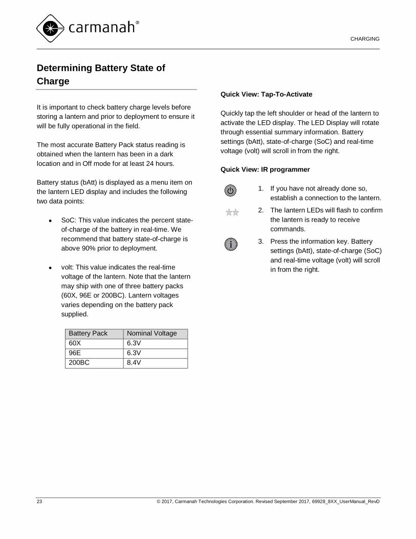
Determining Battery State of
Charge
It is important to check battery charge levels before
storing a lantern and prior to deployment to ensure it
will be fully operational in the field.
The most accurate Battery Pack status reading is
obtained when the lantern has been in a dark
location and in Off mode for at least 24 hours.
Battery status (bAtt) is displayed as a menu item on
the lantern LED display and includes the following
two data points:
SoC: This value indicates the percent state-
of-charge of the battery in real-time. We
recommend that battery state-of-charge is
above 90% prior to deployment.
volt: This value indicates the real-time
voltage of the lantern. Note that the lantern
may ship with one of three battery packs
(60X, 96E or 200BC). Lantern voltages
varies depending on the battery pack
supplied.
Battery Pack Nominal Voltage
60X 6.3V
96E 6.3V
200BC 8.4V
Quick View: Tap-To-Activate
Quickly tap the left shoulder or head of the lantern to
activate the LED display. The LED Display will rotate
through essential summary information. Battery
settings (bAtt), state-of-charge (SoC) and real-time
voltage (volt) will scroll in from the right.
Quick View: IR programmer
1. If you have not already done so,
establish a connection to the lantern.
2. The lantern LEDs will flash to confirm
the lantern is ready to receive
commands.
3. Press the information key. Battery
settings (bAtt), state-of-charge (SoC)
and real-time voltage (volt) will scroll
in from the right.

M850/M860 USER MANUAL
CHARGING
24 © 2017, Carmanah Technologies Corporation. Revised September 2017, 69928_8XX_UserManual_RevD
Changing the Battery
Battery replacement kits can be ordered directly
from Carmanah or from your authorized distributor.
Multiple battery sizes are available. Consult the table
below to match your 800 Series lantern with an
appropriate battery pack.
Pack Type Part No. Suitable for:
60X 69954 M850
OL800 Compact
96E 69955 M850/M860,
OL800 Standard
200BC 69956 M860
OL800 Large
Required tools:
Replacement Carmanah battery pack and
parts bag
¼” hex driver handle (required)
Ratchet with driver adapter (required)
½” socket (required)
Remove all jewelry including rings and
bracelets. Bridging battery terminals with
any metal could cause high electrical
currents and severe burns.
1. Turn the light off (refer to page 12 of this
manual for details).
2. Turn the lantern on its side. Use the ratchet
and driver to remove the four base plate
screws.
3. Hold the lantern by the base and head and
carefully return it to an upright position.
4. With the lantern in an upright position, slowly
lift the housing away from the base plate.
The base plate and housing
alignment.
5. Disconnect the battery harness and place
the housing to one side.
6. Using the ½” socket, remove the center bolt
and washer.

M850/M860 USER MANUAL
CHARGING
25 © 2017, Carmanah Technologies Corporation. Revised September 2017, 69928_8XX_UserManual_RevD
7. Lift out the battery pack. Remove the old
black rubber gasket in the lantern base and
replace it with the new one supplied.
Carefully check the gasket to
ensure it is seated in the base
plate.
8. Position the replacement pack in the lantern
base. Attach the new pack to the base using
the centre bolt and washer. Torque centre
bolt to 40 inch lbs.
9. Place the lantern housing back over the
battery pack and re-connect the battery
harness.
10. Carefully turn the lantern on its side. Inspect
the lantern to ensure that no wires or
gaskets are pinched.
11. Re-connect all four (4) base plate screws.
Tighten each screw down to 50 inch lbs
using a calibrated torque wrench.
12. Return the lantern upright. It is now ready to
be turned on and programme
M850/M860 USER MANUAL
WARRANTY & CUSTOMER SERVICE
26 © 2017, Carmanah Technologies Corporation. Revised September 2017, 69928_8XX_UserManual_RevD
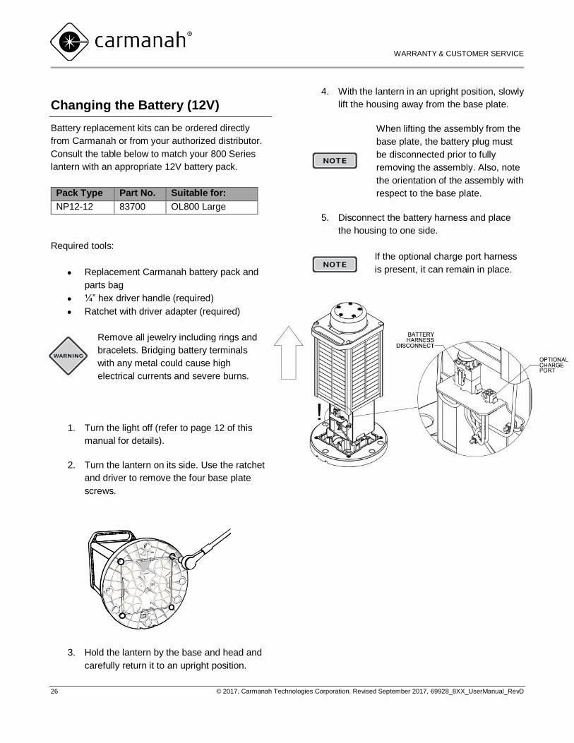
Changing the Battery (12V)
Battery replacement kits can be ordered directly
from Carmanah or from your authorized distributor.
Consult the table below to match your 800 Series
lantern with an appropriate 12V battery pack.
Pack Type Part No. Suitable for:
NP12-12 83700 OL800 Large
Required tools:
Replacement Carmanah battery pack and
parts bag
¼” hex driver handle (required)
Ratchet with driver adapter (required)
Remove all jewelry including rings and
bracelets. Bridging battery terminals
with any metal could cause high
electrical currents and severe burns.
1. Turn the light off (refer to page 12 of this
manual for details).
2. Turn the lantern on its side. Use the ratchet
and driver to remove the four base plate
screws.
3. Hold the lantern by the base and head and
carefully return it to an upright position.
4. With the lantern in an upright position, slowly
lift the housing away from the base plate.
When lifting the assembly from the
base plate, the battery plug must
be disconnected prior to fully
removing the assembly. Also, note
the orientation of the assembly with
respect to the base plate.
5. Disconnect the battery harness and place
the housing to one side.
If the optional charge port harness
is present, it can remain in place.
M850/M860 USER MANUAL
WARRANTY & CUSTOMER SERVICE
27 © 2017, Carmanah Technologies Corporation. Revised September 2017, 69928_8XX_UserManual_RevD
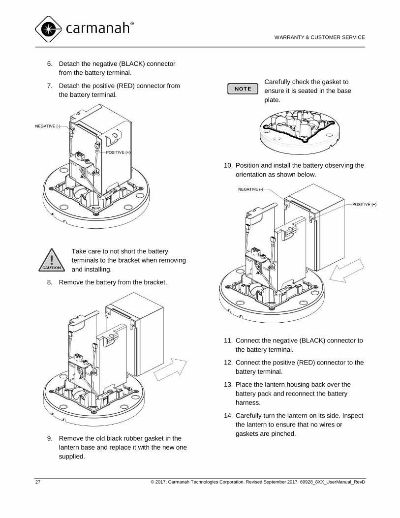
6. Detach the negative (BLACK) connector
from the battery terminal.
7. Detach the positive (RED) connector from
the battery terminal.
Take care to not short the battery
terminals to the bracket when removing
and installing.
8. Remove the battery from the bracket.
9. Remove the old black rubber gasket in the
lantern base and replace it with the new one
supplied.
Carefully check the gasket to
ensure it is seated in the base
plate.
10. Position and install the battery observing the
orientation as shown below.
11. Connect the negative (BLACK) connector to
the battery terminal.
12. Connect the positive (RED) connector to the
battery terminal.
13. Place the lantern housing back over the
battery pack and reconnect the battery
harness.
14. Carefully turn the lantern on its side. Inspect
the lantern to ensure that no wires or
gaskets are pinched.
M850/M860 USER MANUAL
WARRANTY & CUSTOMER SERVICE
28 © 2017, Carmanah Technologies Corporation. Revised September 2017, 69928_8XX_UserManual_RevD
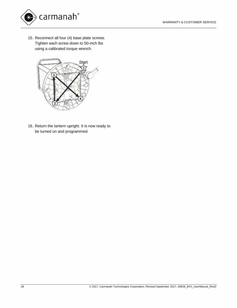
15. Reconnect all four (4) base plate screws.
Tighten each screw down to 50-inch lbs
using a calibrated torque wrench.
16. Return the lantern upright. It is now ready to
be turned on and programmed.
M850/M860 USER MANUAL
WARRANTY & CUSTOMER SERVICE
29 © 2017, Carmanah Technologies Corporation. Revised September 2017, 69928_8XX_UserManual_RevD
Preparing the Lantern for
Storage
To ensure optimal product life complete the following
steps prior to storing the lantern.
Check the current battery status of the
lantern. If the battery is not fully charged,
follow the charging instructions in this guide.
Place the lantern in “off” mode using the IR
programmer. Follow the instructions in this
guide on page 122, “Turning the Lantern On
or Off”.
Storage Maintenance/Duration
Elevated storage temperatures increase the rate of
battery self-discharge. The optimum storage
temperature for the 800 Series lantern is
68°F (20°C) or cooler.
Ensure that you have fully charged your 800 Series
lantern and placed it in “off” mode before placing it in
storage.
It is important to have a full battery
charge when placing the lantern into
storage. A fully charged battery
ensures maximum shelf life and
minimizes the possibility of battery
damage due to low-charge states.
Even in Storage Mode, the lantern
will continue to consume a small
amount of power.
M850/M860 USER MANUAL
WARRANTY & CUSTOMER SERVICE
30 © 2017, Carmanah Technologies Corporation. Revised September 2017, 69928_8XX_UserManual_RevD
Warranty and Customer
Service
Warranty
This product is covered by the Carmanah warranty.
Visit www.carmanah.com/content/products/warranty/
for additional information.
Additional Products
Carmanah offers a variety of solar-powered and
energy-efficient LED lighting products and
accessories. For more information visit
carmanah.com.
Customer Service
Before contacting Carmanah’s customer service
department, please have the serial number of the
lantern available, a brief description of the problem,
as well as all details of installation and recharging
efforts.
To contact Carmanah’s Customer Service
Department:
Mail:
Carmanah Technologies Corporation
250 Bay Street
Victoria, BC Canada V9A 3K5
Phone:
1.250.380.0052
877.722.8877 (Toll Free in U.S. and Canada)
Fax: 1.250.380.0062
Email: [email protected]
Website: carmanah.com
M850/M860 USER MANUAL
APPENDIX A: FLASH CHARACTERS
31 © 2017, Carmanah Technologies Corporation. Revised September 2017, 69928_8XX_UserManual_RevD
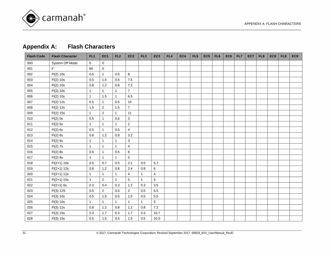
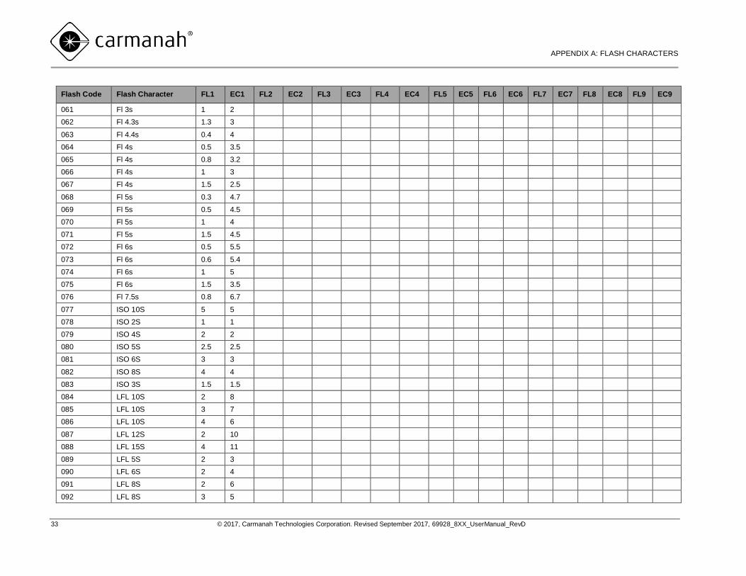
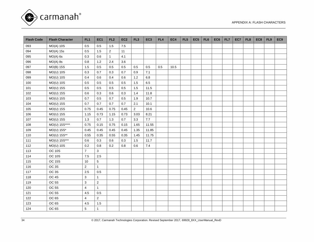
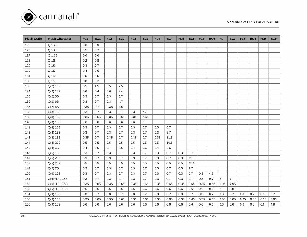
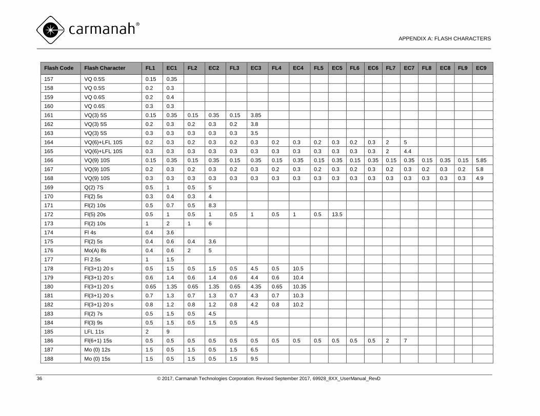
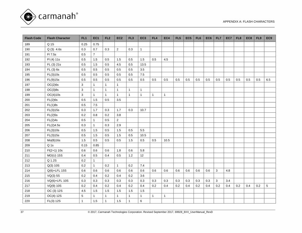
Appendix A: Flash Characters
Flash Code Flash Character FL1 EC1 FL2 EC2 FL3 EC3 FL4 EC4 FL5 EC5 FL6 EC6 FL7 EC7 FL8 EC8 FL9 EC9
000 System Off Mode 0 0
001 F 60 0
002 Fl(2) 10s 0.5 1 0.5 8
003 Fl(2) 10s 0.5 1.5 0.5 7.5
004 Fl(2) 10s 0.8 1.2 0.8 7.2
005 Fl(2) 10s 1 1 1 7
006 Fl(2) 10s 1 1.5 1 6.5
007 Fl(2) 12s 0.5 1 0.5 10
008 Fl(2) 12s 1.5 2 1.5 7
009 Fl(2) 15s 1 2 1 11
010 Fl(2) 5s 0.5 1 0.5 3
011 Fl(2) 5s 1 1 1 2
012 Fl(2) 6s 0.5 1 0.5 4
013 Fl(2) 6s 0.8 1.2 0.8 3.2
014 Fl(2) 6s 1 1 1 3
015 Fl(2) 7s 1 1 1 4
016 Fl(2) 8s 0.5 1 0.5 6
017 Fl(2) 8s 1 1 1 5
018 Fl(2+1) 10s 0.5 0.7 0.5 2.1 0.5 5.7
019 Fl(2+1) 12s 0.8 1.2 0.8 2.4 0.8 6
020 Fl(2+1) 12s 1 1 1 4 1 4
021 Fl(2+1) 15s 1 2 1 5 1 5
022 Fl(2+1) 6s 0.3 0.4 0.3 1.2 0.3 3.5
023 Fl(3) 12S 0.5 2 0.5 2 0.5 6.5
024 Fl(3) 10s 0.5 1.5 0.5 1.5 0.5 5.5
025 Fl(3) 10s 1 1 1 1 1 5
026 Fl(3) 12s 0.8 1.2 0.8 1.2 0.8 7.2
027 Fl(3) 15s 0.3 1.7 0.3 1.7 0.3 10.7
028 Fl(3) 15s 0.5 1.5 0.5 1.5 0.5 10.5
M850/M860 USER MANUAL
APPENDIX A: FLASH CHARACTERS
32 © 2017, Carmanah Technologies Corporation. Revised September 2017, 69928_8XX_UserManual_RevD
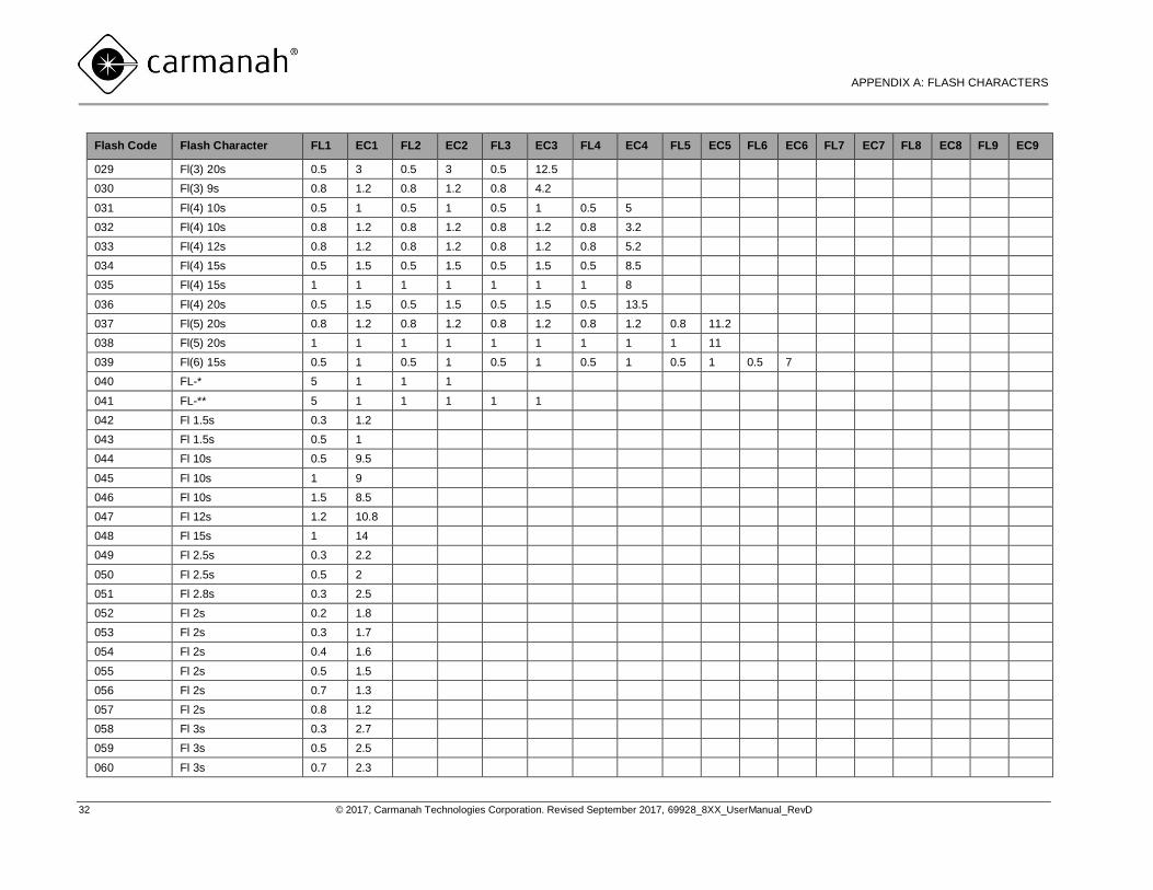
Flash Code Flash Character FL1 EC1 FL2 EC2 FL3 EC3 FL4 EC4 FL5 EC5 FL6 EC6 FL7 EC7 FL8 EC8 FL9 EC9
029 Fl(3) 20s 0.5 3 0.5 3 0.5 12.5
030 Fl(3) 9s 0.8 1.2 0.8 1.2 0.8 4.2
031 Fl(4) 10s 0.5 1 0.5 1 0.5 1 0.5 5
032 Fl(4) 10s 0.8 1.2 0.8 1.2 0.8 1.2 0.8 3.2
033 Fl(4) 12s 0.8 1.2 0.8 1.2 0.8 1.2 0.8 5.2
034 Fl(4) 15s 0.5 1.5 0.5 1.5 0.5 1.5 0.5 8.5
035 Fl(4) 15s 1 1 1 1 1 1 1 8
036 Fl(4) 20s 0.5 1.5 0.5 1.5 0.5 1.5 0.5 13.5
037 Fl(5) 20s 0.8 1.2 0.8 1.2 0.8 1.2 0.8 1.2 0.8 11.2
038 Fl(5) 20s 1 1 1 1 1 1 1 1 1 11
039 Fl(6) 15s 0.5 1 0.5 1 0.5 1 0.5 1 0.5 1 0.5 7
040 FL-* 5 1 1 1
041 FL-** 5 1 1 1 1 1
042 Fl 1.5s 0.3 1.2
043 Fl 1.5s 0.5 1
044 Fl 10s 0.5 9.5
045 Fl 10s 1 9
046 Fl 10s 1.5 8.5
047 Fl 12s 1.2 10.8
048 Fl 15s 1 14
049 Fl 2.5s 0.3 2.2
050 Fl 2.5s 0.5 2
051 Fl 2.8s 0.3 2.5
052 Fl 2s 0.2 1.8
053 Fl 2s 0.3 1.7
054 Fl 2s 0.4 1.6
055 Fl 2s 0.5 1.5
056 Fl 2s 0.7 1.3
057 Fl 2s 0.8 1.2
058 Fl 3s 0.3 2.7
059 Fl 3s 0.5 2.5
060 Fl 3s 0.7 2.3
M850/M860 USER MANUAL
APPENDIX A: FLASH CHARACTERS
33 © 2017, Carmanah Technologies Corporation. Revised September 2017, 69928_8XX_UserManual_RevD
Flash Code Flash Character FL1 EC1 FL2 EC2 FL3 EC3 FL4 EC4 FL5 EC5 FL6 EC6 FL7 EC7 FL8 EC8 FL9 EC9
061 Fl 3s 1 2
062 Fl 4.3s 1.3 3
063 Fl 4.4s 0.4 4
064 Fl 4s 0.5 3.5
065 Fl 4s 0.8 3.2
066 Fl 4s 1 3
067 Fl 4s 1.5 2.5
068 Fl 5s 0.3 4.7
069 Fl 5s 0.5 4.5
070 Fl 5s 1 4
071 Fl 5s 1.5 4.5
072 Fl 6s 0.5 5.5
073 Fl 6s 0.6 5.4
074 Fl 6s 1 5
075 Fl 6s 1.5 3.5
076 Fl 7.5s 0.8 6.7
077 ISO 10S 5 5
078 ISO 2S 1 1
079 ISO 4S 2 2
080 ISO 5S 2.5 2.5
081 ISO 6S 3 3
082 ISO 8S 4 4
083 ISO 3S 1.5 1.5
084 LFL 10S 2 8
085 LFL 10S 3 7
086 LFL 10S 4 6
087 LFL 12S 2 10
088 LFL 15S 4 11
089 LFL 5S 2 3
090 LFL 6S 2 4
091 LFL 8S 2 6
092 LFL 8S 3 5
M850/M860 USER MANUAL
APPENDIX A: FLASH CHARACTERS
34 © 2017, Carmanah Technologies Corporation. Revised September 2017, 69928_8XX_UserManual_RevD
Flash Code Flash Character FL1 EC1 FL2 EC2 FL3 EC3 FL4 EC4 FL5 EC5 FL6 EC6 FL7 EC7 FL8 EC8 FL9 EC9
093 MO(A) 10S 0.5 0.5 1.5 7.5
094 MO(A) 15s 0.5 1.5 2 11
095 MO(A) 6s 0.3 0.6 1 4.1
096 MO(A) 8s 0.8 1.2 2.4 3.6
097 MO(B) 15S 1.5 0.5 0.5 0.5 0.5 0.5 0.5 10.5
098 MO(U) 10S 0.3 0.7 0.3 0.7 0.9 7.1
099 MO(U) 10S 0.4 0.6 0.4 0.6 1.2 6.8
100 MO(U) 10S 0.5 0.5 0.5 0.5 1.5 6.5
101 MO(U) 15S 0.5 0.5 0.5 0.5 1.5 11.5
102 MO(U) 15S 0.6 0.3 0.6 0.3 1.4 11.8
103 MO(U) 15S 0.7 0.5 0.7 0.5 1.9 10.7
104 MO(U) 15S 0.7 0.7 0.7 0.7 2.1 10.1
105 MO(U) 15S 0.75 0.45 0.75 0.45 2 10.6
106 MO(U) 15S 1.15 0.73 1.15 0.73 3.03 8.21
107 MO(U) 15S 1.3 0.7 1.3 0.7 3.3 7.7
108 MO(U) 15S**** 0.75 0.15 0.75 0.15 1.65 11.55
109 MO(U) 15S* 0.45 0.45 0.45 0.45 1.35 11.85
110 MO(U) 15S** 0.55 0.35 0.55 0.35 1.45 11.75
111 MO(U) 15S*** 0.6 0.3 0.6 0.3 1.5 11.7
112 MO(U) 10S 0.2 0.8 0.2 0.8 0.6 7.4
113 OC 10S 7 3
114 OC 10S 7.5 2.5
115 OC 15S 10 5
116 OC 3S 2 1
117 OC 3S 2.5 0.5
118 OC 4S 3 1
119 OC 5S 3 2
120 OC 5S 4 1
121 OC 5S 4.5 0.5
122 OC 6S 4 2
123 OC 6S 4.5 1.5
124 OC 6S 5 1
M850/M860 USER MANUAL
APPENDIX A: FLASH CHARACTERS
35 © 2017, Carmanah Technologies Corporation. Revised September 2017, 69928_8XX_UserManual_RevD
Flash Code Flash Character FL1 EC1 FL2 EC2 FL3 EC3 FL4 EC4 FL5 EC5 FL6 EC6 FL7 EC7 FL8 EC8 FL9 EC9
125 Q 1.2S 0.3 0.9
126 Q 1.2S 0.5 0.7
127 Q 1.2S 0.6 0.6
128 Q 1S 0.2 0.8
129 Q 1S 0.3 0.7
130 Q 1S 0.4 0.6
131 Q 1S 0.5 0.5
132 Q 1S 0.8 0.2
133 Q(2) 10S 0.5 1.5 0.5 7.5
134 Q(2) 10S 0.6 0.4 0.6 8.4
135 Q(2) 5S 0.3 0.7 0.3 3.7
136 Q(2) 6S 0.3 0.7 0.3 4.7
137 Q(2) 6S 0.35 0.7 0.35 4.6
138 Q(3) 10S 0.3 0.7 0.3 0.7 0.3 7.7
139 Q(3) 10S 0.35 0.65 0.35 0.65 0.35 7.65
140 Q(3) 10S 0.6 0.6 0.6 0.6 0.6 7
141 Q(4) 10S 0.3 0.7 0.3 0.7 0.3 0.7 0.3 6.7
142 Q(4) 12S 0.3 0.7 0.3 0.7 0.3 0.7 0.3 8.7
143 Q(4) 15S 0.35 0.7 0.35 0.7 0.35 0.7 0.35 11.5
144 Q(4) 20S 0.5 0.5 0.5 0.5 0.5 0.5 0.5 16.5
145 Q(4) 6S 0.4 0.6 0.4 0.6 0.4 0.6 0.4 2.6
146 Q(5) 10S 0.3 0.7 0.3 0.7 0.3 0.7 0.3 0.7 0.3 5.7
147 Q(5) 20S 0.3 0.7 0.3 0.7 0.3 0.7 0.3 0.7 0.3 15.7
148 Q(5) 20S 0.5 0.5 0.5 0.5 0.5 0.5 0.5 0.5 0.5 15.5
149 Q(5) 7S 0.3 0.7 0.3 0.7 0.3 0.7 0.3 0.7 0.3 2.7
150 Q(6) 10S 0.3 0.7 0.3 0.7 0.3 0.7 0.3 0.7 0.3 0.7 0.3 4.7
151 Q(6)+LFL 15S 0.3 0.7 0.3 0.7 0.3 0.7 0.3 0.7 0.3 0.7 0.3 0.7 2 7
152 Q(6)+LFL 15S 0.35 0.65 0.35 0.65 0.35 0.65 0.35 0.65 0.35 0.65 0.35 0.65 1.05 7.95
153 Q(6)+LFL 15S 0.6 0.6 0.6 0.6 0.6 0.6 0.6 0.6 0.6 0.6 0.6 0.6 2 5.8
154 Q(9) 15S 0.3 0.7 0.3 0.7 0.3 0.7 0.3 0.7 0.3 0.7 0.3 0.7 0.3 0.7 0.3 0.7 0.3 6.7
155 Q(9) 15S 0.35 0.65 0.35 0.65 0.35 0.65 0.35 0.65 0.35 0.65 0.35 0.65 0.35 0.65 0.35 0.65 0.35 6.65
156 Q(9) 15S 0.6 0.6 0.6 0.6 0.6 0.6 0.6 0.6 0.6 0.6 0.6 0.6 0.6 0.6 0.6 0.6 0.6 4.8
M850/M860 USER MANUAL
APPENDIX A: FLASH CHARACTERS
36 © 2017, Carmanah Technologies Corporation. Revised September 2017, 69928_8XX_UserManual_RevD
Flash Code Flash Character FL1 EC1 FL2 EC2 FL3 EC3 FL4 EC4 FL5 EC5 FL6 EC6 FL7 EC7 FL8 EC8 FL9 EC9
157 VQ 0.5S 0.15 0.35
158 VQ 0.5S 0.2 0.3
159 VQ 0.6S 0.2 0.4
160 VQ 0.6S 0.3 0.3
161 VQ(3) 5S 0.15 0.35 0.15 0.35 0.15 3.85
162 VQ(3) 5S 0.2 0.3 0.2 0.3 0.2 3.8
163 VQ(3) 5S 0.3 0.3 0.3 0.3 0.3 3.5
164 VQ(6)+LFL 10S 0.2 0.3 0.2 0.3 0.2 0.3 0.2 0.3 0.2 0.3 0.2 0.3 2 5
165 VQ(6)+LFL 10S 0.3 0.3 0.3 0.3 0.3 0.3 0.3 0.3 0.3 0.3 0.3 0.3 2 4.4
166 VQ(9) 10S 0.15 0.35 0.15 0.35 0.15 0.35 0.15 0.35 0.15 0.35 0.15 0.35 0.15 0.35 0.15 0.35 0.15 5.85
167 VQ(9) 10S 0.2 0.3 0.2 0.3 0.2 0.3 0.2 0.3 0.2 0.3 0.2 0.3 0.2 0.3 0.2 0.3 0.2 5.8
168 VQ(9) 10S 0.3 0.3 0.3 0.3 0.3 0.3 0.3 0.3 0.3 0.3 0.3 0.3 0.3 0.3 0.3 0.3 0.3 4.9
169 Q(2) 7S 0.5 1 0.5 5
170 Fl(2) 5s 0.3 0.4 0.3 4
171 Fl(2) 10s 0.5 0.7 0.5 8.3
172 Fl(5) 20s 0.5 1 0.5 1 0.5 1 0.5 1 0.5 13.5
173 Fl(2) 10s 1 2 1 6
174 Fl 4s 0.4 3.6
175 Fl(2) 5s 0.4 0.6 0.4 3.6
176 Mo(A) 8s 0.4 0.6 2 5
177 Fl 2.5s 1 1.5
178 Fl(3+1) 20 s 0.5 1.5 0.5 1.5 0.5 4.5 0.5 10.5
179 Fl(3+1) 20 s 0.6 1.4 0.6 1.4 0.6 4.4 0.6 10.4
180 Fl(3+1) 20 s 0.65 1.35 0.65 1.35 0.65 4.35 0.65 10.35
181 Fl(3+1) 20 s 0.7 1.3 0.7 1.3 0.7 4.3 0.7 10.3
182 Fl(3+1) 20 s 0.8 1.2 0.8 1.2 0.8 4.2 0.8 10.2
183 Fl(2) 7s 0.5 1.5 0.5 4.5
184 Fl(3) 9s 0.5 1.5 0.5 1.5 0.5 4.5
185 LFL 11s 2 9
186 Fl(6+1) 15s 0.5 0.5 0.5 0.5 0.5 0.5 0.5 0.5 0.5 0.5 0.5 0.5 2 7
187 Mo (0) 12s 1.5 0.5 1.5 0.5 1.5 6.5
188 Mo (0) 15s 1.5 0.5 1.5 0.5 1.5 9.5
M850/M860 USER MANUAL
APPENDIX A: FLASH CHARACTERS
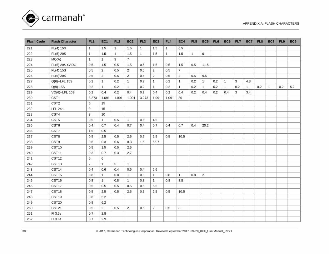
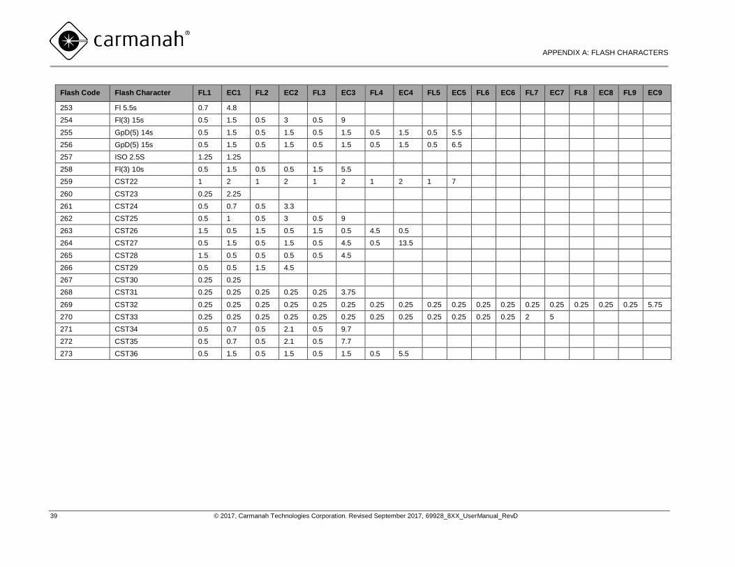
37 © 2017, Carmanah Technologies Corporation. Revised September 2017, 69928_8XX_UserManual_RevD
Flash Code Flash Character FL1 EC1 FL2 EC2 FL3 EC3 FL4 EC4 FL5 EC5 FL6 EC6 FL7 EC7 FL8 EC8 FL9 EC9
189 Q 1S 0.25 0.75
190 Q (3) 4.6s 0.3 0.7 0.3 2 0.3 1
191 Fl 7.5s 0.5 7
192 Fl (4) 11s 0.5 1.5 0.5 1.5 0.5 1.5 0.5 4.5
193 FL (3) 21s 0.5 1.5 0.5 4.5 0.5 13.5
194 FL (3) 6s 0.5 0.5 0.5 0.5 0.5 3.5
195 FL(3)10s 0.5 0.5 0.5 0.5 0.5 7.5
196 FL(9)15s 0.5 0.5 0.5 0.5 0.5 0.5 0.5 0.5 0.5 0.5 0.5 0.5 0.5 0.5 0.5 0.5 0.5 6.5
197 OC(2)6s 3 1 1 1
198 OC(3)8s 3 1 1 1 1 1
199 OC(4)10s 3 1 1 1 1 1 1 1
200 FL(2)6s 0.5 1.5 0.5 3.5
201 FL(1)8s 0.5 7.5
202 FL(3)15s 0.3 1.7 0.3 1.7 0.3 10.7
203 FL(2)5s 0.2 0.8 0.2 3.8
204 FL(2)4s 0.5 1 0.5 2
205 FL(2)4.5s 0.3 1 0.3 2.9
206 FL(3)10s 0.5 1.5 0.5 1.5 0.5 5.5
207 FL(3)15s 0.5 1.5 0.5 1.5 0.5 10.5
208 Mo(B)16s 1.5 0.5 0.5 0.5 1.5 0.5 0.5 10.5
209 Q 1s 0.15 0.85
210 Fl(2+1) 10s 0.6 0.6 0.6 1.8 0.6 5.8
211 MO(U) 15S 0.4 0.5 0.4 0.5 1.2 12
212 Q 1.2S 0.2 1
213 Q(3) 10S 0.2 1 0.2 1 0.2 7.4
214 Q(6)+LFL 15S 0.6 0.6 0.6 0.6 0.6 0.6 0.6 0.6 0.6 0.6 0.6 0.6 3 4.8
215 VQ(3) 5S 0.2 0.4 0.2 0.4 0.2 3.6
216 VQ(6)+LFL 10S 0.3 0.3 0.3 0.3 0.3 0.3 0.3 0.3 0.3 0.3 0.3 0.3 3 3.4
217 VQ(9) 10S 0.2 0.4 0.2 0.4 0.2 0.4 0.2 0.4 0.2 0.4 0.2 0.4 0.2 0.4 0.2 0.4 0.2 5
218 OC (3) 12S 4.5 1.5 1.5 1.5 1.5 1.5
219 OC(4) 12S 5 1 1 1 1 1 1 1
220 FL(3) 12S 1 1.5 1 1.5 1 6
M850/M860 USER MANUAL
APPENDIX A: FLASH CHARACTERS
38 © 2017, Carmanah Technologies Corporation. Revised September 2017, 69928_8XX_UserManual_RevD
Flash Code Flash Character FL1 EC1 FL2 EC2 FL3 EC3 FL4 EC4 FL5 EC5 FL6 EC6 FL7 EC7 FL8 EC8 FL9 EC9
221 FL(4) 15S 1 1.5 1 1.5 1 1.5 1 6.5
222 FL(5) 20S 1 1.5 1 1.5 1 1.5 1 1.5 1 9
223 MO(A) 1 1 3 7
224 FL(5) 20S SADO 0.5 1.5 0.5 1.5 0.5 1.5 0.5 1.5 0.5 11.5
225 FL(4) 15S 0.5 2 0.5 2 0.5 2 0.5 7
226 FL(5) 20S 0.5 2 0.5 2 0.5 2 0.5 2 0.5 9.5
227 Q(6)+LFL 15S 0.2 1 0.2 1 0.2 1 0.2 1 0.2 1 0.2 1 3 4.8
228 Q(9) 15S 0.2 1 0.2 1 0.2 1 0.2 1 0.2 1 0.2 1 0.2 1 0.2 1 0.2 5.2
229 VQ(6)+LFL 10S 0.2 0.4 0.2 0.4 0.2 0.4 0.2 0.4 0.2 0.4 0.2 0.4 3 3.4
230 CST1 3.273 1.091 1.091 1.091 3.273 1.091 1.091 30
231 CST2 6 15
232 LFL 24s 9 15
233 CST4 3 10
234 CST5 0.5 1 0.5 1 0.5 4.5
235 CST6 0.4 0.7 0.4 0.7 0.4 0.7 0.4 0.7 0.4 20.2
236 CST7 1.5 0.5
237 CST8 0.5 2.5 0.5 2.5 0.5 2.5 0.5 10.5
238 CST9 0.6 0.3 0.6 0.3 1.5 56.7
239 CST10 0.5 1.5 0.5 2.5
240 CST11 0.3 0.7 0.3 2.7
241 CST12 6 6
242 CST13 2 1 5 1
243 CST14 0.4 0.6 0.4 0.6 0.4 2.6
244 CST15 0.8 1 0.8 1 0.8 1 0.8 1 0.8 2
245 CST16 0.8 1 0.8 1 0.8 1 0.8 3.8
246 CST17 0.5 0.5 0.5 0.5 0.5 5.5
247 CST18 0.5 2.5 0.5 2.5 0.5 2.5 0.5 10.5
248 CST19 0.8 5.2
249 CST20 0.8 6.2
250 CST21 0.5 2 0.5 2 0.5 2 0.5 8
251 Fl 3.5s 0.7 2.8
252 Fl 3.6s 0.7 2.9
M850/M860 USER MANUAL
APPENDIX A: FLASH CHARACTERS
39 © 2017, Carmanah Technologies Corporation. Revised September 2017, 69928_8XX_UserManual_RevD
Flash Code Flash Character FL1 EC1 FL2 EC2 FL3 EC3 FL4 EC4 FL5 EC5 FL6 EC6 FL7 EC7 FL8 EC8 FL9 EC9
253 Fl 5.5s 0.7 4.8
254 Fl(3) 15s 0.5 1.5 0.5 3 0.5 9
255 GpD(5) 14s 0.5 1.5 0.5 1.5 0.5 1.5 0.5 1.5 0.5 5.5
256 GpD(5) 15s 0.5 1.5 0.5 1.5 0.5 1.5 0.5 1.5 0.5 6.5
257 ISO 2.5S 1.25 1.25
258 Fl(3) 10s 0.5 1.5 0.5 0.5 1.5 5.5
259 CST22 1 2 1 2 1 2 1 2 1 7
260 CST23 0.25 2.25
261 CST24 0.5 0.7 0.5 3.3
262 CST25 0.5 1 0.5 3 0.5 9
263 CST26 1.5 0.5 1.5 0.5 1.5 0.5 4.5 0.5
264 CST27 0.5 1.5 0.5 1.5 0.5 4.5 0.5 13.5
265 CST28 1.5 0.5 0.5 0.5 0.5 4.5
266 CST29 0.5 0.5 1.5 4.5
267 CST30 0.25 0.25
268 CST31 0.25 0.25 0.25 0.25 0.25 3.75
269 CST32 0.25 0.25 0.25 0.25 0.25 0.25 0.25 0.25 0.25 0.25 0.25 0.25 0.25 0.25 0.25 0.25 0.25 5.75
270 CST33 0.25 0.25 0.25 0.25 0.25 0.25 0.25 0.25 0.25 0.25 0.25 0.25 2 5
271 CST34 0.5 0.7 0.5 2.1 0.5 9.7
272 CST35 0.5 0.7 0.5 2.1 0.5 7.7
273 CST36 0.5 1.5 0.5 1.5 0.5 1.5 0.5 5.5
M850/M860 USER MANUAL
APPENDIX B: TROUBLESHOOTING
40 © 2017, Carmanah Technologies Corporation. Revised September 2017, 69928_8XX_UserManual_RevD
Appendix B: Troubleshooting
Failure Possible Cause Recommendation
The IR programmer will
not connect to the
lantern
IR programmer battery On a new IR programmer, confirm that the protective battery
tab on the bottom back of the IR programmer has been
removed and that the battery is charged. For an older IR
programmer confirm that the batteries are charged.
The lantern searches for an
IR signal on a 0.5 second
cycle. The lantern’s search
signal may not coincide with
the push of the power
button, or there may be
local interference.
Place the programmer close (no more than 6” or 15 cm) to the
top clear lens. Press the power button on the IR programmer
quickly and repeatedly over a period of two seconds. The
lantern LEDs should flash when a connection has been
established.
A new lantern may have
been shipped in factory
mode and been received
within two hours.
Tap quickly three times on the lantern head or left shoulder to
activate the LED display. If the “stat” menu item shows a
status of “stor”, leave the lantern for two hours (from the time
the display was activated). After a two hour period, the lantern
will automatically switch from “stor” to “on”.
The tap-to-activate
function does not turn
on the LED display
Tap-to-activate has been
turned off
You will need an IR programmer to reactivate this function
following the instructions on page 188 of this manual.
The IR programmer will
not edit the lantern’s
settings – or all menu
items are not appearing
on the display.
The lantern may be in “off”
mode.
Tap quickly three times on the lantern head or left shoulder to
activate the LED display or press several times on the IR
programmer. Verify if the lantern status (stat) is “off. Follow
the instructions “Turning the Lantern On or Off” as described
on page 12 Turning the Lantern On or Off of this manual.
An Error (Err) message
appears when
programming a lantern
The value entered is invalid An Error (Err) message appears when attempting to enter a
value that exceeds the lantern’s acceptable parameters.
For dates and times: Verify that the value entered is a valid
calendar date.
For Flash Character or Effective Intensity: Review the online
simulator tool at carmanah.com/selector and confirm
sustainable settings for your installation location.
Lantern beam/LEDs do
not turn on
The environment is too
bright to activate the lantern
The lantern automatically turns on in the dark – test it in a dark
environment. Check the day-to-night transition level following
the instructions on page 177 of this manual.
The lantern is in low voltage
disconnect state
Charge the battery. If the charging indicator LED is not
flashing, follow the charging instruction on page 222 of this
manual.
M850/M860 USER MANUAL
APPENDIX B: TROUBLESHOOTING
41 © 2017, Carmanah Technologies Corporation. Revised September 2017, 69928_8XX_UserManual_RevD
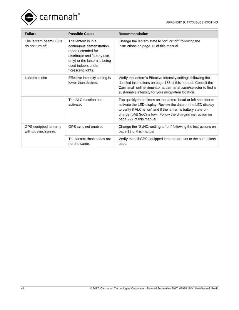
Failure Possible Cause Recommendation
The lantern beam/LEDs
do not turn off
The lantern is in a
continuous demonstration
mode (intended for
distributor and factory use
only) or the lantern is being
used indoors under
florescent lights.
Change the lantern state to “on” or “off” following the
instructions on page 12 of this manual.
Lantern is dim Effective intensity setting is
lower than desired.
Verify the lantern’s Effective Intensity settings following the
detailed instructions on page 133 of this manual. Consult the
Carmanah online simulator at carmanah.com/selector to find a
sustainable intensity for your installation location.
The ALC function has
activated
Tap quickly three times on the lantern head or left shoulder to
activate the LED display. Review the data on the LED display
to verify if ALC is “on” and if the lantern’s battery state-of-
charge (bAtt SoC) is low. Follow the charging instruction on
page 222 of this manual.
GPS equipped lanterns
will not synchronize.
GPS sync not enabled Change the “SyNC: setting to “on” following the instructions on
page 19 of this manual.
The lantern flash codes are
not the same.
Verify that all GPS equipped lanterns are set to the same flash
code.

© 2017, Carmanah Technologies Corporation. Revised September 2017. 69928_8XX_UserManual_RevD
© 2017 Carmanah Technologies Corporation
carmanah.com
Technical support: [email protected]
Toll Free in Canada and the U.S.: 1.877.722.8877
International: 1.250.380.0052 | Fax: 1.250.380.0062
Number: 69928_8xx_UserManual_RevD