815.301 scada specification rev0
TRANSCRIPT

THU DUC III Specification for Supervisory Control And Data Acquisition (SCADA)
810-301-PR-930-E-XXX Rev 0
29-Oct-2014

THU DUC III
INSTRUMENT SPECIFICATION FOR DISTRIBUTED CONTROL SYSTEM (DCS)PLC – SCADA SYSTEM
CONTENTS
1. INTRODUCTION............................................................................................................ 1
1.1 Scope of Specification........................................................................................... 1
1.2 Description of Plant ............................................................................................... 5
1.3 Scope of Supply ................................................................................................... 6
1.4 Project Specifications ...........................................................................................10
1.5 Definitions & Abbreviations ...................................................................................10
1.6 Vendor Exceptions ...............................................................................................11
1.7 Order of Precedence............................................................................................12
1.8 Language ............................................................................................................12
2. REGULATIONS, CODES & STANDARDS .....................................................................13
2.1 Codes and Standards ..........................................................................................13
2.2 Regulations .........................................................................................................14
3. GENERAL REQUIREMENTS ........................................................................................15
3.1 Operation & Design Life .......................................................................................15
3.2 Environmental Conditions .....................................................................................15
3.3 Utility Data...........................................................................................................15
3.4 Materials .............................................................................................................15
3.5 HSE Requirements ..............................................................................................15
3.6 Hazardous Area/ IP Rating ....................................................................................16
3.7 Transportation Loads ...........................................................................................16
3.8 Certifying Authority ..............................................................................................16
3.9 Units of Measurement ..........................................................................................17
4. TECHNICAL REQUIREMENTS .....................................................................................18
4.1 Statement of SCADA Vendor’s Responsibility ........................................................29
4.2 SCADA System Topology ....................................................................................31
4.3 Instrument System Interfaces ...............................................................................31
4.4 SCADA Hardware Design Requirements ...............................................................34
4.5 Field Signal Characteristics ..................................................................................38
4.6 System Performance ...........................................................................................41
4.7 SCADA Communications .....................................................................................43
4.8 SCADA Software .................................................................................................45
4.9 Power Supply Arrangements ................................................................................56
4.10 Earthing ..............................................................................................................56
4.11 Cabinet, Wireways, Termination, Cabling and Tagging...........................................58
5. TESTING......................................................................................................................60

THU DUC III
INSTRUMENT SPECIFICATION FOR DISTRIBUTED CONTROL SYSTEM (DCS)PLC – SCADA SYSTEM
5.1 Factory Acceptance Testing .................................................................................60
5.2 Site Acceptance Tests .........................................................................................60
5.3 System Initialisation, Commissioning and Start-up .................................................61
5.4 Site Support ........................................................................................................61
6. PROTECTIVE COATINGS ............................................................................................62
7. NAMEPLATE DETAILS ................................................................................................63
7.1 Primary Nameplate ..............................................................................................63
7.2 Tag Plates ...........................................................................................................63

THU DUC III
INSTRUMENT SPECIFICATION FOR DISTRIBUTED CONTROL SYSTEM (DCS)PLC – SCADA SYSTEM
1. INTRODUCTION
1.1 Summar y for System:
ICA PANEL AT CONTROL ROOM – HOA AN
SUMMARY FOR 800 ICA 01
SUM SPARE TOTAL SELECTED Remark
PLC S7 300 2 0 2 2
HMI 2 0 2 2
Tough HMI, 10” color (1 for MV
and 1 for LV system)
DI 204 40.8 244.8 16 Sixteen DI card (16 nodes type)
DO 103 20.6 123.6 8 Eigh DO card (16 nodes type)
AI 45 9 54 7 Seven AI Card (8 nodes type)
AI HART 9 8 17 2 Two AI Hart Card (8 nodes type)
AO 7 8 15 2 Two AO Card (8 nodes type)
ET200M 10
OPTICAL LINK 6
Power supply 24
VDC 1
UPS 230VAC
1
Cable for
connection 1
ACCESSORIES 1
ICA PANEL AT CONTROL ROOM - CWPS
SUMMARY FOR 802 ICA 01
SUM SPARE TOTAL SELECTED Remark
HMI 2 0 2 2
Tough HMI, 10” color (1 for MV and 1 for LV system)
DI 204 40.8 244.8 16 Sixteen DI card (16 nodes type)
DO 103 20.6 123.6 8 Eigh DO card (16 nodes type)
AI 45 9 54 7 Seven AI Card (8 nodes type)
AI HART 9 8 17 2 Two AI Hart Card (8 nodes type)
AO 7 8 15 2 Two AO Card (8 nodes type)
ET200M 10
OPTICAL LINK 6
Power supply 24 VDC
1
UPS 230VAC 1
Cable for
connection 1
ACCESSORIES 1

THU DUC III
INSTRUMENT SPECIFICATION FOR DISTRIBUTED CONTROL SYSTEM (DCS)PLC – SCADA SYSTEM
ICA PANEL AT ELECTRIC ROOM - WTP
SUMMARY FOR 801 ICA 01
SUM SPARE TOTAL SELECTED Remark
PLC S7 412 H 2 0 2 2 Redundancy
HMI 1 0 1 1 Tough HMI, 10” color
DI 100 20 120 8 Sixteen DI card (16 nodes type)
DO 23 4.6 27.6 2 Eigh DO card (16 nodes type)
AI 4 0.8 4.8 1 Seven AI Card (8 nodes type)
AI HART 0 0 1 Two AI Hart Card (8 nodes type)
AO 1 2 3 1 Two AO Card (8 nodes type)
ET200M 4
OPTICAL LINK 6
Power supply 24 VDC
1
UPS 230 VAC 1
Cable for connection
1
ACCESSORIES 1
ICA PANEL – LME 1+2
SUMMARY FOR 151.1 ICA 01
SUM SPARE TOTAL SELECTED Remark
HMI 1 0 1 1 Tough HMI, 10” color
DI 61 24.4 85.4 6 Sixteen DI card (16 nodes type)
DO 17 6.8 23.8 4 Eigh DO card (16 nodes type)
AI 16 3.2 19.2 1 Seven AI Card (8 nodes type)
AI HART 4 4 8 1 Two AI Hart Card (8 nodes type)
AO 5 3 8 1 Two AO Card (8 nodes type)
ET200M 4
OPTICAL LINK 4
Power supply 24 VDC
1
UPS 230 VAC 1
Cable for connection
1
ACCESSORIES 1

THU DUC III
INSTRUMENT SPECIFICATION FOR DISTRIBUTED CONTROL SYSTEM (DCS)PLC – SCADA SYSTEM
ICA PANEL – LME 3+4
SUMMARY FOR 151.3 ICA
01
SUM SPARE TOTAL SELECTED Remark
HMI 1 0 1 1 Tough HMI, 10” color
DI 61 24.4 85.4 6 Sixteen DI card (16 nodes type)
DO 17 6.8 23.8 4 Eigh DO card (16 nodes type)
AI 16 3.2 19.2 1 Seven AI Card (8 nodes type)
AI HART 4 4 8 1 Two AI Hart Card (8 nodes type)
AO 5 3 8 1 Two AO Card (8 nodes type)
ET200M 4
OPTICAL LINK 4
Power supply 24
VDC 1
UPS 230 VAC 1
Cable for
connection 1
ACCESSORIES 1
ICA PANEL – LME 5+6
SUMMARY FOR 151.5 ICA
01
SUM SPARE TOTAL SELECTED Remark
HMI 1 0 1 1 Tough HMI, 10” color
DI 61 24.4 85.4 6 Sixteen DI card (16 nodes type)
DO 17 6.8 23.8 4 Eigh DO card (16 nodes type)
AI 16 3.2 19.2 1 Seven AI Card (8 nodes type)
AI HART 4 4 8 1 Two AI Hart Card (8 nodes type)
AO 5 3 8 1 Two AO Card (8 nodes type)
ET200M 4
OPTICAL LINK 4
Power supply 24
VDC 1
UPS 230 VAC 1
Cable for
connection 1
ACCESSORIES 1
THU DUC III
INSTRUMENT SPECIFICATION FOR DISTRIBUTED CONTROL SYSTEM (DCS)PLC – SCADA SYSTEM
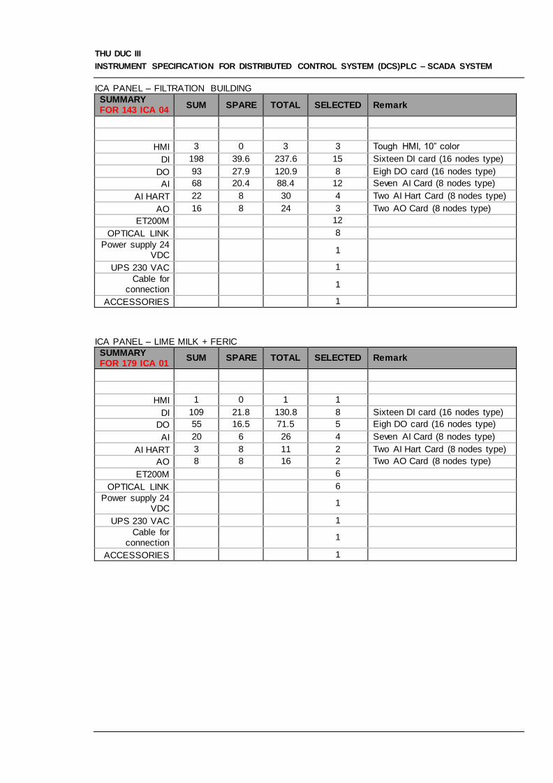
ICA PANEL – FILTRATION BUILDING
SUMMARY FOR 143 ICA 04
SUM SPARE TOTAL SELECTED Remark
HMI 3 0 3 3 Tough HMI, 10” color
DI 198 39.6 237.6 15 Sixteen DI card (16 nodes type)
DO 93 27.9 120.9 8 Eigh DO card (16 nodes type)
AI 68 20.4 88.4 12 Seven AI Card (8 nodes type)
AI HART 22 8 30 4 Two AI Hart Card (8 nodes type)
AO 16 8 24 3 Two AO Card (8 nodes type)
ET200M 12
OPTICAL LINK 8
Power supply 24 VDC
1
UPS 230 VAC 1
Cable for connection
1
ACCESSORIES 1
ICA PANEL – LIME MILK + FERIC
SUMMARY FOR 179 ICA 01
SUM SPARE TOTAL SELECTED Remark
HMI 1 0 1 1
DI 109 21.8 130.8 8 Sixteen DI card (16 nodes type)
DO 55 16.5 71.5 5 Eigh DO card (16 nodes type)
AI 20 6 26 4 Seven AI Card (8 nodes type)
AI HART 3 8 11 2 Two AI Hart Card (8 nodes type)
AO 8 8 16 2 Two AO Card (8 nodes type)
ET200M 6
OPTICAL LINK 6
Power supply 24 VDC
1
UPS 230 VAC 1
Cable for connection
1
ACCESSORIES 1

THU DUC III
INSTRUMENT SPECIFICATION FOR DISTRIBUTED CONTROL SYSTEM (DCS)PLC – SCADA SYSTEM
ICA PANEL – SLUDGE DEWATERING BUILDING
SUMMARY FOR 181 ICA 07
SUM SPARE TOTAL SELECTED Remark
HMI 1
DI 2 Sixteen DI card (16 nodes type)
DO 1 Eigh DO card (16 nodes type)
AI 1 Seven AI Card (8 nodes type)
AI HART 1 Two AI Hart Card (8 nodes type)
AO Two AO Card (8 nodes type)
ET200M 2
OPTICAL LINK 4
Power supply 24 VDC
1
UPS 230 VAC 1
Cable for connection
1
ACCESSORIES 1
1.2 Scope of Specification
This document defines the minimum requirements for design, materials, fabrication, configuration,
inspection, testing and painting for the Supervisory Control and Data Acquisition hereafter in this
document referred to as the SCADA, to be installed as part of the THU DUC III Project.
The supplier should draw upon his existing, pre engineered or standard designs to saisfy the
requirements on the basis of scope of supply, P&ID, layout and block diagrams.
1.3 Description of Plant
1.3.1 Thu Duc III Project Control Philosophy
This section provides an overview of the Control Philosophy to assist the Vendor in assessing the
requirements of this functional specification.
The Thu Duc III Project is a new phase, is designed to be able to process 300,000 water m3/day. Beside
that, the system is also designed to connectable to next phase. As such there is a requirement for a
process control system, and in compliance with various international codes and standards, a
functionally segregated Safety Shutdown System. All of these systems will be new and stand alone at
Thu Duc. There are, however, required interfaces between phase III and Phase IV which are discussed
later in this document.
SCADA is used for controlling, monitoring and collecting data for all devices in factory via controlling
screen with command buttons, data box, etc. After that, system sends controlling signals to PLC. Signal
processing programs in PLC will process received signal and generate commands to control devices. In
return, PLC will send back status signal as well as value (analog) of device’s operating parameters to
display in the user interface.
1.3.2 Extent of Automation & Control

THU DUC III
INSTRUMENT SPECIFICATION FOR DISTRIBUTED CONTROL SYSTEM (DCS)PLC – SCADA SYSTEM
The extent of automation and or remote control of the plant shall be as follows:
Thu Duc III Project Plant HMI shall be centralised, in the existing CCR.
Equipment used in the control or safeguarding of the plant shall be connected to the SCADA, ESD or
F&G systems as appropriate, and monitored / controlled using the SCADA HMI. In addition, matrix
panels are provided for critical HMI to ESD & F&G.
Start-up and shutdown of the plant will be largely automatic, although equipment requiring visual/local
checking will still require manual operator intervention at stages in the start up sequence. Normal plant
operation in the steady state shall be completely automatic.
Water quality, process and power system will be fully monitored on HMI in the CCR.
1.4 Scope of Supply
A standalone SCADA is required in the following locations:
- Thu Duc Water Treatment Plant
- Hoa An Pumping Station
The SCADA shall consist of a complete factory assembled unit. The unit shall be configured for Process
Control, and monitoring of all THU DUC III defined in this specification document and in the list of
referenced documents herein.
The Process Control I/O summary referenced in the Instrument I/O List, 815.301.PRxxx provides an I/O
count estimate and shall be used in conjunction with P&ID as the basis for sizing the THU DUC III
SCADA system.
The Vendor shall furnish all components and ancillary equipment necessary to make the SCADA
package complete, safe and ready for trouble free operation.
Each unit shall be complete with, but not limited to the following equipment and requirements
Main supply list at Thu Duc:
Operator interface workstations, each consisting of a 21“ Flat Screen LCD colour monitor,
membrane keyboard and Vendors standard VDU interface device, the preferred screen pointing
device is a trackball, the Vendor may offer an equivalent for the Purchasers approval. HMI Touch
Screen interface technology shall be used.
One (1) lot SCADA system and marshalling cabinets complete with controllers, I/O card,
Communication card and communication network units, power supply modules, terminal blocks,
Optical link modules, etc.
Two redundancy PLC S7-410H or equivalent at CCR are connected ot OS Servers via Industrial
Ethernet.
One (1) unit colour laser jet printers (A4 and A3 size) –nominally for printing alarms and printing
reports & graphics dumps.
Two (2) OS server with backup system completed with all required application software. The
server shall be provided with RAID 5 (Hard disk redundancy) configuration.
UPS 230VAC, 20A for each ICA panels;
One (1) Destop Engineering Workstation completed with all required software and application
programs – at Central Control Room (CCR)

THU DUC III
INSTRUMENT SPECIFICATION FOR DISTRIBUTED CONTROL SYSTEM (DCS)PLC – SCADA SYSTEM
Two (2) Destop Operator Interface Station completed with all required software and application
programs - at Central Control Room (CCR)
One (1) Destop for camera control completed with all required software and application programs
at Central Control Room (CCR)
One (1) Historian server and one (1) Webserver.
One (1) lot routers/FOs converter (support VPN with static IP address to connect to Hoa An
Pumping Station) and Industry Ethernet Switches/Hub;
One (1) lot of GPRS module.
One (1) lot cables (system cables, optical fibre cable, profibus dp cable, Ethernet CAT6 cable,
printer cable
Full package for accessories
List of Instrument Control Automation (ICA) panel:
- Equipment/componet at CCR (admin room)
- 801 - ICA – 01: Electrical room WTP
- 151.1 - ICA – 01: LME 1+2;
- 151.3 – ICA – 01: LME 3+4;
- 151.5 – ICA – 01: LME 5+6;
- 143 – ICA – 01: Filtration Building;
- 179 – ICA – 01: Feric + Lime Milk
- 802 – ICA – 01: CWPS
Main supply list at HOA AN:
One (1) lot SCADA system and marshalling cabinets complete with controllers, I/O card,
Communication card and communication network units, power supply modules, terminal blocks,
Optical link modules, etc.
Two redundancy PLC S7-300 or equivalent at RWPS are connected ot OS Servers via Industrial
Ethernet.
One (1) unit colour laser jet printers (A4 and A3 size) –nominally for printing alarms and printing
reports & graphics dumps.
UPS 230VAC, 20A for each ICA panels;
One (1) Destop Engineering Workstation completed with all required software and application
programs
One (1) Destop Operator Interface Station completed with all required software and application
programs
One (1) Destop for camera control completed with all required software and application programs
at Central Control Room (CCR)
One (1) lot routers/FOs converter (support VPN with static IP address to connect to Thu Duc) and
Industry Ethernet Switches/Hub;
One (1) lot of GPRS module.
One (1) lot cables (system cables, optical fibre cable, profibus dp cable, Ethernet CAT6 cable,
printer cable
Full package for accessories
List of Instrument Control Automation (ICA) panel:

THU DUC III
INSTRUMENT SPECIFICATION FOR DISTRIBUTED CONTROL SYSTEM (DCS)PLC – SCADA SYSTEM
- 800 – ICA – 01: RWPS
Other:
- Equipment/componet at CCR (admin room)
Process Control System Marshalling Cabinets for field cabling terminations, patch wiring,
termination boards and associated electronic components.
Communication bus, and serial data link interface equipment, modems, etc for interconnection to other systems
System software and licences as required for full functional operation of the process control system.
Application software including configuration and programming services as required for full
functional operation of the process control system.
HMI graphics development / testing, including ESD / F&G logic HMI graphics
Project Management, Engineering, Consultation & Programming Services.
All Hardware required interfacing between the component parts of the SCADA system and third
party interfaces detailed in this document.
All operating system, application and software licensing as called for by this specific ation. This
shall be the latest revision of all proprietary software. In addition, the Vendor shall include any
and all software revisions and manual upgrades which may be released for a period of two (2)
years after purchase order award.
All cabling between SCADA system components.
Engineering configuration services. The configuration activity shall be executed in the Vendor’s
premises using the Vendor’s configuration tools and assisted as necessary by the Purchaser.
Engineering design services and provision for testing for joint development of interfaces to 3rd
party systems, as listed in this specification, including ergonomic input to the design of both the
operator station furniture and the human machine interface.
Fabrication design services.
All testing services including the Vendor’s Factory Acceptance Test, System Integration Tests,
Site Acceptance Test. The integration tests where possible will be coordinated with the delivery of
packaged sub-system equipment in order to verify the correct operation of all interfaces without
the requirement for simulation.
Server, hub/switch for SCADA system as indicated in this document and “PLC AND SCADA
OVERVIEW”, 815.301.PR.941.E.011.00.
Terminal Administration System (TAS) - software for management system.
Verified and checked Equipment layout in control room.
Transportation of equipment to the site, unloading and storage.
Calculated the actual power consumption and power distribution
System integration specifications for all serial interfaces with peripheral equipment as listed in this
specification. This shall be the responsibility of the SCADA vendor to jointly develop the interface
specifications with 3rd party vendors.
Documentation
Special Tools
Preservation and packing of the SCADA in readiness for shipment to the site. The point of
demarcation between the Vendor’s and the Purchaser’s responsibilities will be after packing and
loading onto transport after the staging tests at the Vendor’s premises.
Training

THU DUC III
INSTRUMENT SPECIFICATION FOR DISTRIBUTED CONTROL SYSTEM (DCS)PLC – SCADA SYSTEM
Laptop PC and all operating and application software and licences for configuration and
diagnostics of subsystems etc during commissioning.
Recommended spares for start up, commissioning and two (2) years operation.
Optional rates for site support
1.4.1 Work Excluded
The Purchaser will provide the following:
VENDOR’s scope shall be as minimum include design, engineering, perform system
configuration, manufacture, fabricate, assemble, test, supply and deliver the complete system,
installation and connection, calibration, precommissioning and commissioning.
Installation of all SCADA equipment in the site.
Connect to all low voltage control panel (MCC) to send/receive command/signal, data.
Connect to all medium voltage switch gear to send/receive command/signal, data.
Connect to all instrument such as flow meter, pressure transmitter, temperature transmitter, pH
sensor, Turbidity sensors, switches, control unit, protection unit to receive the signal and data.
All field equipment, including cabling beyond marshalling cabinets.
Documentation required to enable the Vendor to proceed with the project requirements.

THU DUC III
INSTRUMENT SPECIFICATION FOR DISTRIBUTED CONTROL SYSTEM (DCS)PLC – SCADA SYSTEM
1.5 Project Specifications
Equipment shall be designed and installed in accordance with the latest edition of the following project
specifications:
Project Documents
Consumer List Including I/O for electrical, Instrument and
measurement
PLC and SCADA Overview
Process xxxx
1.6 Definitions & Abbreviat ions
Definitions
Certifying Authority Nominated Third Party Verifying Body
Company PASSAVANT ENERGY AND ENVIRONMENT
Inspector Nominated Third Party Inspection Agency
Project Data Sheets Governing technical documents for the specific item(s)
Project Drawings Reference drawings for the specific item(s)
Purchaser SWIC
Vendor Vendor of Equipment, including Sub-Vendors(s) appointed by the Vendor to
carry out part or all the work

THU DUC III
INSTRUMENT SPECIFICATION FOR DISTRIBUTED CONTROL SYSTEM (DCS)PLC – SCADA SYSTEM
Abbreviations
CCR Central Control Room
CED’s Cause and Effect Diagrams
SCADA Distributed Control System
DDFS Detail Design Functional Specification (Vendor deliverable)
DFS Design Functional Specification (Purchaser deliverable)
EPC Engineer, Procure and Construct (form of contract)
ESD Emergency Shutdown System
F&G Fire and Gas
HART Highway Addressable Remote Transducers
HAZOP Hazard and Operability Analysis
HMI Human Machine Interface
HSE Health Safety and Environment
IS Intrinsically Safe
ITP Inspection and Test Plan
OPC Object linking and embedding (OLE) for Process Control
OS Operator Station
P&ID Process & Instrumentation Diagram
PLC Programmable Logic Controller
RTU Remote Terminal Unit (telemetry outstation)
SCADA Supervisory Control And Data Acquisition
SIL Safety Integrity Level as defined by standard IEC 61508
SUB Start Up Bypass
TCP/IP Transmission Control Protocol / Internet Protocol
TUV Technische Überwachungs-Verein - a German based international standards authority
UCP Unit Control Panel
UPS Uninterruptible Power Supply
VDRL Vendor Data Requirements List
1.7 Vendor Exceptions
The Vendor shall be responsible to submit, together with the Tender, a list of deviations or exceptions to
this Specification. In the absence of any exceptions, it will be construed that the Vendor fully complies
with this Specification.

THU DUC III
INSTRUMENT SPECIFICATION FOR DISTRIBUTED CONTROL SYSTEM (DCS)PLC – SCADA SYSTEM
1.8 Order of Precedence
In the event of any conflict arising between this Specification and other documents listed herein, refer
comments to the Purchaser for clarification before design or fabrication commences. The order of
precedence that applies is as follows:
1. Purchase Order and Purchase Requisition
2. Project Data Sheets
3. This Specification
4. Project Drawings
5. Project Specifications
6. International Codes and Standards
1.9 Language
All documentation and communications shall be in the English language.

THU DUC III
INSTRUMENT SPECIFICATION FOR DISTRIBUTED CONTROL SYSTEM (DCS)PLC – SCADA SYSTEM
2. REGULATIO NS, CODES & STAND ARD S
2.1 Codes and Standards
All equipment shall be in accordance with the latest edition of the following codes and standards:
Vietnamese Codes and Standards
TCVN 5334 Electrical apparatus for petroleum and petroleum products terminal.
Requirements on safety in design, installation and operation
TCVN 3254 Fire safety-General Requirements
TCVN 3255 Explosion safety-General Requirements
TCVN 5738 Fire detection and alarm systems-Technical Requirements
TCVN 5760 Fire Extinguishing Systems-General Requirements for Design,
Installation and Use
American Gas Association
AGA Report No. 8, 1994
Compressibility and Super-Compressibility for Natural Gas and
Other Hydrocarbon Gases
American Petroleum Institute (API)
API RP 551 1993 Process Measurement Instrumentation
API RP 552 1st Ed,
Oct 1994
Transmission Systems
API RP 554 1st Ed,
Sept 1995
Process Instrumentation & Control
CENELEC – Centre for European Normalisation
EN 54 Fire detection and fire alarm systems
The Instrumentation, Systems and Automation Society (ISA)
ISA S5.1 July 1992 Instrument Symbols and Identification
ISA S51.1 May 1993 Process Instrumentation Terminology
International Standards Organisation (ISO)
ISO 9001 3rd Ed,
2000
Quality Management Systems – Requirements
International Electrotechnical Commission (IEC)
IEC 61000 6-2 Ed 1.0 b
(1999)
Electromagnetic Compatibility (EMC) – General Standard –
Immunity for Industrial Environments
IEC 60079-0 Ed 3.1 B Electrical Apparatus for Potentially Explosive Atmospheres – Part 0

THU DUC III
INSTRUMENT SPECIFICATION FOR DISTRIBUTED CONTROL SYSTEM (DCS)PLC – SCADA SYSTEM
(2000) General Requirements
IEC 60079-1 Ed 4.0 E
(2001)
Electrical Apparatus for Potentially Explosive Atmospheres – Part 1
Flameproof Enclosures ‘d’.
IEC 60079-11 Ed 4.0 b
(1999)
Electrical Apparatus for Potentially Explosive Atmospheres – Part
11 Intrinsic Safety ‘i’.
IEC 60947-5-6 1999 Low Voltage Switchgear and Control Gear Part 5-6: Control
Devices and Switching Elements – DC Interface for Proximity
Sensors and Switching Amplifiers (NAMUR) First Edition.
IEC 60331 Ed. 1b Tests for Electric cables under Fire Conditions (Fire Resistant
cables)
IEC 60332-3 2000 Tests on Electric Cables Under Fire Conditions - Test for Vertical
Flame Spread
IEC 60529 Ed 2.1 B
(2001)
Classification of Degrees of Protection Provided by Enclosures (IP
code)
IEC 61131 Programmable Controllers
Health and Safety Executive
89/391/EEC Display Screen Equipment Regulations 1992
Institute of Petroleum
IP-15, 2nd Ed., 1990 Model code of Safe Practice Part 15: Area Classification Code for
Petroleum Installations
National Fire Protection Authority (NFPA)
NFPA 72 National Fire Alarm Code
2.2 Regulations
All equipment shall comply with the relevant Vietnamese and international recommendations, and
relevant codes and standards. The Vendor shall determine what equipment requires type approval by
the local Vietnamese Authority and shall provide type approval equipment where necessary.

THU DUC III
INSTRUMENT SPECIFICATION FOR DISTRIBUTED CONTROL SYSTEM (DCS)PLC – SCADA SYSTEM
3. GENERAL REQUIREMENTS
3.1 Operation & Design Life
The SCADA shall be designed for minimum life duration of 30 years.
3.2 Environme ntal Conditions
The SCADA will be installed on THU DUC III Project.
The SCADA shall be designed suitable for the site conditions:
Maximum Temp: 40C
Minimum Temp: 13.8C
Annual Average: 27.2C
Maximum Humidity: 87%
Height relative to MSL: <1000m
Maximum Wind speed: 20m/s
3.3 Utility Data
The following electrical power supplies and instrument air system shall be made available for use by the
Vendor.
Normal Power supplies: 400 V AC, three phase 4 wire, 50 Hz - solidly earthed
230 V AC, single phase 2 wire, 50 Hz
UPS Power supplies: 230 V AC, single phase 2 wire, 50 Hz (1)
24 V DC (Loop power for instruments only)
Instrument air: Operating min / norm / max: 5 / 10.0 / 13.0 barg
Design max: 14.3 barg
Note (1) Voltage should be updated to the latest electrical specification and finalized in
detail design
3.4 Materials
All materials shall be as detailed on the Project datasheets and referenced specifications. When
materials are not specified the Vendor may offer his standard material suitable for the environment and
operating/design conditions.
All materials shall be new and free of defects.
The Vendor shall use only non-asbestos products.
3.5 HSE Requirements
3.5.1 Noise Limits
Maximum noise emissions shall be in accordance with Vietnamese legislation, Noise in Public and
Residential Areas, Standards for (TCVN 5949).

THU DUC III
INSTRUMENT SPECIFICATION FOR DISTRIBUTED CONTROL SYSTEM (DCS)PLC – SCADA SYSTEM
The design of the facility shall minimise the noise levels to the lowest practicable. Maximum noise level s
for external areas shall be 85 dB (A) measured at 1m.
The equipment located within instrument rooms shall not generate a noise level exceeding 45 dB (A) at
1m, laterally, from the source and 1.5m, vertically, from the floor.
3.5.2 Emission Limits
Instrument design shall minimise fugitive emissions.
3.6 Hazardous Area/IP Rating
All equipment shall be suitable for the Hazardous Area and Ingress Protection Rating as detailed below:
Non Hazardous Area – Indoor : IP42
All SCADA equipment for THU DUC III Refrigerated Storage Project will be installed in non-hazardous,
air conditioned, and indoor locations.
3.7 Transportat ion Loads
The SCADA shall be designed to withstand both dynamic and static loading and transportation
accelerations.
If required the Vendor shall provide transportation supports for loading and transporting the assembled
and completed packages from Vendors works by either road and/or sea.
3.8 Certifying Authori ty
The Purchaser shall ensure that all applicable technical, documentation or inspection requirements
specified by the Certifying Authority are included in this Specification or associated Project Data Sheets.
Equipment shall be certified to CENELEC or IEC standards only.

THU DUC III
INSTRUMENT SPECIFICATION FOR DISTRIBUTED CONTROL SYSTEM (DCS)PLC – SCADA SYSTEM
3.9 Units of Measurement
The units of measurement on all documentation and equipment shall be in accordance with SI Units of
Measurement.
Variable Symbol Unit
Temperature 0C Degree Celsius
Pressure Bar Bar
Vacuum kPaa Kilopascals absolute
Weight (mass) Kg Kilograms
Volume (liquid) m3 Cubic meters
Volume (gases) Sm3 Standard cubic meters
Flow (liquid) m3/h Cubic meters per hour
Flow (gas) sm3/d Standard cubic meters per day
Heat kJ Kilojoules
Power kW Kilowatts
Viscosity cP Centipoises
Heat Transfer
coefficient kJ/m2.oCh Kilojoules per square meter per degree Celsius per hour
Dimensions mm Millimetres
Level (storage) mm Millimetres
Level (miscellaneous) 0-100% Percent
Velocity m/s Meters per second

THU DUC III
INSTRUMENT SPECIFICATION FOR DISTRIBUTED CONTROL SYSTEM (DCS)PLC – SCADA SYSTEM
4. TECHNICAL REQUIREMENTS
SCADA should have following main functions:
- Monitoring and Controlling: user interface will display technological screen for arranging devices in the
factory. On these screens, device’s real status and analog value, e.g. pressure, flow, temperature,
current, etc, will be displayed. In addition, there are command buttons, parameter board for operator to
enter controlling parameters and send commands.
- Connecting to datalogger
- Connecting to power meter by ProfiBus/ Modbus protocol.
- Accessible via Web.
- Able to warn system administrator and higher management level via SMS.
- Providing central database and single station’s database. All data must be accurately synchronized
about time as well as value. Data is not lost when ADSL/GPRS connection is down.
- Easy to backup and restore.
- Flexible and expandable.
- Distributed Client Server
- Support many connecting protocols (connect to many types of PLC as well as devices) following
industrial standard OPC.
- Support charts as SPC chart, XY chart, etc.
- Suport timing chart and configuration user defines
- Support tags such as Event, Alarm Calculation, etc. Easy to calculate and set up PID on Scada
without accessing to PLC (to avoid dependence on the Contractor).
- Database of Scada must be able to import, export and query easily. It also has independent user
interface.
- Can cretate and change tag online without affecting system.
- Database must support communication among nodes and can be easy and
independently developed.
- Alarm event trend will be stored by file for easily backup and restore. There is no limit of time to store
alarm event as well data.
- Alarm must support many speed level (>7 levels). Alarm and event must define directly on tag
definition.
- Support VBA in each object on picture as well as global function.
- Suppport win vista 2008 server, win 2003 server.
- Support tag group for easy maintance.
- Support connection to many servers and clients (256 nodes)

THU DUC III
INSTRUMENT SPECIFICATION FOR DISTRIBUTED CONTROL SYSTEM (DCS)PLC – SCADA SYSTEM
- Database of Scada must be able to connect with other system such as wheatstone bridge, cameras,
fire-fighting system, sound system, etc.
- Scada in Hoa An and central Scada in Thu Duc must support exchanging data.
- Support security mode 21CFR11 for digital signature to use in the future.
- Easy to connect to other databases via ODBC or OLE DB.
- Can support 256 servers/clients for developing in the future and exchanging data with water factories
and branches in the city.
- Easy to upgrade into new version in the future but still be compatible with old version.
- Graphic supports multi-layer, allows people to view in detail for complicated picture (Graphic has layer
function).
- No limit on number of picture.
- Support security and assigning user.
- Support playback function (simulate device’s timing activities for system’s maintance and
troubleshooting)
- Support creating specific tags of process.
- Configuration of Scada system in Thu Duc and Hoa An: follow attached configuration table.
- Warning and error: alarm screens have display functions of error status of devices, signals. Error
statuses are display in two different forms.
- Security function and right of system access
- Modifying online: Scada must have functions of modify program (online) when it is running without
interrupt producing process (devices don’t have to stop when modifying SCADA).
- Monitoring via internet based on Web browser foundation: Scada must have function of monitoring via
internet based on web browser foundation like directly monitoringin factories with roles which are
assigned in server for security.
- Characteristics and size of software:
Base Scada must have license. This software must be able to manage PLC of different developers.
Controlling (I/O) size of Scada including devices which are investigated in the investigating reports and
in article III: project implementing range of phase 1 and preparation for future development is 20%
12.2. Historian and analysis database
Database of Scada must meet following requirements:
- Be able to store in 20 years and this ability must be proved clearly.
- Storage data must support timestamp and quality to ensure system’s accuracy. Database must be
exclusive for industry and easy to use.
- Be able to connect to OSI_PI collector.
- Storing must support compressing.
- Be able to exchange data among servers.

THU DUC III
INSTRUMENT SPECIFICATION FOR DISTRIBUTED CONTROL SYSTEM (DCS)PLC – SCADA SYSTEM
- Scada’s computers in Thu Duc and Hoa An must have database and, at the same time, there is
another central database in Thu Duc for backup in case computers are down.
- When connection is lost and restored after a period of time, data in this period must be sent to central
node so that collecting data can happen continuously.
- Allow connecting excel directly to central database in order to easily access any data without
modifying scada (to avoid dependence on the Contractor)
- Provide tools such as calculating average, min – max, total, deviation, standard deviation, etc. so that
reporting can be done easier.
- Historican data must be stored into files. These files are easily back up and restored.
- Support collecting data from csv, xml, data logger.
- Support collecting alarm and event.
- Suport saving (at least 20000 record/s).
- Suport digital signature 21CFR11.
- Support collecting, calculating for server.
- Support collecting data from Scada as well as other system in the future via OPC.
- Suport collection time to 1ms.
- Suport collecting, sending data from nodes to central database to synchronize data among nodes and
central node (especially 64-bit data).
- Support synchronizing time among data in nodes.
- Support data scaling and calculation
- Support data analysis.
12.3. Web:
WEB of Scada must meet following requirements:
- Web must be able to inherit Scada for easy modifying (copy data from Scada to web easily).
- Support at least 5 users connecting at the same time.
12.4. Sms:
SMS of Scada must meet following requirements:
- Support group alarm
- Define group user and priority
- Suppport working schedule
- Allow defining delay time.
12.5. Requirements of newly installed plc:
- Have redundance function for further upgrade in the future.
- Have Ethernet port and easily transmit data to Scada.
THU DUC III
INSTRUMENT SPECIFICATION FOR DISTRIBUTED CONTROL SYSTEM (DCS)PLC – SCADA SYSTEM
- Programming language follows IEC 1131 standard.
- Boolean calculation speed is at least 0.15ms/k.
- Minimum logic memory is 10MB.
- Realtime clock.
- I/O is compatible with the attached I/O table, list number xxx
- Analog is compatible with the attached I/O table, list number xxxx
- Support Ram Flash
- Processor is at least 300Mhz
- Support communication standards such as Modbus, Profibux, EGD, Hart, SRTP
- Support programming language C.
12.6. Hardware
12.6.1. PLC network,…
Industrial Ethernet: standard network which is very popular in industry, has less responding time, is
expendable and highly stable with following
functions:
- PLC is connected as ring structure to guarantee that the network still work when there is one PLC
failed.
- Network is easily expanded by adding PLC.
- Network’s events are always checked regularly and alarmed when there is accidents such as cable
parting, PLC failure, etc.
- Can easily expand redundancy.
12.6.3. Transmitting system
Private internet channel or ADSL/GPRS with static IP address is used from Thu Duc Water Plant to Hoa
An Pumping Station
Requirements of system displaying standard: in the programming progress, the Contractor should give
common regulations – following consistent standards of Europe or US (depend on the Contractor and
the vigilance of the Investor) for alarm, alarm lamp, siren, color of operation level. For example: red –
run, green – stop, yellow – alarm, etc. Moreover, report and format will be provided by the Investor.
2. Technical solution
12.7. Solution:
Solution is designed following Redundancy PLC.
General map of SCADA system in Thu Duc Water Plant
12.8. Assessing the solution:

THU DUC III
INSTRUMENT SPECIFICATION FOR DISTRIBUTED CONTROL SYSTEM (DCS)PLC – SCADA SYSTEM
This solution meets requirements of the project’s scope table in the agreement about “Consulting,
investigating and implementing SCADA project in Thu Duc Water Plant”. The system is designed
without using Redundancy. However, Redundancy still can be installed in the future.
Therefore, this solution has following advantages:
- Meet financial requirements, can be easily upgraded with redundancy if needed.
- Have simple design, can connect to many devices: data logger, warning via mobile phone.
- Safety level of this system is high, can guarantee safe and continuous water supplying.
The solution that CATIC center proposes meets almost requirements of designing, maintaining, building
and expandability in the future.
12.9. Describe the solution
According to the investigation and technical requirements that are mentioned in previous articles, the
technical solution suits SCADA system of the existing factory and can be expanded in the future. The
SCADA system includes 2 main groups (from the left to the right on the attached drawing “WATER
SUPPLY SCADA CONFIGURATION”):
12.9.1. Central server system and nodes in Thu Duc Water Plant
Server is installed respective program:
- 02 sets of industrial switch: 1 for controlling department and administrating house which are connected
to each other via fiber cable system in the factory. In the other hand, 1 set for PLC.
- Central controlling department includes: 2 servers with backup system, 1 computer for database, 1
computer for web.
- 02 controllers include: 1 controller is put in central controlling house, 1 in
deposit tank. These set controls remote I/O as unit group as divided in configuration map. Controllers
are connected to SCADA system via industrial Ethernet.
- 01 router Internet (support VNP) to connect to Hoa An station and 1 router to transmit to headquarter.
- 01 internet line with static IP address.
- Printer to print reports and UPS for energy saving (quantity is listed in the estimation table).
- Communication method: monitor SCADA system via internet or LAN using web server with at least 5-
user license.
12.9.2. System in Hoa An pumping station
The system includes:
- 01 Controller receives signal of monitored and controlled devices.
- 01 router Inter to connect to Thu Duc Water Plant via Internet with static IP.
- 01 Internet line with static IP.
- 01 computer to data controlling and monitoring is put in administration department.
- 01 printer connected to server for printing reports and charts.
- Moreover, there should be a UPS for energy saving (quantity is listed in the estimation table)
THU DUC III
INSTRUMENT SPECIFICATION FOR DISTRIBUTED CONTROL SYSTEM (DCS)PLC – SCADA SYSTEM
12.10. Technical attribute of the design
Devices used for controlling system are designed following international standards.
12.10.1. PLC
- Can be upgraded with redundancy in the future.
- Have Ethernet port and transmit data to Scada easily.
- Programming language follows IEC 1131-3 standard.
- Boolean calculating speed is at least 0.15ms/k.
- Minimum logic memory 240kb.
- Have realtime clock.
- I/O is compatible with I/O table, list number P.1006-LT-0701-01 in investigation documents that are
approved by the Investor.
- Analog is compatible with I/O table, list number P.1006-LT-0701-01 in investigation documents that
are approved by the Investor.
- Support Ram Flash.
- CPU speed (Processor) at least 133 Mhz.
- Support communication standards Modbus, Profibus, EGD, Hart, SRTP.
- Ethernet module should build switch function in module.
- Support C.
12.10.2. Computer, Printer and accessories
- For CPU, the processor must be at least Core4 Duo with high speed. RAM and HDD capacity should
be high capacity (counted at the constructing time) to avoid being behind the times. There are also DVD
write drive and other peripheral devices.
- For monitor, 21” LCD is recommended. Moreover, there should be another
50” LCD monitor for observing. Computers in central department, operation department and Hoa An
pumping department should use dual display monitors.
- Laser parallel printer (color printing for charts, mono printint for reports): printing speed is at least 20
ppm.
- Switch, cable and cable contactors, LAN card, Industrial Ethernet card.
12.10.3. Electric cabinet, intermediate relay and accessories
- Electric Cabinet:Vietnamese design. Imported steel frames. Thickness depends on provider. Minimum
protection level IP54 satisfies following factors:
substituted. So the working life
can be longer and the system is more reliable.

THU DUC III
INSTRUMENT SPECIFICATION FOR DISTRIBUTED CONTROL SYSTEM (DCS)PLC – SCADA SYSTEM
-circuit current, power light, warning light.
equipped with switch to change mode
Local/Remote.
- Intermediate relay:
NC and NO.
12.10.4. Other additional materials
- A terminal connects the signal cable with domino: use European or Japanese type.
- Signal cable and controlling cable for controlling system in PLC cabinet.
- Screws, bolts, etc. use Vietnamese products
- Cable box in the controlling cabinet… use Vietnamese products.
12.10.5. Technical documents
- The Contractor must provide in English or Vietnamese technical documents which are supplied by the
producers. Main parameters must meet (or more)
requirements. Other things such as attributes, technical design and working principles of devices must
be described cleary in these documents.
- Provided programs must have license and must be fully transferred to the Investor.
12.10.6. Instructing, training and transferring technoloty
The Contractor must commit to organize activities of instructing, training and transferring technology for
the factory’s technical employees about the whole system after technical acceptance. The content must
at least include:
- Introduce about map and principles of the system.
- Introduce about communication network, SCADA program and programming tool PLC.
- Introduce configuration and method to connect to the sytem of PLC.
- Introduce program, monitor and operate in computers.
- Instruct to use and program the monitoring and controlling software in computers (the instructor must
have certification for instructing and training Scada from provider).
- Operating process of the system.
12.10.7. Warranty conditions and after-sale service

THU DUC III
INSTRUMENT SPECIFICATION FOR DISTRIBUTED CONTROL SYSTEM (DCS)PLC – SCADA SYSTEM
The warranty must be at leat 12 months since the construction is takingover and is brought into
operation. The warranty includes all errors of designing and devices, may not include errors of wrong
operating and other accidents (e.g. flood, natural calamity, etc.).
The Contractor is in charge of all expenses to repair and recover the construction that is still under
warranty.
SCADA FUNCTIONAL AND OPERATIONAL REQUIREMENT
No Location, Devices &
Requirement Monitoring
Mode Collecting
Mode Warning
Mode Controlling
Mode Note
Remark
A. HOA AN STATION
1 Raw Water Pumps
Start/Stop/Speed Command x
Running/Stopped Status x
Trip/Fault Status x x
Local/Remote Status x
Auto Transfer Pumps x x
Speed x x x
Temperature x x x
Pressure x x x
Vabration x x x
Current (A) x x x
Real Time x
2 Penstock
Close/Open/Stop Command x
Closed/Openned Status x
Local/Remote Status x
Fault/Trip Status x x
Current (A) x x
Real Time x
3 Air Compressor
On/Off Command x
Run/Stop status x
Fault/Trip Status x x
Auto Transfer x
4 Butterfly Valve
Close/Open/Stop Command x
Closed/Openned Status x
Local/Remote Status x
Fault/Trip Status x x
Current (A) x
Real Time x

THU DUC III
INSTRUMENT SPECIFICATION FOR DISTRIBUTED CONTROL SYSTEM (DCS)PLC – SCADA SYSTEM
5 MV Switch Gear Incomer
Incomer Open Command x
Incomer Close via ATS
Command x x x
Incomer Open/Close Status x x
Incomer Trip/Fault Status x x
Protection x x x
5 MV Switch Outgoing
Open/Close Command x
Open/Close Status x
Trip/Fault Status x x
Protection x
Inter Trip to downstream x x
Current (A) x
Real Time x
6 Measuring System
Voltage, Current, Frequency,
Cos ø, KWH, KVARh,… x x x
7 Transformer
Controlling On/Off x
Working condition and failure x x x
8 Sensors:
Flow, Temperature, Pressure,
Level, pH, Vibration, Turbidiry, Leakage, weigh, gas detector, smoke, fire.
x x x
9 Solenoid Valve
Open/Close Command x
Open/Close Status x
10 VCB, ACB, MCCB, CB
Open/Close Status x
11 Pumps, Fans
Open/Close Command x
Open/Close Status x
Trip/Fault Status x x x
B. THU DUC
12 Clear Water Pumps
Start/Stop/Speed Command x

THU DUC III
INSTRUMENT SPECIFICATION FOR DISTRIBUTED CONTROL SYSTEM (DCS)PLC – SCADA SYSTEM
Running/Stopped Status x x
Trip/Fault Status x x x
Local/Remote Status x x
Auto Transfer Pumps x x x
Temperature x x x
Pressure x x x
Vabration x x x
Current (A) x x x
Real Time x x
13 Penstock
Close/Open/Stop Command x
Closed/Openned Status x
Local/Remote Status x
Fault/Trip Status x x
Current (A) x x
Real Time x
14 Air Blower
On/Off Command x
Run/Stop status x
Fault/Trip Status x x
Auto Transfer x
Softstarte Start Command x
Softstarter bypassed Status x x
Local/Remote Status x x
15 Butterfly Valve
Close/Open/Stop Command x
Closed/Openned Status x
Local/Remote Status x
Fault/Trip Status x x
Current (A) x x
Real Time x x
16 MV Switch Gear Incomer
Incomer Open Command x
Incomer Close via ATS Command
x x x
Incomer Open/Close Status x x
Incomer Trip/Fault Status x x
Protection x x x
17 MV Switch Outgoing
Open/Close Command x
Open/Close Status x
Trip/Fault Status x x

THU DUC III
INSTRUMENT SPECIFICATION FOR DISTRIBUTED CONTROL SYSTEM (DCS)PLC – SCADA SYSTEM
Protection x x
Inter Trip to downstream x x
Current (A) x
Real Time x
18 Measuring System
Voltage, Current, Frequency,
Cos ø, KWH, KVARh,… x x x
19 Transformer
Controlling On/Off x
Working condition and failure x x x
20 Sensors:
Flow, Temperature, Pressure, Level, pH, Vibration, Turbidiry,
Leakage, weigh, gas detector, smoke, fire.
x x x
21 Solenoid Valve
Open/Close Command x
Open/Close Status x
22 VCB, ACB, MCCB, CB
Open/Close Status x x
Trip Status x x x
23 Sludge Pump
Open/Close/Speed Command x
Open/Close Status x x
Trip Status x x x
Local/Remote Status x x
Temperature x x x
Current (A) x x x
Real Time x
24 Mixer Chamber
Open/Close Command x
Open/Close Status x x
Trip Status x x x
Local/Remote Status x x
Temperature x x x
Current (A) x x x
Real Time x
25 Paddle Mixer Chamber

THU DUC III
INSTRUMENT SPECIFICATION FOR DISTRIBUTED CONTROL SYSTEM (DCS)PLC – SCADA SYSTEM
Open/Close/Speed Command x
Open/Close Status x x
Trip Status x x x
Local/Remote Status x x
Temperature x x x
Current (A) x x x
Real Time x
26 Schludge Scraper LME
Open/Close/Speed Command x
Open/Close Status x x
Trip Status x x x
Local/Remote Status x x
Current (A) x x x
Real Time x
Torque Switch x x x
27 AUMA
Open/Close/Stop Command x
Open/Close Status x x
Fault Status x x x
Local/Remote Status x x
Current (A) x x x
Real Time x
28 System of measuring at Lab’s Room
x x x
4.1 Statement of SCAD A Vendor’s Responsibi li t y
The Vendor shall supply a standard field-proven fully integrated SCADA. The Vendor shall supply the
latest release of all hardware and software applicable at the time of bid presentation, no obsolete or
superseded releases of hardware or software shall be offered.
The Vendor shall have responsibility for applying a professional engineering methodology to the design,
fabrication, testing, documentation and preparation for shipment of the SCADA. Configuration shall be
conducted as a joint exercise between the Vendor and the Purchaser. The Vendor shall supply
engineering documentation, which shall include appropriate SCADA input to the Purchaser’s loop
diagrams. The Vendor shall also be responsible for the integration of all peripheral equipment interfaced
with the SCADA as listed in this specification.
The Vendor shall ensure that maximum use is made of Standardised Fixed/Limited Variabilit y
Programme System software. The use of Full Variability Systems software should be minimised and
restricted to those cases where it is necessary to develop bespoke software for a particular application.

THU DUC III
INSTRUMENT SPECIFICATION FOR DISTRIBUTED CONTROL SYSTEM (DCS)PLC – SCADA SYSTEM
Where used, an established method for controlling and validating software development and
subsequent modification shall be available.
The Vendor shall be responsible for configuration of gateways, switches, nodes, routers and other
applicable network hardware and software configuration to establish the redundant Process Control
System communications bus.
The SCADA Vendor is responsible for total SCADA performance, including communications to foreign
interfaced systems.
The Vendor shall prepare detailed procedures for the installation of equipment and software at site
where applicable. These procedures shall include estimates of the time and resources required for
executing each operation and conforming to the Purchasers work-pack format.
The Vendor shall request, at the tender stage, any additional information he requires concerning
interfaces to foreign systems, in order to ensure complete and successful integration with the SCADA
The Purchaser’s approval of the manufacturer and model number of equipment and approval of the
Vendor’s drawings/documents does not in any way affect the Vendor’s full responsibility to supply
strictly in accordance with project specifications, codes and standards.
This specification shall not relieve the Vendor of any responsibility to provide equipment and services
that are suitable for the intended duty.
Verify the loop wiring diagram and design the whole loop wiring diagram from field instruments to
marshalling cabinet (SCADA system).

THU DUC III
INSTRUMENT SPECIFICATION FOR DISTRIBUTED CONTROL SYSTEM (DCS)PLC – SCADA SYSTEM
4.2 SCAD A System Topology
The SCADA system design topology selected consists of an I/O sub-system and data processing
equipment, located in the Instrument room.
All field I/O shall be hardwired via junction/marshalling boxes to the Instrument room.
System hardware will be optimised by process units, reducing the potential for impact of any hardware
failures on production.
For a more detailed description of the SCADA topology selected the Vendor is referred to, XXX
The normal operation for THU DUC III Project control shall be centralised from the SCADA operator
interface stations located in the CCR.
All SCADA operator interface stations shall be configured to boot-up into ‘viewer’ privilege mode on
power up, and default from any higher security privilege level to ‘viewer only’ mode when the operator
interface station remains unused for a period of >20 minutes.
.
4.3 Instrument Syste m Interfaces
4.3.1 SCADA, ESD and F&G Interface Philosophy
The SCADA, ESD and FGS shall be designed to operate on a stand-alone basis.
The ESD/F&G operator interface station shall be capable of providing display and control functionality of
the ESD/F&G system.
In the event of a ESD/F&G operator interface station failure or for performing particular high integrity
tasks, hard wired console mounted ESD & F&G Matrix Panels, situated in the CCR, will be used to
monitor and control the ESD & F&G system. The ESD and F&G alarms shall be time stamped by the
ESD and F&G system prior to communication to the SOE and shall be printed on a process control
system printer.
The ESD/F&G systems will be capable of external bi-directional and redundant communication to the
SCADA Control Network.
The interface will use industrial and robust standard communication protocol. In case of failure of both
links and / or the SCADA, the ESD/F&G Systems shall not be affected and can run fully independently.
4.3.2 Existing SCADA System Integration
The SCADA system is connectable to any party to send/receive signal also connect able to next phase
4.3.3 Controlled Packages
The SCADA shall have the facility to interface with other sub-system microprocessor based PLC
systems or intelligent devices via single or redundant networks or serial data links. The SCADA shall
carry out control and monitoring of the package via a serial interface to the package local control panel.
The package unit field instruments shall interface directly to the local control panel control system.
The SCADA interface to the local control panel shall via a bi-directional serial interface.
THU DUC III
INSTRUMENT SPECIFICATION FOR DISTRIBUTED CONTROL SYSTEM (DCS)PLC – SCADA SYSTEM
The package Vendor, under the control of the Purchaser, shall be responsible for the specification of
the control functionality of the package. The SCADA Vendor shall be responsible for designing an
appropriate SCADA HMI user interface and for the joint development of the interface with the package
Vendor. Ultimate responsibility for the correct operation of the interface shall be with the SCADA Vendor
to ensure interface commonality and to optimise the data transfer between systems.
The required interfaces into sub-systems, and the required communication principles, are outlined in the
following sections.
4.3.4 MV-LV panel System Interface:
The SCADA shall have the facility to interface with all panel incl MV and LV panels System via serial
data links. The SCADA shall carry out monitoring some of equipment parameters specified by P&ID via
IP.
The MV-LV panel System Vendor, under the control of the Purchaser, shall be responsible for the
specification of the functionality of the MV-LV panel System that specified by P&ID. The SCADA Vendor
shall be responsible for designing an appropriate SCADA HMI user interface and for the joint
development of the interface with the Tanks Gauging System Vendor.
4.3.5 SCADA Emergency Shutdown and Fire & Gas Interface
The ESD / F&G systems shall interface to the SCADA system utilising redundant system
communications bus architectures.
This shall be achieved utilising separate dedicated redundant profibus network communications links
between the ESD / F&G and SCADA system.

THU DUC III
INSTRUMENT SPECIFICATION FOR DISTRIBUTED CONTROL SYSTEM (DCS)PLC – SCADA SYSTEM
4.3.6 Electrical System Interfaces
All status signals of the majority of electrical equipment at LV switch board is display on SCADA
operation station. Similarly, commands to start or stop drives operable by the Operator are transmitted
from the SCADA to the LV switch board.
Motors will be capable of being started and stopped from the SCADA Control Network to individual
motor control protection units. The SCADA will also receive status information about the motor from the
motor control protection unit. The control for small motors will be hardwire
Hardwired safety related trip signals to the individual motor control drives shall be generated from the
ESD/F&G system.
A subset of the total amount of detailed information available in the Electrical System is presented to the
Operator on the SCADA and will typically include only the following:
Drive Operation status (Running or Stopped)
Drive selected for remote operation (Remote or Local)
Drive fault status (Fault or Healthy, Trip)
Drive Commands from SCADA (Start, Stop,Speed)
Drive Operation time, Off time
Drive/Transformer temperature, Pressure;
Drive current, Voltage (receive signal from SIMOCODE, VFD, CT,VT);
Valve command from SCADA (Close, Open, Stop);
Valve status (Close, Open, Fault);
Temperatur, pH, Flow, Pressure, .. (Show on SCADA by table, Curve, export to print, excel,
picture file…)
For drives set-up as duty / standby pairs, a further control shall be provided within the SCADA
Drive Duty Selector (Duty, Standby)
This signal is used by the SCADA logic to determine the required action on failure of the duty pump.
On an individual basis, further data that may be required on SCADA will be identified and configured as
required.
4.3.7 Package Time Synchronisation
Larger Vendor packages will be equipped with their own control systems inclusive of alarming & HMI
functionality, the time stamping of which operates relative to their local clock. These external s ystems
may be interrogated to establish the cause of faults or shutdowns.
To allow an accurate comparison of alarm summaries from these packages with the main process
SCADA alarm summary, it is necessary to ensure that each package’s time of day is synchronised with
the SCADA time of day.
This synchronisation shall be achieved by the use of a hard-wired digital output. The outputs shall be
pulsed at predetermined times and the package UCP correct its internal time value based on this signal.
Only the minutes and seconds counters will normally require synchronisation.

THU DUC III
INSTRUMENT SPECIFICATION FOR DISTRIBUTED CONTROL SYSTEM (DCS)PLC – SCADA SYSTEM
4.4 SCAD A Hardware Design Requirements
4.4.1 System Design
The SCADA hardware system detailed design shall be carried out during the detail design stage by the
Purchaser.
For the purpose of the bid proposal the Vendor shall base the hardware design on the SCADA I/O
summary tabled in the Consumer List and PLC SCADA Review, P&ID and Electrical Drawings.
The Vendor shall take into consideration the following requirements when carrying out hardware system design.
Allocation of control functions shall be allocated within the system hardware with due regard to:
Processor & network loading
Plant integrity,
Common mode failure,
Cable marshalling,
Efficient use of equipment,
Segregation for maintenance,
Calculation of heat load and distribution,
4.4.2 System Redundancy
To provide a high level of integrity, the SCADA shall be implemented on a redundant basis. Thus all
main system components, including but not limited to, the system bus, microprocessor control units,
interface stations, network communications interfaces, gateways, routers, switches, multiplexers, power
supplies, and rack back-planes shall be segregated and duplicated by an on-line hot standby, which
maintain full control in the event of a failure. Transfer to the standby shall be automatic, shall be
alarmed and should have no effect on the operation of the control system.
The system shall be designed to ensure continuous operation with redundancy PLC controllers, two
CPUs on the same rack, in the event of a fault, changeover takes place from the master system to the
standby station. The method of event driven synchronization supports fast and bumpless changeover to
the redundant CPU in the event of a fault. It resumes processing at the point of interruption without any
loss of information or interrupts.
All components can be replaced during normal operation (Hot swapping). When a CPU is replaced, all
the current programs and data are automatically reloaded.
Central processing unit for the upper performance range of central and decentralized control, Used in
fault tolerant plants, programming using FBD, LAD, STL in accordance with IEC 61131-5, SCL, CFC,
GRAPH, Passward protection, supply voltage 24 VDC. Minimum work memory 1MB, support RAM and
EPROM external memory. Processing times for bit operation is at least 31.25 ns.
PLC must have at least 5 interfaces: (1) Ethernet/Profinet for programming, (2) Ethernet/Profinet
interface with 2 port switch for SCADA connection, (3) profibus interface for remote I/O,
(4&5)2xinterfaces for sync-modules.
4.4.3 Controller Processor Loading

THU DUC III
INSTRUMENT SPECIFICATION FOR DISTRIBUTED CONTROL SYSTEM (DCS)PLC – SCADA SYSTEM
The loading of the system processors shall not exceed 60%, including an allowance of 40% for the
installed spare capacity. The application software and firmware cycle times to meet this loading capacity
shall be set to ensure optimum control of all loops and fast process response (Refer to section 4.6.5 for
details).The system shall require a minimum of maintenance and shall have comprehensive watchdog,
self-checking and self-diagnostic fault detection capabilities, to monitor the system hardware and
software. System failures shall be reported as system alarms. The VENDOR shall provide details of the
redundant operating schemes and the consequences of loss of any functionality in back up mode.

THU DUC III
INSTRUMENT SPECIFICATION FOR DISTRIBUTED CONTROL SYSTEM (DCS)PLC – SCADA SYSTEM
4.4.4 I/O Capacity & I/O Spare
The capacity calculations of the SCADA I/O processor shall be based on the figures defined by the
SCADA I/O. In order to allow for expansion, the system shall have the minimum installed spare capacity
above the actual I/O and future allowance.
The capacity of the SCADA is defined by the SCADA I/O summary detailed in the “SCADA Instrument
I/O List” – document number: xxxx. With quantities tabulated separately for with, and without, spare
quantities. In order to allow for expansion, the system shall have a minimum of 20% installed spare
capacity above the actual I/O and future allowance defined in xxxx. This should include I/O facilities,
racks, power supplies and distribution, software and bus capacity. 50% spare capacity is required at all
entries into the cabinets and shall also be provided within the cable trunking.
Terminal rails shall be furnished with approved anti vibration screwed terminals. 30% spare installed
capacity shall be provided for each type of terminal fitting.
4.4.5 Hot Spare Capacity
The SCADA system shall be capable of supporting the installation of Hot Spares where specified by the
Purchaser. It shall be capable of enabling removal of installed hot spares from the equipment rack
without risk of adversely affecting adjacent equipment.
4.4.6 SCADA Server Specification
The exact hardware specifications for the engineering servers and clients shall be determined by the
Vendor during detailed design. This will minimise the risk of obsolescence in the rapidly changing
computer hardware technology field.
At the time of writing: The minimum hardware specification of the Engineering servers and workstations
shall be as follows:
Engineering Servers & Workstations
Intel @ Processor Minimum 3.5Ghz Processor.
2048 MB DDR SDRAM.
3MB/1GHz Cache
Automatic Server Recovery Function.
500 GB 10000RPM Hard Disk.
3.5" FD Drive.
8 X DVD +RW/+R Drive.
Dual Embedded Gigabit 10/100/1000 MHz Ethernet / NICs with Fail-Over & Load Balancing.
Keyboard & Cordless Mouse.

THU DUC III
INSTRUMENT SPECIFICATION FOR DISTRIBUTED CONTROL SYSTEM (DCS)PLC – SCADA SYSTEM
4.4.7 Human Machine Interface
OPERAT I NG CONSOL E S & PERIP H E RAL S
The operator console layout shall be reviewed and agreed with the Purchasers client operations team at
an early stage of console design, this practice helps to establish timely receipt of the clients preferred
layout and engenders client ownership of design minimising the risk of subsequent rework.
The preferred design shall be based around a curved console layout utilising a two tiers approach for
screen placement as this maximises the operator’s overview capabilities.
All Operator interface station hardware shall be mounted remotely from local Instrument room to
minimise noise and & heat in the Instrument room. The CCR console shall contain the OS display,
keyboard, CPU and pointing device.
The SCADA Vendor shall supply ergonomically designed transportable operator consoles as defined in
section 1.4 of this document - Scope of Supply, to house the operator interface station LCD monitors,
ancillary and communications equipment. The operator console design will also incorporate facilities for
seamless fitment of two matrix panels to house a dedicated ESD matrix and a dedicated F&G matrix
supplied by ESD/F&G vendor.
The design shall incorporate sufficient additional space for operator’s documentation along with a
suitable writing area.
The design of the operator console shall comply with the HSE Display Screen Equipment Regulations
1992 (EEC directive 89/391/EEC). Including:
Display screen with stable image, adjustable brightness and free of glare.
Minimisation of reflection, noise, heat and radiation.
Adequate lighting and humidity.
OPERAT OR D ISPLAY M ONITORS
The operator interface workstations as detailed in the scope of supply shall consist of 21” LCD Flat
Screen Monitor computer display devices, with a minimum resolution of 1280 x 1024 pixel matrix of 32
bit true colour.
KEYBOA R DS & POINTI NG DEV ICES
All keyboards shall be industrially hardened, and be impervious to ingress of dust, smoke and liquids.
Accidental depression or failure of a single key on any keyboard or trackball shall not cause a control
action to occur; control actions shall require a minimum of a two key sequence.
PRINT ER S
The SCADA shall perform day to day production reporting.
Two printers shall be supplied for alarm, event and report duties. Both printers shall be high resolution
colour laser type. One shall normally be configured to cover all alarm and event printing functions. One
shall normally be configured for printing reports, screen dumps etc. In the event of printer failure, either
printer should be able to be selected to take over the failed printers function.
The printer shall be connected to the Process Control System LAN and shall include a self-contained
print server for standalone operation. Sufficient memory shall be provided to support full page graphics
printing.

THU DUC III
INSTRUMENT SPECIFICATION FOR DISTRIBUTED CONTROL SYSTEM (DCS)PLC – SCADA SYSTEM
The printers shall have a maximum noise level of 48Dba at 1 metre; this may be achieved by the use of
acoustic hoods.
Colour Laser Printer Minimum Requirements:
Minimum Print Speed - 5 pages per minute.
Image captures time to be < 10 secs.
Print colours – choice of 256.
Print resolution > 1200DPI.
230V AC 50 Hz UPS supplies.
Supplied on mobile stand, with fresh and used paper storage facilities attached.
Provide as a minimum, On-line / Off-line / Paper Out / Print Job Failed fault diagnostic alarms to
SCADA.
A4 Stationary feed – 500 sheet magazines.
Self Test Facility.
SCADA communication to be via LAN connection
4.4.8 Change, Repair & Test On-Line
The SCADA hardware supplied must be capable of hot swappable change-out to facilitate on line
maintenance without disruption to any other system component or application.
The SCADA hardware supplied must be on-line addressable and configurable through the supplied
engineering workstation package without disruption to any other system component.
The SCADA hardware supplied must support on-line testing of the hardware through the supplied
engineering workstation package without disruption to any other system component.
4.5 Field Signal Characterist ics
4.5.1 Analogue to Digital Conversion
The ADC and DAC performed by the I/O cards shall meet the minimum requirements as specified
below:
Analogue-to-digital converter (ADC)
Resolution: 16 bits.
Linearity: ± 1 least significant bit (LSB).
Repeatability: ± ½ LSB.
Accuracy: ± 0.1% full scale over entire operating temperature range.
Common mode rejection @ 50Hz: 98dB
Digital-to-analogue converter (DAC)
Resolution: 16 bits.
Linearity: ± 1 LSB.
Repeatability: ± ½ LSB.
Accuracy: ± 0.25% full scale over entire operating temperature range.
THU DUC III
INSTRUMENT SPECIFICATION FOR DISTRIBUTED CONTROL SYSTEM (DCS)PLC – SCADA SYSTEM
All analogue I/O points shall be individually isolated and individually fused on the high (supply) side
through the use of fused terminals. The fuse rating for all analogue I/Os shall be 100 mA. Fuse health
shall be able to be monitored visually (e.g.: Socket Board LED indicators or pop-up tag type fuses).
The system shall be able to support HART communications on all analogue I/O points as standard.
All analogue I/O cards shall have an individual power regulator to provide isolated power for AO and
isolated transmitter power for AI (where the AI is system powered).
All calibration constants of the I/O card shall be handled using software without the need for any
potentiometers on the I/O card. As a result, replacement of an I/O card shall not require recalibration
4.5.2 Analogue Inputs
The SCADA shall support the following types of Analogue Input (AI)
The SCADA will be capable of interfacing to 2, 3, and 4 wire devices. The 24 VDC loop power for two
wire devices shall be supplied by the SCADA and the current shall be sourced by the SCADA. The 3
wire devices shall be supplied 24 VDC from the SCADA. The 4 -20 mA DC signal shall sink at the
SCADA. The device shall not be grounded.
In particular, 4-20 mA DC 2 wire transmitters supplied at 24VDC from the system and suitable for a
maximum input resistance of 250 ohms, with HART communication capabilities, both I.S and non I.S,
Individually fused. Where Hart devices are used the SCADA shall provide access to the full range of the
transmitter’s intelligence from the operator and/or engineering workstation.
Alarming of out of-range signals,
Dual Redundant Capable,
Selectable isolation from ground,
Intrinsically safe as standard,
Support “HART” protocol,
Common and differential mode surge protection,

THU DUC III
INSTRUMENT SPECIFICATION FOR DISTRIBUTED CONTROL SYSTEM (DCS)PLC – SCADA SYSTEM
4.5.3 Analogue Outputs
Alarming of open or short circuit loads,
Standard sourcing 4 -20 mA signal capable,
Supply of 24VDC power to the load (current limited),
Intrinsically safe as standard,
Support “HART” protocol,
Common and differential mode surge protection,
Dual Redundant Capable,
Capable of driving an output load of 1000 ohms (Non-I.S.) or 600 ohms (I.S.),
Capable of programmable selection of fail state action on communications failure,
4.5.4 Digital Inputs
The SCADA shall support the following types of Digital Inputs
All digital I/O points shall be individually isolated and fused. Fuses shall be able to be replacing without
removing the I/O card. All digital I/O cards shall provide loop status LED indication. Specifications on
digital I/O shall be as follows:
24VDC as input “1” (logical “true”) and open circuit as input “0” (logical “false”). The sense voltage to
field contacts shall be supplied from the SCADA via individually fused circuits.
Intrinsically safe as standard,
Dual Redundant Capable,
Incorporate surge protection,
Provide contact “de-bounce” circuitry,
4.5.5 Pulse Inputs
Suitable for 3 wire connection.
Compatible with a received signal that is square wave, unipolar, of 8-24 VDC peak magnitude, 10Hz -20
kHz frequency. Exact pulse rates and levels will be defined during detailed design.
Intrinsically safe as standard.
Incorporate surge protection.
4.5.6 Digital Outputs (24 VDC)
The SCADA shall support the following types of Digital Outputs
Dry contacts rated at 4A (24VDC). These shall be selectable as normally open or normally
closed, momentary or maintained. The voltage to outputs shall be supplied by the SCADA
(including individual fuse protection) for 24VDC outputs.
24VDC, I.S. powered digital outputs, 45ma load minimum, individually fused (with out the use of
interposing relays).
24Vdc, non-IS powered digital outputs, 1amp load minimum, individually fused (with out the use
of interposing relays).
Incorporate surge protection,

THU DUC III
INSTRUMENT SPECIFICATION FOR DISTRIBUTED CONTROL SYSTEM (DCS)PLC – SCADA SYSTEM
Capable of programmable selection of fail state action on communications failure,
Dual Redundant Capable,
4.5.7 Intrinsically Safe Circuits
The SCADA system shall support interface to intrinsically safe circuits through intrinsic safety isolation
achieved through the use of appropriately certified, galvanically isolating intrinsically safe interface units.
The barriers may be either inherent in the system I/O cards, termination assemblies or field cable
termination blocks within the marshalling cabinets.
The SCADA Vendors intrinsically safe equipment shall be capable of interfacing to high frequency pulse
transmission to enable connection of HART devices.
4.5.8 Smart Field Device Interfaces
The SCADA shall be capable of interfacing to the following smart device protocols to enable
interoperability and competitive selection of smart field devices.
The SCADA shall interface to all HART analogue transmitter inputs, HART multiplexers are not acceptable.
This will enable incorporation of HART parameters into the SCADA Asset and Maintenance Management
System.
4.6 Syste m Performance
4.6.1 Input Conditioning
The SCADA shall provide the capability to apply analogue input point, process variable filtering to
prevent signal noise degrading the system and communications performance. Filter time constants shall
be configurable from the SCADA engineering workstation on an individual input point basis.
4.6.2 System Diagnostics
The SCADA VENDOR shall state clearly the tools and methods available for system health monitoring,
system performance statistics and proactive failure analysis for all SCADA components.
The SCADA shall have extensive self diagnostic capabilities running on-line as a background function.
The SCADA shall generate alarms and log internal errors/faults to the system log files for archiving.
The SCADA shall provide graphic displays dedicated to providing diagnostic and system performance
overviews to enable clear identification of system component failures including both primary and backup
in the case of redundant nodes.
4.6.3 Controller Failure
The SCADA controllers provided must incorporate a designed inherent redundant architecture that
provides a demonstrable availability figure of > 99.99% in accordance with section 4.6.10. Redundancy
features shall include
Synchronous operation of redundant CPU’s,
Uninterruptible switching of control on master controller failure, (< 1ms),
Fault diagnostics generation & alarming on CPU failure.
4.6.4 SCADA Memory Retention

THU DUC III
INSTRUMENT SPECIFICATION FOR DISTRIBUTED CONTROL SYSTEM (DCS)PLC – SCADA SYSTEM
All SCADA devices or components containing volatile memory shall employ a means of battery back -up
in order to preserve memory contents for not less than 28 days subsequent to interruption of power to
the system, and so avoiding the need to re-load software.
The SCADA Vendor shall fully describe where all software resides in the system and identify where
volatile memory cannot be preserved for the specified time.
4.6.5 Processing and Scan Rates
CONTROL L ER ANALOG UE PERFORM A NC E
Controller analogue performance based on system execution speed, under the stated loading
conditions, shall facilitate loop execution speed as described below. Where execution speed refers to
the computation period for the cycle of reading all inputs, executing analogue algorithms and writing the
results should be referred to the analogue output registers.
Based on I/O loading of 100% actual I/O + spare requirements identified in section 4.4.4.
20% for 1.0 second updates
60% at 0.50 second updates
20% at 0.25 second updates
CONTROL L ER DIGITAL PERFORM A NC E
Controller digital performance based on system execution speed, under the stated loading conditions,
shall facilitate loop execution speed as described below. Where execution speed refers to the
computation period for the cycle of reading all inputs, executing digital algorithms and writing the results
should be referred to the output registers.
Based on I/O loading of 100% actual I/O + spare requirements defined in section 4.4.4. 100% for 200
ms updates
4.6.6 Operator Interface Station System Response Times
The SCADA operator interface station system response times detailed below shall be based on
manipulating the most complex graphic application available.
Graphic Displays 2 seconds
Alarm Annunciation 2 second
Graphic Display Dynamic Data Update 1 second
Alarm and event resolution 1 second
Sequence Of Events Resolution 1 millisecond
Response to Keyboard/Trackball Immediate
4.6.7 Loading
Loading of operator interface stations, controllers, data communications devices and networks shall not
exceed 60% of total capacity under maximum loading conditions including all spares capacity defined in
this document, maximum loading conditions is to be based on the heaviest alarm load possible.
The SCADA Vendor shall provide calculations for the estimation of the data loading for all
communications circuits, in his tender.
4.6.8 Alarm Flooding

THU DUC III
INSTRUMENT SPECIFICATION FOR DISTRIBUTED CONTROL SYSTEM (DCS)PLC – SCADA SYSTEM
The SCADA system shall provide inherent alarm handling capabilities to prevent/minimise alarm floods
on the SCADA. The alarm handling package shall be capable of automatically disabling alarm
annunciation both audible, and visual on the alarm summary displays under prescribed operating
conditions. The alarm handling package shall also support manual selection of alarm disabling by the
process operator. The disabled alarm states shall still be visible to the operator on the applicable
process graphic and be logged in the alarm/event log.
The alarm handling package should automatically identify the operating conditions to initiate alarm
disabling from a set of criteria based on measured operating parameters defined by the Purchaser in
the detailed design documentation.
4.6.9 SCADA System Re-Boot Time
The Vendor shall state and guarantee the time that the entire SCADA system, including all controllers,
servers, gateways, switches, hubs, interface stations, software applications, historizing & archiving
functions take to conclude their re-start routines and return to normal status.
This value is to be based on the actual system hardware and software proposed in the Vendors
proposal, not on a typical installation.
The figure guaranteed will be subject to verification during the FAT procedures.
4.6.10 Availability/Reliability Requirements
GENERAL
The SCADA System is required to have an overall availability of 99.99% or better with a Mean Time to
Repair (MTTR) of no more than one hour. The Vendor shall submit the availability calculation for the
system proposed along with the system reliability figures for all SCADA sub components. Equipment
reliability figures used in the calculations shall be based on proven field performance or similar
installations. The overall design of the system shall be such that the failure of any component of the
system shall have minimal affect on the process operation.
SYSTEM RELIABILI TY F IGURES
The reliability figures to be achieved by the system are summarized below:
MTBF : *
Minor Failure : *
Significant Failure : *
Major Failure : * > 10 Years
Total Failure : * > 50 Years
* Indicates value to be calculated by SCADA Vendor.
Data used in the calculations shall be supplied and the source of the data shall be identified. All
assumptions shall be clearly explained with justifications.
4.7 SCAD A Communicat ions
4.7.1 Data Communications
The control system network shall provide real time performance. The control system shall be based on
“open” system architecture and protocols. That is, the system shall have inherent capability to integrate

THU DUC III
INSTRUMENT SPECIFICATION FOR DISTRIBUTED CONTROL SYSTEM (DCS)PLC – SCADA SYSTEM
and exchange information with other brand system devices and platforms via industry standard
communications, platforms and protocols.
4.7.2 Gateways
The SCADA shall be capable of interfacing to third party systems via gateways. Where proposed by the
Vendor the gateways shall satisfy the following requirements:
Provide within the gateway a resident image table of all data blocks written to or read from this device,
such that the SCADA accesses only the image data so reducing downstream network congestion.
The gateway image table shall be updated asynchronously to SCADA operations with configurable
update times.
Provide error checking and diagnostics on data transfer.
Ability to assign tag names and descriptors to gateway addresses.
Provide translation of data protocols.
The Vendor shall fully describe the ability of the system proposed to integrate with the third party
systems detailed in section 4.3 and his methodology for doing so. The resulting inter-operability of the
SCADA with the third party packages shall be fully described.

THU DUC III
INSTRUMENT SPECIFICATION FOR DISTRIBUTED CONTROL SYSTEM (DCS)PLC – SCADA SYSTEM
4.7.3 Ethernet Interfaces
The SCADA shall provide as a minimum, Ethernet interface capability to the ProfiBus DP
4.7.4 Serial Interfaces
The SCADA shall provide as a minimum, /RS-485 Serial interface capability to the Modbus
RTU/ProfiBus DP.
4.7.5 Fibre Optic Links
The SCADA Vendor shall supply details of proposed fibre optic link interface devices required to
integrate the SCADA distributed control network
4.7.6 SCADA Network Loading
Loading of data communications devices and networks shall not exceed 60% of total capacity under
maximum loading conditions including all spares capacity defined in this document, maximum loading
conditions is to be based on the heaviest alarm load possible.
The SCADA Vendor shall provide calculations for the estimation of the data loading for all
communications circuits, in his tender.
4.7.7 Network Diagnostics
The SCADA Vendor shall state clearly the tools and methods available for sys tem health monitoring,
system performance statistics and proactive failure analysis.
The SCADA shall have extensive self diagnostic capabilities running on-line as a background function.
The SCADA shall generate alarms and log internal errors/faults to the system log files for archiving.
The SCADA shall provide graphic displays dedicated to providing diagnostic and system performance
overviews to enable clear identification of system component failures including both primary and backup
in the case of redundant nodes.
The SCADA shall display the number of re-tried transmissions resulting in non-fatal communications
errors to enable advance warning of network issues.
4.7.8 Network Error Handling
The SCADA Vendor shall state clearly the tools and methods utilised to manage transmission error
detection and elimination. These shall include but not be limited to:
Error checking on all transmissions.
Automatic re-transmission on error detection.
Automatic switching to standby data path in the event of primary link critical fault or failure.
4.8 SCAD A Software
4.8.1 General
The Vendor shall supply clarification of the standard system software release version that is proposed in
the bid, and his expected software updates for the coming 3 years. The migration path for future
software upgrades shall be clearly specified by the Vendor.

THU DUC III
INSTRUMENT SPECIFICATION FOR DISTRIBUTED CONTROL SYSTEM (DCS)PLC – SCADA SYSTEM
The SCADA Vendor shall provide as part of the system all system and application software (fully
configured & documented) necessary to implement the functionality described in this specification and
the Equipment Specification for SCADA Functional Requirements.
The software shall be designed and programmed to facilitate maintenance, modification and future
expansion of facilities and be of modular structure. For standard supervisory control, monitoring,
sequential and interlocking the software coding shall be provided through the Vendors standard function
block oriented application programming techniques.
Maximum use shall be made of standard application logic macros for all commonly used functional
requirements, this maximises programming efficiency allowing parallel manpower development, and
results in standardised application logic which simplifies operation, long term maintenance and
development requirements for the client.
Where the Vendor proposes the use of industry standard high level programming languages, eg
FORTRAN 90, PASCAL, VB, C/C++ to satisfy functional requirements the Vendor must submit in
advance of any programming being carried out his reasons for requesting this variation and request the
approval of the Purchaser.
4.8.2 Controller Functionality
The SCADA, as offered, shall utilise a single global distributed system database structure distributed to
the controller level. All algorithms, tags, loop descriptors, and calculated or actual values shall reside in
the controller card cage. All information in the controller, all digital and analogue data, whether it be field
or system calculated, all system alarms, and all diagnostic information shall be globally accessible by
every node on the SCADA Control Network.
The SCADA, as offered, shall accept and manipulate, as a minimum, sixteen character tags.
The SCADA Controllers shall be mounted in Instrument rooms and shall be fully pre-programmed with a
wide selection of control and data acquisition algorithms. Configuration shall be maintained in RAM (or
non volatile memory) and shall have battery power back up. In the event of a link failure between the
controlling device and the SCADA Control Network, the controller shall continue to monitor and control
the process without interruption.

THU DUC III
INSTRUMENT SPECIFICATION FOR DISTRIBUTED CONTROL SYSTEM (DCS)PLC – SCADA SYSTEM
4.8.3 System Functionality
REGUL AT OR Y CONTROL
The SCADA as offered shall provide as a minimum the following regulatory control functions:
PID control
Input Indication
Manual loaders
Signal selectors(High/middle/low)
Signal setters
Sequence Function Control (SFC)
Function Block Diagrams (FBD)
Structured Text (ST)
Batch Control
Controller Bump-less Transfer
Gap controller
Internal Cascade Control
Error squared controller
Integral with Bias Controller
Split Range Control
Lead Lag Function
Dead Time Compensation Function
Ratio/Bias Controller
Adaptive Control
Mass Flow Computation
Velocity Limiter Function
Rate of Change Calculation
User Selectable Math and Logic Functions
Piecewise Linear Interpolator
Discrete Motor Controller
Auto Sequencing Motor Controller
Dual Speed Motor Controller
Dual Direction Motor Controller
Discrete Valve Controller
Auto Sequencing Valve Controller
Motorised Valve Controller
Configured Moving Average
ADV ANC E D CONTROL
The SCADA as offered shall provide as a minimum the following advanced control functions:
Fuzzy Logic Controller
Multivariable Control
Neural Control

THU DUC III
INSTRUMENT SPECIFICATION FOR DISTRIBUTED CONTROL SYSTEM (DCS)PLC – SCADA SYSTEM
Multivariate Statistical Control
Real Time Optimization
Auto Self-Tuning controllers
4.8.4 Alarm Management
Process and system alarms shall be annunciated audibly and displayed at appropriate workstations.
They shall be printed on appropriate alarm printers and logged in alarm history files.
An audible signal shall sound each time an alarm occurs. A visual signal shall indicate plant section
in which the alarm has occurred. Audible sound shall have different, configurable, priority tone
levels.
It shall be possible to alarm any point in the system.
It shall be possible for an operator to acknowledge any alarm configured at his workstation by no
more than two actions. The operator shall be able to acknowledge a single alarm, a group of alarms
or all alarms on current page.
ALARM SUM M ARY D ISPLAY
It shall be possible to provide separate alarm summary displays for each plant section in the following
format:
Multi-page displays may be used for alarm summaries. It shall be possible to access these pages
sequentially (forward or backward) by a single operator action.
The alarm summary display shall list alarms in tabular format in order of occurrence with most
recent alarm at the top. An option shall be available to list alarms by priority with the highest priority
alarms starting at the top of the page.
Accessing alarm summary displays from any other display shall require no more than two operator
actions.
Alarm display format shall be one line of 80 characters minimum. The alarm message shall contain
the following information as a minimum:
1. Time of alarm in "hours:minutes:seconds" in a 24-hour format
2. Tag ID
3. Tag descriptor
4. Type of alarm
5. Engineering units
6. Alarm priority
7. Alarm limit and actual value or desired state and actual state
Colours for different alarm states shall be configurable for graphics.
PROC ES S ALARM ING TYPES
The following types of alarms shall be provided as a minimum:
Process input high/low warning value
THU DUC III
INSTRUMENT SPECIFICATION FOR DISTRIBUTED CONTROL SYSTEM (DCS)PLC – SCADA SYSTEM
Process input high/low absolute value
Process input excessive rate of change
Process input out of range high/low failure
Process input setpoint deviation from control and computational point high/low warning value
Process input setpoint deviation from control and computational point high/low absolute value
Process input high/low deadband deviation
Contact input change of state
PROC ES S ALARM LOGGI NG
For each process alarm that is configured to be logged, the alarm printer shall be activated
automatically upon any alarm condition.
Alarms shall be logged only on the alarm printer associated with workstations that are configured for the
plant section in which alarm occurred.
The following information shall be logged as a minimum:
Alarm tag ID
Alarm description
Type of alarm
Time of alarm, time acknowledged and time returned to no alarm expressed in
"hours:minutes:seconds" in a 24 hour format (day and month shall also be logged)
Process value at alarm
Alarm priority
Log entries shall be generated for tags going into alarm state and for tags returning to normal. Tags
going into alarm shall be indicated by red colour or by some other easily recognized characteristic. Tags
returning to normal shall be indicated by black colour or some other easily recognized charact eristic.
Alarm printer shall be the Laser type.
ALARM DEACTIV ATI ON AND INHIBI TI N G
It shall be possible to manually inhibit alarms on a point-by-point, group or system-wide basis. This
capability shall be protected by system access control. These actions shall be logged. A list of
suppressed alarms shall be available at the operator station.
An alarm cutout function shall be provided to automatically suppress alarms upon occurrence of
another alarm.
An alarm cutout function based on logic shall be provided to deactivate groups of alarms for
equipment that is out of service.
SYSTEM ALARM S
All devices connected to the communications network shall be monitored for failure.
An alarm indication shall be generated for each failure detected.

THU DUC III
INSTRUMENT SPECIFICATION FOR DISTRIBUTED CONTROL SYSTEM (DCS)PLC – SCADA SYSTEM
It shall be possible for system alarms to be logged on a printer separate from the process alarm
printer.
4.8.5 Historical Data and Trends
This Section details the minimum requirements for historical data collection, trending, event history and
sequence of events.
GENERAL
There shall be configurable real-time and historical data collection package to support trending.
It shall be possible:
For operators to trend tags as needed
To store the value of any analogue point or calculated value in history files
To record the change of state of any discrete point in one of the event histories

THU DUC III
INSTRUMENT SPECIFICATION FOR DISTRIBUTED CONTROL SYSTEM (DCS)PLC – SCADA SYSTEM
H ISTORI CA L DATA
The Operator system shall provide a complete historical subsystem providing the user the capability to
capture and analyse historical data. The system shall allow selection of any point in t he system to be
added and configured for archiving.
The archiving system shall ultilize a Microsoft SQL real time relational database for storage of all
process related data. Flat file or internal proprietary databases will not be accepted. The archiving
system shall be configured using standard tools provides by the system to facilitate the display and
editing of archive rates, archive types, etc. from graphical and tabular data displays.
The system shall support the online addition of new tags to the historical database without interrupting
operations.
The historical subsystem shall promote the visualization of historical data in both tabular and graphical
form. The historical system shall provide the ability to define archiving rates in increments of
millisecond, seconds, minutes, hours, or days. The historical system shall allow an individual archive
rate to be systematically modified and/or utilized as part of the control logic/Scripting requirements
specified above.
A high speed back up device with removable media, such as streaming tape cartridge or optical disk,
shall be provided for each, suitable for backing up the whole system on a weekly basis. At least one
double DVD write/rewrite/read with +R and –R capacity in addition to the historical data storage device
in the operator station should be provided.
It shall be possible to transfer data to removable media for historical data storage and/or archiving. The
historical device shall not support any type of data compression algorithm that is not 100 percent
recoverable. Following are minimum requirements for historical storage:
Eight hours of five second snapshots
Ninety-six hours of one minute snapshots
Hourly averages for last 168 hours
Eight hour averages for last 168 hours
Daily averages for last 30 days
Monthly averages for last 12 months
TRENDI NG
A configurable trend package shall be provided to fulfil the following real-time and historical trending
requirements:
Historical data collection rates shall be configurable between five seconds and one hour, inclusively.
When an analogue point is not available (point off scale, out of range, etc.), an unavailable code
shall be entered in history.
Standard reports shall be provided to print history values.
TREND H ISTORY CAPACITY

THU DUC III
INSTRUMENT SPECIFICATION FOR DISTRIBUTED CONTROL SYSTEM (DCS)PLC – SCADA SYSTEM
It shall be possible for the system to be configured to support online trends for at least the following data
collection rates and retention times:
One minute snapshot and/or average values for four days
Five or six minute average values for a month
TREND D ISPLAYS
Both real-time trends and historical trends shall be provided.
All operator workstations shall be capable of displaying trends.
Each trend display shall consist of plotted trend graph(s) and a table showing trend parameters.
It shall be possible to call up real-time trend displays for any process point. The trending facility shall not
allow any display exception reporting, i.e., all raw data shall be displayed as it is collected or stored.
It shall be possible to incorporate trends in graphic displays.
Consecutive trend data points shall be connected by straight lines.
In full screen format, resolution of the graph shall be equal to or better than 210 value points on the
process value axis for at least 60 tag data points.
If only one point is on the trend display, the vertical axis shall be used for engineering units and
engineering units for that point shall be shown. If multiple points are on trend display, then the
vertical axis shall be in percent of engineering units for each point shall be listed in a table if they
are not shown on the vertical axis.
Time period and scale available for a trend display shall be adjustable. As a minimum, time periods
between 15 minutes and four days shall be available. Auto scaling and timebase changes of the
trend shall be available to the operator through a simple action (e.g., one or two keystrokes).
Trend display parameter table shall show the tag ID, minimum scale value, maximum scale value
and engineering units for each point, in the same colour as the tag graph.
REAL-TIM E TREND S
A real-time trend feature shall be provided to make it possible for an operator to initiate a real -time trend
for any analogue point.
EV ENT H ISTORY COLLECTI ON
Each event history file entry shall contain time and date of occurrence, tag ID, tag description and
value/state and type of event.
The following events as a minimum shall automatically be stored in history files for later reporting and
analysis:
Process Events
Operator Events
Engineer Events
System Events
EV ENT SUM M ARY DISPLAY
The event summary shall display all events described in Section 16.7 of this section.

THU DUC III
INSTRUMENT SPECIFICATION FOR DISTRIBUTED CONTROL SYSTEM (DCS)PLC – SCADA SYSTEM
4.8.6 Reports and Printers
The system shall have utility packages to generate report formats using a conversational, fill -IC-the-
blank approach.
Software programming shall not be required to generate reports.
It shall be possible to use any variable in the system in a report.
It shall be possible to activate a report on the following basis:
On demand (operator's request)
Shift, daily and monthly
Event driven
Reports to the same device are to be queued.
It shall be possible to configure a report to accept manually entered data for specified fields.
The system shall provide facilities to program user defined reports using a configurable and flexible
report writing package.
The package shall be provided with necessary system calls and access to generate a report from the
real-time database and event history collection files. It shall be possible to print user-defined reports to a
report printer and at least one bulk storage device.
4.8.7 Application Language
The Vendors application language shall be a user-friendly, intuitive tool that facilitates ease of use for
operations, maintenance and engineering. The system shall be based on a windows based architecture
utilising modular function block architecture in accordance with IEC 61131-3 from the Vendors standard
system library incorporating extensive parameter selection help menus and on line documentation and
configuration manuals.
A tagged instrument database, in an agreed format to facilitate configuration will be issued to the
SCADA Vendor as a basis for system configuration. Simple loops shall be configured by the Vendor
directly from the P&ID’s. More complicated loops, such as sequence logic, will be configured by the
SCADA Vendor, from the Specification for SCADA Functional Requirements, and logic block diagrams,
as supplied by the Purchaser.
The SCADA Vendor shall be responsible for the preparation of all application software and configuration
for the system.
The system configuration software package shall be structured such that data entry is required only for
detailed engineering fields, these shall be accessed from pull down options menus and configured with
smart default settings to minimise data entry.
The system configuration shall support cut, copy, and paste control strategy development built to the
IEC 61131-3 standard for control strategy development.
The SCADA shall support concurrent system configuration by multiple PC’s on a single system
database to facilitate productive engineering.
The resulting application software shall provide complete safe and efficient control of the facilities, with
logical and interactive operator control via the operator interface workstations. The software shall be

THU DUC III
INSTRUMENT SPECIFICATION FOR DISTRIBUTED CONTROL SYSTEM (DCS)PLC – SCADA SYSTEM
backed up and stored on non-volatile media such as CD-ROM/DVD, such that it can be loaded into the
system simply and quickly.
The SCADA system shall be capable of modifications to the application software in the online mode
without the need to stop or interrupt a controller from the engineering terminal. There shall be no impact
on any other control functions other than the portion being modified. Online application changes must
be distributed throughout the network in real time.
The SCADA system shall support creation of simultaneous multi-user “virtual system” databases to
enable emulation of control interface stations and allow development and testing of application software
on standard PC’s without the need for interface station hardware.
4.8.8 Functional Specification
The Vendor shall produce a Detailed Functional Design Specification (DFDS) for the Purchaser’s
approval, in accordance with the request for engineering documents issued by the Purchaser.
The DFDS shall detail all hardware and miscellaneous material to be supplied, full details of exact
functionality, performance and self-checking which will be available from the system, and full definition
of the interfaces between the SCADA, the ESD, the FGS and all other package interfaces defined in
this document and shown on the “Instrument System Architecture Block Diagram” – 00023-IC-DBD-
0001.
A full analysis shall be included of the reliability and availability of the system supplied, complete with
source data as detailed in section 4.6.10 of this document.
4.8.9 Engineering Programming Facilities
The Vendor shall provide a dedicated engineering workstation to be situated in the CCR as detailed in
the scope of supply. The engineering workstation shall be desk mounted and consist of a 21” LCD flat
screen monitor, keyboard and pointing device. The engineering workstation shall be the dedicated point
for all maintenance and analysis of SCADA performance and should be furnished with all licensed
software applications and maintenance tools necessary to maintain, diagnose, modify, tune, document
and configure the system. All tools shall operate under the same environment and be Windows XP
driven.
Additionally the system shall be capable of enabling modification, save, and loading of configuration
data from any of the operator interface workstations under software security access control.
The system shall be capable of self documenting configuration data in English format directly to a
printer for hard copy,
A full list of all software, engineering tools, together with details of all licensing agreements and
restrictions shall be submitted by the Vendor.
The Vendor shall also supply the original software media and licences.
4.8.10 Audible Alarm Annunciation
The SCADA shall be used to initiate audible alarms for the process control system, ESD/F&G systems
to alert the operator of plant disturbances and conditions. The SCADA shall support generation of a
minimum of four (4) different alarm tones, which shall be assigned on an alarm priority basis to enable
audible discrimination of incoming alarm priorities.

THU DUC III
INSTRUMENT SPECIFICATION FOR DISTRIBUTED CONTROL SYSTEM (DCS)PLC – SCADA SYSTEM
Generation of the alarm signals shall be from redundant sources so no single component failure can
disable the generation of alarms. Alarm generation speakers shall incorporate redundancy in there
design.
The alarm volume levels shall only be adjustable from the SCADA engineering workstation and their
access controlled through software security access. No external volume controls are permitted.
4.8.11 Access Security
The SCADA functionality shall provide for application of user configurable access securit y control via
software password recognition. This shall be used to limit the access rights of personnel to the SCADA
system functionality into the following user defined groups as a minimum.
Viewer - Allows any process or system graphic display to be accessed from the interface
station and view only privileges apply.
Operator - Allows any process or system graphic display to be accessed from the interface
station and normal operator privileges apply.
Supervisor - Allows all operator privileges plus the addition of a selected number of additional
privileges (Custom selected).
Engineer - Allows only for maintenance purpose
Admin - Allows unrestricted access to all process and system privileges.
4.8.12 SCADA System Clock
The SCADA shall support a Master clock and calendar function synchronised by a GPS interface
receiver within the SCADA system. This function shall be available for access by all devices connected
to the SCADA Control Network including:
Controllers
Interfaces
Operator's and Engineer's Stations
Trends
Reports
Event logs
Disk drives
Host computer
Third party interfaces
The Master clock and calendar must be immune to failure of the device which is currently responsible
for its maintenance. If that device is unable to continue support, responsibility must be passed
automatically to another device without interruption. The transfer must be recorded in the event log and
enunciated. The master clock/calendar function shall generate an audible alarm if corrupted (e.g. restart
from total system power outage).
The clock function shall incorporate the following features:
24 hour display format
1 second resolution

THU DUC III
INSTRUMENT SPECIFICATION FOR DISTRIBUTED CONTROL SYSTEM (DCS)PLC – SCADA SYSTEM
4.9 Power Supply Arrange me nts
The SCADA equipment shall be designed to operate on 230VAC 50Hz power from two reliable
uninterruptible power supply (UPS) sources. Voltage will be +5/-10% with a maximum transient voltage
depression of 15%, and frequency regulation will be ±2%. Total harmonic distortion of less than 5%.
This is the only power that will be provided to the SCADA equipment.
The SCADA power is to be provided from pairs of redundant 100% feeders derived from the UPS
230VAC distribution boards (Purchaser Supplied). The power shall be reticulated within the SCADA
system cabinets as required. Redundant 24VDC switch mode power rectifiers shall be supplied by the
Vendor for power distribution to all parts of the process control system, where required.
Isolation, fusing, DC rectifiers, filters and distribution for all parts of the system shall be included in the
SCADA package. The facilities within the SCADA cabinets shall include power required by the system,
all remote I/O units and system supplied field instruments. Power distribution cabling between the
control cabinets and any remote I/O will be covered by Purchaser.
The Vendor shall provide power supply systems for the SCADA and all field devices associated with the
SCADA. At least 20% spare capacity shall be provided over actual requirements and future capacity.
Input will be from two independent feeders of 110VAC 50 Hz. Non volatile memory shall be backed up
for a minimum of 28 days.
Parallel redundant (n & 1) power supplies with automatic change-over to protect against power supply
failure shall be provided. Each power supply shall be capable of supplying power to the entire SCADA
failure of 1 power supply shall not cause SCADA disruption. Both power supplies shall be on line at all
times, each supplying power to the load. Failed power supplies must be removable without
disconnecting power from any part of the system or affecting control and operation.
The power supply shall be sized such that no power supply shall be loaded at more than 75% of its
maximum continuous rating, even when its dual redundant twin, has failed.
Each power supply shall be provided with primary and secondary overload protection. The secondary overload
shall be self-resetting or have a time overload delay to prevent a momentary fault from tripping the system off.
Over voltage protection shall be provided if it is necessary for the protection of the connected loads.
Each power supply shall be provided with a pilot light and with a fault detector. Failure of any power
supply including loss of voltage, under voltage, incoming power feeders, batteries, fuses and circuit
breakers shall be alarmed by the SCADA through the use of a common SCADA unit alarm digital input.
Output current on power supplies shall be locally indicated in order to confirm that supply capacity
exceeds current usage.
The SCADA Vendor shall recommend the rating of the upstream circuit breakers to be installed on-site
(Supplied by the Purchaser contractor). The Vendor is to include in his submission the total number of
normal and emergency AC supplies required by his system.
The SCADA Vendor shall produce a total summary and detailed list of all component AC power
consumption in (VA) and heat dissipation levels in (Watts), for all system and marshalling cabinets and
monitors supplied.
4.10 Earthing
There shall be three separate earthing systems within the SCADA system.
4.10.1 Safety Earth

THU DUC III
INSTRUMENT SPECIFICATION FOR DISTRIBUTED CONTROL SYSTEM (DCS)PLC – SCADA SYSTEM
All metal enclosures supplied shall have a minimum of one M10 brass earth stud, complete with nuts
and washers, dedicated for safety earthing. All metal racks, internal panels and fabrications, cable tray,
doors and detachable panels shall be earth bonded together to this safety earth with a flexible copper
braid strap of at least 10mm2 to ensure effective earthing.
4.10.2 Instrument Earth – Non-IS Earth
Each system cabinet and marshalling cabinet shall be provided with one 5mm x 15mm copper
galvanically isolated instrument earth busbar across the full width of, and insulated from, the panel for
earthing system electronics and electrostatic screens of field cables.
In general, field instrument shields will be grounded to instrument earth within the Marshalling Cabinet.
4.10.3 Intrinsically Safe Earth – I.S. Earth
Marshalling cabinets with passive I.S. equipment (eg zenner barriers) circuits shall be supplied with an
additional galvanically isolated IS earth busbar clearly labelled as such.

THU DUC III
INSTRUMENT SPECIFICATION FOR DISTRIBUTED CONTROL SYSTEM (DCS)PLC – SCADA SYSTEM
4.11 Cabinet, Wireways, Termination, Cabling and Tagging
4.11.1 Cabinet
This Section covers minimum requirements for cabinet construction.
All cabinets ingress protection shall be as indicated in section 3.6, the cabinets shall be free standing
and constructed to withstand moving, installation and normal plant vibration and use.
Doors on cabinets and workstations shall be fitted with seals for dust exclusion. All holes or openings
that are not used shall be suitably covered or sealed.
Finish of cabinets and workstations shall be smooth and have manufacturer's standard colours.
Access to all equipment within cabinets and workstations shall be provided without the need to disconnect
wires or shut down system power. Equipment shall be installed so that connectors are easily accessible.
All doors shall be lockable. All door locks shall be provided with the same lock and key combination
unless otherwise specified.
Each PCS cabinet shall have the earthing system as indicated in section: 4.10.
A cable support system shall be located at the bottom of each cabinet.
All PCS cabinets shall be equipped with cooling fans for heat dissipation. Each cabinet shall be
equipped with a cooling-fan-failure or high-temperature alarm.
4.11.2 Ducts and Wireways
Wiring inside cabinets shall be run in dedicated plastic ducts or wireways, or neatly loomed and secured
with plastic spiral wrapping or tie-wraps and anchors. Spare space shall be provided in the wireways
and where wiring is placed to accommodate 25 percent more wiring. All cables shall be adequately
supported and shall be provided with a strain relief mechanism for cable connectors.
Segregation of power and signal wiring shall be accomplished by separating wireways or loomed cable
bundles by a minimum of 75 mm. Where intersections between power and signal wiring occur, care
shall be exercised to make intersections at right angles, with maximum possible separation.
4.11.3 Wiring Termination
All terminal blocks shall be constructed on non-brittle polyamide 6.6mm material (or equal)
No more than two wires shall be connected to a single terminal block connection.
Adequate space and/or barriers shall be provided to prevent the touching of electronic hardware when
working at terminal blocks.
If field wiring terminates directly on I/O circuit boards, then intermediate terminal strip assemblies shall
be provided and wired to the I/O cabinet. This does not apply to thermocouple input wiring or printed
circuit board assemblies especially designed for field terminations.
4.11.4 Cabling
The SCADA Vendor shall supply all system cabling, including the SCADA System network up to the
fibre optic break-out terminals.

THU DUC III
INSTRUMENT SPECIFICATION FOR DISTRIBUTED CONTROL SYSTEM (DCS)PLC – SCADA SYSTEM
All control wiring shall be carried out using not less than 1mm² flexible multi -stranded, annealed copper
conductors and shall be flame retardant to IEC 60332, halogen free, low smoke emission and EPR
insulated. Insulation resistance shall be 250 Volts.
Segregation of any IS circuits, terminals, earthing and screening connections to be carried out in
accordance with EN 50020
Wiring of voltages greater than 24V (AC or DC) shall be separated from instrument signal wiring.
All wiring shall run such that it is accessible, neat and tidy. All wiring shall be run in trunking and loomed
with cable ties. Trunking shall be installed in accordance with the approved layout drawings.
Segregation of any IS circuits, terminals, earthing and screening connections to be carried out in
accordance with IEC 60079
4.11.5 Tagging
Each cabinet, card, device, terminal strip, terminal and interconnecting cable end shall be clearly
marked with proper identification.
Cabinet and device labels shall be permanently affixed to the assembly with fasteners or bonding,
labels shall be Graphoplast or equal. Each cabinet shall have a cabinet identification label on the front
and a nameplate listing all major items within the cabinet, their function and location (Hiway address,
Box number & so on). All PCS nameplates and labelling schedules should be in accordance with project
specifications.
All wires connected to terminal block terminals, including I/O module termination panels, shall be tagged
with two identification tags. The first tag (closest to the end of the wire) shall identify the terminal
number to which the wire is physically connected. The second tag shall identify the terminal or devic e
number to which the opposite end of the wire is connected. Wire markers shall be slip-on, heat-shrink,
permanently embossed, sleeve types. Wrap-around, self-adhesive type markers are not acceptable.
Each terminal block shall be labelled with a sequential terminal identification number for input or output
signal wires.
Each row or column of terminal blocks shall be labelled with a unique identification name or number.
Each circuit breaker shall be tagged with a permanently mounted nameplate that identifies its service

THU DUC III
INSTRUMENT SPECIFICATION FOR DISTRIBUTED CONTROL SYSTEM (DCS)PLC – SCADA SYSTEM
5. TESTING
All testing shall be carried out at the manufacturer’s test facility. Test equipment shall be supplied by the
manufacturer and shall be calibrated within six months of the test date. The minimum scope of testing is
summarised below. The Vendor shall supply ITP with the Tender.
5.1 Factor y Acceptance Testing
The Vendor shall be responsible for generating the FAT procedures; the Vendor should submit the
proposed FAT procedures to the Purchaser 3 months before scheduled date of FAT commencement.
The pass/fail criteria shall be 100% correct performance otherwise the faulty item shall be rectified or
replaced at the Vendor's cost. On identification of a testing fault, the Purchaser shall have the authority
to stop all testing until satisfactory remedies have been implemented. Resumption of testing will be on
approval from the Purchaser.
The FAT shall include the testing and acceptance of both hardware and proprietary system software. All
proprietary system software shall be complete and resident in the SCADA prior to the start of FAT. All
documentation and listings must be free of mark-ups.
All equipment shall be energised and remain energised for the duration of this test. This includes any
externally powered equipment. Dummy loads shall be fitted in all loops where this is necessary for
observing the correct functioning of a loop. These dummy loads shall remain fitted to all circuits except
the circuit under test. Outputs shall be connected to a device as similar as possible to the final field
element (eg. relay coil, I/P converter, etc.). The Vendor shall provide test sets for checking sequential
control circuits. These shall simulate all interlocks and time delays in the system.
All loops in the system shall be tested by applying a simulated signal (or signals in the case of complex
loops) at the terminal strip on a marshalling panel and observing the effect on the screen, including
alarms. Alarms shall not be simply tested by adjusting the alarm setting. Outputs should also be
manipulated and the result measured again from a marshalling panel. All equipment associated with a
loop shall be tested as a system. Circuits shall generally be tested one at a time. However, where
cascade or similar controls are involved, these shall be tested as one complete system.
The Purchaser will reserve the right to witness the entire FAT as a non-participating observer.
5.2 Site Acceptance Tests
The SAT shall be based on a sub-set of the FAT procedures supplemented by tests which can be
carried out only at site, for location, logistical or technical reasons.
The tests shall be carried out in accordance with a FAT procedure specification prepared by the system
Vendor and agreed by the Purchaser in advance of commencement.
The SCADA Vendor shall be responsible for maintaining detailed test records for all inspection and
testing carried out in the format agreed in the SAT procedures documentation.
The SAT test specification shall reflect the structure and the phasing of the testing starting with
inventory checks and hardware tests through software testing to final testing of a fully integrated system
of hardware and software. Test scripts shall be produced to cover all testing.
The SAT test specification shall be developed to cover all testing to be carried out. The specific ation
shall state clearly the objectives of testing and contain test pre-requisites, test scripts, programme
procedures for fault rectification and the means for documenting the tests.

THU DUC III
INSTRUMENT SPECIFICATION FOR DISTRIBUTED CONTROL SYSTEM (DCS)PLC – SCADA SYSTEM
The purpose of the SAT is to establish that the SCADA equipment has been shipped without damage,
has been correctly installed, and operates reliably to specification in its final environment.
5.3 Syste m Initialisat ion, Commissioning and Start -up
The Vendor, in their tender, shall identify any special requirements or recommendations for Vendor
support during offshore commissioning and start up of the equipment supplied. The Purchaser's final
acceptance of the equipment will be subject to a performance test once the equipment has been
installed and commissioned offshore.
The Vendor shall make available the services of experienced start-up engineers to assist with the
installation of I/O cards, peripheral devices and software in addition to the initialisation of SCADA power
and provide direction during the commissioning of the SCADA and also provide general SCADA
troubleshooting assistance.
5.4 Site Support
The Vendor shall fully describe the local support he is able to provide. They shall fully disclose:
Number and type of maintenance personnel employed and where they are based.
Workshop and repair facilities.
Spare parts holding details (Quantity & Location).
Time guaranteed to mobilise personnel and spares.
Availability of 24 hour support.
Availability of remote dial-in maintenance support.
Site support field service agreements, detailed as follows, shall be available as an option.
Factory trained specialists in the Vendor's employ shall be available on a 24-hour-a-day basis. The
Vendor shall advise of the availability and locations of service personnel for the SCADA and service and
parts distribution centres.
The Vendor shall advise details and costs of all standard maintenance services available, which are
suitable for the proposed SCADA (hardware, firmware and software). The Purchaser shall be under no
obligation to select all or any of the agreements detailed and shall be free to negotiate a unique
maintenance agreement with the Vendor.

THU DUC III
INSTRUMENT SPECIFICATION FOR DISTRIBUTED CONTROL SYSTEM (DCS)PLC – SCADA SYSTEM
6. PROTECTIVE COATINGS
All surface preparation, painting and protective coatings shall be in accordance with vendor standard
Painting Specification.

THU DUC III
INSTRUMENT SPECIFICATION FOR DISTRIBUTED CONTROL SYSTEM (DCS)PLC – SCADA SYSTEM
7. NAMEPLATE DETAILS
7.1 Primar y Nameplate
In addition to any International Code nameplate requirements, SCADA equipment shall be equipped
with a permanently attached primary nameplate manufactured from 316 stainless steel. Text and
numbering shall be clearly engraved, paint filled and a minimum of 12mm high.
The primary nameplate shall be mounted in a prominent location secured by stainless steel screws or
rivets. The nameplate shall contain the following information:
Client name
Project name
Purchase order number
Equipment title
Equipment tag number
Manufacturer’s Name
Serial number
Year built
Certified Weight (kg)
Major sub equipment shall be provided with individual nameplates in accordance with applicable Project
Specifications and/or the manufacturer’s standard nameplate.
7.2 Tag Plates
SCADA minor sub-components and electrical equipment shall be fitted with a tag plate identifying their
individual tag number only. Tag numbers shall be issued by The Purchaser during Detail Design.
Tag plates shall be manufactured from laminated, engraved plastic. Text and numbering shall be clearly
engraved, paint filled and a minimum of 6mm high.
Tag plates shall be secured by stainless steel nuts and bolts.