82451099a -libretto pompe a membrana ing 2011 pumps... · 2 manufacturer information manufacturer:...
TRANSCRIPT

DIAPHRAGM PUMPS
USE AND MAINTENANCE MANUAL
2
MANUFACTURER INFORMATION
Manufacturer: IDROMECCANICA BERTOLINI S.p.A.
Via F.lli Cervi 35/1
42124 REGGIO EMILIA - ITALIA
Tel. +39 0522 306641 Fax +39 0522 306648
E-mail: [email protected]
Internet: www.bertolinipumps.com
www.chemicalpolypumps.com
Issued: October 2011
Edition: 14 October 2011
3
OPERATING, SET-UP AND SERVICE INSTRUCTIONS You have decided to show your preference for the "BERTOLINI " brand and have bought a product which has been manufactured with the benefit of the most modern technology and the finest materials, designed through research to ensure its improved quality, duration and functionality. We thank you for the trust shown in our products. Please read this booklet with care and always keep it within easy reach. You will find it useful in resolving any problem you may have with regard to the characteristics and functionality of the product.Thank you for having chosen "BERTOLINI”. Idromeccanica Bertolini S.p.A. thanks for the preference you have given it. The pumps of this series, semi hydraulic diaphragm type, are manufactured with proper materials that make them suitable to the plant protection treatments, disinfestation, floriculture, horticulture. Fitted with proper accessories, they can be easily mounted on tractors, sprayers, gas engines and electric motors.
We at Idromeccanica Bertolini recommend that you read this Use and Maintenance Manual carefully before installing and using the pump. You should keep it within easy reach for any further reference. The Manual should be considered as an integral part of the pump itself. Any person using the pump is expected to observe the relevant legislative
provisions currently in force in the country where the pump is to be used. They are also required to follow the instructions set out in this Manual with care.
o This handbook complies with the technical knowledge applicable at the date of the sale of the product and shall not be considered inadequate for the sole reason it has been subsequently updated according to new experiences. IDROMECCANICA BERTOLINI has the right to up-date its products and related manuals without being obliged to up-date previous products and manuals, except in cases exclusively required by safety reasons.
o The “Bertolini Technical Service” is available for any need arising when using or maintaining the product, and for choosing related accessories.
o No part of this booklet can be reproduced without the written permission of IDROMECCANICA BERTOLINI S.p.A.
Pay particular attention when reading the texts highlighted by the symbol:
WARNING! Since they contain important safety instructions for use of the pump. The Manufacturer shall not be held liable for damag es deriving from:
• Failure to comply with the instructions in this manual and in the manual of the machine in which the pump is installed;
• Pump uses differing from those described in the “PROPER USE” section; • Uses that fail to comply with the laws and standards governing safety and the
prevention of accidents at work; • Incorrect installation; • Negligent maintenance; • Modifications or actions that have not been authorized by the manufacturer; • Use of spurious spare parts or ones that are not suitable for the pump model in
question; • Repairs that have not been carried out by a Specialized Technician.
4
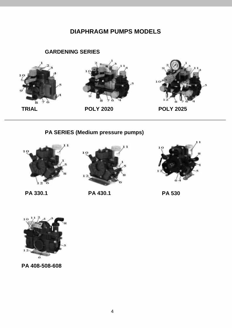
DIAPHRAGM PUMPS MODELS
GARDENING SERIES
TRIAL POLY 2020 POLY 2025
PA 330.1 PA 430.1 PA 530
PA 408-508-608
PA SERIES (Medium pressure pumps)
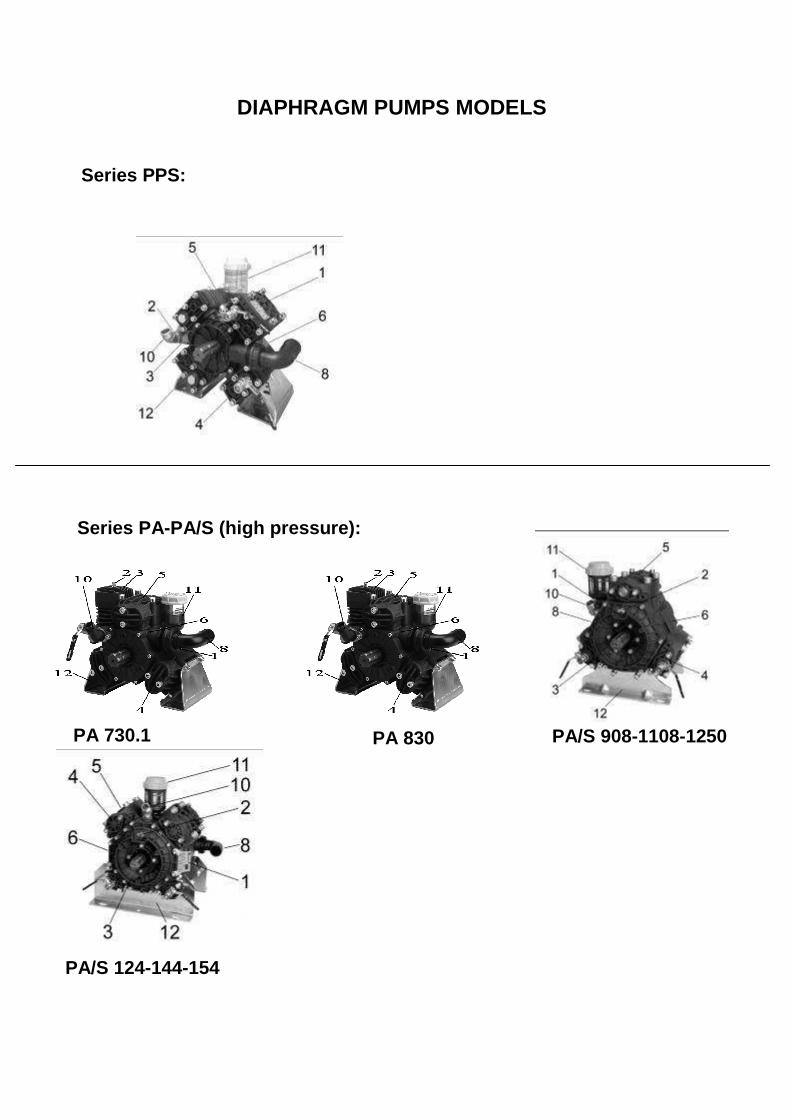
DIAPHRAGM PUMPS MODELS
Series PPS:
PA 730.1 PA 830 PA/S 908-1108-1250
PA/S 124-144-154
Series PA-PA/S (high pressure):
- 6 -
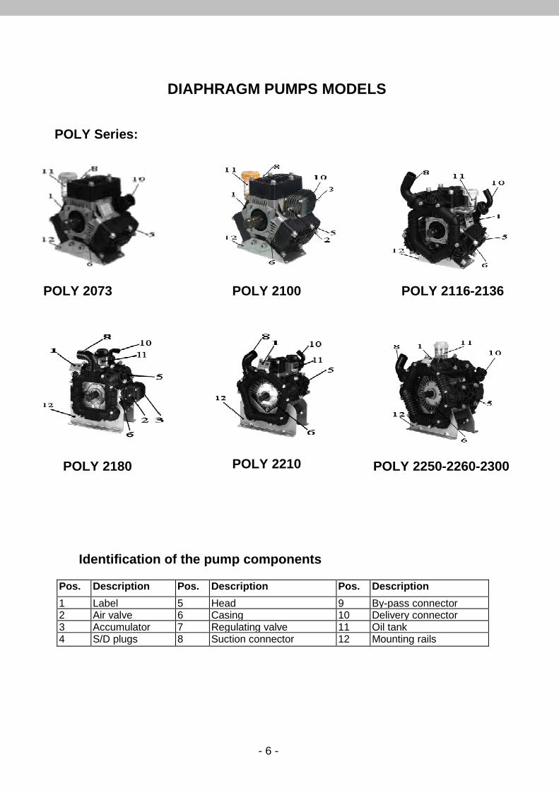
DIAPHRAGM PUMPS MODELS Identification of the pump components
Pos. Description Pos. Description Pos. Description
1 Label 5 Head 9 By-pass connector 2 Air valve 6 Casing 10 Delivery connector 3 Accumulator 7 Regulating valve 11 Oil tank 4 S/D plugs 8 Suction connector 12 Mounting rails
POLY Series:
POLY 2073 POLY 2116-2136
POLY 2180 POLY 2210 POLY 2250-2260-2300
POLY 2100
- 7 -
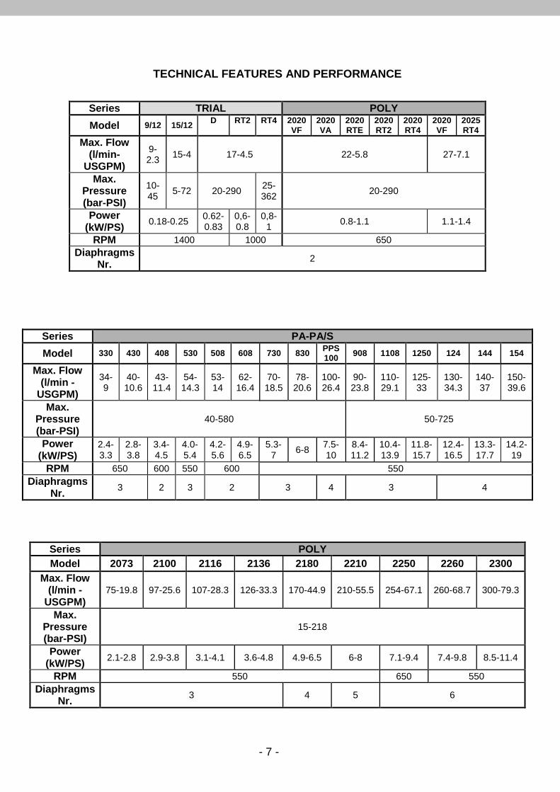
TECHNICAL FEATURES AND PERFORMANCE
Series TRIAL POLY
Model 9/12 15/12 D
RT2
RT4
2020 VF
2020 VA
2020 RTE
2020 RT2
2020 RT4
2020 VF
2025 RT4
Max. Flow (l/min-
USGPM)
9-2.3
15-4 17-4.5 22-5.8 27-7.1
Max. Pressure (bar-PSI)
10-45
5-72 20-290 25-362
20-290
Power (kW/PS)
0.18-0.25 0.62-0.83
0,6-0.8
0,8-1
0.8-1.1 1.1-1.4
RPM 1400 1000 650 Diaphragms
Nr. 2
Series PA-PA/S
Model 330 430 408 530 508 608 730 830 PPS 100 908 1108 1250 124 144 154
Max. Flow (l/min -
USGPM)
34-9
40-10.6
43-11.4
54-14.3
53-14
62-16.4
70-18.5
78-20.6
100-26.4
90-23.8
110-29.1
125-33
130-34.3
140-37
150-39.6
Max. Pressure (bar-PSI)
40-580 50-725
Power (kW/PS)
2.4-3.3
2.8-3.8
3.4-4.5
4.0-5.4
4.2-5.6
4.9-6.5
5.3-7
6-8 7.5-10
8.4-11.2
10.4-13.9
11.8-15.7
12.4-16.5
13.3-17.7
14.2-19
RPM 650 600 550 600 550 Diaphragms
Nr. 3 2 3 2 3 4 3 4
Series POLY Model 2073 2100 2116 2136 2180 2210 2250 2260 2300
Max. Flow (l/min -
USGPM) 75-19.8 97-25.6 107-28.3 126-33.3 170-44.9 210-55.5 254-67.1 260-68.7 300-79.3
Max. Pressure (bar-PSI)
15-218
Power (kW/PS)
2.1-2.8 2.9-3.8 3.1-4.1 3.6-4.8 4.9-6.5 6-8 7.1-9.4 7.4-9.8 8.5-11.4
RPM 550 650 550 Diaphragms
Nr. 3 4 5 6
- 8 -
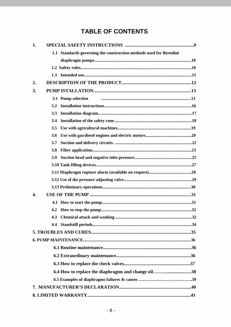
TABLE OF CONTENTS
1. SPECIAL SAFETY INSTRUCTIONS ...........................................................9
1.1 Standards governing the construction methods used for Bertolini
diaphragm pumps...........................................................................................10
1.2 Safety rules........................................................................................................10
1.3 Intended use.....................................................................................................11
2. DESCRIPTION OF THE PRODUCT............................................................12
3. PUMP ISTALLATION....................................................................................13
3.1 Pump selection ....................................................................................13
3.2 Installation instructions..................................................................................16
3.3 Installation diagram........................................................................................17
3.4 Installation of the safety cone.........................................................................18
3.5 Use with agricultural machines.....................................................................19
3.6 Use with gas/diesel engines and electric motors...........................................20
3.7 Suction and delivery circuits. ........................................................................22
3.8 Filter application.............................................................................................23
3.9 Suction head and negative inlet pressure......................................................25
3.10 Tank filling devices..........................................................................................27
3.11 Diaphragm rupture alarm (available on request)........................................28
3.12 Use of the pressure adjusting valve................................................................29
3.13 Preliminary operations...................................................................................30
4. USE OF THE PUMP .......................................................................................31
4.1 How to start the pump....................................................................................31
4.2 How to stop the pump.....................................................................................32
4.3 Chemical attack and washing ........................................................................32
4.4 Standstill periods.............................................................................................34
5. TROUBLES AND CURES......................................................................................35
6. PUMP MAINTENANCE.....................................................................................................36
6.1 Routine maintenance............................................................................36
6.2 Extraordinary maintenance................................................................36
6.3 How to replace the check valves.........................................................37
6.4 How to replace the diaphragms and change oil……….....................38
6.5 Examples of diaphragms failures & causes ………………………………..39
7. MANUFACTURER’S DECLARATION..............................................................40
8. LIMITED WARRANTY.........................................................................................41
- 9 -
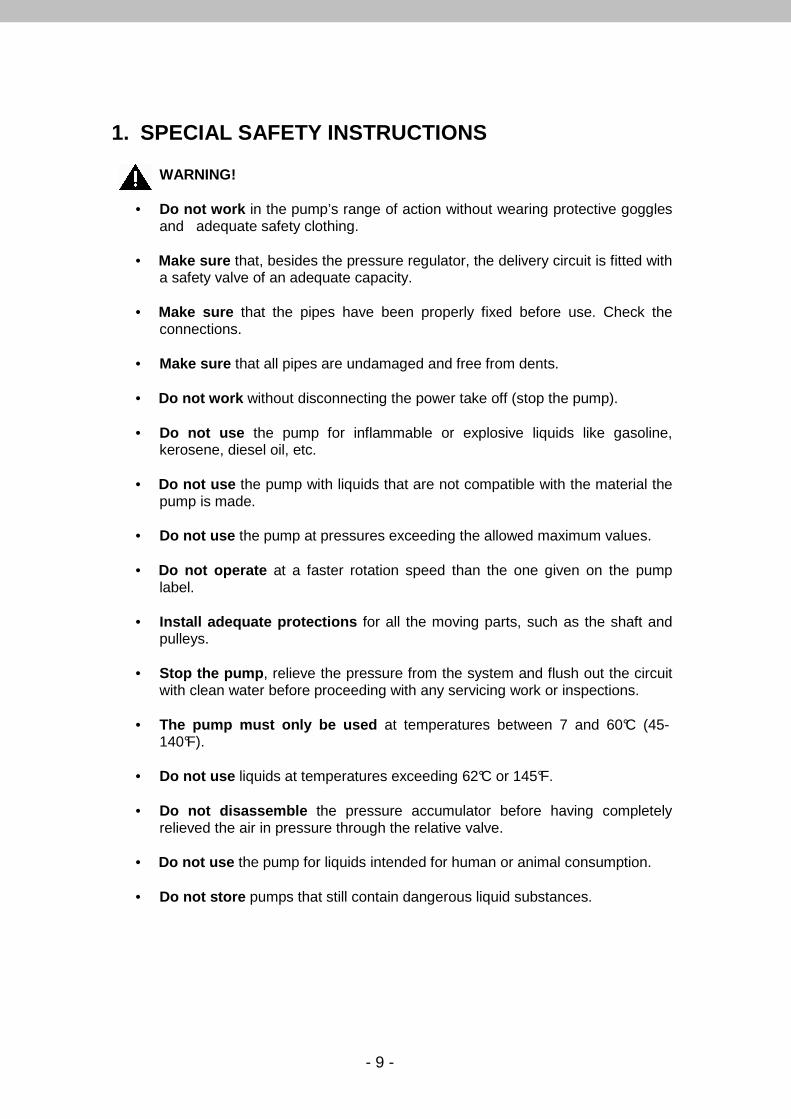
1. SPECIAL SAFETY INSTRUCTIONS
WARNING!
• Do not work in the pump’s range of action without wearing protective goggles and adequate safety clothing.
• Make sure that, besides the pressure regulator, the delivery circuit is fitted with
a safety valve of an adequate capacity.
• Make sure that the pipes have been properly fixed before use. Check the connections.
• Make sure that all pipes are undamaged and free from dents.
• Do not work without disconnecting the power take off (stop the pump).
• Do not use the pump for inflammable or explosive liquids like gasoline,
kerosene, diesel oil, etc.
• Do not use the pump with liquids that are not compatible with the material the pump is made.
• Do not use the pump at pressures exceeding the allowed maximum values.
• Do not operate at a faster rotation speed than the one given on the pump
label.
• Install adequate protections for all the moving parts, such as the shaft and pulleys.
• Stop the pump , relieve the pressure from the system and flush out the circuit
with clean water before proceeding with any servicing work or inspections.
• The pump must only be used at temperatures between 7 and 60°C (45-140°F).
• Do not use liquids at temperatures exceeding 62°C or 145°F.
• Do not disassemble the pressure accumulator before having completely
relieved the air in pressure through the relative valve.
• Do not use the pump for liquids intended for human or animal consumption.
• Do not store pumps that still contain dangerous liquid substances.

- 10 -
1.1 Standards governing the construction methods used for Bertolini diaphragm pumps
• Directive EEC 2006/42 “Machine directive” • Directive EEC 2000/14 “Noise emission” • UNI EN 809 “Liquid pumps and pumping assemblies” • UNI EN 12162 “Liquid pumps” – “Safety requirements” – “Hydrostatic test
procedures”
1.2 Safety rules With regard to safety, all pumps meet the regulations in force UNI EN 809. The manufacturer should select the pump type according to the kind of liquid used and to the technical specifications (output, pressure) to fulfil. The Bertolini diaphragm pumps are designed with materials that are compatible with water and with the most of pesticides and herbicides currently on the market in the concentration recommended by the producers. The pumps should be used only with liquids compatible with the pump component materials. Failure to follow this warning can result in injury and/or property damage. The technical specifications of the pump (RPM, output, pressure) are shown on the label put on the pump. For more information refer to our Technical Department. The manufacturer should take care of the proper selection and correct size of the operation system to prevent possibly bodily injury. Make certain that the electric, gasoline/diesel motors, or driven systems conform to the recommended performance, to prevent personal injury and environment damage. The manufacturer should take a special care of the design and construction of the equipment, to prevent bodily injury, coming not from the pump, but from the design, construction or wrong use of the equipment. When wiring an electrically driven pump follow all electrical and safety regulations EN 60204.1 (refer to “Installation”).
- 11 -
1.3 Intended use The pump is exclusively designed for:
– Use with clean water at temperatures between +7°C a nd +60°C for non-food purposes.
– Use with chemical products such as fertilizers, weed killers, fungicides, etc., in a watery solution and always compatible with the materials the pump is made. (Remember that the diaphragms are normally made of BUNA – N and, on request, in DESMOPAN, VITON or HPS®, while the O-Rings are normally in NBR).
The pump cannot be used with:
– Watery solutions whose viscosity and density exceed those of water. – Chemical solutions for which compatibility with the materials the pump is
made is not known. – Sea water or water with a high concentration of salt – Fuels and lubricants of all kinds and types – Inflammable liquids or liquefied gases – Food-grade liquids – Solvents and diluents of all kinds and types – Paints of all kinds and types – Liquids at temperatures lower than 7°C or higher th an 60°C – Liquids containing granules or solids in suspension
The pump must not be used for washing: persons, animals, electrical equipment, delicate objects, the pump itself or the system in which it is installed. The pump must not be used in places where there are particular conditions, such as corrosive or explosive atmospheres, for example. All other use is considered improper. Idromeccanica Bertolini shall not be liable for any damage deriving from improper or incorrect use.

- 12 -
2. DESCRIPTION OF THE PRODUCT Bertolini diaphragm pumps are suitable for use with clean water at a maximum temperature of 60°C. Contact the “Bertolini technical service” if particularly corrosive additives and higher temperatures are used. The pump must be used in compliance with the specifications given on the label. Removal of the label will void all forms of warranty.
As soon as you have received the pump, make sure that the label is similar to the one depicted below.
The label gives the following information: 1. Maximum pressure in P.S.I. 2. Maximum pressure in bar 3. Maximum flow rate in l/min at the maximum pressure 4. Maximum flow rate in l/min at the minimum pressure 5. Pump model 6. Serial number 7. Maximum flow rate in U.S.G.P.M. at the maximum pressure 8. Maximum flow rate in U.S.G.P.M. at the minimum pressure 9. Minimum R.P.M. 10. Maximum R.P.M.
WARNING!
Never exceed the maximum pressure and rpm rate indi cated on the label.
WARNING! If the identification label becomes damaged through use, ask your dealer or an authorized assistance center for a replacemen t.
- 13 -
3. PUMP INSTALLATION
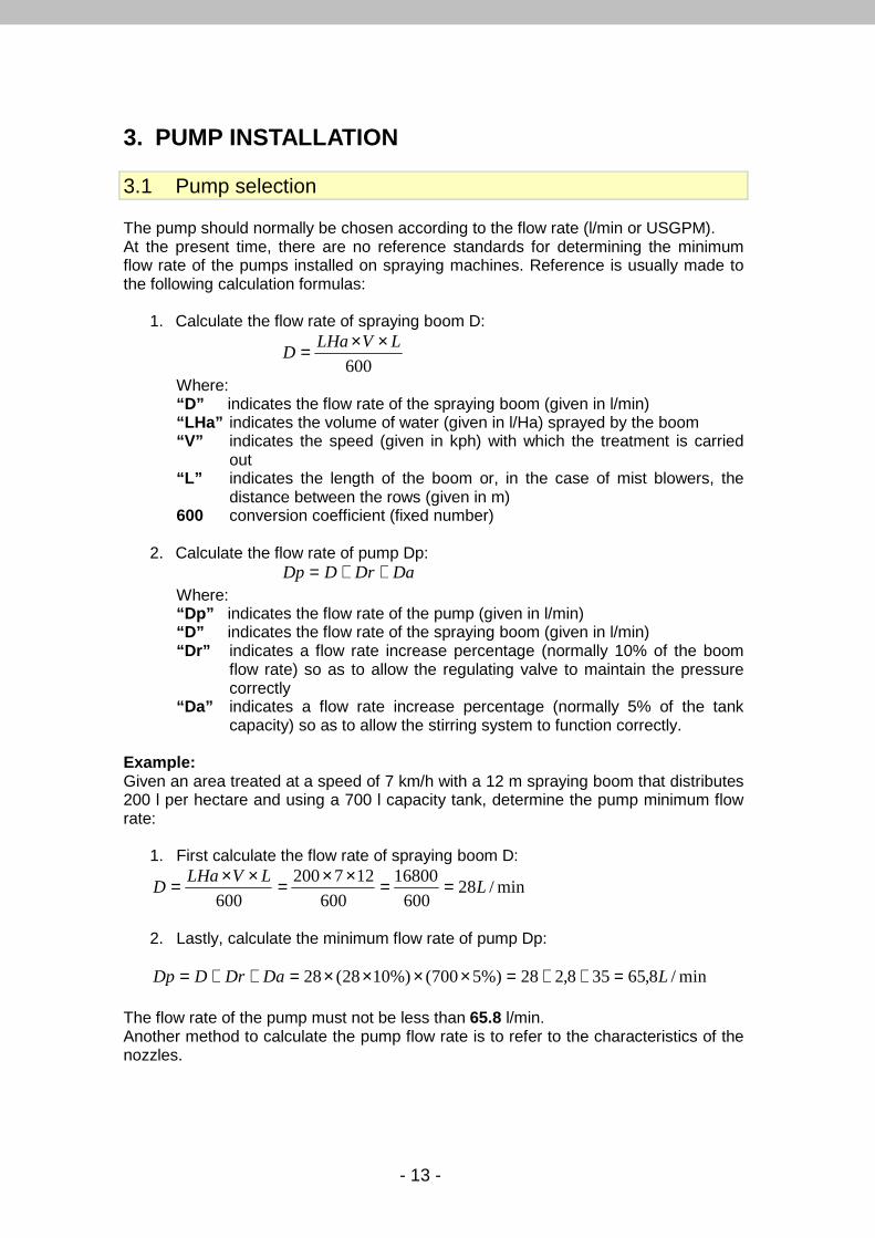
3.1 Pump selection The pump should normally be chosen according to the flow rate (l/min or USGPM). At the present time, there are no reference standards for determining the minimum flow rate of the pumps installed on spraying machines. Reference is usually made to the following calculation formulas:
1. Calculate the flow rate of spraying boom D:
600
LVLHaD
××=
Where: “D” indicates the flow rate of the spraying boom (given in l/min) “LHa” indicates the volume of water (given in l/Ha) sprayed by the boom “V” indicates the speed (given in kph) with which the treatment is carried
out “L” indicates the length of the boom or, in the case of mist blowers, the
distance between the rows (given in m) 600 conversion coefficient (fixed number)
2. Calculate the flow rate of pump Dp:
DaDrDDp ++= Where: “Dp” indicates the flow rate of the pump (given in l/min) “D” indicates the flow rate of the spraying boom (given in l/min) “Dr” indicates a flow rate increase percentage (normally 10% of the boom
flow rate) so as to allow the regulating valve to maintain the pressure correctly
“Da” indicates a flow rate increase percentage (normally 5% of the tank capacity) so as to allow the stirring system to function correctly.
Example: Given an area treated at a speed of 7 km/h with a 12 m spraying boom that distributes 200 l per hectare and using a 700 l capacity tank, determine the pump minimum flow rate:
1. First calculate the flow rate of spraying boom D:
min/28600
16800
600
127200
600L
LVLHaD ==××=××=
2. Lastly, calculate the minimum flow rate of pump Dp:
min/8,65358,228%)5700(%)1028(28 LDaDrDDp =++=××××=++=
The flow rate of the pump must not be less than 65.8 l/min. Another method to calculate the pump flow rate is to refer to the characteristics of the nozzles.
- 14 -
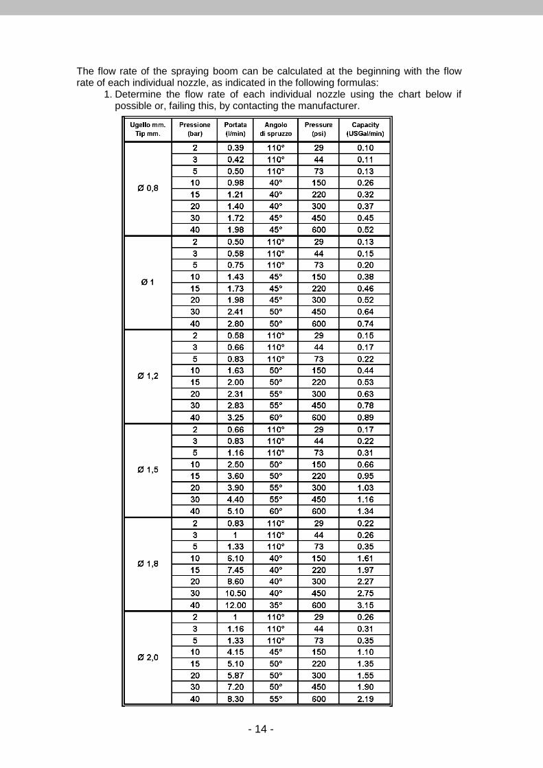
The flow rate of the spraying boom can be calculated at the beginning with the flow rate of each individual nozzle, as indicated in the following formulas:
1. Determine the flow rate of each individual nozzle using the chart below if possible or, failing this, by contacting the manufacturer.
- 15 -
2. Calculate the flow rate of spraying boom D:
NuDuD ×=
Where: “D” indicates the flow rate of the spraying boom (given in l/min) “Du” indicates the flow rate of the individual nozzles (given in l/min) “Nu” indicates the number of nozzles used
3. Calculate the flow rate of pump Dp:
DaDrDDp ++=
Where: “Dp” indicates the flow rate of the pump (given in l/min) “D” indicates the flow rate of the spraying boom (given in l/min) “Dr” indicates a flow rate increase percentage (normally 10% of the
boom’s flow rate) so as to allow the regulating valve to maintain the pressure correctly
“Da” indicates a flow rate increase percentage (normally 5% of the tank capacity) so as to allow the agitation system to function correctly.
However, it is worthwhile remembering that these are rough calculation methods and applicable to spraying machines where the liquid is stirred in the tank solely by the part of the pump flow that returns. The efficiency of the mixing system often depends largely on the technical solutions used (mixing points and methods) and on the construction features (shape, materials) of the tank rather than on the extent of the flow rate available for that operation.

- 16 -
3.2 Installation instructions.
WARNING!
• The pump can be set at work only if the machine in which it is installed conforms to the safety standards established by the European Directives. This fact is guaranteed by the CE mark applied and by the Declaration of Conformity provided by the manufacturer of the mach ine in which the pump is installed;
• Do not use the pump if it has been subjected to strong impact; • Do not use the pump if there are evident oil leaks; • Take great care when using the pump in places where there are moving
vehicles that could crush or damage the delivery hose and spray gun. • Pump should be installed perfectly lined up with the driven gears (pulleys,
gearboxes, overgears etc.). • Be sure that pump is attached to a strong base plate and anchor it with bolts
sufficiently strong to hold it in place. • Use suction, discharge and by-pass hoses of proper diameter, al least the same
diameter as the pump hose barb or greater. Use spiral steel wire braid reinforced suction hose to prevent collapse. Use good quality hose clamps and tighten securely. Use only components (hose, fittings, clamps etc.) Rated for max. Pressure rating of the pump.
• Always remember to fit the safety cone on the transmission shaft so as to prevent persons from being injured.
• Since the pump is the displacement type, it must always be equipped with a pressure regulating valve.
Failure to follow the above information can result in malfunctions of the pump and will void the product warranty.
- 17 -
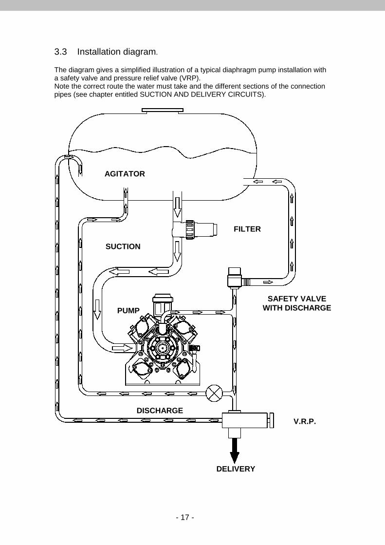
3.3 Installation diagram. The diagram gives a simplified illustration of a typical diaphragm pump installation with a safety valve and pressure relief valve (VRP). Note the correct route the water must take and the different sections of the connection pipes (see chapter entitled SUCTION AND DELIVERY CIRCUITS).
AGITATOR
SUCTION
FILTER
PUMP
DISCHARGE
SAFETY VALVE WITH DISCHARGE
V.R.P.
DELIVERY
- 18 -
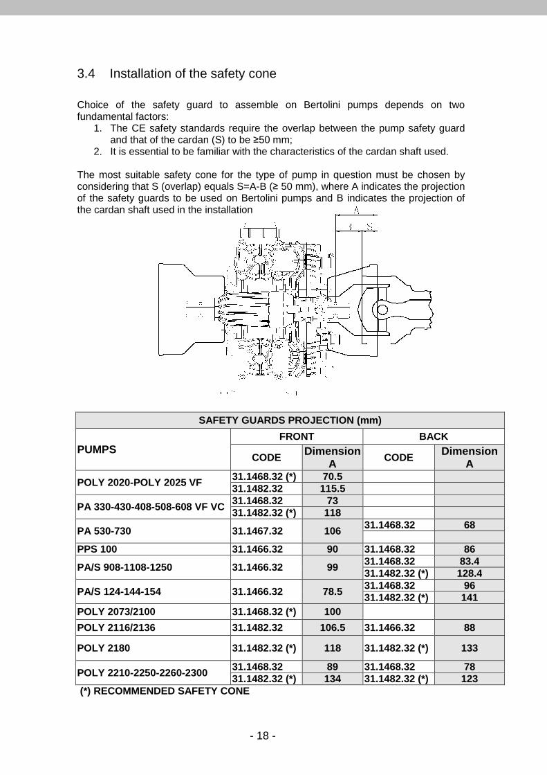
3.4 Installation of the safety cone Choice of the safety guard to assemble on Bertolini pumps depends on two fundamental factors:
1. The CE safety standards require the overlap between the pump safety guard and that of the cardan (S) to be ≥50 mm;
2. It is essential to be familiar with the characteristics of the cardan shaft used. The most suitable safety cone for the type of pump in question must be chosen by considering that S (overlap) equals S=A-B (≥ 50 mm), where A indicates the projection of the safety guards to be used on Bertolini pumps and B indicates the projection of the cardan shaft used in the installation
(*) RECOMMENDED SAFETY CONE
SAFETY GUARDS PROJECTION (mm)
PUMPS FRONT BACK
CODE Dimension A
CODE Dimension A
POLY 2020-POLY 2025 VF 31.1468.32 (*) 70.5 31.1482.32 115.5
PA 330-430-408-508-608 VF VC 31.1468.32 73 31.1482.32 (*) 118
PA 530-730 31.1467.32 106 31.1468.32 68
PPS 100 31.1466.32 90 31.1468.32 86
PA/S 908-1108-1250 31.1466.32 99 31.1468.32 83.4 31.1482.32 (*) 128.4
PA/S 124-144-154 31.1466.32 78.5 31.1468.32 96 31.1482.32 (*) 141
POLY 2073/2100 31.1468.32 (*) 100
POLY 2116/2136 31.1482.32 106.5 31.1466.32 88
POLY 2180 31.1482.32 (*) 118 31.1482.32 (*) 133
POLY 2210-2250-2260-2300 31.1468.32 89 31.1468.32 78 31.1482.32 (*) 134 31.1482.32 (*) 123

- 19 -
3.5 Use with agricultural machines
WARNING! All rotating parts must be protected. The tractor a nd pump guards form an integrated system with the cardan shaft guard. Care fully read the manual supplied with the cardan shaft. There are two possibilities of choosing the right type of cardan shaft and the way in which it is used: 1. If the cardan shaft is merely used to operate the pump, greater differences
between the two joint angles (α1 and α2) can be accepted, thus a somewhat irregular motion, as illustrated in the specialized catalogues.
2. If the pump transmits the motion received from the cardan shaft to other devices (e.g. a fan driven by an overdrive) by means of a through shaft, the inertial masses involved in the motion can be considerable. In this case, the transmission only accepts very small speed oscillations so as to prevent parts from breaking. The following rules must be strictly respected in this sort of situation:
• A shaft with two single joints can only be used when the difference between angles α1 and α2 is no more than 12°.
• If the difference between the two angles α1 e α2 is >12°, use a cardan shaft with a constant speed universal joint and a single joint.
In this sort of situation, it is necessary to remember that the difference between angles α1 e α2 of the single joint must never exceed 12°. If thi s occurs, another constant speed universal joint must be added.
During the curve in operating conditions, cardan shafts lead to the creation of axial thrusts on the shafts to which they are connected. These forces may actually break parts of the pump. To keep them within acceptable limits, the entire cardan shaft, i.e. both the joints and the telescopic shafts, must be kept constantly lubricated, as described by the manufacturer. In the maximum curve condition, also make sure that the cardan shaft never becomes completely closed, since this would certainly break parts of the mechanism.
Tractor
Mist blower
Tractor
Mist blower
Cons speed universal joint

- 20 -
3.6 Use with gas/diesel engines and electric motors
WARNING! All the electrical connections must be made by spec ialized technicians. Do not work on the pump or electric pump with wet h ands, in a wet environment or on a wet surface. Contact the Bertolini customer assistance service o r the dealer from whom the pump was purchased for any help required with the i nstallation or use. This will prevent annoying faults in relation to which the ma nufacturer hereby declines all liability for non-compliance. – If electric motors are used, comply with the provisions established by the pertinent
standard EN60204-1 in order to avoid risks of an electrical nature. – The pulleys and belts must be adequately protected and covered in a suitable way,
in accordance with the norms in force. – It is essential to periodically check to make sure that the pulleys are correctly
aligned and the belts tightened to the extent indicated by the manufacturer. – Besides leading to early wear on the belts, failure to comply with the regulations
may cause the pump to overheat and damage to the bearings.
Motor R.p.m. Maximum transmission ratio = K Pump R.p.m. After determining K, you can calculate the motor or pump pulley diameter: Pump pulley pitch diam Motor pulley pitch diam.: m.p. Ø =
K Pump pulley pitch diameter = p.p. Ø = motor pulley pitch Ø x K Calculation example: The calculation must establish the pitch diameter of a pulley to apply to a 3000 r.p.m. engine that must operate a PA530 Bertolini pump (550 rpm) in which a Ø 350 mm pulley must be installed, as indicated in the Bertolini catalogue and in the chart on the next page: First calculate the transmission ratio K: engine r.p.m. 3000 K= = = 5.45 pump r.p.m. 550 Having determined K and after having chosen the pump pulley Ø, the engine pulley Ø can be calculated in the following way: Pump pulley Ø 350 E.P.Ø= = = 64 mm
K 5.45
- 21 -
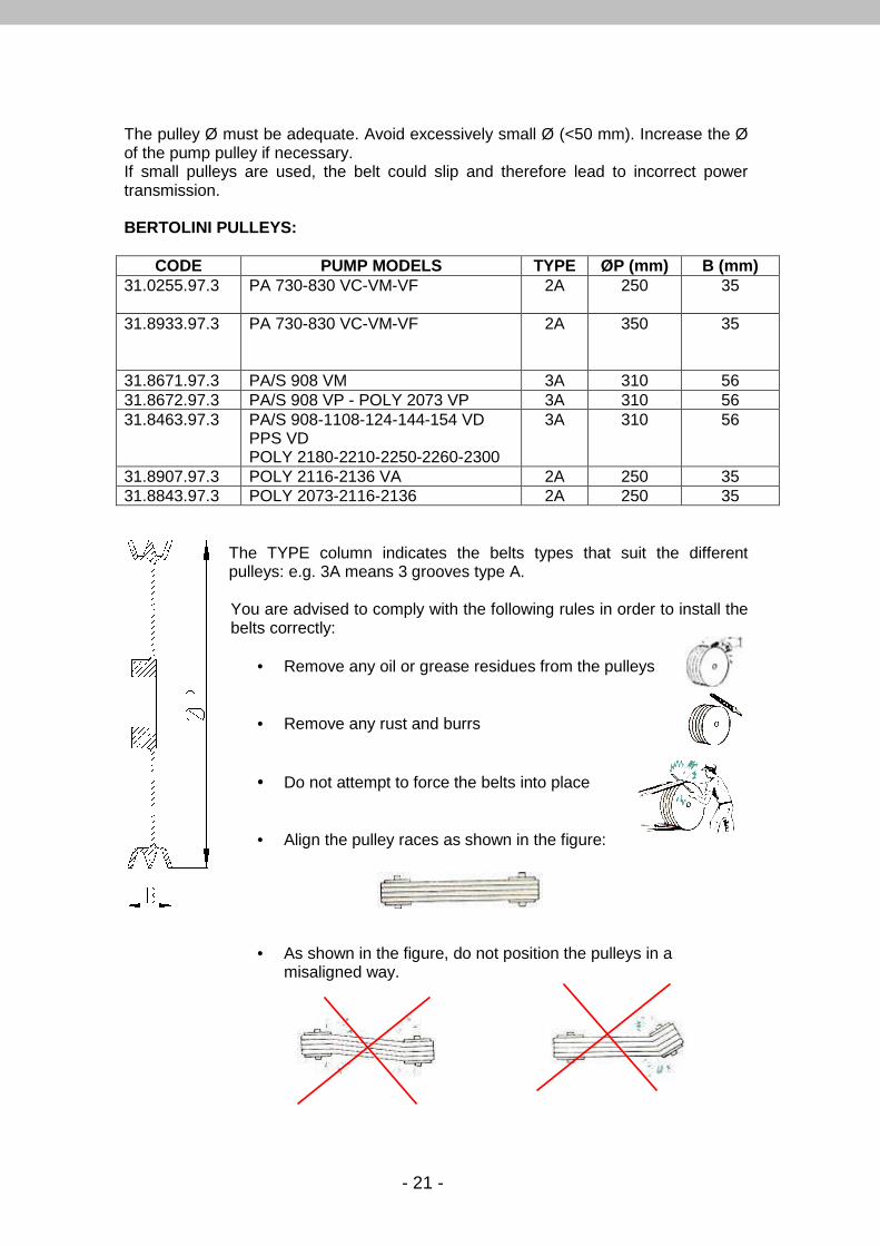
The pulley Ø must be adequate. Avoid excessively small Ø (<50 mm). Increase the Ø of the pump pulley if necessary. If small pulleys are used, the belt could slip and therefore lead to incorrect power transmission. BERTOLINI PULLEYS:
CODE PUMP MODELS TYPE ØP (mm) B (mm) 31.0255.97.3 PA 730-830 VC-VM-VF 2A
250 35
31.8933.97.3 PA 730-830 VC-VM-VF 2A
350 35
31.8671.97.3 PA/S 908 VM 3A 310 56 31.8672.97.3 PA/S 908 VP - POLY 2073 VP 3A 310 56 31.8463.97.3 PA/S 908-1108-124-144-154 VD
PPS VD POLY 2180-2210-2250-2260-2300
3A 310 56
31.8907.97.3 POLY 2116-2136 VA 2A 250 35 31.8843.97.3 POLY 2073-2116-2136 2A 250 35 The TYPE column indicates the belts types that suit the different
pulleys: e.g. 3A means 3 grooves type A.
You are advised to comply with the following rules in order to install the belts correctly:
• Remove any oil or grease residues from the pulleys
• Remove any rust and burrs
• Do not attempt to force the belts into place
• Align the pulley races as shown in the figure:
• As shown in the figure, do not position the pulleys in a misaligned way.
- 22 -
3.7 Suction and delivery circuits The suction hose must be installed in such a way as to prevent air pockets from forming. Make sure that the hose is routed over the shortest possible distance. The diameter of the hose must be the same as that of the pipe fitting, hose must be fitted on down to the elbow and fastened with good quality clamps. Always allow for a safety margin in relation to the hose length, so as to prevent the clamps from slipping off or loosening owing to vibrations from the system. It is advisable to periodically check these connections, which could allow air to enter. Air drawn in by the pump could cause faults and early failures of the diaphragms. The hose must be able to bend without throttling the circuit. The ideal hose is the type with a steel coil, which is flexible while being light and able to maintain its shape. All the threaded connections must be assembled with PTFE, specific adhesive or equivalent, so as to ensure a perfect seal. If the route is direct, the dimensions of the pipes and pipe fittings must not be less than the diameter of the pipe fittings supplied with the pump. If elbows and/or three-way valves or similar must be installed, the circuit size must be increased in relation to their number. The clear passage (meaning the minimum diameter of the ball hole and not of the thread) of any three-way valves or equivalent, must not be less than the internal diameter of the pump suction pipe fitting . The manufacturer must take particular care when designing the delivery system so as to avoid danger hazards to persons caused, not by the pump, but by the way the system in which the pump is installed has been designed, constructed or improperly used.
To avoid excessive pressure in the manifold, make sure that the delivery hoses are adequately sized. In any case, they must be no smaller than the diameter of the pipe fitting supplied with the pump.
Only use components (hoses, pipe fittings, clamps, etc.) whose minimum characteristics are equal to the maximum pressure of the pump.

- 23 -
3.8 Filter application
Use of suction filters with closing valves of an in adequate capacity will immediately void the warranty.
Never use on line filters (between the pump and the regulating valve) instead of suction filters (prior to the pump). The on line filters must only be installed after the regulating valve, on the delivery line before the nozzles. Suction filters with automatic closing valve must be sized with an adequate capacity after inspection of the clear passage area, which must not be less than that of the pipe fitting supplied with the pump. For example:
• Poly 2180 pump - flow rate 170 l/min. • Ø 45 standard suction pipe fitting at 90° • Suction filter without valve , with 32 mesh cartridge
If a three-way valve and/or a suction filter with automatic closing valve is added to the circuit, this latter must be modified in the following way:
• Ø 50 suction pipe fitting at 90° • Suction filter with automatic closing valve , with 32 mesh cartridge.
The filtering capacity of the suction filter must be at least two and a half times the pump flow rate, and the recommended diameter of the holes must be:
• 32 mesh for charging cartridge from the pump suction
Suction filter without valve
Suction filter with closing valve (NOT RECOMMENDED ON THE INTAKE)

- 24 -
The term MESH means the number of openings per linear inch of wire gauze. For example, a 32 MESH filter will have 32 holes per linear inch of the filter gauze. If the MESH value is squared (e.g. 32² = 1024), the result is the number of holes per square inch. Thus, the greater the mesh value is, the greater the filtering capacity of the filter will be. Always install 32 mesh cartridges and oversized filters if chemicals in powder form or very thick fluids are used , so as to allow for a greater safety margin against clogging during the treatments.
Remember that the best results are not always achieved by using a filter with a high MESH value.
For example, if water is drawn from a ditch with 80 MESH filter, the pump suction side could become very quickly clogged and throttled, thus preventing it from functioning correctly.
It is therefore advisable to use pump suction filters with a filtering capacity that is not particularly high, but correctly proportioned to the pumped fluid.
If a duct that completely empties the tank is used, make sure that the filter is serviced frequently, since the impurities that settle on the bottom could lead to clogging.
It is also advisable to affix stickers and notices in clearly visible places, so as to warn the user that the filter must be frequently serviced.
The filter cartridge must be cleaned whenever the tank is refilled. This ensures that the filtering surface is always in the best condition. Scaling or particularly thick products could settle and reduce the area where the liquid is able to flow through, thus throttling the passage.
- 25 -
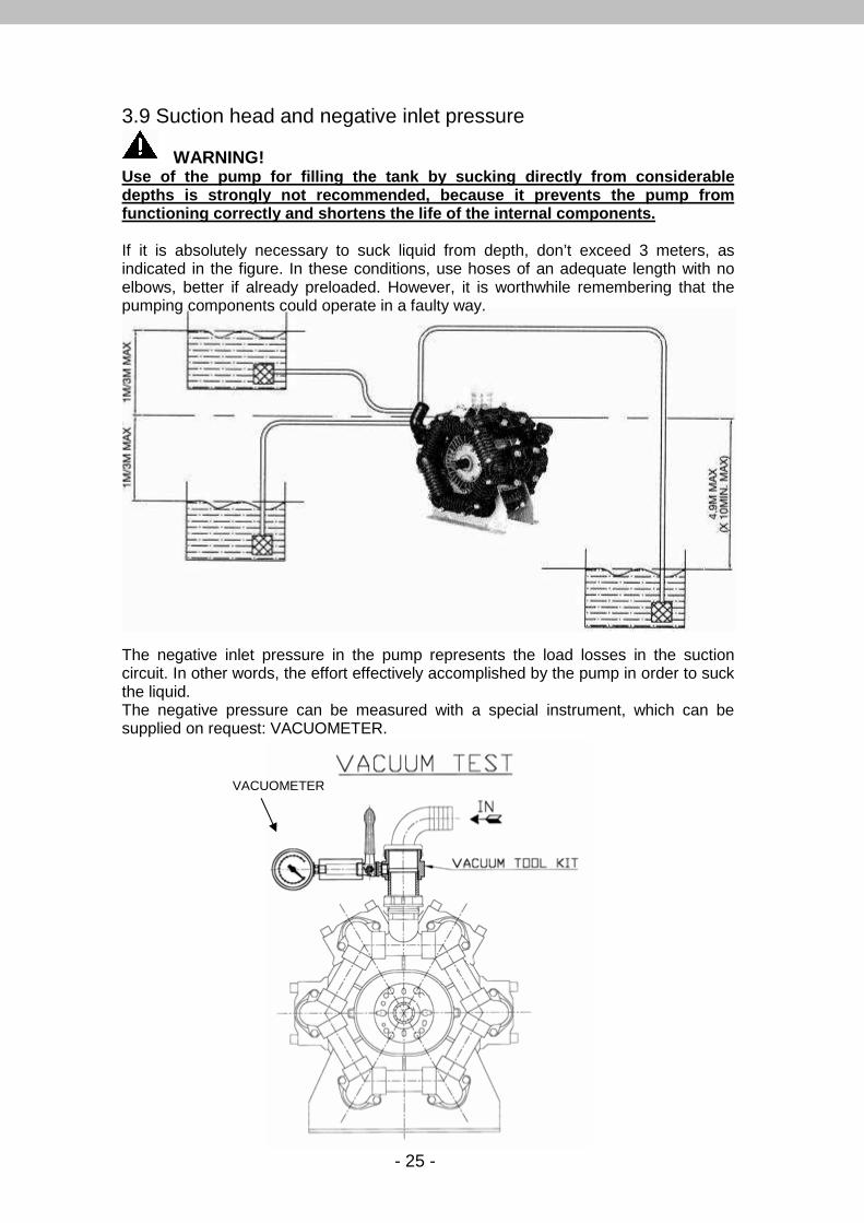
3.9 Suction head and negative inlet pressure
WARNING! Use of the pump for filling the tank by sucking dir ectly from considerable depths is strongly not recommended, because it prev ents the pump from functioning correctly and shortens the life of the internal components. If it is absolutely necessary to suck liquid from depth, don’t exceed 3 meters, as indicated in the figure. In these conditions, use hoses of an adequate length with no elbows, better if already preloaded. However, it is worthwhile remembering that the pumping components could operate in a faulty way. The negative inlet pressure in the pump represents the load losses in the suction circuit. In other words, the effort effectively accomplished by the pump in order to suck the liquid. The negative pressure can be measured with a special instrument, which can be supplied on request: VACUOMETER.
VACUOMETER

- 26 -
As shown in the figure, the Vacuum test kit consists of a pipe fitting, a tap and a vacuometer assembled in series on the pump suction side. Once the kit has been installed, and when the pump is operating correctly at the full rate allowed for the model in question, the vacuometer will indicate the negative pressure (vacuum) to which the pump is subjected. The maximum allowed negative inlet pressure is normally -0.25 bar (-187 mm/hg, -3.6 PSI), which increases by a maximum 10% when the maximum operating pressure of the pump is reached. This value is the sum of the different factors in the suction circuit, which can be: - Presence of narrow bends, - Presence of accessories, like filters, three-way valves, etc., - Excessive difference in level (negatively) between the pump and the tank whence
the liquid is sucked, - Excessively long pipes, - Clogged suction hoses. If the negative pressure exceeds the values given above, the pump diaphragms will no longer be subjected to a standard distortion as in fig. 1, but to an abnormal distortion as shown in fig. 2, thus compromising the operation and, consequently, the life of the pump. (fig.1) (fig.2) A pad of oil normally forms between the piston and diaphragm, and supports the overlying pressure. This means that the diaphragm will never touch the piston, but will be protected and lubricated. Excessive vacuum tends to increase this pad of oil, causing the diaphragm to stretch. It can even be pushed to touch the locking plate in an abnormal way, or even the head. In this case, the oil in the tank may decrease and even disappear, without any sign of leak. Idromeccanica Bertolini declines all liability for improper use of the pump. Moreover, such action voids the warranty.
CORRECT DISTORTION INCORRECT DISTORTION
- 27 -
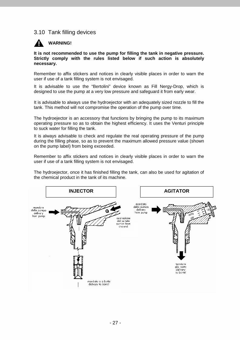
3.10 Tank filling devices
WARNING! It is not recommended to use the pump for filling t he tank in negative pressure. Strictly comply with the rules listed below if such action is absolutely necessary. Remember to affix stickers and notices in clearly visible places in order to warn the user if use of a tank filling system is not envisaged.
It is advisable to use the “Bertolini” device known as Fill Nergy-Drop, which is designed to use the pump at a very low pressure and safeguard it from early wear.
It is advisable to always use the hydroejector with an adequately sized nozzle to fill the tank. This method will not compromise the operation of the pump over time.
The hydroejector is an accessory that functions by bringing the pump to its maximum operating pressure so as to obtain the highest efficiency. It uses the Venturi principle to suck water for filling the tank.
It is always advisable to check and regulate the real operating pressure of the pump during the filling phase, so as to prevent the maximum allowed pressure value (shown on the pump label) from being exceeded. Remember to affix stickers and notices in clearly visible places in order to warn the user if use of a tank filling system is not envisaged.
The hydroejector, once it has finished filling the tank, can also be used for agitation of the chemical product in the tank of its machine.
INJECTOR AGITATOR
- 28 -
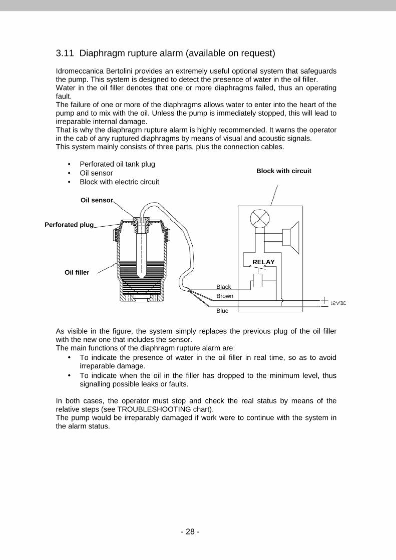
3.11 Diaphragm rupture alarm (available on request) Idromeccanica Bertolini provides an extremely useful optional system that safeguards the pump. This system is designed to detect the presence of water in the oil filler. Water in the oil filler denotes that one or more diaphragms failed, thus an operating fault. The failure of one or more of the diaphragms allows water to enter into the heart of the pump and to mix with the oil. Unless the pump is immediately stopped, this will lead to irreparable internal damage. That is why the diaphragm rupture alarm is highly recommended. It warns the operator in the cab of any ruptured diaphragms by means of visual and acoustic signals. This system mainly consists of three parts, plus the connection cables.
• Perforated oil tank plug • Oil sensor • Block with electric circuit
As visible in the figure, the system simply replaces the previous plug of the oil filler with the new one that includes the sensor. The main functions of the diaphragm rupture alarm are:
• To indicate the presence of water in the oil filler in real time, so as to avoid irreparable damage.
• To indicate when the oil in the filler has dropped to the minimum level, thus signalling possible leaks or faults.
In both cases, the operator must stop and check the real status by means of the relative steps (see TROUBLESHOOTING chart). The pump would be irreparably damaged if work were to continue with the system in the alarm status.
Oil sensor
Perforated plug
Oil filler
Block with circuit
RELAY
Blue
Black
Brown
- 29 -
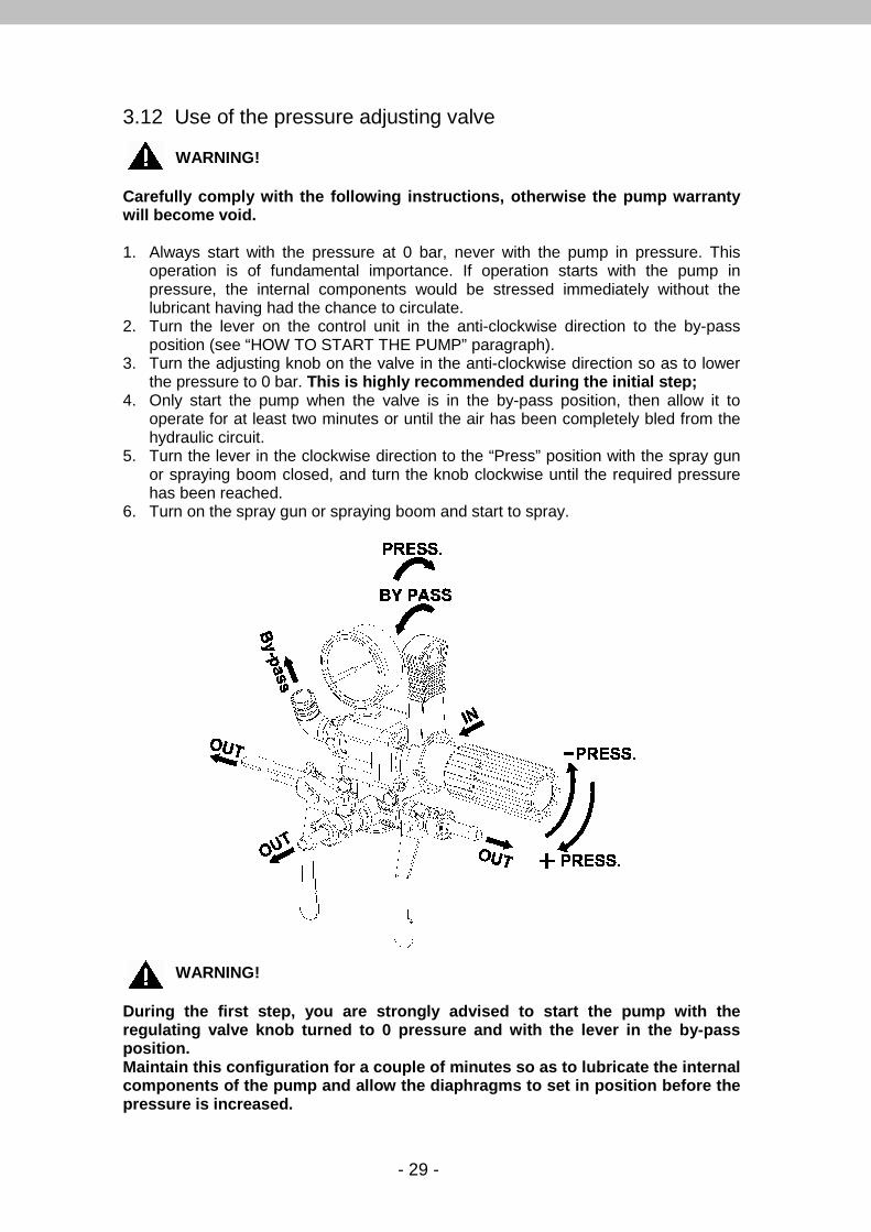
3.12 Use of the pressure adjusting valve
WARNING! Carefully comply with the following instructions, o therwise the pump warranty will become void. 1. Always start with the pressure at 0 bar, never with the pump in pressure. This
operation is of fundamental importance. If operation starts with the pump in pressure, the internal components would be stressed immediately without the lubricant having had the chance to circulate.
2. Turn the lever on the control unit in the anti-clockwise direction to the by-pass position (see “HOW TO START THE PUMP” paragraph).
3. Turn the adjusting knob on the valve in the anti-clockwise direction so as to lower the pressure to 0 bar. This is highly recommended during the initial step;
4. Only start the pump when the valve is in the by-pass position, then allow it to operate for at least two minutes or until the air has been completely bled from the hydraulic circuit.
5. Turn the lever in the clockwise direction to the “Press” position with the spray gun or spraying boom closed, and turn the knob clockwise until the required pressure has been reached.
6. Turn on the spray gun or spraying boom and start to spray.
WARNING! During the first step, you are strongly advised to start the pump with the regulating valve knob turned to 0 pressure and with the lever in the by-pass position. Maintain this configuration for a couple of minutes so as to lubricate the internal components of the pump and allow the diaphragms to set in position before the pressure is increased.
- 30 -
3.13 Preliminary operations
WARNING!
• Make sure that when the pump is operating, the oil level reaches the reference mark, depending on the type of pump. Only use oil or semi-hydraulic oil SAE 30.
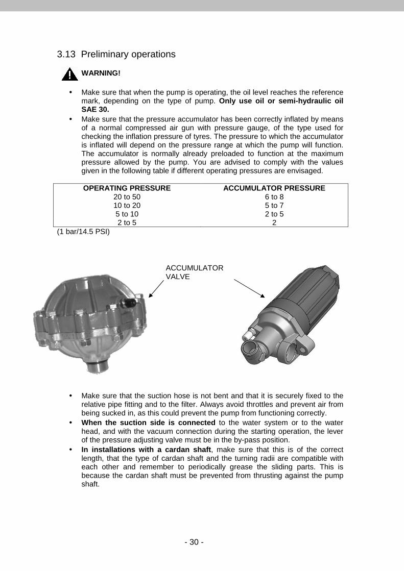
• Make sure that the pressure accumulator has been correctly inflated by means of a normal compressed air gun with pressure gauge, of the type used for checking the inflation pressure of tyres. The pressure to which the accumulator is inflated will depend on the pressure range at which the pump will function. The accumulator is normally already preloaded to function at the maximum pressure allowed by the pump. You are advised to comply with the values given in the following table if different operating pressures are envisaged.
OPERATING PRESSURE ACCUMULATOR PRESSURE
20 to 50 6 to 8 10 to 20 5 to 7 5 to 10 2 to 5 2 to 5 2
(1 bar/14.5 PSI)
• Make sure that the suction hose is not bent and that it is securely fixed to the relative pipe fitting and to the filter. Always avoid throttles and prevent air from being sucked in, as this could prevent the pump from functioning correctly.
• When the suction side is connected to the water system or to the water head, and with the vacuum connection during the starting operation, the lever of the pressure adjusting valve must be in the by-pass position.
• In installations with a cardan shaft , make sure that this is of the correct length, that the type of cardan shaft and the turning radii are compatible with each other and remember to periodically grease the sliding parts. This is because the cardan shaft must be prevented from thrusting against the pump shaft.
ACCUMULATOR VALVE
- 31 -
4. USE OF THE PUMP
4.1 How to start the pump Refer to the documentation supplied with the control unit when carrying out the following operations. Start the pump in compliance with the following instructions:
1. Reset the delivery pressure by means of the control unit, so as to bring it to the by-pass position.
2. Allow the pump to run for a few minutes at low speed so that the pressure does not exceed ¾ of its maximum value. This is very important, as it allows all the components in the pump to be correctly lubricated.
3. Increase the speed of the pump so that it is able to prime. Rotation speeds that exceed the maximum limit shown on the label will not improve the characteristics of the pump, but will cause unnecessary damage. Do not drop below the minimum revolution speed indicated on the label. The manufacturer shall not be liable for damage caused by rotation s peeds exceeding those indicated on the label.
4. Set the control unit to the “Press” position. 5. Turn the knob of the control unit until the required pressure value has been
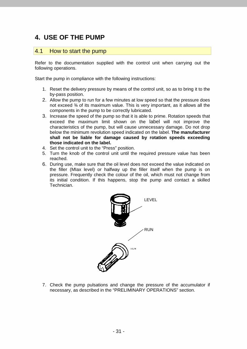
reached. 6. During use, make sure that the oil level does not exceed the value indicated on
the filler (MIax level) or halfway up the filler itself when the pump is on pressure. Frequently check the colour of the oil, which must not change from its initial condition. If this happens, stop the pump and contact a skilled Technician.
7. Check the pump pulsations and change the pressure of the accumulator if necessary, as described in the “PRELIMINARY OPERATIONS” section.
LEVEL
RUN
- 32 -
4.2 How to stop the pump
1. Reset the delivery pressure as described in point 1 of the paragraph “HOW TO START THE PUMP”
2. Stop the pump by reducing the revolutions to zero. To prevent the pump from being damaged, it is essential to flush it out after use, by allowing it to operate with clean water for a few minutes and then to empty it.
WARNING! When you stop the pump, make sure that no pipe cont ains liquid under pressure.
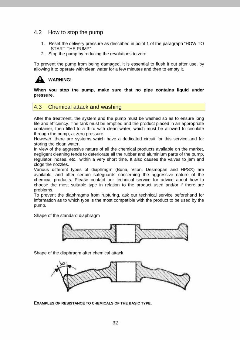
4.3 Chemical attack and washing After the treatment, the system and the pump must be washed so as to ensure long life and efficiency. The tank must be emptied and the product placed in an appropriate container, then filled to a third with clean water, which must be allowed to circulate through the pump, at zero pressure. However, there are systems which have a dedicated circuit for this service and for storing the clean water. In view of the aggressive nature of all the chemical products available on the market, negligent cleaning tends to deteriorate all the rubber and aluminium parts of the pump, regulator, hoses, etc., within a very short time. It also causes the valves to jam and clogs the nozzles. Various different types of diaphragm (Buna, Viton, Desmopan and HPS®) are available, and offer certain safeguards concerning the aggressive nature of the chemical products. Please contact our technical service for advice about how to choose the most suitable type in relation to the product used and/or if there are problems. To prevent the diaphragms from rupturing, ask our technical service beforehand for information as to which type is the most compatible with the product to be used by the pump. Shape of the standard diaphragm
Shape of the diaphragm after chemical attack EXAMPLES OF RESISTANCE TO CHEMICALS OF THE BASIC TYPE .
- 33 -
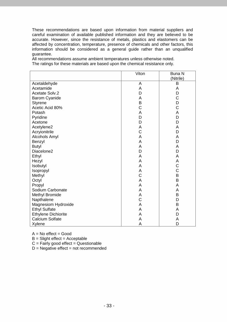
These recommendations are based upon information from material suppliers and careful examination of available published information and they are believed to be accurate. However, since the resistance of metals, plastics and elastomers can be affected by concentration, temperature, presence of chemicals and other factors, this information should be considered as a general guide rather than an unqualified guarantee. All recommendations assume ambient temperatures unless otherwise noted. The ratings for these materials are based upon the chemical resistance only. Viton Buna N
(Nitrile) Acetaldehyde Acetamide Acetate Solv.2 Barom Cyanide Styrene Acetic Acid 80% Potash Pyridine Acetone Acetylene2 Acryionitrile Alcohols Amyl Benzyl Butyl Diacelone2 Ethyl Hezyl Isobutyl Isopropyl Methyl Octyl Propyl Sodium Carbonate Methyl Bromide Napthalene Magnesiom Hydroxide Ethyl Sulfate Ethylene Dichiorite Calcium Solfate Xylene
A A D A B C A D D A C A A A D A A A A C A A A A C A A A A A
B A D C D C A D D A D A D A D A A C C B B A A B D B A D A D
A = No effect = Good B = Slight effect = Acceptable C = Fairly good effect = Questionable D = Negative effect = not recommended
- 34 -
4.4 Standstill periods
WARNING! Protect the pump from frost. If the pump is to remain idle for a long period of time, it must be completely emptied as described below:
1. Set the regulating valve in the by-pass position. 2. Allow clean water to circulate around the pump for a few minutes. Mix an
antifreeze liquid with the clean water if there is a risk of freezing. 3. Allow the pump to suck up air until all the liquid it contains has been emptied
out. Periodically (at the end of each operating season) inspect the pump and the components of the system (hoses, pipe fittings, connections, etc.). Replace all components that show signs of wear.
- 35 -
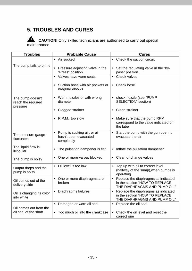
5. TROUBLES AND CURES CAUTION! Only skilled technicians are authorised to carry out special maintenance
Troubles Probable Cause Cures
The pump fails to prime
• Air sucked • Pressure adjusting valve in the
“Press” position
• Check the suction circuit • Set the regulating valve in the “by-
pass” position.
The pump doesn’t reach the required pressure
• Valves have worn seats • Suction hose with air pockets or
irregular elbows • Worn nozzles or with wrong
diameter • Clogged strainer • R.P.M. too slow
• Check valves • Check hose • check nozzle (see “PUMP
SELECTION” section) • Clean strainer • Make sure that the pump RPM
correspond to the value indicated on the label
The pressure gauge fluctuates The liquid flow is irregular The pump is noisy
• Pump is sucking air, or air hasn’t been evacuated completely
• The pulsation dampener is flat • One or more valves blocked
• Start the pump with the gun open to evacuate the air
• Inflate the pulsation dampener • Clean or change valves
Output drops and the pump is noisy
• Oil level is too low • Top up with oil to correct level (halfway of the sump),when pumps is operating
Oil comes out of the delivery side
• One or more diaphragms are broken
• Replace the diaphragms as indicated in the section “HOW TO REPLACE THE DIAPHRAGMS AND PUMP OIL”
Oil is changing its color into white
• Diaphragms failures
• Replace the diaphragms as indicated in the section “HOW TO REPLACE THE DIAPHRAGMS AND PUMP OIL”
Oil comes out from the oil seal of the shaft
• Damaged or worn oil seal • Too much oil into the crankcase
• Replace the oil seal • Check the oil level and reset the
correct one
- 36 -
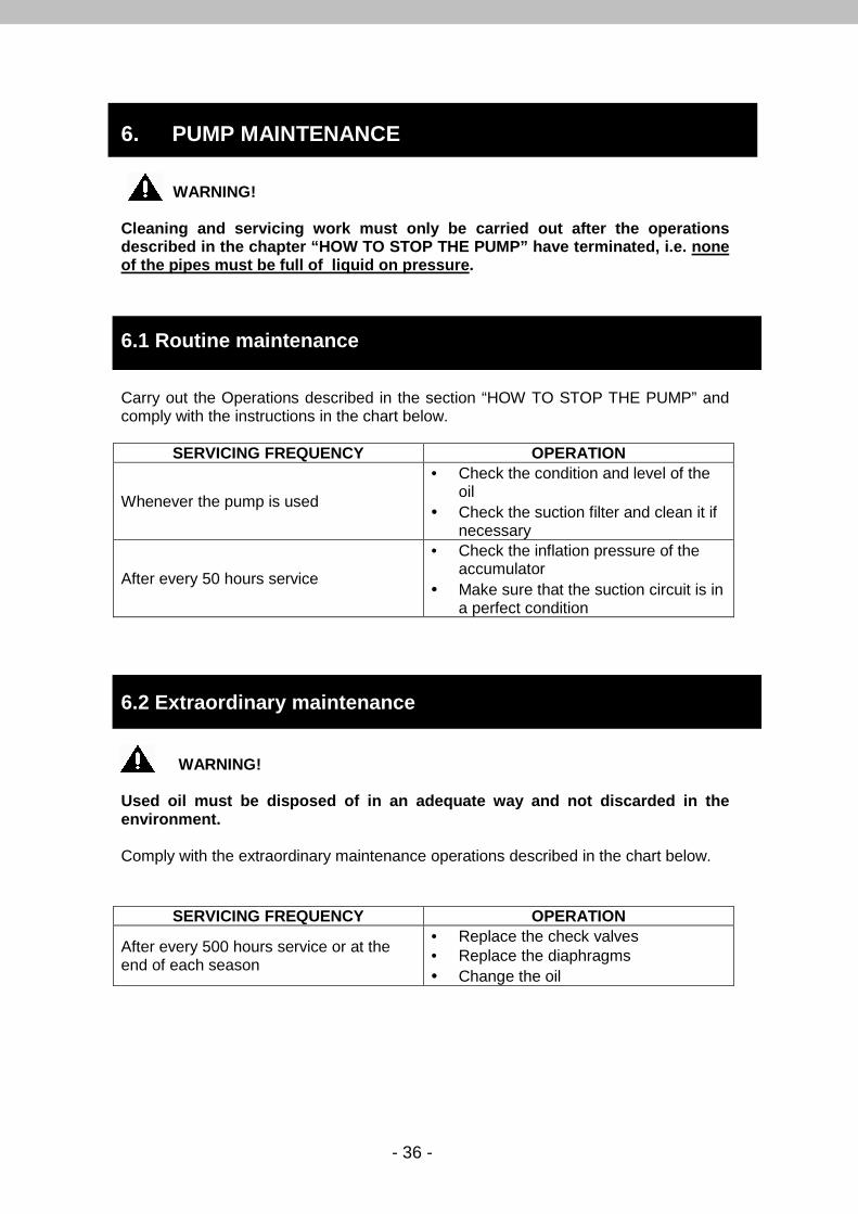
6. PUMP MAINTENANCE WARNING!
Cleaning and servicing work must only be carried ou t after the operations described in the chapter “HOW TO STOP THE PUMP” hav e terminated, i.e. none of the pipes must be full of liquid on pressure . 6.1 Routine maintenance Carry out the Operations described in the section “HOW TO STOP THE PUMP” and comply with the instructions in the chart below.
SERVICING FREQUENCY OPERATION
Whenever the pump is used
• Check the condition and level of the oil
• Check the suction filter and clean it if necessary
After every 50 hours service
• Check the inflation pressure of the accumulator
• Make sure that the suction circuit is in a perfect condition
6.2 Extraordinary maintenance WARNING! Used oil must be disposed of in an adequate way and not discarded in the environment. Comply with the extraordinary maintenance operations described in the chart below.
SERVICING FREQUENCY OPERATION
After every 500 hours service or at the end of each season
• Replace the check valves • Replace the diaphragms • Change the oil
- 37 -
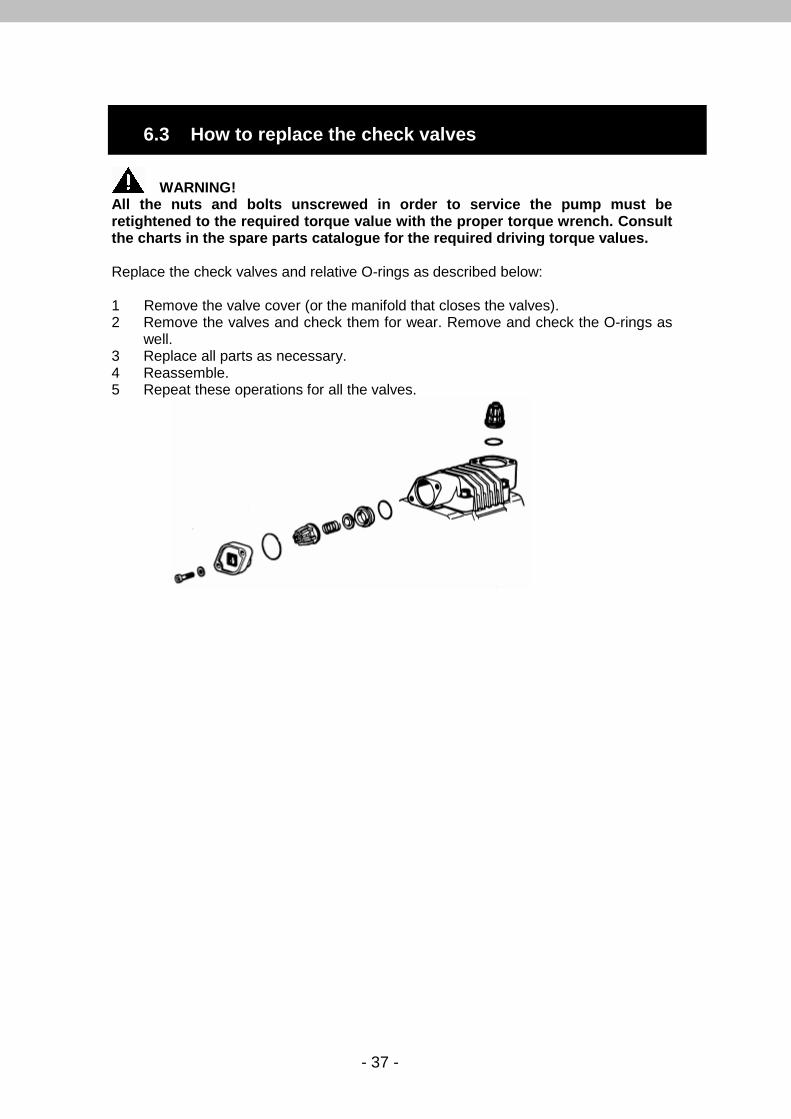
WARNING!
All the nuts and bolts unscrewed in order to servic e the pump must be retightened to the required torque value with the p roper torque wrench. Consult the charts in the spare parts catalogue for the req uired driving torque values. Replace the check valves and relative O-rings as described below: 1 Remove the valve cover (or the manifold that closes the valves). 2 Remove the valves and check them for wear. Remove and check the O-rings as
well. 3 Replace all parts as necessary. 4 Reassemble. 5 Repeat these operations for all the valves.
6.3 How to replace the check valves

- 38 -
The pumped liquid could damage the mechanical components if one or more of the diaphragms failed. The diaphragm failure is denoted by: – The whitish color of the oil (water in the oil) – Excessive oil consumption – Sudden disappearance of the oil from the filler, thus from inside the pump. The diaphragm failure is frequently caused by: – Throttling in the suction circuit (see paragraph “SUCTION HEAD AND NEGATIVE
INLET PRESSURE”) – Use of extremely aggressive chemicals.
WARNING!
All the nuts and bolts unscrewed in order to servic e the pump must be retightened to the required torque value with the p roper torque wrench. Consult the charts in the spare parts catalogue for the req uired driving torque values.
Replace the diaphragms and the oil as described below:
1. Disassemble the pump heads one by one. 2. Use a setscrew wrench to remove the diaphragm bolt and plate. 3. Remove the diaphragm. 4. Remove the piston sleeves, if necessary. 5. Allow all the oil in the pump to drain out. 6. Flush out the inside with diesel oil, depending on the state of wear 7. Fit the new diaphragms on the piston at half of its stroke. Insert the diaphragm
edges into the groove along the circumference around the piston sleeves. 8. Use the proper wrench to tighten the bolt to the following torque values:
M6x1 = 5N/m M8x1.25 = 12 N/m M10x1.25 = 25N/m 9. Fit the heads back in place and tighten the corresponding bolts.
10. Fill the pump with oil and, at the same time, turn the shaft manually. After this operation, proceed with the installation and follow the instructions of the paragraph “PRELIMINARY OPERATIONS”.
6.4 How to replace the diaphragms and change oil
- 39 -
WARNING!
Too much oil creates pressure inside the crankcase, giving rise to possible leaks or rupturing the diaphragms owing to overpres sure. For pump models without the oil drain plug, periodi c oil changing must be carried out when the pump components are checked fo r wear, we recommend at the end of each season or after every 500 hours ser vice. The oil is drained out by disassembling a head and relative piston sleeve.
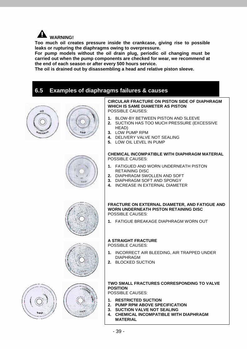
6.5 Examples of diaphragms failures & causes
CIRCULAR FRACTURE ON PISTON SIDE OF DIAPHRAGM WHICH IS SAME DIAMETER AS PISTON POSSIBLE CAUSES:
1. BLOW-BY BETWEEN PISTON AND SLEEVE 2. SUCTION HAS TOO MUCH PRESSURE (EXCESSIVE
HEAD) 3. LOW PUMP RPM 4. DELIVERY VALVE NOT SEALING 5. LOW OIL LEVEL IN PUMP
CHEMICAL INCOMPATIBLE WITH DIAPHRAGM MATERIAL POSSIBLE CAUSES:
1. FATIGUED AND WORN UNDERNEATH PISTON RETAINING DISC
2. DIAPHRAGM SWOLLEN AND SOFT 3. DIAPHRAGM SOFT AND SPONGY 4. INCREASE IN EXTERNAL DIAMETER
FRACTURE ON EXTERNAL DIAMETER, AND FATIGUE AND WORN UNDERNEATH PISTON RETAINING DISC POSSIBLE CAUSES:
1. FATIGUE BREAKAGE DIAPHRAGM WORN OUT
A STRAIGHT FRACTURE POSSIBLE CAUSES:
1. INCORRECT AIR BLEEDING, AIR TRAPPED UNDER DIAPHRAGM
2. BLOCKED SUCTION
TWO SMALL FRACTURES CORRESPONDING TO VALVE POSITION POSSIBLE CAUSES:
1. RESTRICTED SUCTION 2. PUMP RPM ABOVE SPECIFICATION 3. SUCTION VALVE NOT SEALING 4. CHEMICAL INCOMPATIBLE WITH DIAPHRAGM
MATERIAL

- 40 -
7. MANUFACTURER’S DECLARATION
Manufacturer's Declaration
Machines Directive 2006/42/CE (Attachment II point B)
Idromeccanica Bertolini S.p.A. declares under its sole responsibility that the pump series:
- TRIAL- PA - PA/S- PPS - POLY
With the serial number __________ (To be filled in by purchaser according to identification label)
- is manufactured to be incorporated in a machine or to be assembled with other equipment to form a machine provided for by Directive 2006/42 ICE;
- The producer of the machine, that incorporates the pump, is the only one responsible of the accordance in every point to these Directive standards. Therefore Idromeccanica Bertolini S.p.A. declares that the above pump must not be put into operation up to the machine in which it will be built-in will be identified and will be declared in compliance with the Directive standards 2006/42 ICE. Reggio Emilia, 10.10.2011
Luigi Quaretti ( Managing Director- Idromeccanica Bertolini S.p.A)
- 41 -
8. LIMITED WARRANTY
The liability of the manufacturer under the period of warranty (12 months from date of manufacturer’s shipment) is limited to the replacement of the parts that, upon examination, appear in Bertolini’s satisfaction to have been defective in material or workmanship. This warranty is valid only when the fault is ascertained by its technicians, it shall not apply to any pump which have been repaired or altered to adversely affect the performance or reliability of the pump. This warranty does not apply to malfunctions caused by fault or negligence of the buyer or third party, to the improper use of the pump, to failures reported to the manufacturer after the warranty period has expired, or to the normal wear of the component parts of the products such as seals, cups, O-Rings, valves, etc. Costs of labour, packages and transport are at the Buyer’s charges. Products, after receipt of written factory approval, must be returned complete with all parts and not tampered. Otherwise warranty is void. This warranty is subject to the following conditions: - Pump must be used within the specifications indicated in this manual and in the
manual of the machine where the pump is installed. A safety valve must be correctly installed in the system.
- The warranty is void if pump is operating without oil in the crankcase. - Protect pump from freezing. Do not store in area with freezing conditions. Drain
completely of pumped fluid. Flush with antifreeze. Do not store or operate in excessively high temperature areas or without proper ventilation.
- The warranty is void if installation is not correct. - The warranty is void if the recommended maintenance instructions are not
observed. - Different uses of the pump than the ones mentioned in the paragraph “Intended
Use”. - The warranty is void if the pump use does not conform to the specific current
safety standards and if the machine incorporating the pump is without CE marking.
- Use of non-original spare parts or even not suited for the pump model. USE OF OTHER THAN BERTOLINI PARTS VOIDS THE WARRANT Y. ANY PRODUCT MUST BE RETURNED FREE BERTOLINI FACTORY . PARTS RETURNED MUST HAVE FACTORY APPROVAL DOCUMENTA TION PRIOR TO RETURN.