8903134 rev a rb10 rotary dispense system equipmen
TRANSCRIPT

1
EQUIPMENTOperation Manual
Loctite RB10 Rotary Dispense SystemPart Number 1635546

2
Table of Contents
1 Please Observe The Following 3
1.1 Emphasized Sections 31.2 For Your Safety1.3 Inspection 31.4 Items Supplied 41.5 Features 4
2 Description 4
2.1 Control Panel 42.2 Integration Panel 5
3 Technical Data 5
4 Installation 6
5 Operation 7
5.1 Theory of Operation 75.2 Controller Set Up 85.3 Mounting Plate 105.4 Valve and Syringe Dispenser Integration 11
5.4.1 Light Cure, CA and VA10 Valves 115.4.2 Stationary Valves 115.4.3 Syringe or Cartridge Dispensing 12
5.5 Slide Adjustment 135.6 Reservoir Low Level Control 13
6 Troubleshooting 14
7 Care and Maintenance 14
8 Accessories 15
9 Wiring Schematic 15
10 Warranty 16

3
1 Please Observe The Following
1.1 Emphasized Sections
Warning!Refers to safety regulations and requires safety measures that protect the operator orother persons from injury or danger to life.
Caution!Emphasizes what must be done or avoided so that the unit or other property is notdamaged.
Notice:Gives recommendations for better handling of the unit during operation oradjustment as well as for service activities.
1.2 For Your Safety
For safe and successful operation of the unit, read these instructionscompletely. If the instructions are not observed, the manufacturer can assume noresponsibility.
Do not expose the connecting cable to heat, oil, or sharp edges.
Make sure the Unit stands stable and secure.
Use only original equipment replacement parts.
Always disconnect the power supply before servicing the unit.
Observe general safety regulations for the handling of chemicals such asLoctite® adhesives and sealants. Observe the manufacturer’s instructions as statedin the Material Safety Data Sheet (MSDS).
While under warranty, the unit may be repaired only by an authorized Loctite servicerepresentative.
1.3 Unpacking and Inspection
Carefully unpack the Loctite® RB10 Rotary Dispense System and examine theitems contained in the carton. Inspect the unit for any damage that might haveoccurred in transit. If such damage has occurred, notify the carrier immediately.Claims for damage must be made by the consignee to the carrier and should bereported to the manufacturer.

4
1.4 Items supplied
(1) Rotary Dispense System(1) Foot Switch(1) Power Supply with Cord(1) Instruction Manual
1.5 Features
Integrated Solution –plug and play with Loctite valves, reservoirs, andSyringe Systems
Digital Control of rotation, dispense start, dispense stop and delays Adjustable height, position, angle of dispense, and advance slide speed Reservoir low-level interface with cycle interruption and display message Part position sensing allows orientation of adhesive bead start and end Threaded and non threaded mounting holes for fixtures Operator lockout for supervisory control of settings Dispense valve and syringe mounting hardware available
2 Description
The Loctite® RB10 Rotary Dispense System is a fully integrated system used fordispensing adhesives onto parts in a circular or arc pattern. It will control a syringe system,cartridge, or dispense valve without requiring a separate valve controller. Internallysynchronized operation of an advancing slide, turntable, and dispense timer makes for easyand repetitive placement of the adhesive. The set-up is simple, using only preset distanceand rotation speed adjustment. No complex programming required!
2.1 Control Panel (Front of Controller)

5
2.2 Integration Panel (Back of Controller)
3 Technical Data
Attribute ValueDispense Pattern Circles or Arcs in a Circular PatternSlide Stroke 0 –2”(0 –50 mm)Rotation Range 0 –999 DegreesRotation Speed 5 to 55 RPMMaximum Part Height 12”(305 mm)Maximum Part Diameter 18”(475 mm)Maximum Part Weight 6 lbs (2.7 kg)
Width 12”(305 mm)Depth 8¾”(222 mm)
Dimensions
Height 22”(559 mm) Minimum25”(635 mm) Maximum
Weight 18.5 lb (8.4 kg)Air Input* Clean, dry air not to exceed 125 psig (8.5 bar),
and filtered with a maximum of 50 micronPower Supply: 110 –230 V / 50 –60 Hz
Internal: 24 VDC
* If the required air quality is not available, install a Loctite®
filter regulator. In the US order a5 m filter using part number 985397. In Europe or Asia, order a 10 m filter using partnumber 97120.

6
4 Installation
Before using the tool for the first time check it carefully for signs of externaldamage. If any shipping damage is found DO NOT USE THE TOOL - return it toyour supplier immediately.
1. Assemble the stand to the main control unit by attaching the vertical mounting pole (thelonger bar supplied) into the vertical support bracket on the control of the unit. Tightenthe M4 from the side of the support bracket to secure the vertical mounting pole.
2. Assemble the slide assembly to the stand.3. Secure the slide assembly by tightening the M6 screw on the slide assembly bracket.4. Connect the Cylinder Extend and Cylinder Retract Air hoses to the Cyl Extend
and Cyl Retract ports on the back of the unit.5. Connect the Advance Slide Cable to the Advance Slice Limit Switch connector
of the back of the unit.6. Plug the power adapter with cord into the “24VDC”input on the back of the controller and
into the wall socket.
Notice: The power adapter has auto ranging power function that can be usedwith either 110 or 220V and 50 or 60 Hz.
7. Connect the foot switch, or PLC start signal cable, to the “Start Switch XS1”connector onthe back of the controller.
8. Connect the air input line to the Air Input fitting using 6mm O.D. pneumatic tubing (notsupplied).
9. Turn on the local air supply. This must be a minimum of 80 psi and a maximum of 125psi.
Warning! When the air is connected, the slide may retract. Be sure to keepyour hands and other objects clear of the slide before connecting the air.
Caution! Clean, dry, filtered air must be used. If it is not, the solenoids in thecontroller will be fouled over time. If the required air quality is not achieved,install a Loctite® filter regulator. In the US order a 5 m filter using Part Number985397. In Europe or Asia, order a 10 m filter using Part Number 97120.

7
5 Operation
5.1 Theory of Operation
1. After turning on the unit, press the footswitch or ENTER button to activate thesystem.
2. The advancing slide will start to extend and the rotary disc will start to rotate withthe preset speed.
3. The advancing slide will activate the proximity sensor when it reaches the presetposition.
4. The start of disc rotation, or the locator pin reaching the proximity sensor (inhoming mode), will trigger the rotation distance counter and the unit will start todispense for preset dispensing time. Use of the homing mode ensures that eachdispense start will be at the same point.
5. After the dispensing timer has reached the preset dispense time, the advancing slidewill retract and the rotary disc will be stopped.
6. The dispense start position “DS Position”determines how far the disc will rotatebefore starting to dispense. This ensures the rotation has reached a constant speedwhen dispense begins.
7. The “Off Delay”feature determines how long the disc will continue to rotate afterthe dispense has stopped. This allows product remaining on the tip of the dispenserto be transferred to the part after the dispense stops, prior to retracting.
8. The reservoir low level sensor setting disables the start signal and displays “Alarm:RESERVOIR LOW LEVER.” The Low Level state can be manually overriddenallowing the system to cycle by pressing the ENTER button, however the alarm willcontinue to be displayed and the system will not cycle using a footswitch or PLC.
8
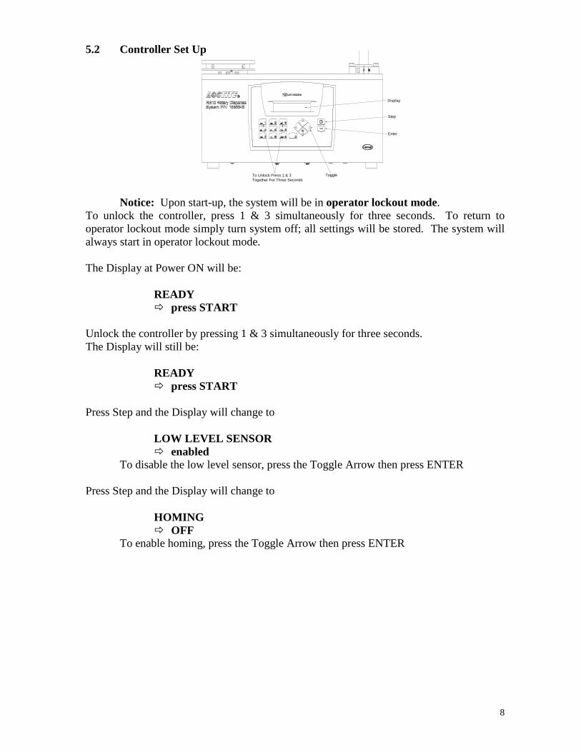
5.2 Controller Set Up
Display
Step
Enter
To Unlock Press 1 & 3Together For Three Seconds
Toggle
Notice: Upon start-up, the system will be in operator lockout mode.To unlock the controller, press 1 & 3 simultaneously for three seconds. To return tooperator lockout mode simply turn system off; all settings will be stored. The system willalways start in operator lockout mode.
The Display at Power ON will be:
READY press START
Unlock the controller by pressing 1 & 3 simultaneously for three seconds.The Display will still be:
READY press START
Press Step and the Display will change to
LOW LEVEL SENSOR enabled
To disable the low level sensor, press the Toggle Arrow then press ENTER
Press Step and the Display will change to
HOMING OFF
To enable homing, press the Toggle Arrow then press ENTER

9
Press Step and the Display will change to
Speed: 10 RPMDist: 90 degTo change the speed (revolutions per minute), type the desired speed with key pad,then press ENTERTo change the distance (in degrees) that product will dispense, type the desireddistance using the key pad, then press ENTER
Notice: The distance setting determines how far the rotation motor receives powerand is intended to be an aid in initial set up not as an absolute setting of rotation. Higherspeed setting and heavier part weights create momentum that will cause mounting plate tocarry beyond the preset degrees in a repeatable fashion.
Press Step and the Display will change to
DS Position: 0OFF Delays: 0.0To set the Dispense Start position (how far the disc will rotate before dispensestarts) type the desired distance, in degrees, then press ENTERTo set the desire off delay (how long in seconds the disc will rotate after dispensestops, type the desired time then press ENTER
Press Step and the Display will change to
READY press START
You have completed Controller Set Up. The Controller will remain unlocked until poweris turned off.
Notice: The settings can be tested without exiting mode by pressing 1 & ENTER.This will start a cycle.
Changes can be made by pressing STEP key until you get to the desired parameter.To save the changes and exit Program Mode, simply turn the power off.

10
5.3 Mounting Plate
The drawing below shows the RB10 Rotary Dispense System mounting plate. Thisthrough holes on the mounting plate can be used for fixture alignment and the threaded ¼-20 holes can be used to secure the fixture.

11
5.4 Valve and Syringe Dispenser Integration
The Loctite® RB10 Rotary Dispense System is designed to be used with syringes, cartridges,single acting product valves and double acting product valves. To integrate these dispensesystems please use the following instructions:
5.4.1 98009 Light Cure, 98013 Cyanoacrylate and VA10 Micro Dispense ValvesMust be purchased separately: Mounting Rail –P/N 98328 Mounting Bracket –P/N 98326 Mounting Bracket –P/N 1638885 Pressure Reservoir
- P/N 982726, Bond-A-Matic reservoir, 0-15 psi for use with adhesives with <3,000 cPs viscosity.- P/N 982727, Bond-A-Matic reservoir, 0-100 psi for use with adhesives with >3,000 cPs viscosity.
1. Insert the 4mm tube plug in the upper “Dispense Out”(normally closed) connection.2. Add the dispense tip onto the valve.3. Secure the mounting rail to the advance slide using the M4 screws provided.4. Slide the mounting bracket over the mounting rail on the slide assembly and secure it in
position with the white nylon thumbscrew.5. Manually pull the slide down to the fully extended position.6. Slide the valve into the mounting bracket and secure it using the black thumbscrews.7. Adjust the height and position of the mounting bracket to the approximate position desired.
To adjust the position, loosen the screws on the clamp blocks counter clockwise, set theposition and then secure by turning the screws clockwise.
Caution! It is important to ensure that the dispense tip will not crash with themounting plate, fixture or part. Please ensure that the height is set to avoid crashes.
8. Connect the air inlet on the valve to the upper “Dispense Out”on the back of the controllerusing the 4mm air line tubing supplied with the valve.
5.4.2 97113 and 97114 Stationary ValvesMust be purchased separately: Mounting Rail –P/N 98328 Mounting bracket –P/N 98327 Pressure Reservoir
- P/N 982726, Bond-A-Matic reservoir, 0-15 psi for use with adhesives with <3,000 cPs viscosity.- P/N 982727, Bond-A-Matic reservoir, 0-100 psi for use with adhesives with >3,000 cPs viscosity.- P/N 982720, Bond-A-Matic reservoir, 0-15 psi, with low level sensor.- P/N 982723, Bond-A-Matic reservoir, 0-100 psi, with low level sensor.
1. Using 4mm tubing supplied with the valve, connect both the upper “Dispense Out”(normally closed) and lower “Dispense Out”(normally open) connections from the valveto the back of the controller.
2. Add the dispense tip to the valve.3. Secure the mounting rail to the advance slide using the screws provided with the bracket.4. Slide the mounting bracket over the mounting rail on the slide assembly and secure it in
position with the white nylon thumbscrew.5. Manually pull the slide down to the fully extended position.6. Slide the valve into the mounting bracket and secure it using the black thumbscrews.

12
7. Adjust the height and position of the mounting bracket to the approximate positiondesired. To adjust the position, loosen the screws on the clamp blocks counter clockwise,set the position and then secure by turning the screws clockwise.
Caution! It is important to ensure that the dispense tip will not crash with themounting plate, fixture or part. Please ensure that the height is set to avoidcrashes.
5.4.3 Syringe or Cartridge DispensingMust be purchased separately:
Loctite Part NumberSyringe CartridgeAccessory
10 ml 30 ml 55 ml 300 mlSyringe Dispenser (Required) 883976 883976 883976 8839763 ¾”Mounting Rail (required) 98328 98328 98328 98328Mounting Bracket (required) 98316 98316 98316 98318Syringe Adapter (required) 98320 N/A N/A N/ADispense Tip Connectors (required) N/A N/A N/A 982644
97233Clear Syringe Barrel Kit (optional) 97207 97244 98314 N/ABlack Syringe Barrel Kit (optional) 97263 97264 98315 N/A
1. Refer to the operation manual of the syringe dispenser for setup instructions.2. Connect the syringe dispenser to the system with XS2 cable part number 989432 (need
to purchase separately).3. Insert the 4mm tube plug in the both the upper “Dispense Out”(normally closed) and lower
“Dispense Out”(normally open) connections.4. Add the dispense tip onto the syringe or cartridge. For some cartridges, it will be
necessary to install the cartridge adapter Part No. 982644 and luer lock adapter Part No.97233 before connecting the dispense tip.
5. Secure the mounting rail to the advance slide using the M4 screws provided.6. Slide the mounting bracket over the mounting rail on the slide assembly and secure it in
position with the white nylon thumbscrew.7. Manually pull the slide down to the fully extended position.8. Adjust the height and position of the mounting bracket to the approximate position
desired. To adjust the position, loosen the screws on the clamp blocks counter clockwise,set the position and then secure by turning the screws clockwise.
9. Slide the syringe or cartridge into the mounting bracket and secure it using the blackthumbscrews.
Caution! It is important to ensure that the dispense tip will not crash with themounting plate, fixture or part. Please ensure that the height is set to avoidcrashes.

13
5.5 Slide Adjustments
The speed controls on the slide can be adjusted to increase or decrease the speed that theslide advances or retracts. The speed should be set so that the slide moves at a controlledrate. This may need to be adjusted to account for more weight on the slide or to change theslide advance / retract time.
5.6 Reservoir Low Level Control
5.6.1 Disabling the Low Level Function1. In Set Up mode (see section 5.2) set Low Level Sensor to “Disabled.”
5.6.2 Enabling the Low Level Function1. Connect the 9 pins D-sub female (XS2 Low Lev) cable the to the Low Level Sensor
(XS2) Connector.2. In Set Up mode (see section 5.2) set Low Level Sensor to “Enabled.”
Notice: When a Reservoir Low Level state occurs during a cycle, the cycle willcomplete and the display will read “Alarm: RESERVOIR LOW LEVER.” The LowLevel setting disables the start signal.
Notice: In run mode, the Low Level state can be manually overridden allowing thesystem to cycles by pressing the ENTER button. Pressing the ENTER button will cycle theunit, however the alarm will continue to be displayed and the system will not cycle using afootswitch or PLC.
Notice: In Set Up mode, pressing the ENTER button will clear the Low Level statefor one cycle fully disabling the alarm and allowing use of the foot switch or PLC.
3. After eliminate the Low Level state, pressing ENTER will run another cycle andreset the Low Level alarm. The Low Level alarm can also be re-set by turning thesystem off after eliminating the Low Level state.
Adjust Slide AdvanceRate Here
Adjust Slide RetractRate Here

14
6 Troubleshooting
Before proceeding with any repair or maintenance operation disconnect thetool from the main electricity supply.
Symptom Possible Corrective Action(s)
Plug the unit inThe “POWER”does not turn“ON” Set the “POWER”button “ON”position
1. Confirm that the “Air Input”is connected
2. Confirm that the air supply is 80-125 psi.
The system will not pressurize.
3. Confirm that the “Dispense Out”fittings are properly connected orplugged.
Mounting plate rotates furtherthan distance setting.
Higher speeds and part weights will cause the mounting plate to carrybeyond the distance setting. The distance setting is intended for referencepurposes only as an aid to initial set up.
The slide is advancing orretracting too fast or slow.
The slide advance and retract rate should be set so that the slide moves at acontrolled rate. The factory default is for the full slide stroke to takeapproximately 0.5 seconds. If this needed to be adjusted, see Section 5.5for instructions.
1. Confirm that the air supply is pressurized and at 80-125 psi.The disc will not stop rotatingand the display reads“Homing… ”ORDisplay read "Dispenser in wait"
2. Confirm that the advancing slide moves down when the cycle starts.
1. Check that XS2 cable between the reservoir and the RB10 is connected.The “Reservoir Low LevelAlarm Light”(1) does not work 2. Check that Low Level Sensor Switch setting is in the “enabled”state.
1. Check the pneumatic connection.The dispense valve does notdispense 2. Check the pneumatic supply.
7 Care and Maintenance
7.1 CareThis unit should be stored in a level, dry location at ambient condition out of directsunlight.
7.2 MaintenanceTo minimize wear of the slide assembly, periodically apply several drops of light machineoil to the slide rods, manually advance and retract the slide several times then remove theexcess lubricant using a rag.
Warning! Be sure to release the pressure and shut of the pressure supply beforelubricating the slide rods.
Notice: Clean, dry, filtered air must be used. If it is not, the solenoids on thecontroller will be fouled over time.
Notice: If the required air quality is not achieved, install a Loctite® filter regulator.In the US order a 5 m filter using Part Number 985397. In Europe or Asia, order a 10 mfilter using Part Number 97120.

15
8 Accessories
Syringe Dispenser Accessories:
Loctite Part NumberSyringe CartridgeAccessory
10 ml 30 ml 55 ml 300 mlSyringe Dispenser (Required) 883976 883976 883976 8839763 ¾”Mounting Rail (required) 98328 98328 98328 98328Mounting Bracket (required) 98316 98316 98316 98318Syringe Adapter (required) 98320 N/A N/A N/ADispense Tip Connectors (required) N/A N/A N/A 982644
97233Clear Syringe Barrel Kit (optional) 97207 97244 98314 N/ABlack Syringe Barrel Kit (optional) 97263 97264 98315 N/A
Additional Mounting Hardware:
Description Item Number
98009 and 98013 Valve Mounting Bracket 98326
97113 and 97114 Valve Mounting Bracket 98327
VA10 Valve Mounting Bracket 1638885
3 3/4 inch mounting rail with two cap screws 98328
8 3/4 inch mounting rail with two cap screws 98329
C Rail Kit for Mounting Brackets 98331
986300 Poppet Valve Mounting Bracket Kit 98406
98084 or 98520 Valve Mounting Bracket Kit 98441
9 Wiring Schematic

16
10 Warranty
Henkel expressly warrants that all products referred to in this Instruction Manual for 1635546 Loctite RB10Rotary Dispense System (hereafter called “Products”) shall be free from defects in materials andworkmanship. Liability for Henkel shall be limited, as its option, to replacing those Products which are shownto be defective in either materials or workmanship or to credit the purchaser the amount of the purchase pricethereof (plus freight and insurance charges paid therefor by the user). The purchaser’s sole and exclusiveremedy for breach of warranty shall be such replacement or credit.
A claim of defect in materials or workmanship in any Products shall be allowed only when it is submitted inwriting within one month after discovery of the defect or after the time the defect should reasonably havebeen discovered and in any event, within (12) months after the delivery of the Products to the purchaser. Thiswarranty does not apply to perishable items, such as fuses. No such claim shall be allowed in respect ofproducts which have been neglected or improperly stored, transported, handled, installed, connected,operated, used or maintained. In the event of unauthorized modification of the Products including, whereproducts, parts or attachments for use in connection with the Products are available from Henkel, the use ofproducts, parts or attachments which are not manufactured by Henkel, no claim shall be allowed.
No Products shall be returned to Henkel for any reason without prior written approval from Henkel. Productsshall be returned freight prepaid, in accordance with instructions from Henkel.
NO WARRANTY IS EXTENDED TO ANY EQUIPMENT WHICH HAS BEEN ALTERED, MISUSED,NEGLECTED, OR DAMAGED BY ACCIDENT.
EXCEPT FOR THE EXPRESS WARRANTY CONTAINED IN THIS SECTION, HENKEL MAKES NOWARRANTY OF ANY KIND WHATSOEVER, EXPRESS OR IMPLIED, WITH RESPECT TO THEPRODUCTS.
ALL WARRANTIES OF MERCHANTABILITY, FITNESS FOR A PARTICULAR PURPOSE, ANDOTHER WARRANTIES OF WHATEVER KIND (INCLUDING AGAINST PATENT OR TRADEMARKINFRINGEMENT) ARE HEREBY DISCLAIMED BY HENKEL AND WAIVED BY THE PURCHASER.
THIS SECTION SETS FORTH EXCLUSIVELY ALL OF LIABILITY FOR HENKEL TO THEPURCHASER IN CONTRACT, IN TORT OR OTHERWISE IN THE EVENT OF DEFECTIVEPRODUCTS.
WITHOUT LIMITATION OF THE FOREGOING, TO THE FULLEST EXTENT POSSIBLE UNDERAPPLICABLE LAWS, HENKEL EXPRESSLY DISCLAIMS ANY LIABILITY WHATSOEVER FORANY DAMAGES INCURRED DIRECTLY OR INDIRECTLY IN CONNECTION WITH THE SALE ORUSE OF, OR OTHERWISE IN CONNECTION WITH, THE PRODUCTS, INCLUDING, WITHOUTLIMITATION, LOSS OF PROFITS AND SPECIAL, INDIRECT OR CONSEQUENTIAL DAMAGES,WHETHER CAUSED BY NEGLIGENCE FROM HENKEL OR OTHERWISE.
Henkel CorporationOne Henkel WayRocky Hill, CT 06067-3910
Henkel Canada Corporation2225 Meadowpine BoulevardMississauga, Ontario L5N 7P2
Henkel Capital, S.A. de C.V.Calzada de la Viga s/n Fracc. Los LaurelesLoc. Tulpetlac, C.P. 55090Ecatepac de Morelos, Edo. de México
Henkel CorporationAutomotive / Metals HQ32100 Stephenson Hwy.Madison Heights, MI 48071
Henkel Ltda.Rua Karl Huller, 136 –Jd.Canhema 09941-410Diadema/SP, Brazil www.loctite.com
® and ™ designate trademarks of Henkel Corporation or its affiliates. ® = registered in the U.S. and elsewhere. © Henkel Corporation,2009. All rights reserved. Data in this operation manual is subject to change without notice.Manual P/N: 8903134, Rev A, Date: 08/13/2012