9- ijmite - design and analysis of propeller blade using ... ijmite... · design and analysis of...
TRANSCRIPT

Impact Factor (JCC): 0.9458 - This article can be downloaded from www.bestjournals.in
DESIGN AND ANALYSIS OF PROPELLER BLADE USING
CATIA & ANSYS SOFTWARE
SUDHAKAR UPPALAPATI 1, K.V.RAGHAVULU 2 & KRANTHI KUMAR SINGAM 3
1,2Associate Professor, Department of Mechanical, MarriLaxman Reddy
Inst of Tech and Management, Hyderabad, Telangana, India 3PG Student, Department of Mechanical, Mother Theressa College of
Engineering & Technology, Peddapally, Karimnagar, India
ABSTRACT
Fiber strengthened composites have found wide spread use within naval applications recently. Boats and under
drinking water vehicles like torpedoes Submarines etc. Torpedoes which are made for deeper and moderate depths require
minimization of structural weight for increasing payload, performance/velocity and operating range for the purpose
Aluminium alloy casting can be used for the fabrication of propeller cutting blades. In current years the increased
dependence on the light-weight structural aspect with acoustic insulation, has resulted in use of fiber content reinforced
multi covering composite propeller. Today's work provides out the structural evaluation of any CFRP (carbon fibre
reinforced cheap) propeller cutting tool which proposed to displace the Metal propeller cutting tool. Propeller is put
through an exterior hydrostatic pressure on either area of the cutting blades with regards to the operating depth and
movement across the propeller also bring about differential hydrodynamic pressure between face and again surfaces of
rotor blades. The propeller edge is modeled and designed so that it can with stand the static fill distribution and locating the
strains and deflections for both aluminium and carbon fiber content reinforced cheap materials. This work in essence
handles the modeling and design research of the propeller cutting tool of your torpedo because of its durability. A propeller
is intricate 3D model geometry. This involves top quality modeling CATIA software can be used for making the cutter
model. This record includes brief information regarding Fiber Reinforced Plastic material materials and the features of
using amalgamated propeller over the traditional metallic propeller. Through the use of ANSYS software modal research
and static structural evaluation were completed for both light weight aluminum and CFRP
KEYWORDS: Aluminum, Carbon Fiber Reinforced Plastic, CATIA, ANSYS
INTRODUCTION
Sea propeller is an element which forms the main part of boats since it offers the mandatory propulsion. Fiber
strengthened plastics are thoroughly found in the manufacturing of varied structures like the sea propeller. The
hydrodynamic areas of the look of composite sea propellers have fascinated attention because they're important in
predicting the deflection and performance of the propeller cutter.For making an optimized sea propeller you have to
comprehend the variables that effect the hydro-dynamic action. Since propeller is a intricate geometry, the examination
could be achieved only by making use of numerical tools. Most sea propellers are constructed of metal materials such as
bronze or metallic. The features of replacing metal with an FRP composite are that the latter is corrosion-resistant and
lighter. Another important advantage is usually that the deformation of the composite propeller can be manipulated to
BEST: International Journal of Management, Information Technology and Engineering (BEST: IJMITE) ISSN (P): 2348-0513, ISSN (E): 2454-471X, Vol. 4, Issue 4, Apr 2016, 83-96 © BEST Journals

84 Sudhakar Uppalapati, K.V.Raghavulu & Kranthi Kumar Singam
Index Copernicus Value: 3.0 – Articles can be sent to [email protected]
boost its performance. Propellers always turn at a regular speed that maximizes the efficiency of the engine unit. When the
dispatch sails at the designed swiftness, the inflow perspective is near its pitch viewpoint. When the dispatch sails at a
lesser acceleration, the inflow position is smaller. Hence, the strain on the propeller rises as the dispatch speed lowers. The
propulsion efficiency is also low when the inflow perspective is definately not the pitch perspective. In case the pitch
perspective can be reduced when the inflow perspective is low, the efficiency of the propeller can be better then.
Traditionally marine propellers are constructed of manganese-nickel-aluminum-bronze (MAB) or nickel-aluminum-bronze
(NAB) for superior corrosion resistance, high-yield strength, reliability, and affordability. Moreover metallic propellers are
put through corrosion, cavitations destruction; tiredness induced breaking and has relatively poor acoustic damping
properties that can result in noises credited to structural vibration. Moreover, composites will offer the potential benefits
associated with reduced corrosion and cavitations damage, improved fatigue performance, lower noise, improved material
damping properties, and reduced lifetime maintenance cost. In addition the load-bearing fibers can be aligned and stacked
to reduce fluttering also to increase the hydrodynamic efficiency.
Design of Propeller Blade
• Open CATIA V5 R16
• Close the Product Window
• Start – Mechanical Design – Wireframe and Surface Design – Enter Part Name as Propeller Blade – OK
• Now we are in a surface modeling - Select Top (XY) plane – Sketch tool
• Now we are in sketcher workbench - Draw a circle with 60 dia – Exit workbench
• Extrude it with 50 mm on both sides total 100 mm height as shown
Figure 1: Propeller Design
• Create a point on the right plane at a distance of 30 mm from vertical 4 mm from horizontal as , Create the helix
with 92 mm height and 276 pitch as shown
Figure 2: Helix Created
Design and Analysis of Propeller Blade using Catia & Ansys Software 85
Impact Factor (JCC): 0.9458 - This article can be downloaded from www.bestjournals.in
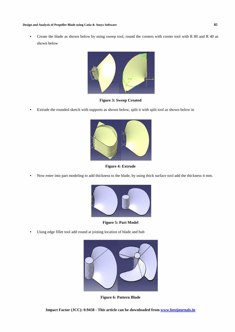
• Create the blade as shown below by using sweep tool, round the corners with corner tool with R 80 and R 40 as
shown below
Figure 3: Sweep Created
• Extrude the rounded sketch with supports as shown below, split it with split tool as shown below in
Figure 4: Extrude
• Now enter into part modeling to add thickness to the blade, by using thick surface tool add the thickness 4 mm.
Figure 5: Part Model
• Using edge fillet tool add round at joining location of blade and hub
Figure 6: Pattern Blade
86 Sudhakar Uppalapati, K.V.Raghavulu & Kranthi Kumar Singam
Index Copernicus Value: 3.0 – Articles can be sent to [email protected]
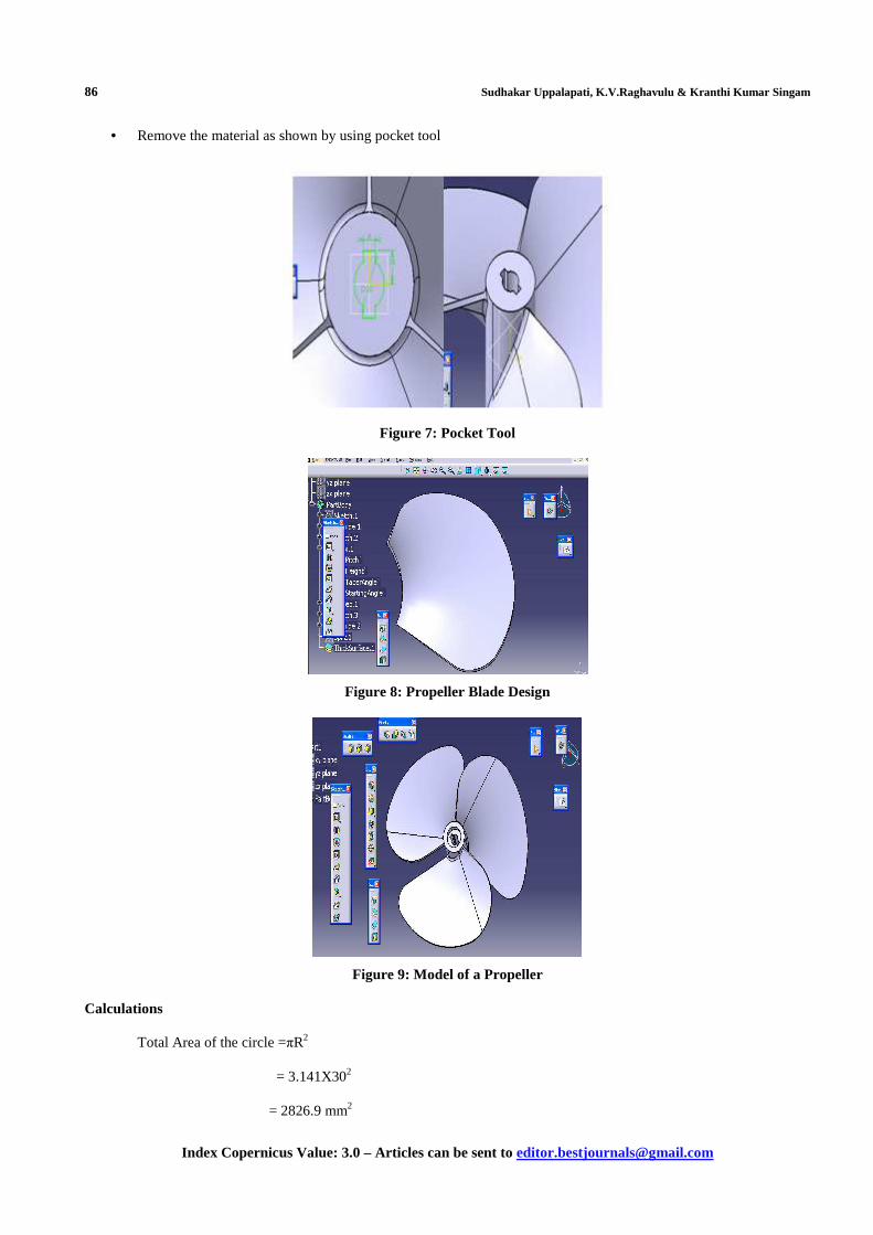
• Remove the material as shown by using pocket tool
Figure 7: Pocket Tool
Figure 8: Propeller Blade Design
Figure 9: Model of a Propeller
Calculations
Total Area of the circle =πR2
= 3.141X302
= 2826.9 mm2

Design and Analysis of Propeller Blade using Catia & Ansys Software 87
Impact Factor (JCC): 0.9458 - This article can be downloaded from www.bestjournals.in
Total Blade Area = π r2 X DAR
= 2826.9X0.92
=2600.748 mm2
(DAR = TBA/TAC = 2600.748/2826.9=92 %)
Relationship between Pitch & Pitch Angle
Formula: Pitch = 2π r X Tan a
Where: a = pitch angle and r = radius andπ=3.14159
Pitch Angle = 120
Pitch = 326.318 mm
Speed = (RPM/Ratio)(Pitch/C)(1-S/100)
Speed = (1000/0.5X326.316/1)(1-0/100) assumeRatio=1/2, =39.1581 km/hr Slip(S)=0
Boat Speed VB = 24.3317 mile/hr; (1 mile = 1.609344 kilometers)
The thrust (T) is equal to the mass flow rate (.m) times the difference in velocity (V).
T = m x (VB – VA)
Mass Flow Rate per hr (m) = area of blade x speed of the boat
= 2600.74 x 10-6 x39.1581 x 103
= 101.840 m 3 /hr
Thrust (T) = m x (VB – VA) = 101.840 x 39.1581 x 10 3
= 3987860.9 N
= 3.98 MN
Properties of Carbon Fiber Reinforced Plastic (Compare To Metals)
• High flexibility
• High tensile strength
• Low weight
• High resistance
• High temperature tolerance
• Low thermal expansion
• Highest strength-to-weight ratio

88 Sudhakar Uppalapati, K.V.Raghavulu & Kranthi Kumar Singam
Index Copernicus Value: 3.0 – Articles can be sent to [email protected]
Tensile Strength & Youngs Modulas
Figure 10: Tensile Strength Comparison & Youngs Modulus
Resistivity & Thermal Expansion Coefficient
Figure 11: Resistivity & Thermal Expansion Coefficient
Modal Analsys
Alumnium
Frequency Table
Table 1
S.NO MODE FREQUENCY 1 1 98.199 2 2 399.22 3 3 490.05 4 4 611.38 5 5 817.33 6 6 1064.9

Design and Analysis of Propeller Blade using Catia & Ansys Software 89
Impact Factor (JCC): 0.9458 - This article can be downloaded from www.bestjournals.in
Figure 12: Analysis for Aluminum
Carbon Fiber Reinforced Plastic
Frequency Table
Table 2
S.NO MODE FREQUENCY 1 1 107.27 2 2 437.25 3 3 543.44 4 4 679.99 5 5 907.28 6 6 1182.4
Figure 13: Analysis of CFRP
Default Mesh
Aluminium
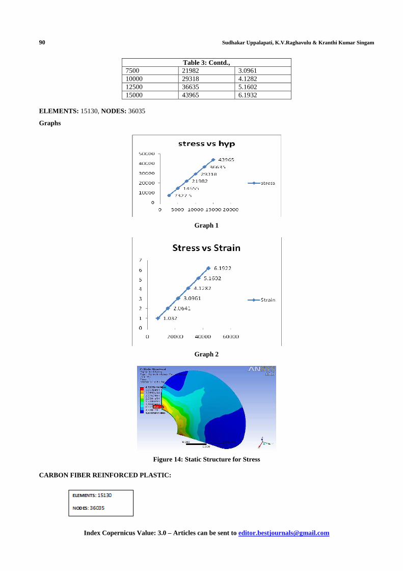
Table 3
Hydrostatic pressure
Stress Strain
2500 7327.5 1.032 5000 14655 2.0641
90 Sudhakar Uppalapati, K.V.Raghavulu & Kranthi Kumar Singam
Index Copernicus Value: 3.0 – Articles can be sent to [email protected]
Table 3: Contd., 7500 21982 3.0961 10000 29318 4.1282 12500 36635 5.1602 15000 43965 6.1932
ELEMENTS: 15130, NODES: 36035
Graphs
Graph 1
Graph 2
Figure 14: Static Structure for Stress
CARBON FIBER REINFORCED PLASTIC:

Design and Analysis of Propeller Blade using Catia & Ansys Software 91
Impact Factor (JCC): 0.9458 - This article can be downloaded from www.bestjournals.in
Table 4 Carbon fiber reinforced plastic
Hydrostatic
Pressure Stress Strain
2500 7138.2 0.7435 5000 14276 1.4871 7500 21414 2.2306 10000 28552 2.9742 12500 35698 3.7177 15000 42828 4.4613
Graphs
Graph 3
Graph 4
Figure 15: Static Structure for Equivalent Stress
92 Sudhakar Uppalapati, K.V.Raghavulu & Kranthi Kumar Singam
Index Copernicus Value: 3.0 – Articles can be sent to [email protected]
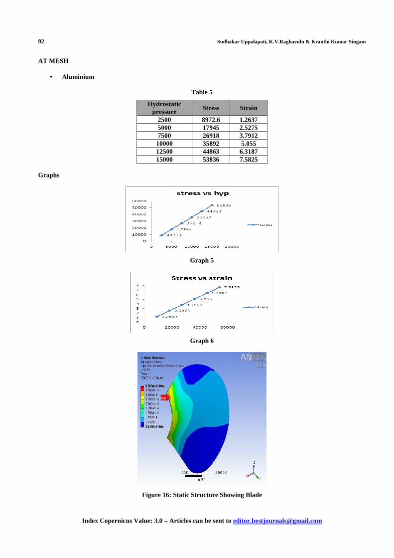
AT MESH
• Aluminium
Table 5
Hydrostatic pressure
Stress Strain
2500 8972.6 1.2637 5000 17945 2.5275 7500 26918 3.7912 10000 35892 5.055 12500 44863 6.3187 15000 53836 7.5825
Graphs
Graph 5
Graph 6
Figure 16: Static Structure Showing Blade
Design and Analysis of Propeller Blade using Catia & Ansys Software 93
Impact Factor (JCC): 0.9458 - This article can be downloaded from www.bestjournals.in
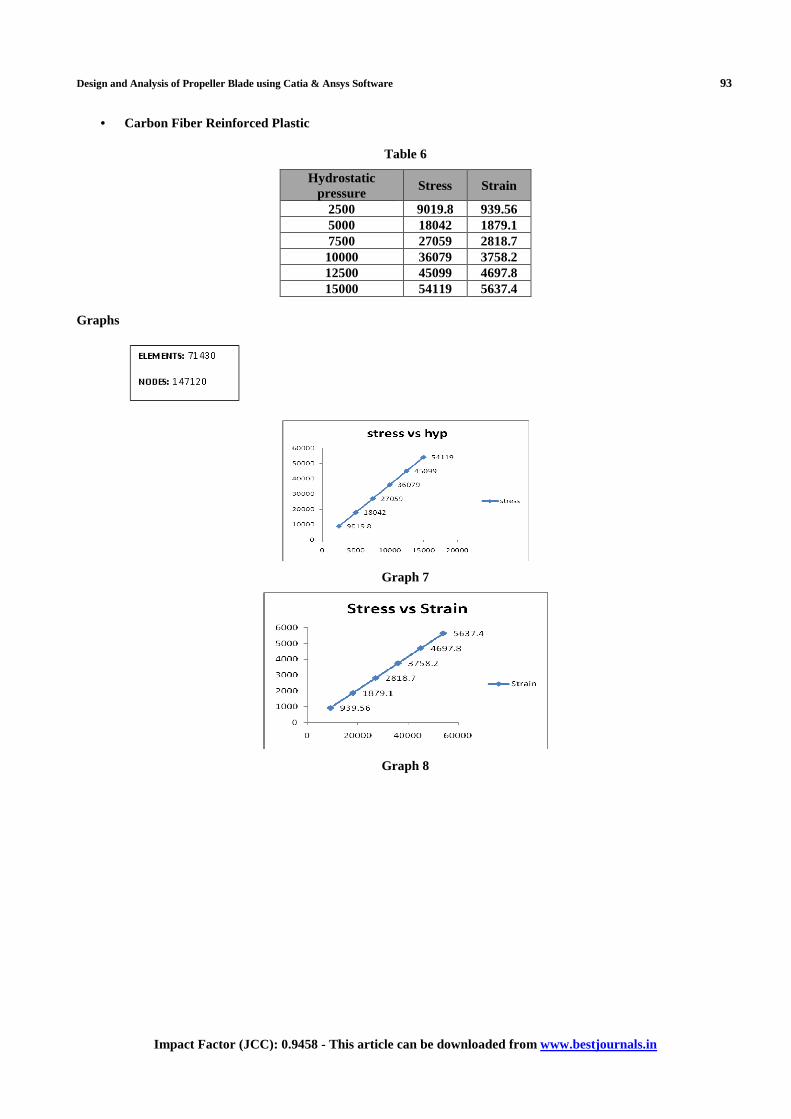
• Carbon Fiber Reinforced Plastic
Table 6
Hydrostatic pressure
Stress Strain
2500 9019.8 939.56 5000 18042 1879.1 7500 27059 2818.7 10000 36079 3758.2 12500 45099 4697.8 15000 54119 5637.4
Graphs
Graph 7
Graph 8

94 Sudhakar Uppalapati, K.V.Raghavulu & Kranthi Kumar Singam
Index Copernicus Value: 3.0 – Articles can be sent to [email protected]
Figure 17: Static Structure in Ansys
AT MESH
• Aluminium
Table 7
1.ALUMINIUM
Hydrostatic Pressure
Stress Strain
2500 8434.7 1188 5000 16869 2376 7500 25304 3564 10000 33739 4752 12500 42174 5940 15000 50608 7128
Graphs
Graph 9
Graph 10
Design and Analysis of Propeller Blade using Catia & Ansys Software 95
Impact Factor (JCC): 0.9458 - This article can be downloaded from www.bestjournals.in
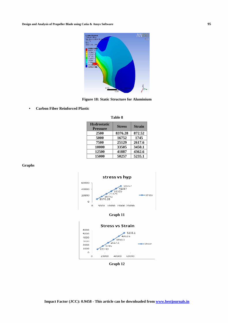
Figure 18: Static Structure for Aluminium
• Carbon Fiber Reinforced Plastic
Table 8
Hydrostatic Pressure
Stress Strain
2500 8376.28 872.52 5000 16752 1745 7500 25129 2617.6 10000 33505 3450.1 12500 41887 4362.6 15000 50257 5235.1
Graphs
Graph 11
Graph 12
96 Sudhakar Uppalapati, K.V.Raghavulu & Kranthi Kumar Singam
Index Copernicus Value: 3.0 – Articles can be sent to [email protected]
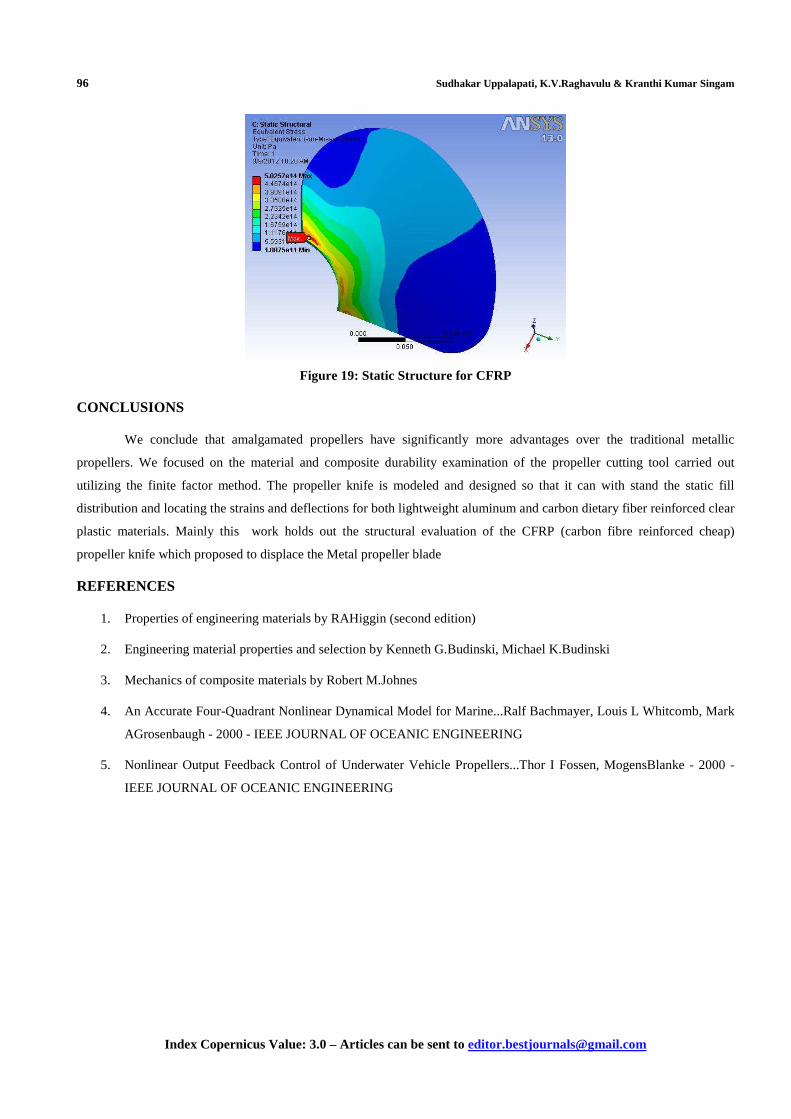
Figure 19: Static Structure for CFRP
CONCLUSIONS
We conclude that amalgamated propellers have significantly more advantages over the traditional metallic
propellers. We focused on the material and composite durability examination of the propeller cutting tool carried out
utilizing the finite factor method. The propeller knife is modeled and designed so that it can with stand the static fill
distribution and locating the strains and deflections for both lightweight aluminum and carbon dietary fiber reinforced clear
plastic materials. Mainly this work holds out the structural evaluation of the CFRP (carbon fibre reinforced cheap)
propeller knife which proposed to displace the Metal propeller blade
REFERENCES
1. Properties of engineering materials by RAHiggin (second edition)
2. Engineering material properties and selection by Kenneth G.Budinski, Michael K.Budinski
3. Mechanics of composite materials by Robert M.Johnes
4. An Accurate Four-Quadrant Nonlinear Dynamical Model for Marine...Ralf Bachmayer, Louis L Whitcomb, Mark
AGrosenbaugh - 2000 - IEEE JOURNAL OF OCEANIC ENGINEERING
5. Nonlinear Output Feedback Control of Underwater Vehicle Propellers...Thor I Fossen, MogensBlanke - 2000 -
IEEE JOURNAL OF OCEANIC ENGINEERING