neuform–3-blade-variable pitch propeller r2 series...
TRANSCRIPT

NEUFORM–3-Blade-Variable Pitch Propeller R2 Series
Assembly and Maintenance Manual
for Rotax 912, 912S and 914
Manual control by hand lever (H)
or electric constant speed control (ECS)
Date: 28 April 2010
Your NEUFORM-Distributor:

NEUFORM 3-Blade Variable Pitch Propeller, R2-SeriesAssembly and Maintenance Manual
Date: www.neuform-propellers.com 28 April 2010 - All rights reserved - Page 2
Table of Contents
Description ................................................................................................... 2
Part 1: Assembly .........................................................................3
Scope of delivery .......................................................................................... 3 a) Propeller ............................................................................................... 3 b) Manual Control ("H") ............................................................................... 4 c) Electric Constant Speed Control ("ECS")..................................................... 4
Assembly of Hub and Blades ......................................................................... 5
Assembly of the Control Mechanism ........................................................... 18 a) Manual Control ("H") ............................................................................. 18
Assembly of the Lever Unit..................................................................... 18 Filling the System with Hydraulic Fluid ..................................................... 19 Adjustment of the Propeller and Pre-Tension of the Hydraulic System .......... 21
b) Electric Constant Speed Control ("ECS")................................................... 22 Assembly of the Lever Unit..................................................................... 22 Assembly of Controller and Cables .......................................................... 23 Adjustment of the Propeller.................................................................... 24
Static RPM Test........................................................................................... 26
Checks ........................................................................................................ 28 After the first flight..................................................................................... 28 Further checks........................................................................................... 28
Part 2: Maintenance and Care....................................................29
Re-Lubrication ............................................................................................ 29
List of amendments
Date Amendment 15 February 2008 Re-edition after TM-08-01 28 April 2010 - Detailed definition of further checks removed. Reference to
operating manual in chapter checks added instead in order to avoid redundant definition. - Switch off-Note added to Static RPM Test

NEUFORM 3-Blade Variable Pitch Propeller, R2-SeriesAssembly and Maintenance Manual
Date: www.neuform-propellers.com
Description
Preliminary Note
This document is an Assembly and Maintenance Manual and is for use by technically qualified persons only; it does not replace the Operation Manual, which is delivered with the propeller. Although the assembly of the propeller is very straightforward, we strongly recommend having it done by qualified personnel only.
Prior to first operation of the propeller, please read the appropriate operation manual! In this manual, the “upper” half of the hub is meant to be the part of the hub furthest away from the engine, and the “lower” half of the hub, the part nearest to the engine.
Part 1: Assembly
Scope of delivery
The delivery includes the propeller (a) and the control (b) or (c).
a) Propeller
1. Hub with all screw joints and mounted reset unit 2. Spacer with shear pins 3. 3 propeller blades, complete with bearings, adjusting rings and sliding nuts 4. Control rod
28 April 2010 - All rights reserved - Page 3
NEUFORM 3-Blade Variable Pitch Propeller, R2-SeriesAssembly and Maintenance Manual
Date: www.neuform-propellers.com
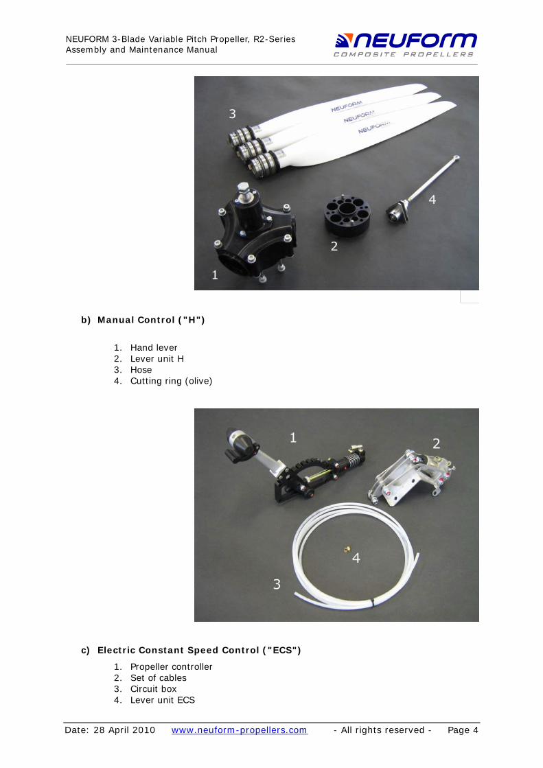
b) Manual Control ("H")
1. Hand lever 2. Lever unit H 3. Hose 4. Cutting ring (olive)
c) Electric Constant Speed Control ("ECS")
1. Propeller controller 2. Set of cables 3. Circuit box 4. Lever unit ECS
28 April 2010 - All rights reserved - Page 4

NEUFORM 3-Blade Variable Pitch Propeller, R2-SeriesAssembly and Maintenance Manual
Date: www.neuform-propellers.com
Assembly of Hub and Blades
CAUTION: The engine's propeller flange, spinner, spacer and propeller hub must be free from grease, oil and other smear. For that, appropriate cleaning agents must be used. Let dry before assembly.
First, assemble the lower half of the hub including spinner base plate and spacer. Please consult your aircraft's manufacturer for the size of the spacer. It may occur that the spacer, different from the picture below, must be assembled between flange and base plate (picture below).
28 April 2010 - All rights reserved - Page 5

NEUFORM 3-Blade Variable Pitch Propeller, R2-SeriesAssembly and Maintenance Manual
Date: www.neuform-propellers.com
next, prepare the control rod (picture) ...
The control rod is completely pre-assembled. Prior to installation it must be checked to ensure that the "pitch-limit-pack" of the correct dimension (thickness) has been slid on.
The "pitch-limit-pack" comprises a 4.5 mm thick aluminium spacer (5.5 mm for the older models) and depending on engine performance, additional shim rings of 0.5 mm thick each. The "pitch-limit-pack" is necessary to adjust the minimum pitch and ensure that the smallest useful pitch (setting for take off) cannot be undershot. For blade type C (CR3-V-70; CR3-V-80, CL3-V-70; CR3-V-80) the following dimensions are used:
28 April 2010 - All rights reserved - Page 6
NEUFORM 3-Blade Variable Pitch Propeller, R2-SeriesAssembly and Maintenance Manual
Date: www.neuform-propellers.com
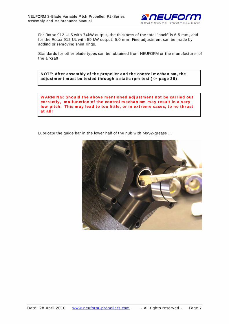
For Rotax 912 ULS with 74kW output, the thickness of the total "pack" is 6.5 mm, and for the Rotax 912 UL with 59 kW output, 5.0 mm. Fine adjustment can be made by adding or removing shim rings. Standards for other blade types can be obtained from NEUFORM or the manufacturer of the aircraft. NOTE: After assembly of the propeller and the control mechanism, the adjustment must be tested through a static rpm test (-> page 26).
WARNING: Should the above mentioned adjustment not be carried out correctly, malfunction of the control mechanism may result in a very low pitch. This may lead to too little, or in extreme cases, to no thrust at all!
Lubricate the guide bar in the lower half of the hub with MoS2-grease ...
28 April 2010 - All rights reserved - Page 7

NEUFORM 3-Blade Variable Pitch Propeller, R2-SeriesAssembly and Maintenance Manual
Date: www.neuform-propellers.com
... then slide the control rod together with the "pitch-limit-pack" into the lower half of the hub ...
... as far as it will go.
28 April 2010 - All rights reserved - Page 8

NEUFORM 3-Blade Variable Pitch Propeller, R2-SeriesAssembly and Maintenance Manual
Date: www.neuform-propellers.com
Rear view of the gear box.
Next prepare the propeller blades for assembly. Check first whether the locking plate of the slotted nut has been bent over:
CAUTION: Deficient locking of the groove nut may lead to blade loss during operation! Unlocking of the assembly may only be performed by authorised NEUFORM-Service-personnel!
28 April 2010 - All rights reserved - Page 9

NEUFORM 3-Blade Variable Pitch Propeller, R2-SeriesAssembly and Maintenance Manual
Date: www.neuform-propellers.com
Prior to assembly of the propeller blades, attach the sliding nuts and coat them thoroughly with MoS2-grease (picture).
Make sure that the long side of the sliding nut faces the inside (picture)
28 April 2010 - All rights reserved - Page 10

NEUFORM 3-Blade Variable Pitch Propeller, R2-SeriesAssembly and Maintenance Manual
Date: www.neuform-propellers.com
and the chamfer (bevel surface) the outside.
Also, lubricate those parts of both halves of the hub that will be in contact with the gaskets of the propeller blades and the contact surface of the adjusting link (picture).
28 April 2010 - All rights reserved - Page 11

NEUFORM 3-Blade Variable Pitch Propeller, R2-SeriesAssembly and Maintenance Manual
Date: www.neuform-propellers.com
The blades will be easy to insert. Twist the sliding nut until it faces the middle of the adjusting link, then insert the blade, sliding nut first, into the adjusting link.
Only now insert the blade with a twisting motion into its bearing surface in the hub base. Repeat for the other blades.
28 April 2010 - All rights reserved - Page 12

NEUFORM 3-Blade Variable Pitch Propeller, R2-SeriesAssembly and Maintenance Manual
Date: www.neuform-propellers.com
View after insertion of the blades.
This is the moment for a last visual check: Are all locking plates at the propeller blades locked ? Is the castle nut in adjusting link secured by a split-pin ?
If you are assembling the electric control version, just an outer "pitch-limit-pack" (green) must be added to limit the maximum setting angle.
28 April 2010 - All rights reserved - Page 13

NEUFORM 3-Blade Variable Pitch Propeller, R2-SeriesAssembly and Maintenance Manual
Date: www.neuform-propellers.com
Now the assembly of the upper half of the hub can be performed. First check whether the tensioning screw is completely undone ...
... lubricate the guide bar of the adjusting links and the contact surface of the gaskets, as previously described for the assembly of the lower half of the hub.
28 April 2010 - All rights reserved - Page 14
NEUFORM 3-Blade Variable Pitch Propeller, R2-SeriesAssembly and Maintenance Manual
Date: www.neuform-propellers.com
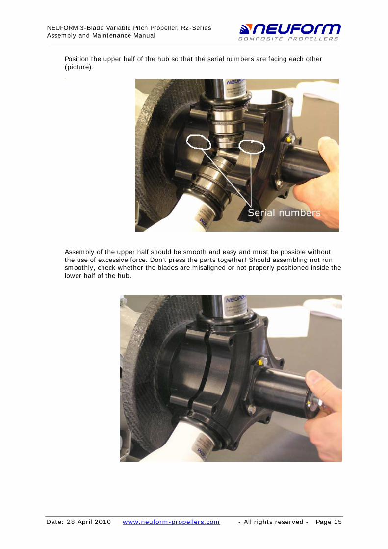
Position the upper half of the hub so that the serial numbers are facing each other (picture).
Assembly of the upper half should be smooth and easy and must be possible without the use of excessive force. Don't press the parts together! Should assembling not run smoothly, check whether the blades are misaligned or not properly positioned inside the lower half of the hub.
28 April 2010 - All rights reserved - Page 15

NEUFORM 3-Blade Variable Pitch Propeller, R2-SeriesAssembly and Maintenance Manual
Date: www.neuform-propellers.com
Install the screws with washers at both sides ...
... and tighten the screws crosswise (diametrically opposite screws) to 27 Nm.
28 April 2010 - All rights reserved - Page 16
NEUFORM 3-Blade Variable Pitch Propeller, R2-SeriesAssembly and Maintenance Manual
Date: www.neuform-propellers.com
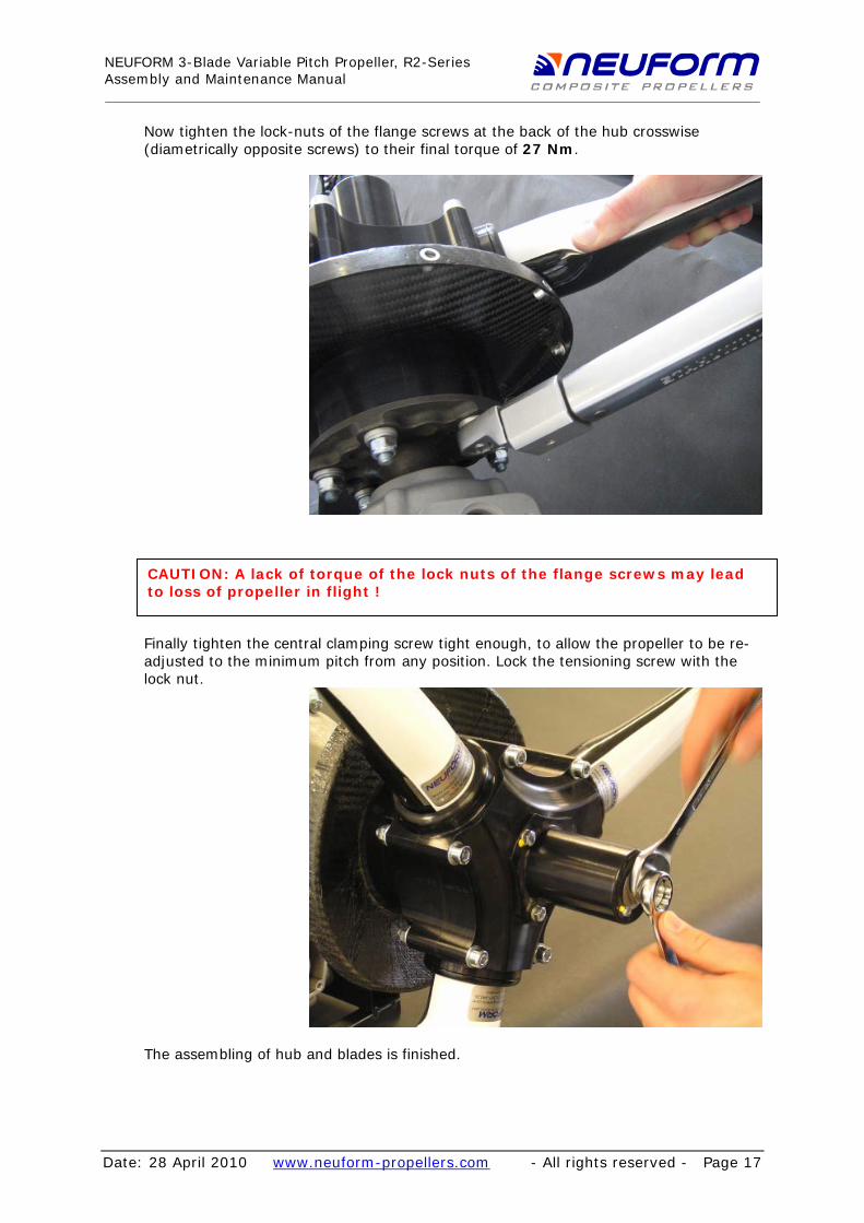
Now tighten the lock-nuts of the flange screws at the back of the hub crosswise (diametrically opposite screws) to their final torque of 27 Nm.
CAUTION: A lack of torque of the lock nuts of the flange screws may lead to loss of propeller in flight !
Finally tighten the central clamping screw tight enough, to allow the propeller to be re-adjusted to the minimum pitch from any position. Lock the tensioning screw with the lock nut.
The assembling of hub and blades is finished.
28 April 2010 - All rights reserved - Page 17
NEUFORM 3-Blade Variable Pitch Propeller, R2-SeriesAssembly and Maintenance Manual
Date: www.neuform-propellers.com
Assembly of the Control Mechanism
a) Manual Control ("H")
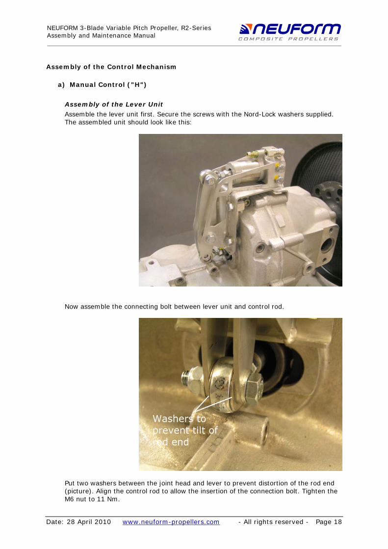
Assembly of the Lever Unit Assemble the lever unit first. Secure the screws with the Nord-Lock washers supplied. The assembled unit should look like this:
Now assemble the connecting bolt between lever unit and control rod.
Put two washers between the joint head and lever to prevent distortion of the rod end (picture). Align the control rod to allow the insertion of the connection bolt. Tighten the M6 nut to 11 Nm.
28 April 2010 - All rights reserved - Page 18
NEUFORM 3-Blade Variable Pitch Propeller, R2-SeriesAssembly and Maintenance Manual
Date: www.neuform-propellers.com
Assemble the hand lever in the cockpit. This will depend on the type of aircraft and is not included in this manual. Please refer to the manufacturer/dealer of your aircraft.
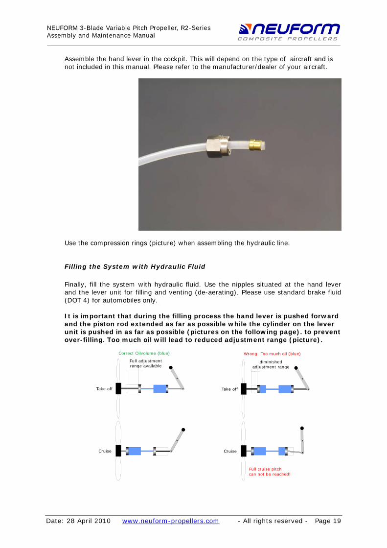
Use the compression rings (picture) when assembling the hydraulic line.
Filling the System with Hydraulic Fluid
Finally, fill the system with hydraulic fluid. Use the nipples situated at the hand lever and the lever unit for filling and venting (de-aerating). Please use standard brake fluid (DOT 4) for automobiles only. It is important that during the filling process the hand lever is pushed forward and the piston rod extended as far as possible while the cylinder on the lever unit is pushed in as far as possible (pictures on the following page). to prevent over-filling. Too much oil will lead to reduced adjustment range (picture).
Full adjustmentrange available
Take off
Correct Oilvolume (blue)
Cruise
diminished adjustment range
Take off
Cruise
Wrong: Too much oil (blue)
Full cruise pitchcan not be reached!
28 April 2010 - All rights reserved - Page 19

NEUFORM 3-Blade Variable Pitch Propeller, R2-SeriesAssembly and Maintenance Manual
Date: www.neuform-propellers.com
Bleed the system carefully of air to ensure fault-free operation.
28 April 2010 - All rights reserved - Page 20

NEUFORM 3-Blade Variable Pitch Propeller, R2-SeriesAssembly and Maintenance Manual
Date: www.neuform-propellers.com
Adjustment of the Propeller and Pre-Tension of the Hydraulic System
Basic Setting
Basic Setting is performed exclusively via settings inside the hub. Through a "pitch-limit-pack" (-> Seite 6), a batch of shim rings, which is variable in its thickness, the end position of the adjusting link inside the hub can be set securely and precisely. Such a basic setting ensures that the propeller will provide in case of any imaginable control failure enough thrust for secure continued flying.
Minimum Pitch
The dimension (thickness) of the "pitch-limit-pack" may vary depending on the type of propeller blade used. Thickness must be chosen to limit the propeller to a speed of not more than 5500 1/min during a full-throttle test on ground.
Check this with a static test (engine speed test) see page 26.
NOTE: The minimum setting angle of the blades must be limited, so that the propeller doesn't allow more than 5500 revs when a static test on ground is performed!
Maximum Pitch
The maximum setting angle depends on the travel of the lever and doesn't need to be limited with hydraulic operation.
End of Basic Settings. Fine Adjustment and Pre-Tension Fine adjustment exceeding the basic settings can be performed through the setscrew on the slave cylinder (see picture). Here, a lower maximum engine speed at take off can be easily set. Loosening of the screw ("lengthening" of the piston rod) will result in a higher pitch angle of the propeller blades and thus a lower maximum engine speed at take off. Also, lengthening of the piston rod will add a little pre-tension to the hydraulic system. This will improve the control response.
28 April 2010 - All rights reserved - Page 21

NEUFORM 3-Blade Variable Pitch Propeller, R2-SeriesAssembly and Maintenance Manual
Date: www.neuform-propellers.com
b) Electric Constant Speed Control ("ECS")
Assembly of the Lever Unit Assemble the lever unit first. Secure the screws with the Nord-Lock washers supplied. The assembled unit should look like this:
Now assemble the connecting bolt between lever unit and control rod.
28 April 2010 - All rights reserved - Page 22
NEUFORM 3-Blade Variable Pitch Propeller, R2-SeriesAssembly and Maintenance Manual
Date: www.neuform-propellers.com
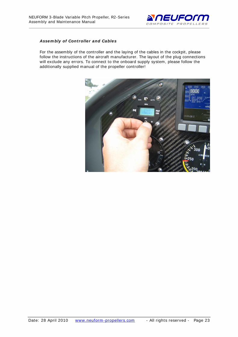
Assembly of Controller and Cables
For the assembly of the controller and the laying of the cables in the cockpit, please follow the instructions of the aircraft manufacturer. The layout of the plug connections will exclude any errors. To connect to the onboard supply system, please follow the additionally supplied manual of the propeller controller!
28 April 2010 - All rights reserved - Page 23

NEUFORM 3-Blade Variable Pitch Propeller, R2-SeriesAssembly and Maintenance Manual
Date: www.neuform-propellers.com
Adjustment of the Propeller
Basic Setting
Basic Setting is performed exclusively via settings inside the hub. Through a batch of shim rings, which is variable in its thickness, so-called "pitch-limit-packs", the end position of the adjusting link within the hub can be set securely and precisely. Such a basic setting ensures that the propeller will provide enough thrust for secure continued flying in case of any imaginable control failure.
Minimum Pitch
The thickness of the "pitch-limit-pack" may vary depending on the type of propeller blade used. Thickness must be chosen to effectively limit the propeller to a speed of not more than 5500 1/min during a full-throttle test on ground. This is checked as follows: 1. Perform a static test (engine speed test) see page 26. 2. After successful test, the limit stop for the end switch "start position" must
be set so that the switch will safely release before the mechanic limit stop inside is met. This will protect the actuating motor from mechanical overloading.
NOTE: The minimum setting angle of the blades must be limited, so that the propeller doesn't allow more than 5500 rpm when a static test on ground is performed!
Maximum Pitch (applies to electric drive only)
The chosen thickness of the outer "pitch-limit-pack" (see page 13) must assure that the propeller reaches its inner limit stop before the possible maximum of the adjusting range of the electric drive (lever unit) is exceeded. To check this, perform the following test: 1. Bring the limit stop for the end switch "cruising position" at the lever unit as
far forward as possible. 2. Remove the top screw of the adjusting lever (similar to static test, page 26). 3. Move the propeller manually by turning the blades until it meets the initial
stop.
4. Ideally, the adjusting lever will move almost to the switchpoint (click) of the end switch. Should it exceed the switchpoint, the front "pitch-limit-pack" (page 13) will have to be thickened by adding shim rings. Repeat the test.
28 April 2010 - All rights reserved - Page 24
NEUFORM 3-Blade Variable Pitch Propeller, R2-SeriesAssembly and Maintenance Manual
Date: www.neuform-propellers.com
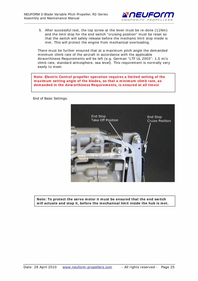
5. After successful test, the top screw at the lever must be re-done (11Nm) and the limit stop for the end switch "cruising position" must be reset so that the switch will safely release before the mechanic limit stop inside is met. This will protect the engine from mechanical overloading.
There must be further ensured that at a maximum pitch angle the demanded minimum climb rate of the aircraft in accordance with the applicable Airworthiness Requirements will be left (e.g. German “LTF UL 2003”: 1,5 m/s climb rate, standard atmosphere, sea level). This requirement is normally very easily to meet.
Note: Electric Control propeller operation requires a limited setting of the maximum setting angle of the blades, so that a minimum climb rate, as demanded in the Airworthiness Requirements, is ensured at all times!
End of Basic Settings.
Note: To protect the servo motor it must be ensured that the end switch will actuate and stop it, before the mechanical limit inside the hub is met.
28 April 2010 - All rights reserved - Page 25

NEUFORM 3-Blade Variable Pitch Propeller, R2-SeriesAssembly and Maintenance Manual
Date: www.neuform-propellers.com
Fine Adjustment
If required, the limit stops of the end switches at the lever unit can be used for fine adjustment, which can limit the range of the setting angle even further, but never extend it. Here, requirements like, for example, a lower take off engine speed or further limiting of the maximum cruising pitch can be easily set. To protect the servo motor it must be ensured that the end switch will actuate and stop the motor, before the mechanical limit inside the hub is met.
Static RPM Test
Check for correct assembly and proper adjustment of the "pitch-limit-pack" by performing a static rpm test. The "pitch-limit-pack" inside the hub is intended to prevent the pitch reducing below the smallest useable pitch. This is to ensure that, in the event of any imaginable control failure, enough thrust will be produced to ensure safe flight.
Note: It is important that the connecting bolt between lever and piston rod of the slave cylinder is removed prior to the static test, to simulate failure of the control mechanism.
Note: In case of electric actuator it is necessary either to switch off the propeller controller or to unplug the servo motor during the test in order to avoid unintended servo motor action.
It is recommended to secure the aeroplane on the ground during the static test to prevent movement. Start the engine and rev it slowly up to full throttle. (The engine should be warm). The engine speed reached should not exceed 5500 rpm (Rotax 912/914). Additionally, it is recommended not to go below 5300 1/min, but make sure to obtain the recommendations of the aircraft manufacturer as well! Should the engine speed be too low, one 0.5 mm washer from the "pitch-limit-pack" must be removed. If it is too high, a washer should be added.. Replace the connecting bolt after the successful static test and tighten it to 11 Nm.
IMPORTANT: After each change of the "pitch-limit-pack" a new static test must be performed!
28 April 2010 - All rights reserved - Page 26

NEUFORM 3-Blade Variable Pitch Propeller, R2-SeriesAssembly and Maintenance Manual
Date: www.neuform-propellers.com28 April 2010 - All rights reserved - Page 27

NEUFORM 3-Blade Variable Pitch Propeller, R2-SeriesAssembly and Maintenance Manual
Date: www.neuform-propellers.com
Checks
After the first flight
NOTE: After the first flight after each new assembly of the propeller hub, the tightening torque of the flange bolts must be checked (see page 17). Do not unscrew to do that!
This is necessary to counteract possible torque settlement effects.
Further checks
For further checks please refer to chapter checks in the current version of the operating manual.
28 April 2010 - All rights reserved - Page 28

NEUFORM 3-Blade Variable Pitch Propeller, R2-SeriesAssembly and Maintenance Manual
Date: www.neuform-propellers.com
Part 2: Maintenance and Care Maintenance and care of the propeller is done according to the Operation Manual. The only maintenance item discussed here is "re-lubrication", as it requires partial disassembling.
Re-Lubrication
First, the tensioning screw (page 17) is undone and the upper half of the hub and the blades are disassembled (See assembling in reverse order pages 12-17). Use the standard lubricant MoS2-grease. Inject the lubricant between inner and outer ring of the roller-bearing and then rotate the bearing a couple of times manually to distribute the lubricant. Do not unlock the locking plate of the round nut. The preset tension of the bearing will thus be retained.
WARNING: It is strongly recommended not to undo the bearings! Deficient locking of the round nut may lead to loss of the blade during operation! Incorrect setting of the pre-tension may lead to malfunction. Only authorised NEUFORM-Service-personnel may undo the round nut or work on the roller bearings!
Re-assemble blades and upper half of the hub (Page 9-17). Lubricate all lube points with fresh grease as shown in this manual.
28 April 2010 - All rights reserved - Page 29