920 illumination...specs for structural supports for highway signs, luminaires, and traffic signals,...
TRANSCRIPT

NMDOT Design Manual 920-1
920 Illumination
920.1 General
The primary function of illumination (roadway lighting) is to
supplement vehicle headlights by providing additional visibility of
the roadway and related features including roadway access points.
Illumination is also provided to enhance the visual perception of
conditions or features that require additional pedestrian or cyclist
alertness during the hours of darkness. Roadway lighting should
not be expected to produce a daytime equivalent in terms of
visibility or illumination.
In some situations, roadway lighting is considered for reasons other
than the nighttime enhancement of traffic operations. A local
agency may find benefit in lighting for promoting a community,
reducing crime and vandalism, or providing public comfort and
convenience during times of darkness. In these cases, lighting may
be considered where the local governmental entity finds sufficient
benefits to pay an appreciable percentage of the cost of, or wholly
finance, the installation, maintenance, and operation of the lighting
facilities.
920.2 References
The following references are used in the planning, design,
construction, and operation of roadway lighting installed on state
highways. Conformance with federal and state laws and codes is
required. Any reference to a design guide, code, law, or
requirement refers to its latest version.

920-2 Illumination
The NMDOT is not currently
using ANSI/IES RP-8-14,
which classifies luminaires in
terms of BUG rating.
920.2.1 Federal/State Laws and Codes
17.4.2 New Mexico Administrative Code (NMAC), Requirement
for Occupancy of State Highway System Right-of-Way by
Utility Facilities.
18.31.6 NMAC, State Highway Access Management
Requirements.
New Mexico Statutes Annotated (NMSA) Sections 74-12-1 to
74-12-10, Night Sky Protection Act.
920.2.2 Design Guidance
American Association of State Highway and Transportation
Officials (AASHTO) Load and Resistance Factor Design (LRFD)
Specs for Structural Supports for Highway Signs, Luminaires,
and Traffic Signals, current edition.
AASHTO Roadway Lighting Design Guide, 2005.
A Policy on the Geometric Design of Highways and Streets
(Green Book), AASHTO, current edition.
American National Standard Practice for Roadway Lighting
ANSI/IESNA RP-8-14, Illuminating Engineering Society of
North America (IESNA), 2005.
Design Guide for Roundabout Lighting, DG-19-08, IES, 2008.
Guidelines for the Implementation of Reduced Lighting on
Roadways, Federal Highway Administration (FHWA), 2014.
Highway Safety Manual, AASHTO, current edition.
Manual on Uniform Traffic Control Devices for Streets and
Highways (MUTCD), United States Department of
Transportation (USDOT), FHWA, current edition.
National Electrical Code (NEC), National Fire Protection
Association (NFPA), current edition.
NFPA 502: Standard for Road Tunnels, Bridges, and Other
Limited Access Highways, NFPA, current edition.
NFPA 780: Standard for the Installation of Lightning Protection
Systems, NFPA, current edition.
New Mexico Department of Transportation (NMDOT) Standard
Drawings.

NMDOT Design Manual 920-3
NMDOT Standard Specifications for Highway and Bridge
Construction, current edition.
Roadway Lighting Handbook, FHWA, August 2012.
Roadside Design Guide, AASHTO, current edition.
920.3 Definitions
Terms used in the discussion of the planning and design of lighting
systems are defined below.
Adaptive lighting system - A design methodology in which
roadway lighting illumination levels and times of operation are
adjusted based on the needs of the roadway’s users.
Associated facilities - Parallel or connecting travel ways or
access points used by pedestrians or other non-motorized
transportation modes, such as bicycles.
Average initial horizontal illuminance - The average level of
horizontal illuminance on the pavement area of a traveled way
at the time the lighting system is installed (when lamps are new
and luminaires are clean), expressed in average footcandles for
the pavement area.
Average maintained horizontal illuminance - The average
level of horizontal illuminance on the roadway pavement when
the output of the lamp and luminaire is diminished by the
maintenance factors, expressed in average footcandles for the
pavement area.
Ballast - A device used with an electric discharge lamp to obtain
the necessary circuit conditions (voltage, current, and wave
form) for starting and operating.
Bracket or mastarm - An attachment to a lighting standard or
other structure used for the support of a luminaire.
BUG rating - The backlight, uplight, and glare of a luminaire.
The NMDOT is not currently using this criteria for its roadway
lighting.
Conventional lighting - A highway lighting system in which
the luminaires are typically mounted no higher than 50 feet.

920-4 Illumination
Cross road - A street crossing at an access controlled facility or
intersecting street, either at-grade or grade separated, to a
roadway.
Equipment factor (EF) - Relates the actual field performance of
a new luminaire to laboratory performance data. Generally, an
EF of 0.90 to 0.95 is used for roadway lighting computations.
Footcandle - The illuminance on a surface one square foot in
area on which there is a uniformly distributed light flux of one
lumen.
Glare - The optical sensation produced by luminance within the
visual field that is sufficiently greater than the luminance to
which the eyes are adapted to cause annoyance or discomfort
(discomfort glare), or loss in visual performance and visibility
(disability glare).
Illuminance - The density of the luminous flux incident on a
surface. It is the quotient of the luminous flux divided by the
area of the surface when the latter is uniformly illuminated.
Illuminance is not observer or pavement dependent.
Illuminance method - A method of roadway lighting design
that determines the amount of light incident on the roadway
surface.
Iso-footcandle diagram - This diagram is available from the
manufacturer of the light source and shows the horizontal
footcandles on the pavement surface at various points away
from the source. Mounting height must be known to properly
use the diagram.
Lamp - A generic term for a man-made source of light that is
produced either by incandescence or luminescence.
Lamp lumen depreciation factor (LLD) - A factor that indicates
the decrease in a lamp’s initial lumen output over time. For
design calculations, the initial lamp lumen value is reduced by a
LLD to compensate for the anticipated lumen reduction. This
factor is usually found in test data or established by the state.
LED street light - A luminaire that uses light emitting diodes
(LEDs) as its light source.

NMDOT Design Manual 920-5
Lighting project categories - Defined as freeways, access
controlled routes other than freeways, non-access controlled
routes, intersections, pedestrian facilities, railroad grade
crossings and park and ride facilities.
Lighting standard - The pole with or without bracket or
mastarm used to support one or more luminaire.
Lighting unit - The assembly of pole or standard with bracket
and luminaire.
Lumen - A unit of measure of the quantity of light (luminous
flux).
Luminaire - A complete lighting unit consisting of a lamp or
lamps together with the parts designed to distribute the light, to
position and protect the lamps, and to connect the lamps to the
power supply.
Luminaire dirt depreciation (LDD) - Light loss depreciation
due to accumulated dirt.
Luminance - The luminous intensity of a surface in a given
direction per unit of projected area of the surface as viewed
from the direction (measured in footlamberts).
Luminance method - A method of roadway lighting design
which determines how bright the road is by determining the
amount of light reflected from the pavement in the direction of
the driver.
Luminous efficacy - The quotient of the total luminous flux
delivered from a light source divided by the total power input
to the light source. It is expressed in lumens per watt.
Luminous flux - The perceived power of light, measured in
lumens.
Maintenance - Includes replacement of damaged lighting
standards and luminaires, lamp replacement due to lamp lumen
depreciation, continuous electrical service, and future relocation
of roadway luminaires and standards.
Maintenance factor (MF) - A combination of factors used to
denote the reduction of the illumination for a given area after a
period of time compared to the initial illumination on the same
area (MF = EF + LLD + LDD).

920-6 Illumination
Mounting height - The vertical distance between the roadway
surface and the center of the apparent light source of the
luminaire.
Public entity - The federal government or any federal
department or agency, a Native American tribe or pueblo or
nation, the state, a county, municipality, public corporation or
public district of this state and any school district or state
educational institution in this state.
Slip base - A pole support designed to resist wind and vibration
loads while safely releasing upon impact from any direction.
Spacing - The distance between successive lighting units
measured along the centerline of the roadway.
Urban, suburban, and rural conditions - Urban conditions refer
to those areas adjacent to an urban roadway, as classified by the
NMDOT. Suburban conditions exist in areas contiguous to
urban areas, as classified by the NMDOT. Rural conditions refer
to all other areas or as areas adjacent to rural roadways, as
classified by the NMDOT.
Users - Includes vehicle operators and other transportation
modes which use the roadway and pedestrian ways within
NMDOT right-of-way.
Veiling luminance - A luminance superimposed on the retinal
image that reduces contrast. It is this veiling effect produced by
bright sources or areas in the visual field that results in
decreased visual performance and visibility.
Visibility - The quality or state of being perceivable by the eye.
In outdoor applications, visibility is defined in terms of the
distance at which an object can just be perceived by the eye.
920.4 Procedures
The lighting system design should be accomplished in a logical
sequence as outlined below:
1. Analyze for lighting warrants and obtain recommendation for
installation from NMDOT.
2. Obtain a Letter of Intent to Maintain from the local
governmental entity having jurisdiction.

NMDOT Design Manual 920-7
3. Determine availability and location of electric service from local
electrical service provider.
4. Using lighting analysis software, determine luminaire type,
mounting height, and spacing.
5. Document lighting analysis to show that lighting criteria are met.
6. Consider roadside safety for pole placement, and set final pole
locations.
7. Select lighting equipment.
8. Size, design, and document the calculations for the electrical
distribution system.
9. Complete plans, specifications, and estimates.
10. Obtain final approval and complete maintenance agreement
with local government entity.
920.4.1 Warranting
The warrants in this section are for the purpose of justifying the
installation of roadway lighting systems on state highways in New
Mexico from a financial standpoint. It is generally recognized that
roadway lighting contributes to improving safety, traffic
movements, and general roadway use in urbanized areas. In rural
areas, however, roadway lighting is normally confined to unique
conditions where there are conflicting traffic movements that can be
better delineated by nighttime illumination. In all cases, the
justification of lighting on state highways requires the concurrence
of the NMDOT and the local governing entity (agency having
jurisdiction of the particular roadway section).
Warranting conditions have been established to provide a basis to
justify the installation of fixed-source lighting from a financial
standpoint. Lighting warrant studies on candidate state highway
sections shall be conducted in accordance with AASHTO’s
Roadway Lighting Design Guide.
Lighting warrant studies may be performed by a public entity, the
entity’s qualified consultant engineer, or NMDOT staff. The District
Engineer or designee and the General Office Traffic Section shall be
responsible for the review of these studies and recommend
candidate improvements.

920-8 Illumination
Meeting a warrant does not in
itself mean that lighting must
be installed.
Meeting a warrant does not in itself mean that lighting must be
installed.
920.4.1.1 Freeway Lighting
1. Complete freeway interchange lighting is considered to be
warranted based on the criteria contained in the latest edition of
AASHTO’s Roadway Lighting Design Guide, under the section
titled “Complete Interchange Lighting.”
2. Partial interchange lighting is considered to be warranted based
on the criteria contained in AASHTO’s Roadway Lighting
Design Guide, under the section titled “Partial Interchange
Lighting.”
3. Continuous freeway lighting is considered to be warranted
based on the criteria described in the latest edition of
AASHTO’s Roadway Lighting Design Guide under the section
entitled “Continuous Freeway Lighting.”
4. Lighting at freeway ramps, gores, and cross roads is considered
warranted if either 1 or 2 above is satisfied.
920.4.1.2 Lighting for Access Controlled Routes other
than Freeways
1. Interchange lighting is considered to be warranted under the
same criteria as in Section 1, 2, or 4 above.
2. Intersection and roadway section lighting is considered to be
warranted based on the criteria for sections described below.
920.4.1.3 Lighting for Non-Access Controlled Routes
Lighting may be provided for highway sections based on the
following guidelines.
1. If replacement lighting is needed on highway sections that
currently have continuous lighting, it should be upgraded to
current appropriate AASHTO guidelines.
2. On new roadway sections or where no continuous lighting
exists, continuous lighting may be provided if one of the
following conditions is satisfied:
a. The subject section satisfies volume criteria as shown in
Exhibit 920-1.
NMDOT Design Manual 920-9
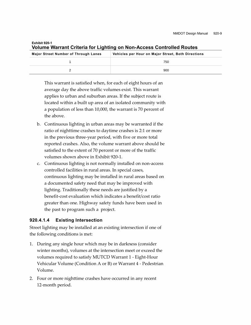
Exhibit 920-1
Volume Warrant Criteria for Lighting on Non-Access Controlled Routes
Major Street Number of Through Lanes Vehicles per Hour on Major Street, Both Directions
1 750
2 900
This warrant is satisfied when, for each of eight hours of an
average day the above traffic volumes exist. This warrant
applies to urban and suburban areas. If the subject route is
located within a built up area of an isolated community with
a population of less than 10,000, the warrant is 70 percent of
the above.
b. Continuous lighting in urban areas may be warranted if the
ratio of nighttime crashes to daytime crashes is 2:1 or more
in the previous three-year period, with five or more total
reported crashes. Also, the volume warrant above should be
satisfied to the extent of 70 percent or more of the traffic
volumes shown above in Exhibit 920-1.
c. Continuous lighting is not normally installed on non-access
controlled facilities in rural areas. In special cases,
continuous lighting may be installed in rural areas based on
a documented safety need that may be improved with
lighting. Traditionally these needs are justified by a
benefit-cost evaluation which indicates a benefit/cost ratio
greater than one. Highway safety funds have been used in
the past to program such a project.
920.4.1.4 Existing Intersection
Street lighting may be installed at an existing intersection if one of
the following conditions is met:
1. During any single hour which may be in darkness (consider
winter months), volumes at the intersection meet or exceed the
volumes required to satisfy MUTCD Warrant 1 - Eight-Hour
Vehicular Volume (Condition A or B) or Warrant 4 - Pedestrian
Volume.
2. Four or more nighttime crashes have occurred in any recent
12-month period.

920-10 Illumination
3. When a traffic signal or an intersection flashing beacon is
installed.
4. Where a combination of sight distance, or horizontal or vertical
curvature of the roadway, channelization, or other factors
constitute a potentially confusing or unsatisfactory condition
that may be improved with lighting. A project report evaluating
the need should include an investigation of the factors
constituting those conditions.
920.4.1.5 New Intersection
Per 18.31.6 NMAC, illumination should be provided at all
signalized intersections in accordance with AASHTO’s Roadway
Lighting Design Guide or as otherwise approved by the NMDOT.
Lighting may be installed at new intersections if it is forecast that
any of the warrants listed above will be satisfied within five years
after the opening of the project to traffic. Lighting should be
installed and operational before or upon the installation of a
roundabout.
920.4.1.6 Railroad Highway Grade Crossing
Lighting may be installed at railroad-highway grade crossings.
920.4.1.7 Pedestrian Facilities
Lighting for pedestrian facilities may be considered at urban or
suburban crossing locations where conflicts with vehicular traffic
constitute a potentially confusing or unsatisfactory situation. Such
situations could include crosswalk locations where a substantial
amount of documented nighttime pedestrian or bicycle activities
take place. Other locations where lighting is considered warranted
include pedestrian overpasses and tunnels.
920.4.1.8 Park-and-Ride Lots
Lighting of these facilities is desirable but not mandatory. An
evaluation should be performed to determine if it is feasible and
cost effective.
920.4.1.9 Rest Areas
Lighting should be installed at rest areas for safety and security, if
it is feasible and cost effective.

NMDOT Design Manual 920-11
920.4.1.10 Lighting Other Areas
The lighting of other areas will be considered on a case-by-case
basis and is largely dependent on the desires and needs of the
operating entity, including its willingness to provide for future
maintenance and operation of the lighting system. A study to
determine the need for lighting should include the feasibility of
providing electrical service. Special areas to be lighted may include
truck weighing stations and inspection and enforcement areas.
920.4.1.11 Lighting Based on Safety Analysis
In some circumstances, a new lighting installation may be
warranted where a safety analysis using the FHWA Highway
Safety Manual suggests that providing lighting may reduce the
incidence of crashes.
920.4.1.12 Other Considerations for Warranting Roadway
Lighting
In addition to meeting one of the warrants above, in order for a
lighting system to be considered the following two conditions must
be met:
The highway section must be within the city limits or
jurisdiction of the local government entity making a request.
The local government entity must be willing to execute an
agreement in which it agrees to provide all operating and
maintenance costs.
The warrant procedures and request for approval shall be
documented and forwarded to the NMDOT Traffic Support Section
for review and recommendation as a possible candidate for
improvements. Note that the fact that a location meets a warrant
does not obligate the NMDOT to provide funding for the requested
highway lighting project. NMDOT’s objective is to identify those
roadways that should be considered in the process of setting
priorities for the allocation of available funding for roadway
lighting projects.
920-12 Illumination
920.4.2 Design Analysis
The design of a roadway lighting system must effectively address
factors such as initial cost, maintenance, operating cost, and
provision of a uniform and adequate level of illumination for users
of the roadway. In general, the lighting layout selected is largely
dependent on local preference and maintenance capabilities (e.g.,
established rates, maintenance stockpiles). Accordingly, the design
must be coordinated with the responsible local maintaining entity
and its utility organizations. The FHWA Lighting Handbook and
the information contained in the sections below are also good
references in selecting a lighting layout. The final selection of the
lighting layout shall be approved by the NMDOT Traffic Section.
920.4.2.1 Continuous Lighting Systems
The most common type of street and highway lighting consists of
specifically designed roadway lighting luminaires mounted on
poles placed adjacent to the roadway and capable of providing
continuous illumination for the roadway over a substantial
distance.
Roadway luminaires are designed to provide an elongated lighting
pattern, longitudinally with the roadway. In addition, most
roadway luminaires also push the light pattern perpendicular to the
roadway, forming what are commonly referred to as the street-side
and the house-side along its longitudinal axis. The most important
variables affecting the design are the light source, light source size,
and mounting height selected. These variables must be matched in
the design process with the light uniformity required.
Standard urban street lighting commonly uses poles with a 30-foot
mounting height. Because of their wider roadways, freeways and
multilane divided highways require taller mounting heights. For
freeways, 40 feet is the usual mounting height because it
substantially reduces the number of poles required and is still
accessible for maintenance without highly specialized equipment.
The goal of the design should be to minimize the number of poles
while using luminaires that provide acceptable uniformity and
glare control. Reducing the number of poles can reduce initial costs
and maintenance efforts, and improve daytime aesthetics and
safety.

NMDOT Design Manual 920-13
The same luminaires and poles used for continuous lighting are
used singularly or in small groups for intersection,
partial-interchange, or spot safety lighting applications.
920.4.2.2 High-Mast Lighting
High-mast lighting implies an area type of lighting with groups of
luminaires mounted on free-standing poles at mounting heights
typically ranging from 100 to 150 feet. At these mounting heights,
several high-output luminaires develop highly uniform light
distribution. Because of its ability to illuminate a relatively large
area per single support, high-mast lighting is confined to complete
interchanges, rest areas, and parking areas, and for possible
continuous lighting on highways having wide cross sections and a
large number of traffic lanes.
The principal benefits of high-mast applications are the ability to
provide excellent uniformity of illumination and reduce glare with
a substantially smaller number of poles. Normal mounting heights
permit the use of luminaires that direct the light more downwardly
and yet maintain a large area of coverage. This distribution of light
can reduce both discomfort and disability glare, and provide better
performance under adverse weather conditions such as rain, fog, or
dust storms.
The locations benefiting most from high-mast lighting are complex
interchanges, where conventional continuous lighting of the
turning, crossing, and intersecting road and ramps can create a
confusing visual field for the driver. High-mast lighting of such an
interchange provides for the illumination of the areas between the
roadway and ramps which can provide the proper visual
perspective as in daylight conditions and improve the driver’s
ability to make advance decisions and judge distances.
High-mast lighting contributes to aesthetics and safety by reducing
the number of poles that would be required for a conventional
system and allowing poles to be located out of the recovery area
adjacent to the driving lanes. Also, their remote location eliminates
the need for maintenance vehicles to obstruct traffic on the roadway
or to have maintenance personnel work near high-speed traffic
lanes. High-mast lighting equipment, however, is more complex

920-14 Illumination
In accordance with the New
Mexico Night Sky Protection
Act, the NMDOT specifies
only full cutoff luminaires.
LED luminaires are preferred
by the NMDOT for roadway
lighting.
than conventional lighting. Because of their height, high-mast poles
require lowering devices to allow luminaire servicing, and these
require special design and maintenance considerations.
920.4.2.3 Light Sources
New factors that are having an increasing influence on roadway
lighting design include light pollution in the night environment and
the need for electrical energy conservation. The impact of stray light
on nighttime skies and its unwanted intrusion on private property
is an area of growing public sensitivity. The need for energy
conservation is not only related to its supply but also to
maintenance and operating costs, which have risen dramatically for
many local governing entities. Therefore, the designer should
consider the latest advances in lighting equipment and design and
specify roadway lighting systems that provide optimum optical
light controlled by today’s standards and that are energy efficient.
In New Mexico, where lighting is installed it shall comply with the
Night Sky Protection Act, which specifies the use of full cutoff
luminaires. A luminaire light distribution is designated as full
cutoff when there is no light at or above an angle of 90 degrees
above horizontal, and the candlepower per 1000 lamp lumens does
not numerically exceed 10 percent at an angle of 80 degrees above
horizontal.
The NMDOT primarily uses LED or high-pressure sodium (HPS)
lamps for highway lighting. While other types of lamps have been
used in the past, they are being replaced by these types of lamps.
Light-Emitting Diodes (LEDs)
The NMDOT prefers to use LED lamps for roadway lighting. LEDs
produce a directional narrow beam of light making them ideal for
traffic signals, barrier lighting, and other directional light source
applications. LED efficacies are increasing constantly, making LED
luminaires effective for all types of lighting applications. Because
LEDs are monochromatic, white light is difficult to produce unless
different colors are combined. LEDs have extremely long lives
(100,000 hours), consume very little energy, and are dimmable.

NMDOT Design Manual 920-15
HPS
HPS lamps were previously the most commonly used light source
for new installations by the NMDOT, but are now being replaced
by LEDs. However, HPS lamps are still preferred by some local
entities (specifically in southern New Mexico) for new and
replacement installations. HPS lamps provide excellent luminous
efficiency, good lumen maintenance, long life (20,000 hours), and an
acceptable color. The arc tubes of HPS lamps have a very small
diameter and are available in a wide range of lumen outputs. This
type of light source permits the use of luminaires with good optical
control for a wide range of applications.
HPS lamps do have several disadvantages. The most important is
the lack of short wavelength light such as blue and green light. As a
result, HPS lamps render color poorly, and one’s peripheral vision
under nighttime exterior lighting conditions does not respond well
to the color of HPS light. White light can be two to twenty times
more effective for peripheral vision detection than HPS. Because
short wavelength light controls the pupil, HPS lamps may cause
objects to be out of focus or fuzzy.
Metal Halide
The NMDOT no longer uses metal halide lamps for roadway
lighting.
Induction
The NMDOT is not currently using induction lamps for roadway
lighting.
920.4.2.4 Luminaire Light Distributions
The IESNA defines roadway and area lighting luminaires by their
photometric properties and distance to the half maximum candela
trace and the maximum candela value. The classifications help
designers choose the proper product for their requirements; they
are not a photometric specification but a method to group luminaire
types. Manufacturers provide precise electronic photometric data
(.ies files) for various lamp-luminaire combinations that can be used
in determining the amount and direction of luminous flux by using
lighting design software.

920-16 Illumination
The lateral classification describes the lateral light distribution with
regards to the lighted area width described as multiples of the
mounting height (MH). The width of the half-maximum candela
trace within the longitudinal distribution range (short, medium or
long) is used. These are illustrated in Exhibit 920-2.
Exhibit 920-2
Lateral Light Distribution Patterns
In addition to these types, the light distribution can also be
classified as short, medium, or long. This refers to the luminaire’s
vertical light distribution and is based on where the maximum
intensity (candela value) points to in relation to the luminaire pole.
Control of Stray Light
Disability and discomfort glare are largely a result of light emission
into the driver’s eye. For design purposes, it is necessary that
luminaires be classified according to their relative glare effects.
Luminaires may be classified according to the roadway shielding
classification system, shown in Exhibit 920-3, and categorized as full
cutoff, cutoff, semi-cutoff, and non-cutoff. In accordance with the
New Mexico Night Sky Protection Act, all luminaires must be full
cutoff luminaires. A luminaire light distribution is designated as full
cutoff when there is no light at or above an angle of 90 degrees
above horizontal, and the candlepower per 1000 lamp lumens does
not numerically exceed 10 percent at an angle of 80 degrees above
horizontal. As well as significantly reducing upward stray light,
cutoff can have the effect to driver of reducing discomfort glare.

NMDOT Design Manual 920-17
The NMDOT is not currently
using BUG rating as a
criterion for design or as a
specification for its
luminaires.
Exhibit 920-3
Roadway Shielding Classification System Categories
Source: www.l i thonia.com
When a roadway is adjacent to or passes through a residential area,
possible lighting trespass may need to be evaluated. In some cases,
additional shielding on the luminaires may be required. The design
of these additional shields should be as specified or recommended
by the luminaire vendors, and should, when possible, be included
in the calculations.
Backlight, Uplight, and Glare (BUG) Rating
In its technical memo “Luminaire Classification System for Outdoor
Luminaires” (TM-15-11), the IESNA discusses a new way to
evaluate stray light produced by an outdoor luminaire. The
Luminaire Classification System defines the distribution of light
from a luminaire within three primary solid angles: back light,
uplight, and forward light. These classifications allow designers to
choose the proper product to control spill light, light trespass, and

920-18 Illumination
Suggested lighting design
values for NMDOT roadways
are contained in the AASHTO
Roadway Lighting Design
Guide.
sky glow. This classification system is called a BUG rating. It is
intended to be used in conjunction with the IES distribution
classifications described earlier (Type I, II, III, IV, V and short,
medium, long), but supersedes the previous IES shielding
classifications (full cutoff, cutoff, semi-cutoff, and non-cutoff).
The NMDOT is not currently using BUG rating as a criterion for the
design of roadway lighting or as a specification for its luminaires.
920.4.2.5 Illumination Design Criteria
The suggested lighting design values are contained in the AASHTO
Roadway Lighting Design Guide. Average maintained illuminance
levels in each table are minimum levels when the output of the
luminaire is diminished by the maintenance factors (should
represent the lowest level of illumination expected in the
anticipated operational cycle, just before relamping and luminaire
cleaning). The average illuminance levels are for the illuminance of
the traveled way, or on the pavement area between curb lines of
curbed roadways only. Levels higher than the levels in the tables
must be justified on factors other than the safe and efficient flow of
traffic.
Roadway and Walkway Classifications
Freeway - A divided major highway with full control of access
and with no crossings at grade.
Limited access - A divided major arterial highway for through
traffic with full or partial control of access and generally with
interchanges at major crossroads.
Major - The part of the roadway system that serves as the
principal network for through traffic flow. The routes connect
areas of principal traffic generation and important rural
highways entering the city.
Collector - The distributor and collector roadways serving
traffic between major and local roadways. These are roadways
used mainly for traffic movements within residential,
commercial, and industrial areas.
Local - Roadways used primarily for direct access to residential,
commercial, industrial, or other abutting property. They do not
include roadways carrying through traffic. Long local roadways

NMDOT Design Manual 920-19
will generally be divided into short sections by collector
roadway systems.
Sidewalks - Paved or otherwise improved areas for pedestrian
use, located within public street right-of-way that also contain
roadways for vehicular traffic.
Pedestrian ways - Public sidewalks for pedestrian traffic
generally not within rights-of-way for vehicular traffic
roadways. Included are pedestrian overpasses, pedestrian
tunnels, walkways giving access to park or block interiors, and
crossings near centers of long blocks.
Bicycle lanes - Any facility that explicitly provides for bicycle
travel.
Area Classification
Commercial - That portion of a municipality in a business
development where ordinarily there are large numbers of
pedestrians and a heavy demand for parking space during
periods of peak traffic or a sustained high pedestrian volume
and a continuously heavy demand for off-street parking space
during business hours. This definition applies to densely
developed business areas outside of, as well within, the central
part of a municipality.
Intermediate - That portion of a municipality that is outside of a
downtown area but generally within the zone of influence of a
business or industrial development, often characterized by
moderately heavy nighttime pedestrian traffic and a somewhat
lower parking turnover than is found in a commercial area. This
definition includes densely developed apartment areas,
hospitals, public libraries, and neighborhood recreation centers.
Residential - A residential development, or a mixture of
residential and commercial establishments, characterized by
few pedestrians and a low parking demand or turnover at
night. This definition includes areas with single-family homes,
townhouses, and/or small apartments. Regional parks,
cemeteries, and vacant lands are also included.
920-20 Illumination
The NMDOT uses the
illumination method for
lighting analysis.
920.4.2.6 Illumination Analysis Procedure
The NMDOT prefers that the lighting analysis for its projects be
based on the illumination method. The illumination method of
lighting analysis relies on the amount of light flux reaching the
pavement and the uniformity of the light on the pavement surface.
Selection of Light Source and Size
The type of light source and size selected determines the lumen
output, efficiency, energy requirements, lamp life, color, optical
controllability, temperature sensitivity, and environmental effects.
Currently, the light source most used in new or replacement
NMDOT applications is LED; however, HPS lamps are still being
used in some locations. In all cases, the local maintaining entity
must concur with the final selection of the luminaire.
Selection of Mounting Height
In addition to its effect on the lighting pattern, mounting height
considerations include safety, economics, and aesthetics. Increased
mounting heights used with higher-output lamps can be used to
produce the same level of illumination as lower mounting heights
and smaller lumen output lamps. As the mounting height is
increased, increased spacing between the luminaire supports may
also be used, as long as uniformity and level of illumination are
maintained. Greater spacing provides safety benefits by reducing
the number of roadside objects to which the motorist is exposed.
Economic benefits may also be accrued because the primary cost of
a lighting system is based on the number of poles and the
accompanying equipment that is needed. Thus, a substantial
savings may be realized even though taller poles are more
expensive to purchase. Also, the cost of new service vehicles
needed for maintaining luminaires on taller poles may be recouped
by savings related to the smaller number of luminaires required.
To a large degree, pole height, pole spacing, and light source size
are interrelated. With high-mast lighting, as the pole height is
increased, the periphery of the illuminated area becomes larger. At
the same time, the illumination level at a point below the luminaire
assembly decreases because of the inverse relationship between
illumination and mounting height. To rebuild the illumination level
to what it was at the lower mounting height, additional luminaires

NMDOT Design Manual 920-21
must be added. Thus, increased mounting heights spread the light
over a greater area, but additional luminaires must be added to
preserve the level of illumination. While the number of luminaires
per pole is increased, the number of poles is decreased, resulting in
approximately the same number of luminaires being used. The
benefit of the increased mounting height is improved uniformity,
which results when the light from each luminaire assembly is
spread over a larger area.
Due to the additional mounting height of high-mast lighting
compared to conventional lighting, only the larger light sources can
be used effectively. Even with these larger light sources, it is not
practical to place only one luminaire on a single pole; thus, several
luminaires are usually used in one assembly. This type of
configuration provides packages ranging from a minimum of
300,000 lumens to 800,000 or more. Both LED and HPS luminaires
can produce the large quantity of lumens required for a high-mast
installation.
Increased mounting height may, but will not necessarily, reduce
direct glare, discomfort glare, and disabling veiling luminance. It
increases the angle between the luminaire and the line of sight to
the roadway; however, luminaire light distributions and
candlepower also are significant factors. Glare is dependent on the
flux reaching the observer’s eye from all luminaires in the visual
scene. Glare is not, however, a function only of the size and height
of the light source. Luminaire construction and offset from the
roadway are also important in controlling glare from lighting
systems. The designer should aim to control glare by meeting the
requirements of the AASHTO Roadway Lighting Design Guide,
unless otherwise directed by NMDOT.
The relationship of light source size (lumen output) and mounting
height can be determined from some general guidelines. As light
sources increase in output, the mounting height can be increased
while maintaining the same level of illumination on the roadway.
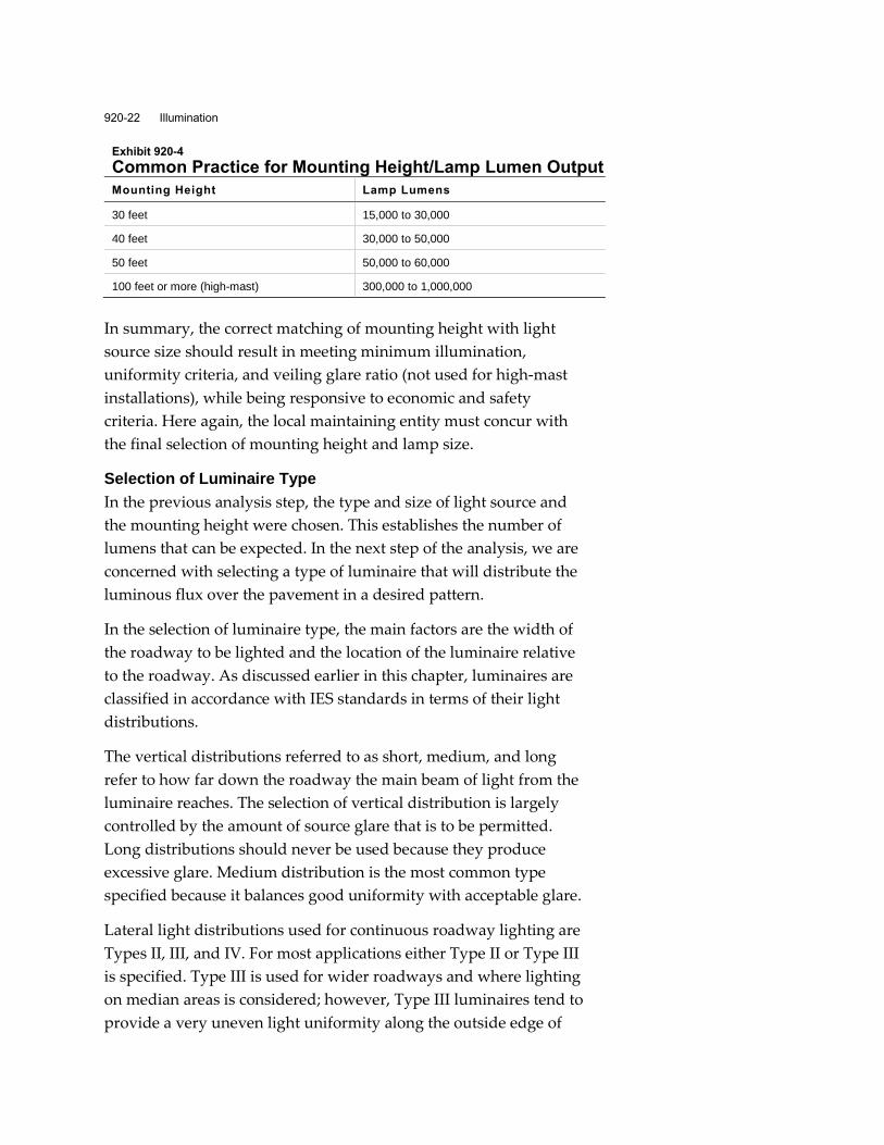
Exhibit 920-4 shows common practice for mounting height and
lumen combinations:
920-22 Illumination
Exhibit 920-4
Common Practice for Mounting Height/Lamp Lumen Output
Mounting Height Lamp Lumens
30 feet 15,000 to 30,000
40 feet 30,000 to 50,000
50 feet 50,000 to 60,000
100 feet or more (high-mast) 300,000 to 1,000,000
In summary, the correct matching of mounting height with light
source size should result in meeting minimum illumination,
uniformity criteria, and veiling glare ratio (not used for high-mast
installations), while being responsive to economic and safety
criteria. Here again, the local maintaining entity must concur with
the final selection of mounting height and lamp size.
Selection of Luminaire Type
In the previous analysis step, the type and size of light source and
the mounting height were chosen. This establishes the number of
lumens that can be expected. In the next step of the analysis, we are
concerned with selecting a type of luminaire that will distribute the
luminous flux over the pavement in a desired pattern.
In the selection of luminaire type, the main factors are the width of
the roadway to be lighted and the location of the luminaire relative
to the roadway. As discussed earlier in this chapter, luminaires are
classified in accordance with IES standards in terms of their light
distributions.
The vertical distributions referred to as short, medium, and long
refer to how far down the roadway the main beam of light from the
luminaire reaches. The selection of vertical distribution is largely
controlled by the amount of source glare that is to be permitted.
Long distributions should never be used because they produce
excessive glare. Medium distribution is the most common type
specified because it balances good uniformity with acceptable glare.
Lateral light distributions used for continuous roadway lighting are
Types II, III, and IV. For most applications either Type II or Type III
is specified. Type III is used for wider roadways and where lighting
on median areas is considered; however, Type III luminaires tend to
provide a very uneven light uniformity along the outside edge of

NMDOT Design Manual 920-23
the roadway. In some cases, Type II distributions may provide a
more uniform appearance when used with high mounting heights
(40 to 50 feet). Type II should be used on ramps and two-lane roads.
Unless otherwise specified, the light distribution for luminaires on
NMDOT projects shall be in accordance with the NMDOT Standard
Specifications for Highway and Bridge Construction. All new
luminaires specified for use on the New Mexico highway system
shall be full cutoff.
High-mast lighting systems provide the advantage of
“redundancy” due to the fact that all of the luminaires are aimed at
the same location, providing overlapping light patterns. If an
outage occurs in one luminaire, the illumination level will be
proportionally decreased, but will not result in a dark area. The
decision to use either a symmetric or asymmetric distribution
should be determined by the particular design (e.g., lighting a series
of rectangular shaped areas may be better with asymmetric
distribution).
In summary, the width of the area to be lighted, the configuration
of luminaires, and the mounting height all affect the type of light
distribution that will produce the best uniformity of lighting while
minimizing glare. Much of the lighting analysis involves examining
various combinations of these factors in an effort to identify the best
combination. The designer is cautioned to refer to the
manufacturers’ data to determine the availability of certain
lamp/distribution combinations for particular luminaires.
Luminaire Support Spacing and Location
Thus far in the analysis process, a lamp/luminaire combination has
been selected and a tentative mounting height has been chosen. The
next step is to select the lateral and longitudinal mounting
dimensions. The lateral dimension, or the distance from the
roadway edge to the luminaire, is mainly governed by the need to
place the luminaire over the roadway. Safety considerations and
right-of-way restrictions require the use of various length mastarms
in order to correctly locate the luminaire support while leaving the
luminaire at its desired position.

920-24 Illumination
With high-mast lighting, the location of the luminaire supports
within the lighted area relative to the nearby roadway is also
important. Good high-mast lighting design should begin with
focusing attention on critical areas where luminaire supports
should or should not be placed. Once this step has been completed,
other less-critical poles may be fitted in to complete the total design.
For a high-mast lighting layout, the designer should begin with a
plan view of the area to be lighted and should tentatively locate the
luminaire supports according to the following design
considerations:
Masts should be located so that the highest localized levels of
illumination fall in the traffic conflict areas (e.g., ramp
terminals), and located a sufficient distance from the roadway
to position the greatest uniformity of illumination on the
pavement surface.
Masts should be at least 50 feet from the edge of the travel lanes
or the clear zone distance, whichever is greater, unless the
supports are protected by a barrier system.
In designing a lighting system, it is important to maximize spacing
of luminaires consistent with good illumination design. From the
standpoint of economy and safety, the minimum number of
luminaires and luminaire supports should be used while satisfying
the illumination quantity and quality criteria.
Luminaire spacing should be based on analysis using software such
as AGi32. This software program will use photometric data for the
light source provided by lighting equipment manufacturers, which
will include the lamp lumen output (LL, the initial lumen output of
a lamp.)
As time passes, the efficiency of every luminaire is reduced. The
designer needs to estimate this reduction to properly estimate the
light available at the end of the maintenance life of the lamp. Lamp
lumen depreciation and luminaire dirt depreciation values must be
estimated and used in the software analysis. The overall adjustment
factor is called the maintenance factor (MF). This factor may range
from 0.50 to 0.90, with the typical range being from 0.65 to 0.75.
Default values are 0.70 for LED and 0.65 for HPS luminaires.

NMDOT Design Manual 920-25
The maintenance factor (MF = EF + LLD + LDD) is a combination of
factors used to denote the reduction of the illumination for a given
area after a period of time compared to the initial illumination on
the same area. It is based on the following:
Equipment factor (EF) - To compensate for the normal
production tolerances of commercially available luminaires, it is
common practice to estimate the equipment loss at five to
10 percent (i.e., EF = .95 to .90). This information should be
provided by the manufacturer.
Lamp lumen depreciation factor (LLD) - As the lamp
progresses through its service life, the lumen output of the lamp
decreases. This is an inherent characteristic of all lamps. The
initial lamp lumen value is factored by a lumen depreciation
factor to compensate for the anticipated lumen reduction. This
assures that a minimum level of illumination will be available at
the end of the assumed lamp life, even though lamp lumen
depreciation has occurred. This information should be provided
by the manufacturer.
Luminaire dirt depreciation factor (LDD) - Dirt on the exterior
and interior of the luminaire, and to some extent on the lamp,
reduces the amount of light reaching the roadway. Various
degrees of dirt accumulation may be anticipated, depending
upon the area in which the luminaire is located. Dust, industrial
plant emissions, and vehicle exhaust (especially from large
diesel trucks) are among the sources that contribute to the
accumulation of dirt on the luminaire. Higher mounting heights
tend to reduce vehicle-related dirt accumulations.
Checking for Design Adequacy
Lighting analysis software will provide the designer with metrics
for the proposed layout including average maintained illuminance
and minimum illuminance. From these, the uniformity ratio,
comparing the average illumination level to the minimum
illumination level, can be calculated. The lighting analysis software
will also provide the veiling luminance ratio. (Note that the veiling
luminance ratio cannot easily be calculated for high-mast lighting
and is therefore not required.) These metrics can then be compared
to the values in the AASHTO Roadway Lighting Design Guide. If

920-26 Illumination
the values are within the acceptable range for the particular area
and type of roadway, the illumination design may be acceptable.
Otherwise, the analysis should be repeated using other luminaire
and pole configurations.
The results of the lighting analysis shall be documented in a memo
for submittal to the NMDOT Traffic Design Section. NMDOT may
request that the calculations be accompanied by an iso-footcandle
diagram showing lighting levels at the quarter-lane lines, or
schematics of the project being lighted.
920.4.3 Lighting System Design
In general, lighting systems installed on state highways should
conform in equipment and design to the NMDOT Standard
Specifications for Highway and Bridge Construction, and the latest
NMDOT Standard Drawings. Specific criteria for the selection and
design of lighting equipment include the following:
Luminaires shall provide a light distribution in accordance with
American National Standards Institute (ANSI) and IESNA
photometric standards.
Luminaire supports shall be designed in accordance with
AASHTO “LRFD Specifications for Structural Supports for
Highway Signs, Luminaires, and Traffic Signals.”
Electrical distribution and service systems for lighting
installations shall conform to the requirements of the NEC.
920.4.3.1 Pole Placement Considerations
The placement of luminaire poles should allow sufficient
illumination of the traveled way and special roadside features
without reducing roadside safety. However, the placement will be
influenced by physical conditions, which include roadway
geometry, utility poles, spacing of access points, right-of-way
limitations, roadway bridge structures, and other overhead
structures (signs, overpasses). It is generally more economical to
use higher mounting heights with high lumen output luminaires
providing longer spacing intervals. This permits more design
flexibility in avoiding roadside obstacles, spanning problem areas,
and reducing the overall number of poles. The ultimate mounting is

NMDOT Design Manual 920-27
limited by the width of the roadway to be lighted, the range of the
luminaire distribution, the local ability to maintain, and possible
light trespass concerns.
In addition to the illumination patterns the following factors should
be considered for placing luminaire poles:
Access to luminaires for servicing
Vehicle-pole collision probabilities
System glare aspects
Visibility (day and night) of traffic control devices (signs,
signals)
Daytime aesthetic appearance
Overhead utilities and trees
Locations at intersections to allow for joint use with traffic
signals
Compatibility with special roadside features for pedestrian and
bicycle access, including compliance with ADA access
requirements
Roadside Safety
In addition to the considerations above, there should be adequate
right-of-way, driveway control, and utility clearance to allow for
the placement of a proposed lighting system in accordance with
roadside safety requirements. In some cases, additional
right-of-way, driveway control, and/or utility relocations may be
required before lighting can be installed.
The designer should take into account the following safety
considerations when determining the location of light poles:
Breakaway poles are preferred except in situations where a
falling pole could cause more damage than that caused by an
automobile striking a rigid pole. For example, non-breakaway
poles should be considered in an area where substantial
pedestrian traffic exists or is expected, or where overhead
electric lines are close.
Poles should be placed outside the roadside clear zone (refer to
the Roadside Design Guide). Poles placed within the clear zone

920-28 Illumination
shall be provided with a breakaway device or, if a non-
breakaway pole is used within the clear zone, it shall be
shielded by guardrail.
All breakaway devices shall comply with all applicable
AASHTO requirements for structural supports and may be one
of the several forms that have been approved for use as a
breakaway device (see NMDOT Standard Specifications for
Highway and Bridge Construction and latest Standard
Drawings for lighting).
All poles that require a breakaway device shall be served by
underground wiring.
Poles should desirably be located to provide adequate safety
clearance in the gore areas of the exit and entrance ramps.
Poles should desirably be placed on the inside of sharp curves
and loops. However, they shall have sufficient clearance to
avoid being struck by trucks if the radius is superelevated.
The hazards to be encountered while performing future
maintenance on the lighting equipment should be considered in
determining pole locations.
Poles should be placed to minimize interference with the
driver’s view of the roadway or any highway signs.
Poles should be placed behind flexible railings or rigid barriers
if they are present.
Poles that are shielded by a guardrail should be offset a distance
of at least four feet to allow the railing to deflect without hitting
the pole. If this clearance distance is not available, such as in
extreme side-slope conditions, or if the pole is located within
75 feet of the approach end of the flexible railing, a breakaway
device should be added.
Poles that are shielded by a rigid or non-yielding barrier type
will not require a breakaway device unless the pole is located
within 75 feet of the approach end of the barrier.
Poles may be located either on top of or behind retaining walls.
Poles mounted on top of retaining walls will require that special
consideration be given to the retaining wall design.

NMDOT Design Manual 920-29
Poles should not be installed within three feet of the face of the
barrier curb to the centerline of the pole.
Poles may be placed in median locations where median barriers
are used or where the median width is sufficient to provide
clear zone setback from both directions.
Poles with a breakaway device should have the top of the
footing constructed as close to ground level as possible to
ensure the proper action of the breakaway device and to
prevent damage to the foundation or the underside of an
impacting vehicle. In order for the breakaway device to perform
properly, it must be installed in accordance with the latest
AASHTO Breakaway Specifications, the manufacturer’s
recommendations, and the NMDOT Standard Drawings.
Poles, either with or without breakaway devices, should be
located in such a manner that they will not interfere with the
functional operation of any impact attenuator or other safety
breakaway device.
The construction of a special feature such as a curb, barrier, or
other obstacle primarily to protect a light pole will not be
allowed, unless approved by NMDOT prior to construction.
Unprotected high-mast towers shall be at least 50 feet from the
edge of the travel lanes or the clear zone distance, whichever is
greater.
Access for service vehicles shall be provided for high-mast
towers and service poles.
Overhead Structures
Short underpasses such as those encountered where a roadway
goes under a two- or four-lane roadway can generally be lighted
satisfactorily with properly positioned standard luminaires.
Exhibit 920-5 offers guidance on the placement of luminaires near
narrow bridges and overhead structures.
Luminaires on the lower roadway should be positioned so that
there are no large discontinuities in the pavement illumination on
either side of the overpass and the design illumination is
maintained. Care also must be taken to minimize glare on the
roadway going over the lighted roadway, from luminaires placed
for the lower roadway illumination. (Where an unlighted roadway

920-30 Illumination
crosses over a lighted roadway, the overpass for the unlighted
roadway should be lighted.) Longer underpasses, where such
overlapping of the illumination from the street luminaires cannot
be accomplished, may require the addition of underpass luminaires
mounted to the understructure.
Bridge Structures
For continuous lighting of a roadway, part of which is on a bridge
structure (overpass or drainage separation) that is longer than the
design luminaire spacing, one or more luminaire poles will be
required on the structure. Generally, the same luminaire spacing is
required on the structure as on the roadway on both sides;
however, the structure design itself will normally place physical
limitations on the exact location of the luminaires. Typically, the
luminaire poles will be rigidly mounted to the pier caps. The
spacing of lighting on bridge structures will then be required to
vary from the design, but desirably it will not exceed the design
spacing, ensuring the minimum design illumination and
uniformity. In extreme cases, where it is very difficult or costly to
obtain the minimum luminaire spacing, longer spacing may be
permitted; however, this spacing should not exceed 20 percent of
the standard spacing used off of the bridge. When the bridge
structure is within an interchange, especially a complex interchange
with numerous structures, the high-mast lighting option should be
considered to eliminate the need for lighting on structures.

NMDOT Design Manual 920-31
Exhibit 920-5
Illumination Shadow Lines

920-32 Illumination
The designer shall verify that
the standard foundation
drawings are appropriate for
the particular situation; i.e.,
the conditions are within the
design parameters shown in
the NMDOT Standard
Drawings. Where conditions
require a custom foundation
design it shall be submitted to
the State Bridge Engineer for
approval
920.4.3.2 Lighting Equipment
A variety of options are available to the designer in selecting
lighting equipment that will meet the desired design criteria. The
designer must ensure that the selected equipment meets NMDOT
Standard Specifications for Highway and Bridge Construction and
designs and is compatible with the local maintenance entities’
preferences. Specialized equipment and designs can significantly
increase the installation and maintenance costs, thereby reducing
the cost effectiveness of the lighting system. The designer is
encouraged to contact the Traffic Section for an approved products
list.
Light Poles (Standards)
Light standards are the most common supports used to provide
illumination for highway facilities. The NMDOT typically uses
30-foot, 40-foot, or 50-foot Type V light standards with a 10-foot
arm length (single or double arm) and slip bases. On state
highways, alternative light standards, including decorative poles,
may be considered if requested by the local public entity, provided
they agree to pay any additional costs associated with this change.
It should be noted that the NMDOT maintenance yards typically do
not stockpile decorative poles or poles other than the typical Type V
standard to use as a replacement in the event of a knockdown.
For high-mast installations, the NMDOT uses a Type VI standard
with a 75-, 100-, 120-, or 150-foot tapered steel tube pole.
Luminaires mounted on a high-mast pole will require a lowering
device for maintenance.
Light Pole Foundations
The designer shall verify that the standard foundation drawings for
the light poles are appropriate for the particular situation; i.e., the
conditions are within the design parameters shown in the NMDOT
Standard Drawings. Where conditions require a custom foundation
design it shall be submitted to the State Bridge Engineer for
approval.
NMDOT Design Manual 920-33
Luminaires
In recent years there has been a transition from HPS luminaires to
LED luminaires for highway lighting. NMDOT Traffic Section staff
will direct the designer on which LED luminaires may be used on a
project.
Electrical and Service Systems
The electrical distribution system encompasses the equipment that
performs the following functions:
Distributing electrical energy to individual luminaires.
Energizing and de-energizing the system or portions of the
system.
Transforming commercial power where necessary into a form
usable by the luminaire.
The location (and feasibility) of the electrical service connection
point with the local electrical utility system must be established
during preliminary design activities to:
Establish the feasibility of obtaining electrical energy for a
proposed lighting system or right-of-way easements that the
electrical utility may need for line extensions.
Establish any costs and/or fees for the electrical utility to
provide electrical energy at the project site and at the proper
secondary supply voltage.
Establish the exact point(s) the electrical service can be provided
within the project area right-of-way so the distribution system
can be properly designed and sized.
The electrical utility service feed may be underground or by
overhead lines that would require the installation of a service pole
and/or service riser. Between the electrical service point and the
luminaire electrical distribution system is a control center. This
includes the switching gear, photoelectric controls, and required
protection devices and terminals, normally enclosed in a ground-
mounted cabinet. The lighting control cabinet may or may not have
provision for metering, dependent on the agreement between the
local maintenance entity and the local utility, as to the means of rate
measurement. The electrical service(s) and lighting control cabinets

920-34 Illumination
should conform to the latest NMDOT Standard Drawing and be
sized in accordance with each specific project’s requirements.
The lighting secondary electrical distribution systems used on New
Mexico highways are multiple circuits, commonly a 240-volt,
two-wire (plus ground) single-phase system. In some cases, a
480-volt system may be used, but a 120-volt system should not be
used because of excessive voltage drops. Also, a three-phase system
may be used as a high-mast distribution system for some
applications. The exact voltage selected is typically what is
commonly used locally, and in all cases shall be concurred with by
the local maintenance entity and the utility provider. The
luminaires must be specified to operate at the selected secondary
distribution system voltage.
All secondary lighting distribution systems used on New Mexico
highways (except some privately owned lighting systems placed on
electrical utility poles) should be installed underground in a
conduit system. A pull box should be provided at each junction of
three or more conduits, and at access points in a buried conduit line
spaced no further than 300 feet apart. All material and installation
of the conduit, wiring, and protection devices should be as specified
in the NMDOT Standard Specifications for Highway and Bridge
Construction
Circuit Design
The electrical design of secondary lighting distribution systems
involves the selection and sizing of the conductors. Some
knowledge of electricity and power distribution is required of the
designer to make these determinations.
The required conductors are sized by determining the voltage drop
caused by the design electrical load. The voltage drop in any
electrical circuit is directly dependent upon the operating current - a
function of the lamp wattage and the operating voltage, and wire
resistance - a function of the length and size of the conductor. For
design purposes, the maximum allowable voltage drop for the most
distant luminaire in a circuit to the service point should not exceed
10 percent, assuming a magnetic-regulator (mag-reg) ballast is used.
NMDOT Design Manual 920-35
Voltage drop calculations shall be submitted to the NMDOT Traffic
Section for review and approval prior to the completion of the
design.
920.4.3.3 Plan Layout
The plan layout of the lighting system should be drawn at a scale of
1” = 100’. The layout should include areas showing the position of
the luminaires, the poles, and the electrical distribution/service
system. Match lines should be used with multiple sheets.
Features shown on the lighting plans should include:
Pavement outlines, existing and proposed, with lane widths and
curbs
Sidewalks, wheelchair ramps (existing and proposed),
crosswalks, and lane lines
Identification of all roads
Driveways and drainage structures
Utilities
Location of any railroad crossing
Arrows showing pavement lane use
North arrow
Location of any signal poles, controller, and conduit
Location of luminaires, poles, and number identification of each
Pull box locations
Electrical distribution
Title block stating location
Locations of signs
Existing lighting and removals
Barrier systems
Right-of-way limits
920.4.3.4 Work on Existing Illumination Systems
There are design considerations that need to be addressed when
performing even the most minimal work on an existing
illumination system. An existing electrical system is acceptable for
920-36 Illumination
use under the design requirements and NEC rules that were in
effect at the time of installation. When modifying an existing
electrical service or transformer, the designer is responsible for
bringing the whole system up to current NEC design standards.
Existing conductors and components that no longer meet current
NEC requirements are to be replaced and the whole circuit is to be
designed to current standards. This may mean replacing the whole
circuit back to the nearest circuit breaker.
Excess roadway lighting or roadway lighting not in use may be
removed when approved by the appropriate District Engineer or
Designee and the General Office Traffic Section. The requesting
public entity shall be responsible for the associated removal costs.
920.4.4 Agreements
Prior to completion of design and letting, the NMDOT will prepare
a lighting agreement or Joint Powers Agreement. In accordance
with NMDOT policy, all lighting on state roadways, including
installation projects partially or fully federal/state funded, is to be
maintained by the appropriate local municipality or county entity.
The agreement will stipulate that the local public entity will take
responsibility for all energy and maintenance costs for lighting. If
an agreement cannot be executed between the public entity and the
NMDOT, the NMDOT will not assume responsibility for the
lighting installation.
A permit shall be required from the NMDOT if a public entity or
private owner intends to install lighting on state highway
right-of-way. The costs of installation, maintenance, electrical
usage, and relocation shall be borne by the public entity and/or
private property owner, and it shall be so stipulated in the permit.
The lighting installation shall be subject to NMDOT review and
approval. The lighting installation may be performed by the public
entity, a contractor, or an electrical utility.
The NMDOT may assume responsibility for 100 percent of the
roadway light installation cost if the facility on the highway system
satisfies a warrant listed earlier in this chapter. NMDOT
participation in project construction cost shall be limited to the use
of NMDOT-approved standard equipment in accordance with

NMDOT Design Manual 920-37
NMDOT specifications and design procedures. The public entity
shall be responsible for any incremental cost difference due to
different design practices or the use of other than NMDOT standard
equipment. All equipment used on state facilities shall be an
approved product.
If the subject location does not satisfy any of the warrants listed
earlier in this chapter, the NMDOT may participate in funding for
the below-ground portion of the street lighting. The public entity
shall be responsible for the above-ground portion and related
energy and maintenance costs.
920.5 Documentation
The installation of roadway lighting on a NMDOT facility may
require the following documentation to be prepared and submitted
to the NMDOT Traffic Section:
Warrant study
Recommendation for installation from NMDOT Traffic Section
Letter of intent to maintain from local public entity
Light levels/uniformity analysis and an iso-footcandle diagram
Voltage drop calculations
State Bridge Engineer approval of custom-designed light pole
foundation (if applicable)
Lighting agreement
Permit for installation of lighting equipment in NMDOT
right-of-way
