9/24/09 rm1350 installation and operating instructions
TRANSCRIPT
825129202(French 825129252)©2006-2009 Dometic, LLCLaGrange, IN 46761
installation &
operating instructions
MO 0939
rM1350
USA Corporate Office CANADA Service Office 2320 Industrial Parkway Elkhart, IN 46516 Dometic, LLC Dometic, LLC 46 Zatonski, Unit 3 2320 Industrial Pkwy. Brantford, ON N3T 5L8 Elkhart, IN 46516 For Service Center Assistance CANADA Phone: 574-294-2511 Call: 800-544-4881 Phone: 519-720-9578
FOR YOUR SAFETYIf you smell gas:1. Open windows. 2. Don’t touch electrical switches. 3. Extinguish any open flame. 4. Immediately call your gas supplier.
POUR vOTRE SéCURITéSi vous sentez une odeur de gaz:1. Ouvrez les fenêtres.2. Ne touchez à aucun interrupteur.3. Éteignez toute flamme nue.4. Avertissez immédiatement votre
fournisseur de gaz.
FOR YOUR SAFETYDo not store or use gasoline or other flammable vapors and liquids in the vicinity of this or any other appliance.
POUR vOTRE SéCURITéNe pas entreposer ni utiliser de l’essence ni d’autres vapeurs ou liquides inflamma-bles à proximité de cet appareil ou de tout autre appareil.
Improper installation, adjustment, alteration, service or maintenance can cause injury or property damage. Refer to this manual. For assistance or additional information consult a qualified installer, service agency or the gas supplier.
Une installation, un réglage, une modifi-cation, une réparation ou un entretien non conforme aux normes peut entraîner des blessures ou des dommages matériels. Lisez attentivement le mode d’emploi fourni avec l’appareil. Pour obtenir de l’aide ou des renseignements supplémen-taires, consultez un installateur ou un service d’entretien qualifié ou le fournis-seur de gaz.
warning avertissement6! 6!
If the refrigerator stops cooling - or - if ammonia emanates from it, immediately turn the refrigerator off and contact a Service Center.
Si le réfrigérateur cesse de refroidir - ou - si de l’ammoniac s’en dégage, arrêtez immé-diatement le réfrigérateur et contactez un centre de réparation.
warning avertissement6! 6!

- 3 -
contents
introduction . . . . . . . . . . . . . . . . . . . . . . . . . . . . . . . . . . . . . . . . . . . . . . . . . . . . . . . . . . . . . . . . . . . . 4
installation instructionscertification and code requirements . . . . . . . . . . . . . . . . . . . . . . . . . . . . . . . . . . . . . . . . . . . . 4
ventilation requirements . . . . . . . . . . . . . . . . . . . . . . . . . . . . . . . . . . . . . . . . . . . . . . . . . . . . . . . . 5
installation procedure . . . . . . . . . . . . . . . . . . . . . . . . . . . . . . . . . . . . . . . . . . . . . . . . . . . . . . . . . . 6
connections . . . . . . . . . . . . . . . . . . . . . . . . . . . . . . . . . . . . . . . . . . . . . . . . . . . . . . . . . . . . . . . . . . . . . 8
mounting the door panels . . . . . . . . . . . . . . . . . . . . . . . . . . . . . . . . . . . . . . . . . . . . . . . . . . . . . . 10
operating instructionsrefrigerator overvieW . . . . . . . . . . . . . . . . . . . . . . . . . . . . . . . . . . . . . . . . . . . . . . . . . . . . . . . . . . 13
operating instructions . . . . . . . . . . . . . . . . . . . . . . . . . . . . . . . . . . . . . . . . . . . . . . . . . . . . . . . . . 18
storage compartments . . . . . . . . . . . . . . . . . . . . . . . . . . . . . . . . . . . . . . . . . . . . . . . . . . . . . . . . . 20
product care . . . . . . . . . . . . . . . . . . . . . . . . . . . . . . . . . . . . . . . . . . . . . . . . . . . . . . . . . . . . . . . . . . . 21
maintenance & service . . . . . . . . . . . . . . . . . . . . . . . . . . . . . . . . . . . . . . . . . . . . . . . . . . . . . . . . . . 22
refrigerator removal . . . . . . . . . . . . . . . . . . . . . . . . . . . . . . . . . . . . . . . . . . . . . . . . . . . . . . . . . . 25
troubleshooting . . . . . . . . . . . . . . . . . . . . . . . . . . . . . . . . . . . . . . . . . . . . . . . . . . . . . . . . . . . . . . . 25
diagnostic test . . . . . . . . . . . . . . . . . . . . . . . . . . . . . . . . . . . . . . . . . . . . . . . . . . . . . . . . . . . . . . . . 27
appendix a - spare parts . . . . . . . . . . . . . . . . . . . . . . . . . . . . . . . . . . . . . . . . . . . . . . . . . . . . . . . . . 28
appendix b - rearvieW equipment . . . . . . . . . . . . . . . . . . . . . . . . . . . . . . . . . . . . . . . . . . . . . . . . 29
appendix c - Wiring diagram . . . . . . . . . . . . . . . . . . . . . . . . . . . . . . . . . . . . . . . . . . . . . . . . . . . . . 31
appendix d - consumer support . . . . . . . . . . . . . . . . . . . . . . . . . . . . . . . . . . . . . . . . . . . . . . . . . 34
appendix e - dometic Warranty . . . . . . . . . . . . . . . . . . . . . . . . . . . . . . . . . . . . . . . . . . . . . . . . . . 35
appendix f - maintenance schedule . . . . . . . . . . . . . . . . . . . . . . . . . . . . . . . . . . . . . . . . . . . . . . . . . 36
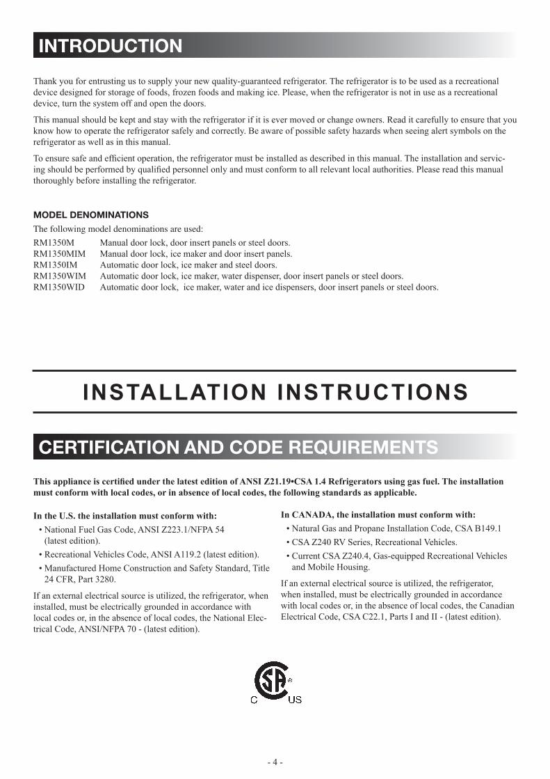
symbols
The following symbols are used throughout the manual:
Indicates a potentially hazardous situation, which, if not avoided, could result in death or serious injury.
Indicates a potentially hazardous situation, which, if not avoided, may result in minor or moderate injury. Used without the safety alert symbol indicates, a potentially hazardous situation which, if not avoided may result in property damage.
Information
Step-by-step instructions
CAUTION!
WARNING!
CAUTION
- 4 -
introduction
Thank you for entrusting us to supply your new quality-guaranteed refrigerator. The refrigerator is to be used as a recreational device designed for storage of foods, frozen foods and making ice. Please, when the refrigerator is not in use as a recreational device, turn the system off and open the doors.
This manual should be kept and stay with the refrigerator if it is ever moved or change owners. Read it carefully to ensure that you know how to operate the refrigerator safely and correctly. Be aware of possible safety hazards when seeing alert symbols on the refrigerator as well as in this manual.
To ensure safe and efficient operation, the refrigerator must be installed as described in this manual. The installation and servic-ing should be performed by qualified personnel only and must conform to all relevant local authorities. Please read this manual thoroughly before installing the refrigerator.
model denominationsThe following model denominations are used:
RM1350M Manual door lock, door insert panels or steel doors.RM1350MIM Manual door lock, ice maker and door insert panels.RM1350IM Automatic door lock, ice maker and steel doors.RM1350WIM Automatic door lock, ice maker, water dispenser, door insert panels or steel doors.RM1350WID Automatic door lock, ice maker, water and ice dispensers, door insert panels or steel doors.
certification and code requirements
This appliance is certified under the latest edition of ANSI Z21.19•CSA 1.4 Refrigerators using gas fuel. The installation must conform with local codes, or in absence of local codes, the following standards as applicable.
In the U.S. the installation must conform with:National Fuel Gas Code, ANSI Z223.1/NFPA 54 • (latest edition).Recreational Vehicles Code, ANSI A119.2 (latest edition).• Manufactured Home Construction and Safety Standard, Title • 24 CFR, Part 3280.
If an external electrical source is utilized, the refrigerator, when installed, must be electrically grounded in accordance with local codes or, in the absence of local codes, the National Elec-trical Code, ANSI/NFPA 70 - (latest edition).
In CANADA, the installation must conform with:Natural Gas and Propane Installation Code, CSA B149.1• CSA Z240 RV Series, Recreational Vehicles.• Current CSA Z240.4, Gas-equipped Recreational Vehicles • and Mobile Housing.
If an external electrical source is utilized, the refrigerator, when installed, must be electrically grounded in accordance with local codes or, in the absence of local codes, the Canadian Electrical Code, CSA C22.1, Parts I and II - (latest edition).
INSTALLATION INSTRUCTIONS
- 5 -
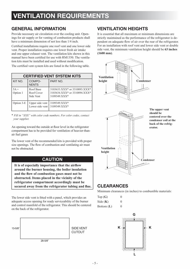
clearances Minimum clearances (in inches) to combustible materials:
Top (G) 0Side (K) 0Bottom (L) 0
G
KK
L
ventilation requirements
The lower vent of the recommended kits is provided with proper size openings. The flow of combustion and ventilating air must not be obstructed. The lower side vent is fitted with a panel, which provides an adequate access opening for ready serviceability of the burner and control manifold of the refrigerator. This should be centered on the back of the refrigerator.
general informationProvide necessary air circulation over the cooling unit. Open-ings for air supply or for venting of combustion products shall have a minimum dimension of not less than 1/4 inch. Certified installations require one roof vent and one lower side vent. Proper installation requires one lower fresh air intake and one upper exhaust vent. The ventilation kits shown in this manual have been certified for use with RM1350. The ventila-tion kits must be installed and used without modification.The certified vent system kits are listed in the following table.
Side vent cutout
LOWER VENT CUTOUT
13-5/8”
28-5/8”
certified vent system kitsKit no. compo-
nentS part no.
5A = Option 1
Roof BaseRoof CoverSide Vent
3103633.XXX* or 3310893.XXX*3103634.XXX* or 3310894.XXX*3109349.XXX*
Option 3-E Upper side ventLower side vent
3109349.XXX*3109349.XXX*
* Fill in “XXX” with color code numbers. For color codes, contact your supplier.
An opening toward the outside at floor level in the refrigerator compartment has to be provided for ventilation of heavier-than-air fuel gases
CAUTIONIt is of especially importance that the airflow around the burner housing, the boiler insulation and the flow of combustion gases must not be obstructed. Items placed in the vicinity of the refrigerator compartment accordingly must be secured away from the refrigerator tubing and flue.
ventilation heightsIt is essential that all maximum or minimum dimensions are strictly maintained as the performance of the refrigerator is de-pendent on adequate flow of air over the rear of the refrigerator. For an installation with roof vent and lower side vent or double side vent, the minimum ventilation height should be 63 inches (1600 mm).
CondenserVentilation height
The upper vent should be centered over the condenser coil at the back of the refrig-erator.
Condenser
Ventilation height

- 6 -
securing the refrigeratorIt is important to follow the sequence in securing refrigerator in enclosure since failure in doing so can cause leakage be-tween the frame and cabinet. Any space between the counter, storage area or ceiling and top of the refrigerator greater than 1-1/2 inches should be blocked. The heat produced at the rear of the refrigerator will become trapped in this space, making the top of the refrigerator hot and reduce the efficiency of the refrigerator. After the refrigerator is put in place (ensuring a combustion seal at the front frame), the refrigerator is to be secured in the enclosure with six screws (not included).
installation procedure
A wood strip must be in place across the upper opening • of the enclosure. The top frame of the refrigerator will be anchored to the wood strip with screws.
installing the refrigerator The refrigerator must be installed in a substantial enclosure • and must be level. Do not install the appliance directly on carpeting. Carpet-• ing must be removed or protected by a metal or wood panel beneath the appliance, which extends at least full width and depth of the appliance.All areas within the recess in which the refrigerator is • installed must be sealed. Make sure that there is a complete seal between the front frame of the refrigerator and the top, sides and bottom of the enclosure. A length of sealing strip is applied to the rear surface of the front frame for this purpose. The sealing strip should provide a complete isola-tion of the appliance’s combustion system from the vehicle interior.
Be careful not to damage the sealing strip when the refrigerator is put in place!
Wood strip
ventilation requirements
OVeRAll DImeNSIONS
Height (A) mm 1632
inches 64-17/64
Width (B) mm 855
inches 33-11/16
Depth (C) mm722 (steel doors)
750 (door insert panels)
inches28 1/16 (steel doors)
29 1/2 (door insert panels)
ReCeSS DImeNSIONS
Height (H) mm 1605
inches 63-3/16
Width (W) mm 832
inches 32-3/4
Depth (D) mm 662
inches 26-1/16
overall and recess dimensions
view from above
DW
C
B
Side view
D
H A
- 7 -
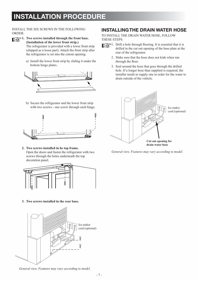
INSTALL THE SIX SCREWS IN THE FOLLOWING ORDER:
Two screws installed through the front base. 1. (Installation of the lower front strip.) The refrigerator is provided with a lower front strip (shipped as a loose part). Attach the front strip after the refrigerator is set into the cutout opening.
Install the lower front strip by sliding it under the a) bottom hinge plates.
Secure the refrigerator and the lower front strip b) with two screws - one screw through each hinge.
Two screws installed in he top frame. 2. Open the doors and fasten the refrigerator with two screws through the holes underneath the top decoration panel.
Two screws installed in the rear base.3.
installing the drain water hoseTO INSTALL THE DRAIN WATER HOSE, FOLLOW THESE STEPS:
Drill a hole through flooring. It is essential that it is 1. drilled in the cut out opening of the base plate at the rear of the refrigerator. Make sure that the hose does not kink when run 2. through the floor. Seal around the hose that goes through the drilled 3. hole. If a longer hose than supplied is required, the installer needs to supply one in order for the water to drain outside of the vehicle.
Cut out opening for drain water hose
Ice maker cord (optional)
Ice maker cord (optional)
General view. Features may vary according to model.
General view. Features may vary according to model.
installation procedure

- 8 -
alternator (d+) connection D+ connection is only valid for models with the automatic door locking system. The refrigerator requires the connection of a signal wire from the alternator (D+) in order to maintain the automatic door travel latch and the temporary gas lockout function. The gas operation will automatically be locked out for a period of 15 minutes when the engine is switched off. This will prevent gas operation e.g. when stop-ping at a refueling station.
Connect the vehicles alternator (D+) to the D+ on the terminal block.
connections
electrical connection120 v ac connectionThe refrigerator is equipped with a three-prong (grounding) plug for your protection against shock hazards and should be plugged directly into a properly grounded three prong recep-tacle. Do not cut or remove the grounding prong from this plug! The free length of the cord is 3 feet. It is recommended that the receptacle is located to the right side of the refrigerator (viewed from the rear).The receptacle should be 3” (from the bottom of the plastic receptacle) above the refrigerator mounting floor. This allows easy access through the vent door. The cord should be routed to avoid direct contact with components that could damage the cord insulation.
12v dc The refrigerator requires a continuous 12V DC supply to maintain operation. The DC supply connection is made to the positive (+) and negative (-) terminals of the terminal block on the back of the refrigerator. Correct polarity must be observed when connecting to the DC supply. Do not use the chassis or vehicle frame as one of the conductors. Connect two wires at the refrigerator and route to the DC supply. It is important that the wires to the 12V DC terminal is of proper wire size. The following table displays the recommended size and length of the conductor wires.
maximum total conductor wire length
Wire length AWG
17 ft (5 m) 14
27 ft (8 m) 12
Example: If the distance between the refrigerator and the 12V DC supply is 17 ft, the total wire length is 34 ft and a wire size of 14 AWG should be used.
Battery
B+
Alternator signal wire to the refrigerator D+
ALTERNATOR
Ignition switch
Charge light
D+ (Alternator signal wire) Valid for refrigerator models with the automatic door lock-ing system.
3”
General view. Features may vary according to model.

- 9 -
gas connectionHook up to the gas supply line is accomplished at the manual gas valve, which is furnished with a 3/8” SAE (UNF 5/8” -18) male flare connection. All completed connections should be checked for leaks with a commercial non corrosive bubble solution.
Always use a back up wrench when loosening and tightening connections.
The gas supply system must incorporate a pressure regulator to maintain a supply pressure of not more than 11 inches water column. When testing the gas supply system at test pressures:
> 1/2 psi• - the refrigerator and its individual shutoff valve must be disconnected from the gas supply piping system. ≤ 1/2 psi • - the appliance must be isolated from the gas supply piping system by closing its individual manual shut-off valve.
For detailed instructions on the installation and con-nection to the gas supply, please contact your dealer or distributor.
testing lp gas safety shut offThe gas safety shut off must be tested after the refrigerator is connected to LP gas supply.
TO TEST THE GAS SAFETy SHUT OFF, FOLLOW THESE STEPS:
Turn on the refrigerator and switch to GAS mode. 1. Check that the GAS indicator dot is illuminated and the gas flame is lit.Close the manual gas shut off valve at the back of 2. the refrigerator.Wait for approx. 45 seconds. The message 3. “LP” is displayed (flashing).Remove the protection cover. 4. Open the manual gas shut off valve. (Do not change 5. any button positions on the control panel.)Apply a non corrosive commercial bubble solution 6. to the burner jet orifice. No bubbles should appear at the opening of the burner jet orifice. The presence of bubbles indicates a defective gas safety shut off, and service is required.
connections
If no bubbles were present at the burner jet orifice, 7. rinse it with fresh water. Be careful not to damage the burner jet orifice. Put back the cover.8. Switch the refrigerator OFF and back ON again. 9. Normal operation of the burner should return. Allow the burner to operate for a minimum of 5 10. minutes.
water supply connection rm1350im, rm1350mim, rm1350wim & rm1350widThe water supply system must have a minimum pressure of 15 pounds per square inch gauge (psig). A 1/4” diameter water line to the water valve should be used at the rear of the refrig-erator. The water line must have a manual shutoff valve placed where it is easily accessible.
wARNINgeXPlOSION HAZARD. Never use an open flame to check for gas leaks. Failure to heed this warn-ing could cause an explosion resulting in death or severe personal injury.
6!
- 10 -
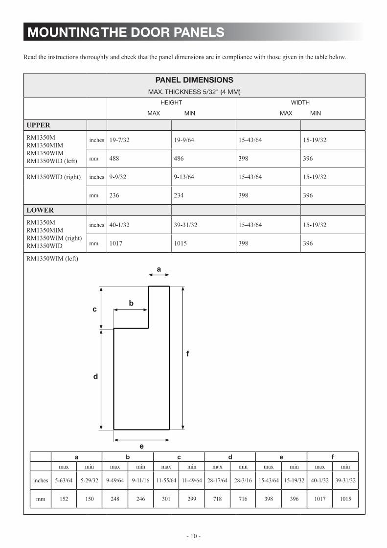
mounting the door panels
panel dimensions max. thicKneSS 5/32" (4 mm)
height
max min
width
max min
UPPeR
RM1350MRM1350MIMRM1350WIM RM1350WID (left)
inches 19-7/32 19-9/64 15-43/64 15-19/32
mm 488 486 398 396
RM1350WID (right) inches 9-9/32 9-13/64 15-43/64 15-19/32
mm 236 234 398 396
lOWeR
RM1350MRM1350MIMRM1350WIM (right)RM1350WID
inches 40-1/32 39-31/32 15-43/64 15-19/32
mm 1017 1015 398 396
RM1350WIM (left)
Read the instructions thoroughly and check that the panel dimensions are in compliance with those given in the table below.
f
c
d
b
a
ea b c d e f
max min max min max min max min max min max min
inches 5-63/64 5-29/32 9-49/64 9-11/16 11-55/64 11-49/64 28-17/64 28-3/16 15-43/64 15-19/32 40-1/32 39-31/32
mm 152 150 248 246 301 299 718 716 398 396 1017 1015

- 11 -
mounting the door panels
TO MOUNT THE DOOR PANEL, FOLLOW THESE STEPS:
Open the door.1. Remove the screw (A). Slide off the handle (B).* 2.
Slide off the decoration strip. 3.
Insert the door panel’s edges into the grooves of the 4. door frame. Push the panel sideways until the edge of the panel is fitted into the opposite side groove.
Put back the decoration strip. Slide (A) or 5. snap (B) into place.
Slide the handle into place (A) and attach with 6. the screw (B).
AB
BA
A
B
* For RM1350WID it is not necessary to remove the right freezer door handle in order to mount the door panel.

- 12 -
refrigerator overview
models with the manual door locking system
General view of the appliance. Model shown is equipped with ice maker. The number of shelves and door compartments may vary according to the user’s requirements.
Door compartment
Shelf
Draining pipe
Finned plate
Drip protection
Crispers
Control panel LED display
Ice boxAiring position device (detachable)
OPERATINg INSTRUCTIONS
- 13 -
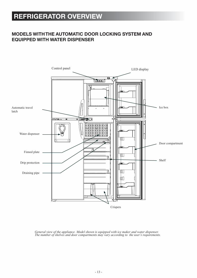
refrigerator overview
General view of the appliance. Model shown is equipped with ice maker and water dispenser. The number of shelves and door compartments may vary according to the user’s requirements.
Door compartment
Shelf
Draining pipe
Finned plate
Drip protection
Crispers
Automatic travel latch
Water dispenser
Control panel LED display
Ice box
models with the automatic door locking system and equipped with water dispenser
- 14 -
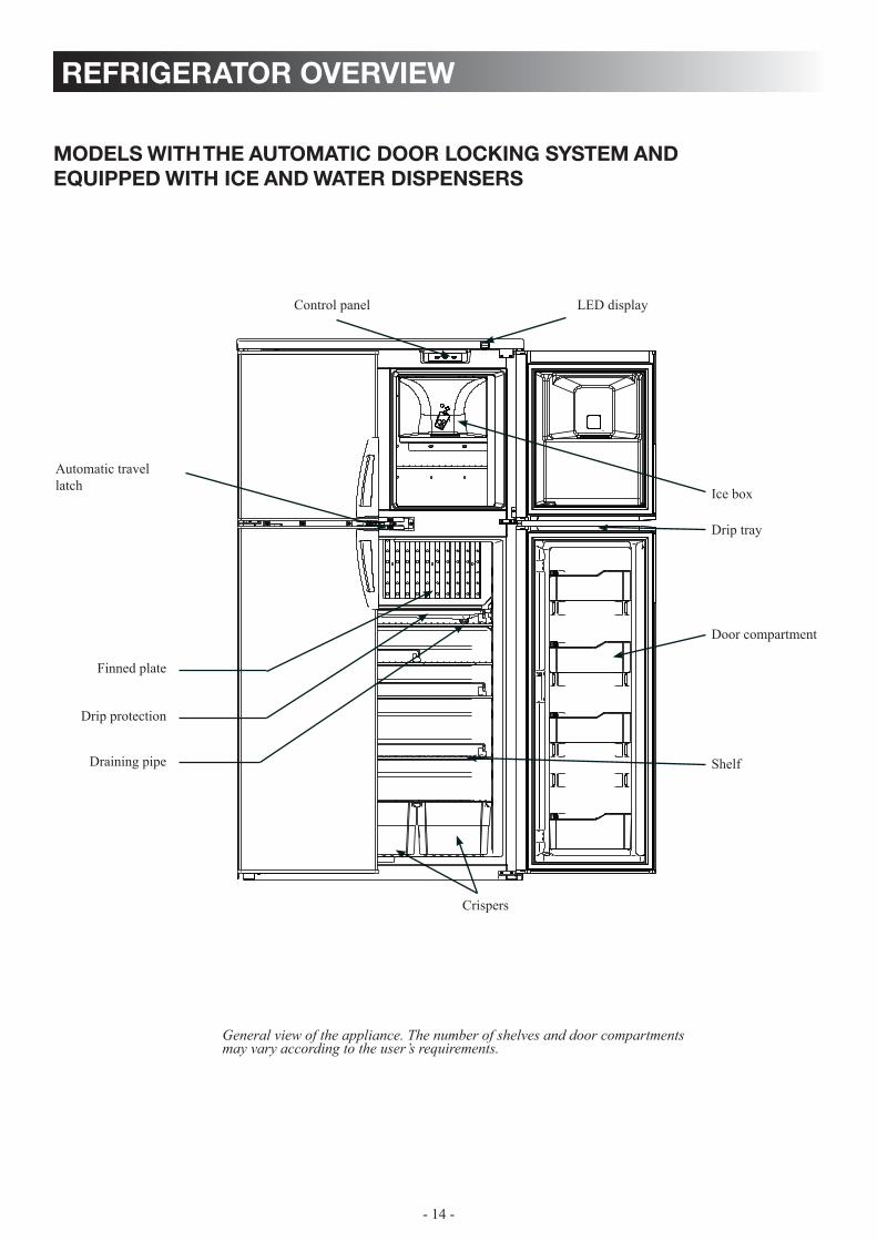
refrigerator overview
General view of the appliance. The number of shelves and door compartments may vary according to the user’s requirements.
Door compartment
Shelf
Crispers
Automatic travel latch
Control panel LED display
Ice box
Drip tray
Draining pipe
Finned plate
Drip protection
models with the automatic door locking system and equipped with ice and water dispensers

- 15 -
refrigerator overview
control panel
ON/OFF1. button (main power) Press the button to turn the refrigerator ON or OFF.
AUTO/GAS2. mode selector button Press the button to turn the AUTO mode ON or OFF.
TemP. SeT button3. The thermostat has 5 settings where 1 indicates the warm-est and 5 the coldest temperature setting. Press the button repeatedly until the desired setting, e.g. 3, is shown in the LED display. This value is shown for about 5 seconds and then the temperature is displayed once again.
1 2 3
led panel indications status information
Display is on Refrigerator on
Display is off Refrigerator off
The AUTO indication dot is lit.
AUTO mode and AC operation
The AUTO and LP indication dots are lit.
AUTO mode and GAS operation
The AUTO indication dot is lit. LP indication dot flashes slowly.
Temporary gas lockout function. Only in AUTO mode. It pre-vents gas operation when stopping at a refueling station.
The LP indication dot is lit.
Manual GAS operation mode.
Digits e.g. Fresh food temperature.
Thermostat range setting indication (1 - 5). Temporary during setting. The thermostat settings are stored automatically after 5 sec. of inactivity.
Message indications:
“60” is displayed.
Temperature is above measurement range
“LP” is flashing (The message alternates between “LP” and the temperature.)
Gas operation lock out. (Check gas.)
4
- 16 -
refrigerator overview
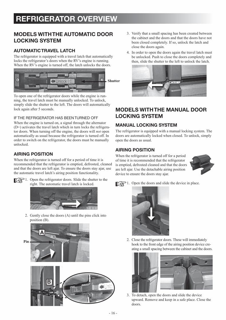
Verify that a small spacing has been created between 3. the cabinet and the doors and that the doors have not been closed completely. If so, unlock the latch and close the doors again.In order to open the doors again the travel latch must 4. be unlocked. Push to close the doors completely and then, slide the shutter to the left to unlock the latch.
models with the manual door locking system
manual locking systemThe refrigerator is equipped with a manual locking system. The doors are automatically locked when closed. To unlock, simply open the doors as usual.
airing positionWhen the refrigerator is turned off for a period of time it is recommended that the refrigerator is emptied, defrosted cleaned and that the doors are left ajar. Use the detachable airing position device to ensure the doors stay ajar.
Open the doors and slide the device in place. 1.
Close the refrigerator doors. These will immediately 2. hook to the front edge of the airing position device cre-ating a small spacing between the cabinet and the doors.
To detach, open the doors and slide the device 3. upward. Remove and keep in a safe place. Close the doors.
models with the automatic door locking system
automatic travel latchThe refrigerator is equipped with a travel latch that automatically locks the refrigerator’s doors when the RV’s engine is running. When the RV’s engine is turned off, the latch unlocks the doors.
To open one of the refrigerator doors while the engine is run-ning, the travel latch must be manually unlocked. To unlock, simply slide the shutter to the left. The doors will automatically lock again after 5 seconds.
if the refrigerator haS been turned offWhen the engine is turned on, a signal through the alternator (D+) activates the travel latch which in turn locks the refrigera-tor doors. When turning off the engine, the doors will not open automatically as usual because the refrigerator is turned off. In order to switch on the refrigerator, the doors must be manually unlocked.
airing positionWhen the refrigerator is turned off for a period of time it is recommended that the refrigerator is emptied, defrosted, cleaned and that the doors are left ajar. To ensure the doors stay ajar, use the automatic travel latch’s airing position functionality.
Open the refrigerator doors. Slide the shutter to the 1. right. The automatic travel latch is locked.
Gently close the doors (A) until the pins click into 2. position (B).
Shutter
Pin
A
B
- 17 -
refrigerator overview
purging air from the linesIf the refrigerator has not been used for a long time - or -the LP tanks have just been refilled, air may be trapped in the supply lines. To purge the air from the lines, turn the refrigera-tor off and on by pressing the ON/OFF button. If the flame is not lit within 45 seconds, turn the refrigerator off and back on again. This procedure can be repeated 3 to 4 times. If repeated attempts fail to start the LP gas operation, check to make sure that the LP gas supply tanks are not empty and that all manual shutoff valves in the lines are open.
automatic cooling unit cycling system and low ambient controlThe refrigerator has been design with an automatic cooling unit cycling system that helps reduce frost build up in the fresh food compartment. The first automatic frost reduction cooling unit cycle begins 60 hours after turning “on” the refrigerator (for best operational results the refrigerator should be turned on anytime between 4 and 10 PM), and will last for approximately 120 minutes. Thereafter, the cycle will automatically repeat every 48 hours as long as the refrigerator continues to run. The automatic Low Ambient Control (LAC) ensures trouble-free operation in low ambient temperatures (e.g below 50° F).
auto mode / gas modeThe refrigerator is equipped with a control system where the user can choose to turn the AUTO mode on or off.
auto mode is turned on The system is fully automatic which means that it selects the most suitable energy source available, either 120V AC or LP gas operation.
temporary gaS locKout
The gas operation will automatically be locked out for a period of 15 minutes when the engine is switched off. This will pre-vent gas operation e.g. when stopping at a refueling station.
auto mode is turned off (gas mode)The system operates on LP gas only. The control system activates the ignition system and makes one attempt to light the burner. Note that the temporary gas lockout feature does not work when the AUTO mode is turned off! Consequently, when parking close to a gasoline pump all LP gas appliances vented to the outside of the vehicle must be turned off. Other-wise gasoline fumes from gasoline pumps might enter LP gas appliance and these can then ignite from the burner flame and cause a fire or an explosion.
absorption cooling systemIn an absorption refrigerator system, ammonia is liquefied in the finned condenser coil at the top rear of the refrigerator. The liq-uid ammonia then flows into the evaporator (inside the freezer section) and is exposed to a circulating flow of hydrogen gas, which causes the ammonia to evaporate, creating a cold condi-tion in the freezer.
When starting this refrigerator for the very first time, the cooling cycle may require up to four hours of running time before the cooling unit is fully operational.
The tubing in the evaporator section is specifically sloped to provide a continuous movement of liquid ammonia, flowing downward by gravity through this section. Sodium chromate is used for corrosion protection (less than 2 weight % of the coolant).
leveling the refrigeratorLeveling is one of the requirements for proper operation with absorption refrigerators. To ensure proper leveling the vehicle needs to be leveled only so it is comfortable to live in (no notice-able sloping of floor or walls). Any time the vehicle is parked for several hours with the refrig-erator operating, the vehicle should be leveled to prevent this loss of cooling.
If the refrigerator is operated when it is not level and the vehicle is not moving, liquid ammonia will accumulate in sections of the evaporator tubing. This will slow the circulation of hydrogen and ammonia gas, or in severe cases, completely block it, resulting in a loss of cooling.When the vehicle is moving, the leveling is not critical, as the rolling and pitching movement of the vehicle will pass to either side of level, keeping the liquid ammonia from accumulating in the evaporator tubing.
when the refrigerator is not in useAny absorption refrigerator that is to be taken out of service for an extended period of time should be turned off.
wARNINgFIRe OR eXPlOSION HAZARD. When refueling or parked near gasoline pumps, when the AUTO mode is turned off, shut off all lP gas appliances. Failure to heed this warning could cause a fire or explosion resulting in death or severe personal injury.
6!
CAUTIONDo not park your RV on a slope for a longer period of time. Absorption refrigerators use a gravity-flow system. Being on an angle of more than a couple of degrees for ex-tended periods of time stops the refrigeration and might cause damage to the cooling unit.
CAUTIONIt is important that you do not leave the refrigerator to run idle and/or unattended for days or weeks.

- 18 -
operating instructions
turning on the refrigerator
Check that all the manual gas valves are in the ON 1. position.Make sure that a continuous 12V DC supply is 2. available for the electronic control to function. Press the ON/OFF button. 3. Select operation mode:4.
AUTO mode (AC and GAS) -Press the AUTO/GAS mode selector button (if not already on).GAS mode (gas operation only) -Press the AUTO/GAS mode selector button to turn off the AUTO mode (if not already off).
adjusting the thermostat The adjustable thermostat ranges from 1 - 5 (5 = coldest temperature setting).
After the initial start-up, adjust the thermostat by pressing the TEMP. SET button repeatedly until the desired setting is displayed.
The thermostat controls both the gas and electric operation. Thus, it is not necessary to reset each time a different energy source is employed.
operating the ice makerrm1350im, rm1350mim, rm1350wim & rm1350wid Before the ice maker can operate, make sure that:
The refrigerator is connected to 120 V AC . • The water valve supplying the refrigerator is turned on.• The ice level bail arm is in its fully down position. •
When the ice maker thermostat senses the preset temperature for the ejection of the ice cubes, the fingers will start to rotate, dumping any ice cubes and filling the mold with water. When the storage container is full, the bail arm will come in contact with the ice cubes. The bail arm cannot return to the full down position and the ice production is stopped until the bin is emptied, or ice cubes are removed.
To prevent water from splashing out of the mold assembly when your recreational vehicle is moving, raise the bail arm to the full “UP/OFF” position about 1-1/2 hours before departing. This will allow the water in the mold to freeze.
water supplyThe water supply system must have a minimum pressure of 15 pounds per square inch gauge (psig). A 1/4” diameter water line to the water valve should be used at the rear of the refrig-erator. The water line must have a manual shutoff valve placed where it is easily accessible.The maximum water level is represented by a thin line. It is es-sential that the water level does not exceed this line!
If necessary, change the water flow by adjusting the water supply. For instructions, see ADjUSTING THE SIZE OF CUBES.
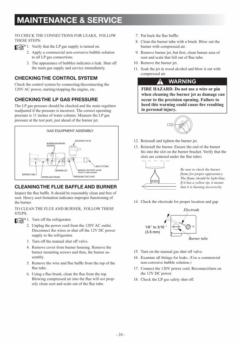
gaS equipment aSSembly
BURNER TUBE . SPARK ELECTRODE
BURNER JET
BURNER MOUNTINGSCREWS
PRESSURE TEST PORT
MANUAL SHUTOFF VALVE Shown in open position
INLET FITTING
SOLENOID VALVE
wARNINgFIRe HAZARD. Before lighting the gas burner, after that the RV has not been used for some time, please check that the gas path between the burner jet and the burner tube has not been obstructed. Failure to heed this warning could cause a fire re-sulting in personal injury.
6!
Maximum water level
Ice levelbail arm
Downposition

- 19 -
operating instructions
dispenser(s)rm1350widIf new installation or used for the first time after the RV has been winterized/put into storage, the water tank, located inside the refrigerator, must be filled with water. To fill the tank with water, follow these steps:
Insert a glass and press the right lever for 1. approx. 20 seconds. Pull glass away.2. Repeat steps 1 and 2 until water begins dispensing.3.
water dispenser (rm1350wim & rm1350wid)
TO DISPENSE WATER, FOLLOW THESE STEPS: Verify that the water valve supplying the refrigerator 1. is turned on. Insert a glass in the dispensing cavity and press the 2. lever. This will activate a switch which turns on an electric water valve at the back of the refrig-erator. Water will flow through a separate tube and out of the dispenser. To stop dispensing, pull glass away from the lever 3. before the glass is full.
If new installation, or used infrequently, dispense numerous glasses of water before use. To keep the water fresh, it is recommended to use the dispenser every day.
ice dispenser (rm1350wid)
In order to provide a smooth and consistent flow rate of ice and to avoid ice spillage, please make sure to adjust the size of the ice cubes as described in ADjUSTING THE SIZE OF CUBES.
TO DISPENSE ICE, FOLLOW THESE STEPS: Insert a glass in the dispensing cavity and press the 1. left lever. The ice maker has previously produced ice that are 2. stored in a large bin. When the lever is pressed, a switch is activated. It turns on a motor which rotates the auger. When the auger rotates, it pushes ice out of the bin, through a chute right into the glass. To stop dispensing, pull glass away from dispensing 3. arm before the glass is full. Allow ice chute to clear before removing glass.
adjusting the size of cubesIf the ice maker was cleaned and drained, no ice cubes will be dumped into the bin during the first cycle.
The first few cycles may have small cubes due to air trapped in the water lines. The first container of ice cubes should be dumped if the water system has been winterized or not used for several weeks. Once the ice maker has run through several cycles and if cubes are to small or sticking together, adjustment is necessary on the amount of water entering the mold.
TO ADjUST THE SIZE OF CUBES, FOLLOW THESE STEPS:Remove the protective cover from the ice maker 1. mechanism. Using a flat-head screwdriver, place the tip of the screwdriver in the slot. Twist the screw-driver blade gently to loosen the cover.
Locate the adjusting screw under the protective 2. cover. Turn the screw counterclockwise to increase the size of cubes.
Turn the screw clockwise to decrease the cube size 3. or if the mold is overfilling, and the cubes are stuck together.
To prevent overfilling, do not turn the adjustment screw more than one revolution at a time. Allow the ice maker to cycle several times before another adjustment is made. Be sure to replace the protective cover on the cycle after the adjustments are complete.
Cover
Adjusting screw
rm1350wim rm1350wid

- 20 -
turning off the refrigerator you can turn off your refrigerator by pressing the main power ON/OFF button found on the control panel to the off position. This will shut off all power to the refrigerator, including DC power to the refrigerator. If the refrigerator will not be in operation for a period of weeks or put into winter storage, it should be emptied, defrosted, cleaned and the doors left ajar. The ice trays should also be dried and kept outside the cabinet.
operating instructions
storage compartments
refrigerator volume Total refrigerator volume: 12.3 cu.ft
food storage compartmentCool the refrigerator before placing any food inside. • The food storage compartment is completely closed and • unventilated, which is necessary to maintain the required low temperature for food storage. Consequently, foods having a strong odor or those that absorb odors easily should be covered. Vegetables, salads etc. should be covered to retain their crisp-• ness. The coldest positions in the refrigerator are under the • cooling fins and at the bottom of the refrigerator. The warmer areas are on the upper door shelves. This should be consid-ered when placing different types of food in the refrigerator. Arrange all food in the unit to allow for free air circulation. • Do not overpack because a stuffed refrigerator must work harder and will have higher cabinet temperatures. Never put hot food or drinks into the refrigerator - cool • them first.Do not leave the unit’s door open any longer than necessary. • This will reduce frost formation and increase the efficiency of the refrigerator.
frozen food storage compartmentThis compartment is not designed for deep or quick freezingof food. To prevent food from drying out, keep it in covereddishes, containers, plastic bags or wrapped in aluminumfoil.
Quick frozen soft fruits and ice cream should be placed in the • coldest part of the compartment, which is at the bottom of the aluminum liner. Frozen vegetables, may be stored in any part of the compart-• ment.
locking the shelves in upright position It is possible to arrange the shelves in many ways to fit your needs. To gain more space, a shelf can be removed and locked into an upright position at the rear of the refrigerator compart-ment. Remove the shelf locks as described on the following page, tilt the shelf (A) and secure with the shelf locks (B).
GUARDS IN UPRIGHT POSITION
wARNINgeXPlOSION HAZARD. Never store explosive substances in the refrigerator, such as cigarette lighter fuel, gasoline, ether or the like. Failure to heed this warning could cause an explosion result-ing in death or severe personal injury.
6!
SHelF lOCk
A B
If your RV is being put into winter storage, it is recommended to either put your RV batteries on a battery charger or turn off the vehicle’s main 12V switch. This will prevent the RV battery from discharging. (The refrigerator’s control system still con-sumes a few milliamps even if it is turned off.)
Meat or fish, whether raw or prepared, can be stored in the • frozen food storage compartment provided they are pre-cooled first in the refrigerator. They can be stored about three times longer in the frozen food compartment as compared to the fresh food compartment. To prevent frost buildup, which can reduce the efficiency, • wipe excess moisture off items being placed in the compart-ment.
shelvesusing the shelf guardsTo prevent food product containers from shifting, two sliding retainer bars are mounted on the shelves. These can be em-ployed to separate the shelf into smaller sections which will hold the contents in place. Slide the shelf guards snugly against food item(s). The “front to back” shelf guard must be in upright position.
- 21 -
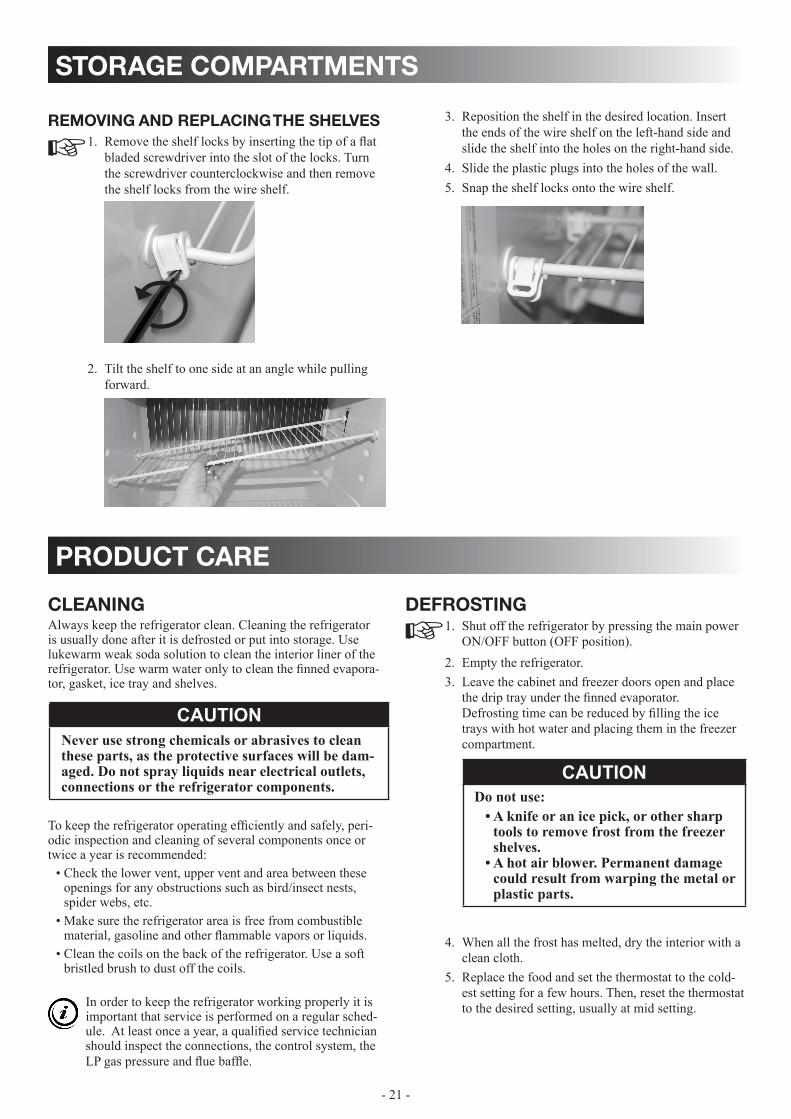
removing and replacing the shelvesRemove the shelf locks by inserting the tip of a flat 1. bladed screwdriver into the slot of the locks. Turn the screwdriver counterclockwise and then remove the shelf locks from the wire shelf.
Tilt the shelf to one side at an angle while pulling 2. forward.
product care
storage compartments
cleaningAlways keep the refrigerator clean. Cleaning the refrigerator is usually done after it is defrosted or put into storage. Use lukewarm weak soda solution to clean the interior liner of the refrigerator. Use warm water only to clean the finned evapora-tor, gasket, ice tray and shelves.
To keep the refrigerator operating efficiently and safely, peri-odic inspection and cleaning of several components once or twice a year is recommended:
Check the lower vent, upper vent and area between these • openings for any obstructions such as bird/insect nests, spider webs, etc. Make sure the refrigerator area is free from combustible • material, gasoline and other flammable vapors or liquids.Clean the coils on the back of the refrigerator. Use a soft • bristled brush to dust off the coils.
In order to keep the refrigerator working properly it is important that service is performed on a regular sched-ule. At least once a year, a qualified service technician should inspect the connections, the control system, the LP gas pressure and flue baffle.
defrostingShut off the refrigerator by pressing the main power 1. ON/OFF button (OFF position). Empty the refrigerator.2. Leave the cabinet and freezer doors open and place 3. the drip tray under the finned evaporator. Defrosting time can be reduced by filling the ice trays with hot water and placing them in the freezer compartment.
When all the frost has melted, dry the interior with a 4. clean cloth. Replace the food and set the thermostat to the cold-5. est setting for a few hours. Then, reset the thermostat to the desired setting, usually at mid setting.
CAUTIONNever use strong chemicals or abrasives to clean these parts, as the protective surfaces will be dam-aged. Do not spray liquids near electrical outlets, connections or the refrigerator components.
CAUTIONDo not use:
A knife or an ice pick, or other sharp • tools to remove frost from the freezer shelves. A hot air blower. Permanent damage • could result from warping the metal or plastic parts.
Reposition the shelf in the desired location. Insert 3. the ends of the wire shelf on the left-hand side and slide the shelf into the holes on the right-hand side. Slide the plastic plugs into the holes of the wall. 4. Snap the shelf locks onto the wire shelf.5.

- 22 -
Turn the gear counter clockwise, when the hold 11. switch closes, the mold assembly will continue to operate through the harvest cycle. During the water fill sequence of the harvest cycle the compressed air will blow out the water trapped in the solenoid valve.
maintenance & service
storage procedure/winterizing the refrigerator
rm1350im, rm1350mim, rm1350wim & rm1350widThe refrigerator is equipped with a heater tape wrapped around the water solenoid valve and outlet water tube. During cold weather operation below 32 °F/0 °C the automatic temperature switch will turn the heater tape on automatically. If the RV is in storage and the refrigerator or the DC power is turned OFF there will be no 12V DC present to operate the heat tape; therefore, it will be necessary to drain and dry the ice maker and the water dispenser (if applicable). This will prevent water from freezing in the solenoid valve or becoming stale and producing bad tasting ice. If the ambient temperature is expected to fall below 32 °F/0 °C, the ice maker and water dispenser (if applicable)must be drained to prevent component damage and leaks. For instructions, see the following sections DRAINING THE ICE MAkER and DRAINING THE WATER DISPENSER.
CAUTIONIf your refrigerator stops cooling, immediately turn the refrigerator off and see a Dometic dealer.
draining the ice makerDraining of the ice maker must be performed by qualified service personnel only. Water, compressed air and AC power are required.
Before starting the draining procedure, make sure the RV is level!
TO DRAIN THE ICE MAkER, FOLLOW THESE STEPS:Shut off water supply valve1. Place a shallow pan under water solenoid valve.2. Remove inlet fitting to ice maker water solenoid 3. valve.
WATeR SOleNOID VAlVe - Rm1350Im
Plastic nut
Metal tube
1/4” water line to ice maker
Water inlet hose
Inlet fitting for water supply line
WATeR SOleNOID VAlVe - Rm1350WIm & Rm1350WID
Outlet connection tubing:• Ice: 1/4” plastic hose• Water: 5/16” plastic hose
Inlet fitting for water supply line
Plastic nut:• Ice: 7/16” - 20 UNF• Water: 1/2” - 20 UNF
Water inlet hose
Ice Water
Metal tube
Drain water from the supply line. 4. Remove the plastic nut and water line from outlet 5. side of the water solenoid valve. Drain water from the line. 6. Connect compressed air onto the inlet fitting of the 7. water solenoid valve.Apply AC power to the solenoid valve by forc-8. ing the ice maker mold assembly through several harvest cycles. Remove the plastic cover from the mold assembly. 9. The bail arm must be in the down (“ON”) position. Start the harvest cycle with a flat blade screw driver 10. inserted into the center of the small gear.
- 23 -
periodic maintenance checking the connectionsLP gas is a flammable gas which has the potential to create a hazard. Do not smoke or create sparks when working on or near the LP gas system.
wARNINgeXPlOSION HAZARD. Never use an open flame to check for gas leaks. Failure to heed this warn-ing could cause an explosion resulting in death or severe personal injury.
6!
electric equipmentreplacing the heaterThe heat necessary for the operation of an absorption cooling unit is supplied by an electric heater mounted in a pocket of the boiler system. The refrigerator is equipped with a series con-nected twin heater.TO REPLACE THE HEATERS, FOLLOW THESE STEPS:
Turn off the refrigerator. Unplug the power cord and 1. disconnect the 12V DC power.Open the power module cover.2. Disconnect the heater leads.3. With a pair of pliers, unfold the lug holding the lid of 4. the boiler casing and then, open the lid. Remove some insulation wool for the heater to be 5. accessible.Turn and lift the heaters out of the pocket.6. Fit the new heaters into the pocket.7. Connect the leads and close the power module cover.8. Put back the insulation wool.9. Close the lid of the boiler. 10.
replacing the fuses The refrigerator is equipped with the following 3 fuses:
5 A fuse for 12V DC.• 5 A fuse for the AC heaters. • 3 A in-line fuse for the fan and heat tape and for • RM1350IM, RM1350MIM, RM1350WIM & RM1350WID for the ice maker, water and ice dispensers.
TO REPLACE A FUSE, FOLLOW THESE STEPS: Turn off the refrigerator and unplug the power cord.1. Open the power module cover.2. Snap the fuse out of the fuse holder.3. Fit the new fuse in to the fuse holder.4. Close the power module cover.5.
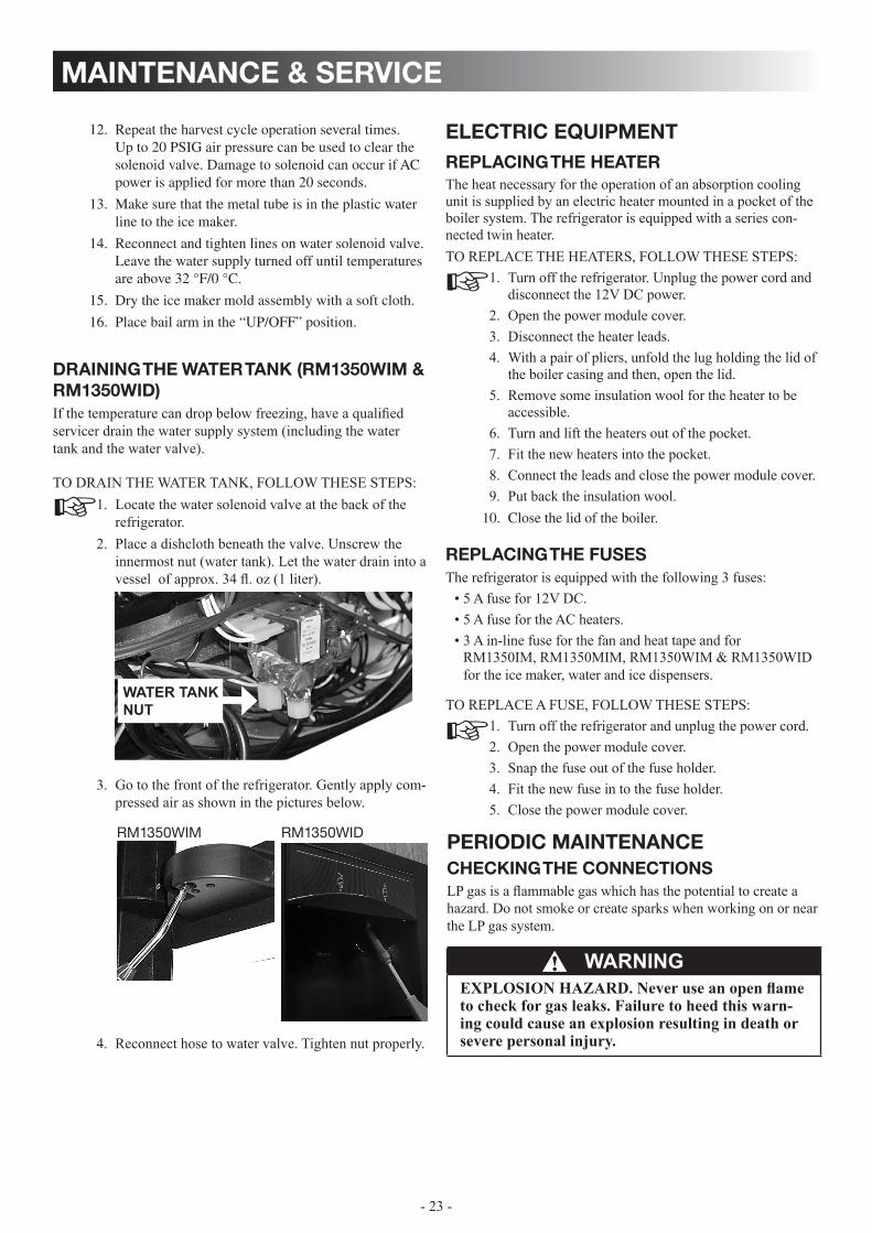
draining the water tank (rm1350wim & rm1350wid) If the temperature can drop below freezing, have a qualified servicer drain the water supply system (including the water tank and the water valve).
TO DRAIN THE WATER TANk, FOLLOW THESE STEPS:Locate the water solenoid valve at the back of the 1. refrigerator. Place a dishcloth beneath the valve. Unscrew the 2. innermost nut (water tank). Let the water drain into a vessel of approx. 34 fl. oz (1 liter).
Go to the front of the refrigerator. Gently apply com-3. pressed air as shown in the pictures below.
Reconnect hose to water valve. Tighten nut properly.4.
rm1350wim rm1350wid
wATER TANk NUT
maintenance & service
Repeat the harvest cycle operation several times. 12. Up to 20 PSIG air pressure can be used to clear the solenoid valve. Damage to solenoid can occur if AC power is applied for more than 20 seconds.
Make sure that the metal tube is in the plastic water 13. line to the ice maker.
Reconnect and tighten lines on water solenoid valve. 14. Leave the water supply turned off until temperatures are above 32 °F/0 °C.
Dry the ice maker mold assembly with a soft cloth.15.
Place bail arm in the “UP/OFF” position.16.
- 24 -
Reinstall and tighten the burner jet. 12.
Reinstall the burner. Ensure the end of the burner 13. fits into the slot on the burner bracket. Verify that the slots are centered under the flue tube).
Check the electrode for proper location and gap. 14.
Turn on the manual gas shut off valve. 15.
Examine all fittings for leaks. (Use a commercial 16. non-corrosive bubble solution.)
Connect the 120V power cord. Reconnect/turn on 17. the 12V DC power.
Check the LP gas safety shut off. 18.
Put back the flue baffle.7. Clean the burner tube with a brush. Blow out the 8. burner with compressed air. Remove burner jet, but first, clean burner area of 9. soot and scale that fell out of flue tube. Remove the burner jet. 10.
Soak the jet in wood alcohol and blow it out with 11. compressed air.
TO CHECk THE CONNECTIONS FOR LEAkS, FOLLOW THESE STEPS:
Verify that the LP gas supply is turned on.1. Apply a commercial non-corrosive bubble solution 2. to all LP gas connections. The appearance of bubbles indicates a leak. Shut off 3. the main gas supply and service immediately.
checking the control systemCheck the control system by connecting/disconnecting the 120V AC power, starting/stopping the engine, etc.
gaS equipment aSSembly
BURNER TUBE . SPARK ELECTRODE
BURNER JET
BURNER MOUNTINGSCREWS
PRESSURE TEST PORT
MANUAL SHUTOFF VALVE Shown in open position
INLET FITTING
SOLENOID VALVE
wARNINgFIRe HAZARD. Do not use a wire or pin when cleaning the burner jet as damage can occur to the precision opening. Failure to heed this warning could cause fire resulting in personal injury.
6!
Be sure to check the burner flame for proper appearance. The flame should be light blue. If it has a yellow tip, it means that it is burning incorrectly.
Electrode
Burner tube
1/8 ” to 3/16 ”(3-5 mm)
maintenance & service
checking the lp gas pressureThe LP gas pressure should be checked and the main regulator readjusted if the pressure is incorrect. The correct operating pressure is 11 inches of water column. Measure the LP gas pressure at the test port, just ahead of the burner jet.
cleaning the flue baffle and burnerInspect the flue baffle. It should be reasonably clean and free of soot. Heavy soot formation indicates improper functioning of the burner. TO CLEAN THE FLUE AND BURNER, FOLLOW THESE STEPS:
Turn off the refrigerator. 1. Unplug the power cord from the 120V AC outlet. 2. Disconnect the wires or shut off the 12V DC power supply to the refrigerator.Turn off the manual shut off valve.3. Remove cover from burner housing. Remove the 4. burner mounting screws and then, the burner as-sembly.Remove the wire and flue baffle from the top of the 5. flue tube. Using a flue brush, clean the flue from the top. 6. Blowing compressed air into the flue will not prop-erly clean soot and scale out of the flue tube.
- 25 -
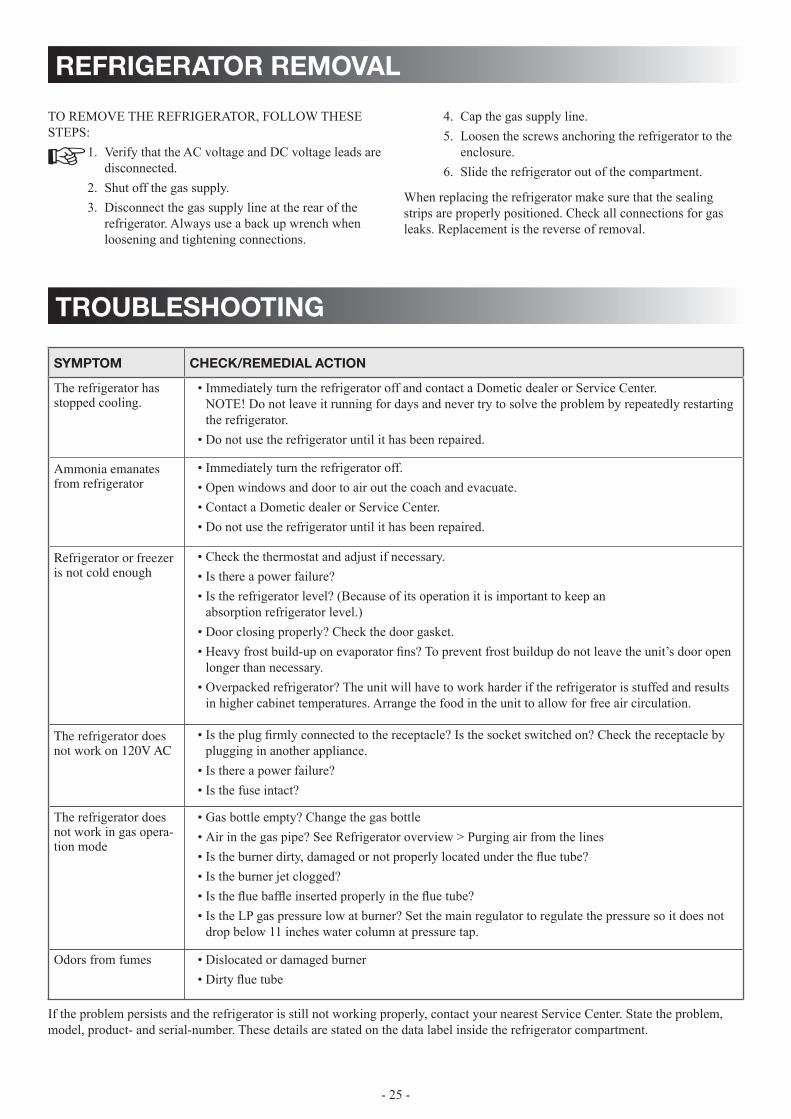
troubleshooting
symptom check/remedial action
The refrigerator has stopped cooling.
Immediately turn the refrigerator off and contact a Dometic dealer or Service Center. • NOTE! Do not leave it running for days and never try to solve the problem by repeatedly restarting the refrigerator.Do not use the refrigerator until it has been repaired.•
Ammonia emanates from refrigerator
Immediately turn the refrigerator off. • Open windows and door to air out the coach and evacuate.• Contact a Dometic dealer or Service Center. • Do not use the refrigerator until it has been repaired.•
Refrigerator or freezer is not cold enough
Check the thermostat and adjust if necessary. • Is there a power failure? • Is the refrigerator level? (Because of its operation it is important to keep an • absorption refrigerator level.)Door closing properly? Check the door gasket. • Heavy frost build-up on evaporator fins? To prevent frost buildup do not leave the unit’s door open • longer than necessary. Overpacked refrigerator? The unit will have to work harder if the refrigerator is stuffed and results • in higher cabinet temperatures. Arrange the food in the unit to allow for free air circulation.
The refrigerator does not work on 120V AC
Is the plug firmly connected to the receptacle? Is the socket switched on? Check the receptacle by • plugging in another appliance. Is there a power failure? • Is the fuse intact? •
The refrigerator does not work in gas opera-tion mode
Gas bottle empty? Change the gas bottle• Air in the gas pipe? See Refrigerator overview > Purging air from the lines• Is the burner dirty, damaged or not properly located under the flue tube?• Is the burner jet clogged?• Is the flue baffle inserted properly in the flue tube?• Is the LP gas pressure low at burner? Set the main regulator to regulate the pressure so it does not • drop below 11 inches water column at pressure tap.
Odors from fumes Dislocated or damaged burner • Dirty flue tube •
If the problem persists and the refrigerator is still not working properly, contact your nearest Service Center. State the problem, model, product- and serial-number. These details are stated on the data label inside the refrigerator compartment.
refrigerator removal
Cap the gas supply line.4. Loosen the screws anchoring the refrigerator to the 5. enclosure. Slide the refrigerator out of the compartment.6.
When replacing the refrigerator make sure that the sealing strips are properly positioned. Check all connections for gas leaks. Replacement is the reverse of removal.
TO REMOVE THE REFRIGERATOR, FOLLOW THESE STEPS:
Verify that the AC voltage and DC voltage leads are 1. disconnected. Shut off the gas supply. 2. Disconnect the gas supply line at the rear of the 3. refrigerator. Always use a back up wrench when loosening and tightening connections.
- 26 -
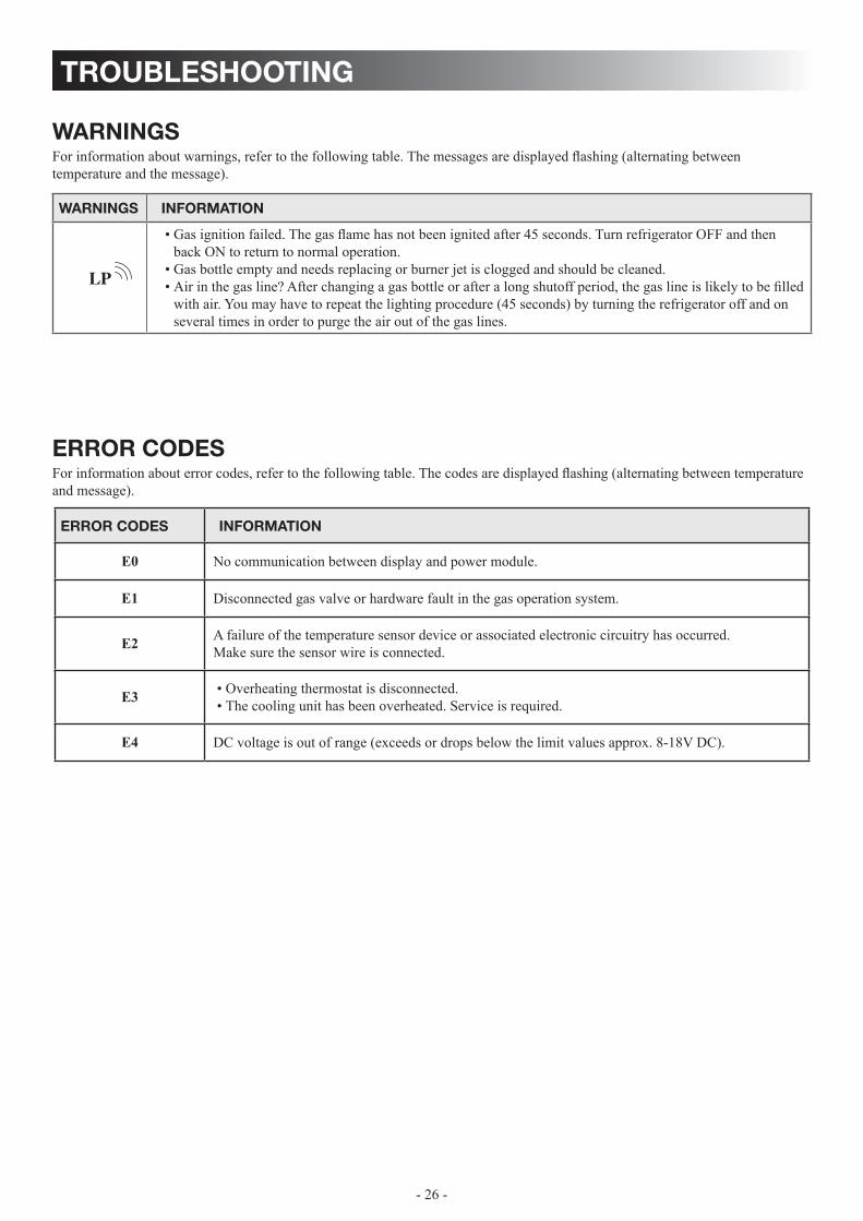
troubleshooting
error codesFor information about error codes, refer to the following table. The codes are displayed flashing (alternating between temperature and message).
error codes information
e0 No communication between display and power module.
e1 Disconnected gas valve or hardware fault in the gas operation system.
e2 A failure of the temperature sensor device or associated electronic circuitry has occurred. Make sure the sensor wire is connected.
E3 Overheating thermostat is disconnected. • The cooling unit has been overheated. Service is required.•
e4 DC voltage is out of range (exceeds or drops below the limit values approx. 8-18V DC).
warningsFor information about warnings, refer to the following table. The messages are displayed flashing (alternating between temperature and the message).
warnings information
LP
Gas ignition failed. The gas flame has not been ignited after 45 seconds. Turn refrigerator OFF and then • back ON to return to normal operation.Gas bottle empty and needs replacing or burner jet is clogged and should be cleaned.• Air in the gas line? After changing a gas bottle or after a long shutoff period, the gas line is likely to be filled • with air. you may have to repeat the lighting procedure (45 seconds) by turning the refrigerator off and on several times in order to purge the air out of the gas lines.
- 27 -
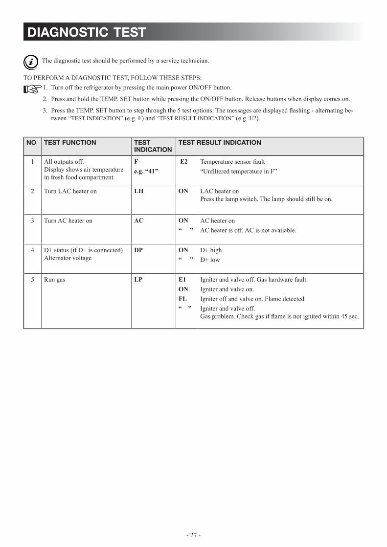
diagnostic test
TO PERFORM A DIAGNOSTIC TEST, FOLLOW THESE STEPS:Turn off the refrigerator by pressing the main power ON/OFF button.1.
Press and hold the TEMP. SET button while pressing the ON/OFF button. Release buttons when display comes on.2.
Press the TEMP. SET button to step through the 5 test options. The messages are displayed flashing - alternating be-3. tween “TEST INDICATION” (e.g. F) and “TEST RESULT INDICATION” (e.g. E2).
no test function test indication
test result indication
1 All outputs off. Display shows air temperature in fresh food compartment
Fe.g. “41”
e2 Temperature sensor fault“Unfiltered temperature in F”
2 Turn LAC heater on LH ON LAC heater on Press the lamp switch. The lamp should still be on.
3 Turn AC heater on AC ON“ ”
AC heater onAC heater is off. AC is not available.
4 D+ status (if D+ is connected)Alternator voltage
DP ON“ ”
D+ high D+ low
5 Run gas LP e1 ON Fl “ ”
Igniter and valve off. Gas hardware fault.Igniter and valve on.Igniter off and valve on. Flame detectedIgniter and valve off. Gas problem. Check gas if flame is not ignited within 45 sec.
The diagnostic test should be performed by a service technician.
- 28 -
appendix a - spare parts
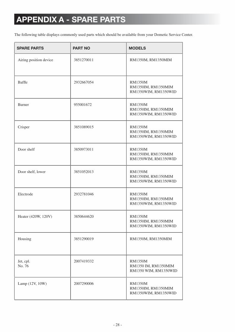
The following table displays commonly used parts which should be available from your Dometic Service Center.
spare parts part no models
Airing position device 3851270011 RM1350M, RM1350MIM
Baffle 2932667054 RM1350MRM1350IM, RM1350MIMRM1350WIM, RM1350WID
Burner 955001672 RM1350MRM1350IM, RM1350MIMRM1350WIM, RM1350WID
Crisper 3851089015 RM1350MRM1350IM, RM1350MIMRM1350WIM, RM1350WID
Door shelf 3850973011 RM1350MRM1350IM, RM1350MIMRM1350WIM, RM1350WID
Door shelf, lower 3851052013 RM1350MRM1350IM, RM1350MIMRM1350WIM, RM1350WID
Electrode 2932781046 RM1350MRM1350IM, RM1350MIMRM1350WIM, RM1350WID
Heater (420W, 120V) 3850644620 RM1350MRM1350IM, RM1350MIMRM1350WIM, RM1350WID
Housing 3851290019 RM1350M, RM1350MIM
Jet, cpl. No. 76
2007419332 RM1350MRM1350 IM, RM1350MIMRM1350 WIM, RM1350WID
Lamp (12V, 10W) 2007290006 RM1350MRM1350IM, RM1350MIMRM1350WIM, RM1350WID
- 29 -
appendix b - rearview equipment
385 13 31−01
HVT
J2 J3 J1 F4 (5A)
F3 (5A) SWITCHED 12V
LAMP TEST LINEAC HTR LINE
AC HTR NEUT
NEUT
12V DCD
Power moduleThermostat
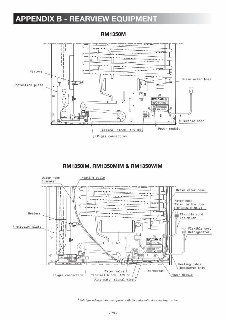
rm1350m
rm1350im, rm1350mim & rm1350wim
*Valid for refrigerators equipped with the automatic door locking system.
385 13 31−01
HVT
J2 J3 J1 F4 (5A)
F3 (5A) SWITCHED 12V
LAMP TEST LINEAC HTR LINE
AC HTR NEUT
NEUT
12V DCD
Power module
*

- 30 -
appendix b - rearview equipment
rm1350wid
Heaters
Drain water hose
Protection plate
Water hoseIcemaker
Heating cable
LP−gas connectionWater valve
Terminal block, 12V DC
Alternator signal wire
Thermostat
Flexible cordRefrigerator
Heating cable
Flexible cordIce dispenser
Water hoseWater dispenser door
385 13 31−01
5
HVT
J2 J3 J1 F4 (5A)
F3 (5A) SWITCHED 12V
LAMP TEST LINEAC HTR LINE
AC HTR NEUT
NEUT
5A
J5 J4 J3 J2
B E H I N D C O V E RC H E C K F U S E
J1
PART No. 385 13 78−01
W A R N I N G !DISCONNECT 120 V AC
BEFORE SERVICING
J6
12V DCD
Control unit
Power module
- 31 -
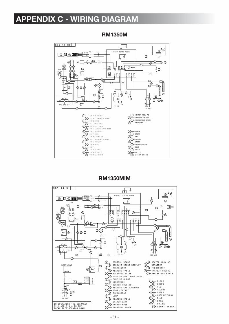
appendix c - wiring diagram
rm1350m
rm1350mim
+ L N
19
5
12V DC
CONTROL BOARDAB
CD
EF
HEATING CABLETHERMISTOR
KJ
LM
N LAMPTHERMOSTATDOOR CONTACT
BURNER HOUSING
G
CIRCUIT BOARD DISPLAY
SOLENOID VALVE
HEATING CABLE GIRDER
H ELECTRODE
O HEATING CABLEP SWITCH LAMP
3 8 5 1 4 9 1
RELAY
8 5
8 7
8 6
3 0
°
D+
S
UV
X
HEATER 120V AC
THERMOSTATCHASSIS GROUNDY
RETAINER
R THERMO FUSES TERMINAL BLOCK
98
W H I T EG R E YBLUE
REDBROWNBLACK1
23
45
67
GREENGREEN/YELLOW
YELLOW
10 L I G H T G R E E N
120 VAC
C
1
X
Y
1
4A
D
U
Z
P
N1
1 10
103 3
3
13
1
1
1
3
3
3
3
3
O
Y
Z PROTECTIVE EARTH
1
WHITEBLACKBROWNGREEN
L N
19
5
120 VAC
Z
9
ICEMAKER
I N OPERATION THE ICEMAKERWILL ADD 1.4 A TO THETOTAL REFRIGERATOR DRAW
1010
3 1
K
L
WATER VALVE
V
3
FAN
FAN
3
131
MC°
P1−1P1−2P1−3
B
BROWNBLACK
REDA
P2−1P2−29
9C
P2
G
F
P6
P7
P4
P3
P1
F 3
P5
J 2 J3 J1
7
1
H
R4
J
E
7
9
3
CIRCUIT BOARD POWER
1
9
3
FUSE 5A MINI AUTO FUSEFUSE 5A GLASS
+
L N
19
5
H
12V DC
P1−1P1−2P1−3
P2−1P2−29
9
B
BROWNBLACK
RED
P
CONTROL BOARDA
B
C
D
E
F
HEATING CABLE
THERMISTOR
K
J
L
M
N LAMP
THERMOSTAT
DOOR CONTACT
BURNER HOUSING
G
CIRCUIT BOARD DISPLAY
SOLENOID VALVE
HEATING CABLE GIRDER
H ELECTRODE
O
P
SWITCH LAMP
A
3 8 5 1 4 9 0
RELAY
8 5
8 7
8 6
3 0
FAN
D+
R
R
THERMO FUSE
TERMINAL BLOCK
9
8
W H I T E
G R E Y
BLUE
RED
BROWN
BLACK1
2
3
4
5
6
7
GREEN
GREEN/YELLOW
YELLOW
10 L I G H T G R E E N
120 VAC
U
1
°C M
4A
D
T
O
N
13
3
1
1 10
103 3
3
13
1
1
1
1
3 3
3
4
3
J
U
1
1010
K
3 1
L
C
V X
3
1
FAN
P2
P6
P7
P4
P3
P1
F 3
P5
J 2 J3 J1E
7
7
9
CIRCUIT BOARD POWER
3
1
93
FUSE 5A GLASS
FUSE 5A MINI AUTO FUSE
F
G
T
U
V
HEATER 120V AC
CHASSIS GROUND
PROTECTIVE EARTH
X RETAINER

- 32 -
appendix c - wiring diagram
rm1350im
rm1350wim
+
L N
19
5
12V DC
CONTROL BOARDAB
CD
EF
HEATING CABLETHERMISTOR
KJ
LM
N LAMPTHERMOSTATDOOR CONTACT
BURNER HOUSING
G
CIRCUIT BOARD DISPLAY
SOLENOID VALVE
HEATING CABLE GIRDER
H ELECTRODE
O HEATING CABLEP SWITCH LAMP
3 8 5 1 4 9 2
RELAY
8 5
8 7
8 6
3 0
FAN
°
D+
S
TU
VX
HEATER 120V ACDOOR IGNITION LOCK
THERMOSTATCHASSIS GROUNDY
RETAINER
R THERMO FUSES TERMINAL BLOCK
98
W H I T EG R E YBLUE
REDBROWNBLACK1
23
45
67
GREENGREEN/YELLOW
YELLOW
10 L I G H T G R E E N
120 VAC
C
1
X
Y
1
°C M
4A
D
1 2 3
T
U
Z
P
N
13
3
1
1 10
103 3
3
13
1
1
11
33
3
3
9
3
3
O
Y
Z PROTECTIVE EARTH
1
WHITEBLACKBROWNGREEN
L N
19
5
120 VAC
Z
9
ICEMAKER
I N OPERATION THE ICEMAKERWILL ADD 1.4 A TO THETOTAL REFRIGERATOR DRAW
1010
3 1
K
L
WATER VALVE
V
1
FAN
3
P1−1P1−2P1−3
B
BROWNBLACK
REDA
P2−1P2−29
9C
P2
G
F
P6
P7
P4
P3
P1
F 3
P5
J 2 J3 J1
7
H
R4
J
E
7
9
3
CIRCUIT BOARD POWER
1
3
1
FUSE 5A GLASSFUSE 5A MINI AUTO FUSE
9
+
L N
19
5
12V DC
CONTROL BOARDAB
CD
EF
HEATING CABLETHERMISTOR
FUSE 5A MINI AUTO FUSE
KJ
FUSE 5A GLASS
LM
N LAMPTHERMOSTATDOOR CONTACT
RETAINER
G
CIRCUIT BOARD DISPLAY
SOLENOID VALVE
HEATING CABLE GIRDER
H ELECTRODE
O HEATING CABLEP SWITCH LAMP
3 8 5 1 4 9 3
RELAY
8 5
8 7
8 6
3 0
°
D+
S
WHITEBLACKBROWNGREEN
TU
VX
HEATER 120V ACDOOR IGNITION LOCK
THERMOSTATCHASSIS GROUNDY
WATER DISPENSER
R THERMO FUSES TERMINAL BLOCK
98
W H I T EG R E YBLUE
REDBROWNBLACK1
23
45
67
GREENGREEN/YELLOW
YELLOW
10 L I G H T G R E E N
WATER VALVE W112VDC
W2120VAC
93
120 VAC
L N
19
5
120 VAC
Z
1 2 3
V
C
1
X
Y
1
°C M
4A
D
1 2 3
T
U
Z
P
N
13
3
1
1 10
103 3
3
13
1
1
11
33
33 1
3
9
3
3
O
9
ICEMAKER
Y
Z PROTECTIVE EARTH
1
IN OPERATION THE ICEMAKERWILL ADD 1.4 A TO THETOTAL REFRIGERATOR DRAW
1010
K
L
3 1
J
FAN
13
FAN
1
33
P1−1P1−2P1−3
B
BROWNBLACK
REDA
P2−1P2−29
9C
P2
G
F
P6
P7
P4
P3
P1
F 3
P5
J 2 J3 J1
CIRCUIT BOARD POWER
7
H
R4
J
E
7
9
3
11
9
3
- 33 -
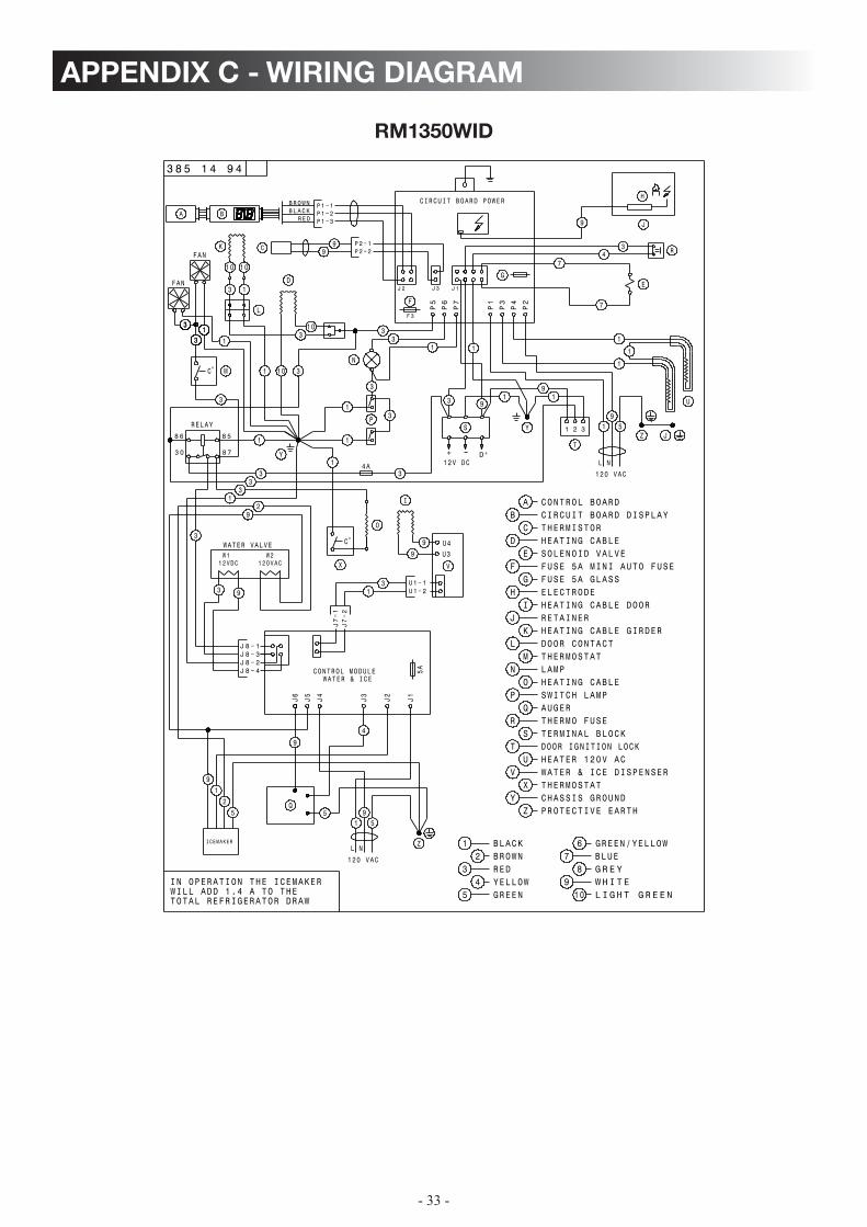
appendix c - wiring diagram
rm1350wid
+
L N
19
5
12V DC
CONTROL BOARDB
CD
EF
G
HEATING CABLETHERMISTOR
KJ
LM
N LAMPTHERMOSTATDOOR CONTACT
RETAINER
H
CIRCUIT BOARD DISPLAY
SOLENOID VALVE
HEATING CABLE GIRDER
IELECTRODE
O HEATING CABLEP SWITCH LAMP
3 8 5 1 4 9 4
RELAY
8 5
8 7
8 6
3 0
°
D+
S
TU
VX
HEATER 120V ACDOOR IGNITION LOCK
THERMOSTATCHASSIS GROUNDY
QTHERMO FUSERTERMINAL BLOCK
98
W H I T EG R E YBLUE
REDBROWNBLACK1
23
45
67
GREEN
GREEN/YELLOW
YELLOW10 L I G H T G R E E N
WATER VALVE W112VDC
W2120VAC
93
120 VAC
L N
19
5
120 VAC
Z
V
C
1
X
Y
1
°C M
4A
D
1 2 3
T
U
Z
P
N
13
3
1
1 10
103 3
3
13
1
1
11
33
3
3
3
9
3
3
O9
ICEMAKER
Y
Z PROTECTIVE EARTH
1
IN OPERATION THE ICEMAKERWILL ADD 1.4 A TO THETOTAL REFRIGERATOR DRAW
1010
K
L
3 1
J
FAN
13
FAN
1
33
J 8 − 1J 8 − 3
J 8 − 4J 8 − 2
5A
J4
J3
J6
J5
J2
J1
C ONTROL MODULE WATER & ICE
31
J7−2
J7−1
12
Q
AUGER
S
WATER & ICE DISPENSER
I
U3U4
A
HEATING CABLE DOOR
9
4
5
U1−1U1−2
9
9
9
12
5
P1−1P1−2P1−3
B
BROWNBLACK
REDA
P2−1P2−29
9C
P2
G
F
P6
P7
P4
P3
P1
F 3
P5
J 2 J3 J1
7
H
R4
J
E
7
9
3
CIRCUIT BOARD POWER
11
FUSE 5A MINI AUTO FUSEFUSE 5A GLASS
93
- 34 -
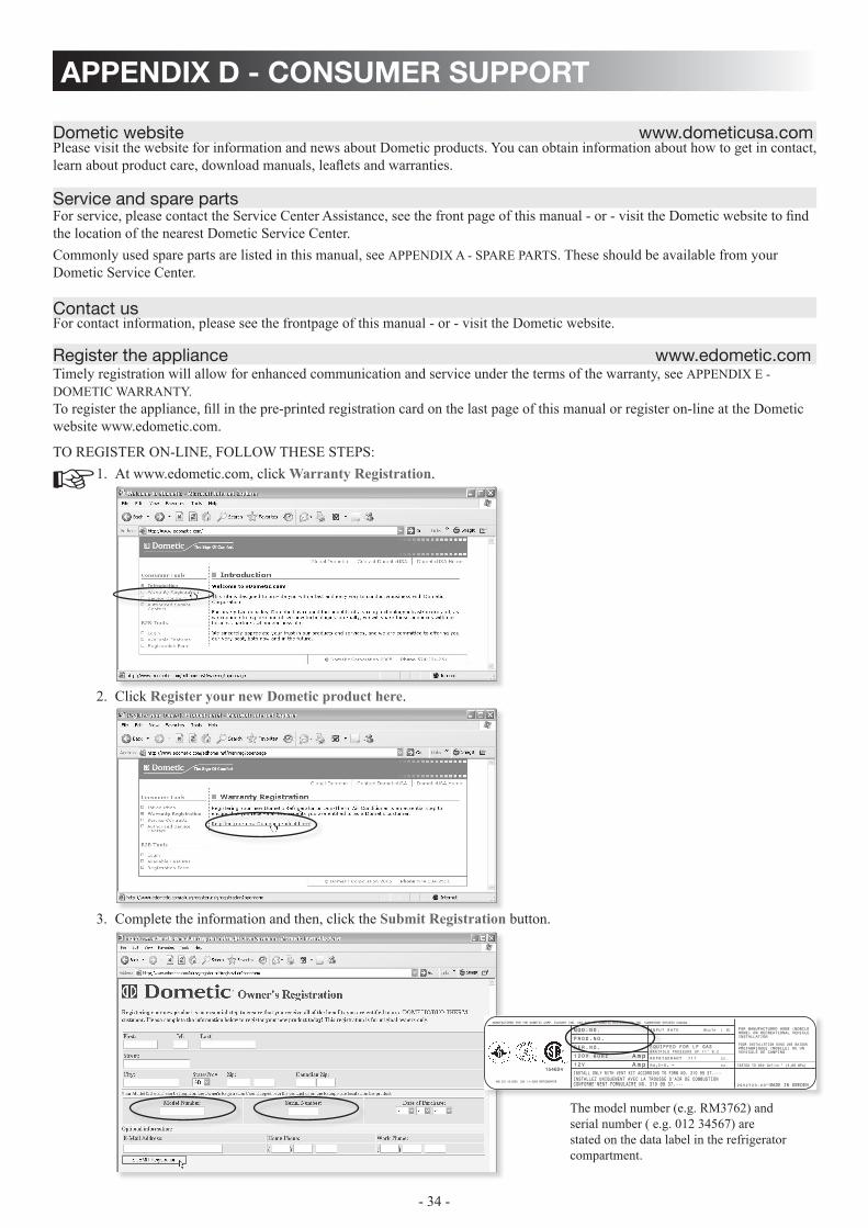
appendix d - consumer support
Please visit the website for information and news about Dometic products. you can obtain information about how to get in contact, learn about product care, download manuals, leaflets and warranties.
For service, please contact the Service Center Assistance, see the front page of this manual - or - visit the Dometic website to find the location of the nearest Dometic Service Center.Commonly used spare parts are listed in this manual, see APPENDIX A - SPARE PARTS. These should be available from your Dometic Service Center.
For contact information, please see the frontpage of this manual - or - visit the Dometic website.
Timely registration will allow for enhanced communication and service under the terms of the warranty, see APPENDIX E - DOMETIC WARRANTy. To register the appliance, fill in the pre-printed registration card on the last page of this manual or register on-line at the Dometic website www.edometic.com.
TO REGISTER ON-LINE, FOLLOW THESE STEPS: At www.edometic.com, click 1. Warranty Registration.
Click 2. Register your new Dometic product here.
Complete the information and then, click the 3. Submit Registration button.
service and spare parts
dometic website www .dometicusa .com
contact us
register the appliance www .edometic .com
The model number (e.g. RM3762) and serial number ( e.g. 012 34567) are stated on the data label in the refrigerator compartment.
- 35 -
congratulations, and thank you for purchasing the industry’s best built and best backed rv refrigerator . below you will find important warranty and maintenance information on dometic’s exclusive two (2) year warranty . please take a few moments and familiarize yourself with the program . We at dometic appreciate your business and are confident that you will have many years of trouble-free rv enjoyment .
limited two-year warranty dometic refrigeratorsThis warranty is made only to the first purchaser (herein after referred to as the “Original Purchaser”) who acquires the product 1. for his own use and is installed and operated within the continental United States and Canada.This warranty will be in effect for two years on parts and freight and two years on labor from the date of purchase by the Original 2. Purchaser. It is suggested that the original purchaser retain a copy of the dated bill of sale as evidence of the date of purchase.This warranty covers only specified parts, which shall be free from defects in material and workmanship under normal use. This 3. warranty does not cover conditions unrelated to the material and workmanship of the product. Such unrelated conditions include, but are not limited to: (a) damage not reported within the first 7 days of ownership; (b) faulty installation or installation that does not comply with RVIA stan dards, and any damage resulting from such; (c) the need for normal maintenance and any damage re-sulting from the failure to provide such maintenance; (d) failure to follow Sellers instructions for use of product; (e) any accident to or misuse of any part of this product and any alteration by anyone other than the Seller or its authorized representative; (f) any non-Dometic parts that are installed as replacement parts will void any warranty (implied or written); (g) blow out conditions; (h) radio frequency interference and electromagnetic interference; (i) 12V system chassis ground decay and corrosion; (j) puncture of foam cabinet or vacuum insulated panels after acknowledged receipt; (k) animal or insect infiltration which damages unit or inhibits performance; (l) abuse or misuse of electrical components.The specified parts covered by this warranty are as follows: Major components (cooling unit, LP gas valve, burner, burner hous-4. ing, electronic display, electronic module, evaporator fins, foam integrity, frame, thermister, spark probe, ignition wire, ice maker compressor, second absorption loop, display escutcheon, lower toe plate, humidity switch, frame heater mullion, ice maker mul-lion) are covered for parts and freight for two years and labor for two years from date of purchase. All other components that fail must be reported within the first 90 days of ownership in order to receive coverage of parts, freight and labor under warranty.This warranty requires the Original Purchaser to provide preventative maintenance on a yearly basis, starting at the anniversary 5. of his date of purchase. The Original Purchaser must keep a record of the preventative maintenance to keep the warranty in effect. Failure of the Original Purchaser in providing this annual maintenance may void the warranty. The preventative mainte-nance must be performed at a Dometic Authorized Service Center/Dealer. The preventative maintenance required is an inspec-tion, cleaning and full diagnostics performed on the entire electronic system, burner assembly, wiring and cooling unit. A copy of the receipt covering the main tenance checks must accompany the warranty claim during the second year of ownership. The cost of this preventative maintenance is the Original Purchaser’s responsibility and should take about one hour.In order to obtain the benefits of this warranty, the original purchaser must return the product which is found defective to the 6. Seller named below or to a Dometic Authorized Service Center during the period that this warranty is in effect. The original pur-chaser is responsible for all charges incurred in delivery of the product to the Seller or Dometic Authorized Service Center, and in pick up after the warranty service has been completed. To obtain the location of the nearest Authorized Service Center, please call 1-800-544-4881 or in Canada call 1-519-653-4390.Any item returned in the manner described in paragraph 6 will be examined by the Seller or the Authorized Dometic Service 7. Center. If it is found that the returned item was defective in material and workmanship, the Seller or the Authorized Dometic Service Center will repair the product per the terms outlined in paragraph 4. CONFIRM THE SERVICE AGENCy IS AN AU-THORIZED DOMETIC SERVICE CENTER. DO NOT PAy THE SERVICE AGENCy FOR WARRANTy REPAIRS. SUCH PAyMENTS WILL NOT BE REIMBURSED.The Seller does not authorize any person or company to create any warranty obligations or liability on their behalf. This warranty 8. is not extended by the length of time which you are deprived of the use of the product. Repairs and replacement parts provided under the terms of this warranty shall carry only the non-expired portion of this warranty.In no event shall either seller be liable for incidental or consequential damages. This includes any damage to another product or 9. products resulting from such a defect. Some states do not allow the exclusion or limitation of incidental or consequential dam-ages, so the above limitations may not apply.Any implied warranty, including the implied warranty of merchantability and fitness for any purpose, is limited to the duration 10. of this limited warranty. Some states do not allow limitations on how long an implied warranty can last, so the above limitation may not apply.THIS WARRANTy GIVE SPECIFIC LEGAL RIGHTS, yOU MAy ALSO HAVE OTHER RIGHTS WHICH VARy FROM 11. STATE TO STATE. No action to enforce this warranty shall be commenced later than ninety (90) days after the expiration of the warranty period. Claims must be submitted in writing to the Dometic Warranty Department for arbitration.All products (except those specifically built for commercial use) are warranted only when installed on vehicles built to R.V.I.A 12. and C.R.V.A, Z-240 Standards.The Seller reserves the right to change the design of any product without notice and with no obligation to make corresponding 13. changes in products previously manufactured.
DOMETIC, LLCWarranty Department
2320 Industrial ParkwayElkhart, IN 46516
Phone: 574-294-2511Fax: 574-389-3975
appendix e - dometic warranty
- 36 -
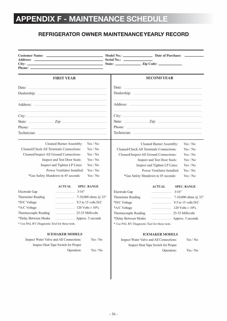
appendix f - maintenance schedule
refrigerator owner maintenance yearly record
Customer Name: Model No.: Date of Purchase:Address: Serial No.:
State:City: Zip Code:Phone:
FIRST YEAR
Date:Dealership:
Address:
City:State: Zip:Phone:Technician:
Cleaned Burner Assembly: Yes / NoCleaned/Check All Terminals Connections: Yes / No
Cleaned/Inspect All Ground Connections: Yes / NoInspect and Test Door Seals: Yes / No
Inspect and Tighten LP Lines: Yes / NoPower Ventilator Installed: Yes / No
*Gas Safety Shutdown in 45 seconds: Yes / No
ACTUAL SPEC. RANGE
Electrode Gap 3/16"Thermister Reading 7-10,000 ohms @ 32°*D/C Voltage 9.5 to 15 volts D/C*A/C Voltage 120 Volts ± 10%Thermocouple Reading 25-35 Millivolts*Delay Between Modes Approx. 5 seconds* Use PAL RV Diagnostic Tool for these tests.
ICEMAKER MODELS
Inspect Water Valve and All Connections: Yes / NoInspect Heat Tape Switch for Proper
Operation: Yes / No
SECOND YEAR
Date:Dealership:
Address:
City:State: Zip:Phone:Technician:
Cleaned Burner Assembly: Yes / NoCleaned/Check All Terminals Connections: Yes / No
Cleaned/Inspect All Ground Connections: Yes / NoInspect and Test Door Seals: Yes / No
Inspect and Tighten LP Lines: Yes / NoPower Ventilator Installed: Yes / No
*Gas Safety Shutdown in 45 seconds: Yes / No
ACTUAL SPEC. RANGE
Electrode Gap 3/16"Thermister Reading 7-10,000 ohms @ 32°*D/C Voltage 9.5 to 15 volts D/C*A/C Voltage 120 Volts ± 10%Thermocouple Reading 25-35 Millivolts*Delay Between Modes Approx. 5 seconds* Use PAL RV Diagnostic Tool for these tests.
ICEMAKER MODELS
Inspect Water Valve and All Connections: Yes / NoInspect Heat Tape Switch for Proper
Operation: Yes / No


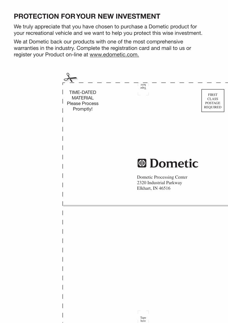
protection for your new investmentWe truly appreciate that you have chosen to purchase a dometic product for your recreational vehicle and we want to help you protect this wise investment .
We at dometic back our products with one of the most comprehensive warranties in the industry . complete the registration card and mail to us or register your product on-line at www .edometic .com .
Tape here
time-dated material
please process promptly!
FIRST CLASS
POSTAGE REqUIRED
Tape here
Dometic Processing Center2320 Industrial ParkwayElkhart, IN 46516
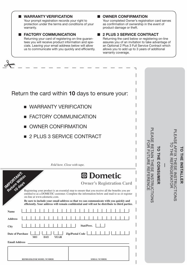
TO TH
E INSTA
LLERP
LEA
SE
AFFIX
THE
SE
INS
TRU
CTIO
NS
TO
THE
RE
FRIG
ER
ATOR
—TO
THE C
ON
SUM
ERP
LEA
SE
RE
TAIN
THE
SE
INS
TRU
CTIO
NS
FO
R FU
TUR
E R
EFE
RE
NC
E
w ■ arranty verificationyour prompt registration records your right to protection under the terms and conditions of your warranty.
owner confirmation ■your completed owner’s registration card serves as confirmation of ownership in the event of product damage or theft.
factory communication ■returning your card of registering on-line guaran-tees you will receive product information and spe-cials. leaving your email address below will allow us to communicate with you quickly and efficiently.
2 plus 3 service contract ■returning the card below or registering on-line assures you of an invitation to take advantage of an optional 2 plus 3 full Service contract which allows you to add up to 3 years of additional warranty coverage.
return the card within 10 days to ensure your:
Warranty verification ■
factory communication ■
oWner confirmation ■
2 plus 3 service contract ■
Fold here. Close with tape.
Email Address
REfRIgERATOR MODEL nuMbER sERIAL nuMbER
name
Address
City stat/Prov.
Zip/Postal CodeDate of PurchaseMO DAy yEAR
Registering your product is an essential step to ensure that you receive all the benefits you are entitled to as a DOMETIC customer. Complete the information below and mail to us or register on-line at www.edometic.com.
be sure to include your email address so that we can communicate with you quickly and efficiently. your address will remain confidential and will not be distribute to third parties.
Owner’s Registration Cardim
portant:
return
With
in
10 days