operating instructions compactrio...
TRANSCRIPT
OPERATING INSTRUCTIONS
CompactRIO cRIO-92154-Channel, ±10 V, 16-Bit Simultaneous Analog Input Module
™
cRIO-9215 Operating Instructions 2 ni.com
These operating instructions describe how to use the National Instruments cRIO-9215. In this document, the cRIO-9215 with screw terminal and cRIO-9215 with BNC are referred to inclusively as the cRIO-9215. For information about installing, configuring, and programming the CompactRIO system, refer to the CompactRIO Bookshelf at Start»All Programs»National Instruments»CompactRIO»Search the CompactRIO Bookshelf.
Safety GuidelinesOperate the cRIO-9215 only as described in these operating instructions.
Hot Surface This icon denotes that the component may be hot. Touching this component may result in bodily injury.
Safety Guidelines for Hazardous LocationsThe cRIO-9215 is suitable for use in Class I, Division 2, Groups A, B, C, and D hazardous locations; Class 1, Zone 2, AEx nC IIC T4 and Ex nC IIC T4 hazardous locations; and nonhazardous locations only. Follow these guidelines if you are installing the cRIO-9215

© National Instruments Corp. 3 cRIO-9215 Operating Instructions
in a potentially explosive environment. Not following these guidelines may result in serious injury or death.
Caution Do not disconnect I/O-side wires or connectors unless power has been switched off or the area is known to be nonhazardous.
Caution Do not remove modules unless power has been switched off or the area is known to be nonhazardous.
Caution Substitution of components may impair suitability for Class I, Division 2.
Caution For Zone 2 applications, install the CompactRIO system in an enclosure rated to at least IP 54 as defined by IEC 60529 and EN 60529.
Special Conditions for Safe Use in EuropeThis equipment has been evaluated as EEx nC IIC T4 equipment under DEMKO Certificate No. 03 ATEX 0324020X. Each module is marked II 3G and is suitable for use in Zone 2 hazardous locations.
cRIO-9215 Operating Instructions 4 ni.com
Safety Guidelines for Hazardous VoltagesYou can connect hazardous voltages only to the cRIO-9215 with screw terminal. Do not connect hazardous voltages to the cRIO-9215 with BNC.
If hazardous voltages are connected to the module, take the following precautions. A hazardous voltage is a voltage greater than 42.4 Vpeak or 60 VDC to earth ground.
Caution Ensure that hazardous voltage wiring is performed only by qualified personnel adhering to local electrical standards.
Caution Do not mix hazardous voltage circuits and human-accessible circuits on the same module.
Caution Make sure that devices and circuits connected to the module are properly insulated from human contact.
Caution When module terminals are live with hazardous voltages, make sure that the connectors are not accessible. You can use the cRIO-9932 connector kit or put the CompactRIO chassis in a suitably rated enclosure.
© National Instruments Corp. 5 cRIO-9215 Operating Instructions
Wiring the cRIO-9215The cRIO-9215 provides connections for four differential analog input channels. The cRIO-9215 with screw terminal has a 10-terminal detachable screw-terminal connector. The cRIO-9215 with BNC has four BNC connectors.
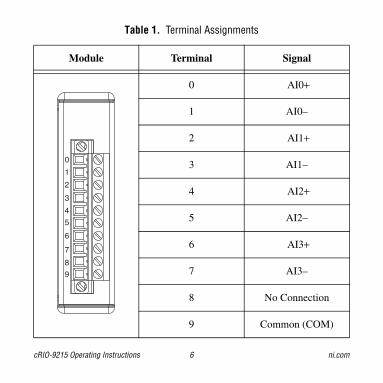
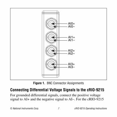
Each channel of the cRIO-9215 has a terminal or center pin to which you can connect the positive voltage signal, AI+, and a terminal or shield to which you can connect the negative voltage signal, AI–. The cRIO-9215 with screw terminal also has a common terminal, COM, that is internally connected to the isolated ground reference of the module. Refer to Table 1 for the terminal assignments of the cRIO-9215 with screw terminal. Refer to Figure 1 for the pin assignments of the cRIO-9215 with BNC.
cRIO-9215 Operating Instructions 6 ni.com
Table 1. Terminal Assignments
Module Terminal Signal
0 AI0+
1 AI0–
2 AI1+
3 AI1–
4 AI2+
5 AI2–
6 AI3+
7 AI3–
8 No Connection
9 Common (COM)
0
1
2
3
4
5
6
7
8
9
© National Instruments Corp. 7 cRIO-9215 Operating Instructions
Figure 1. BNC Connector Assignments
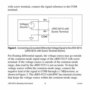
Connecting Differential Voltage Signals to the cRIO-9215For grounded differential signals, connect the positive voltage signal to AI+ and the negative signal to AI–. For the cRIO-9215
AI3+AI3–
AI2+AI2–
AI0+AI0–
AI1+AI1–
cRIO-9215 Operating Instructions 8 ni.com
with screw terminal, connect the signal reference to the COM terminal.
Figure 2. Connecting a Grounded Differential Voltage Signal to the cRIO-9215 (cRIO-9215 with Screw Terminal Shown)
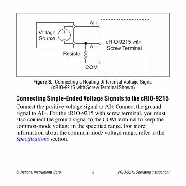
For floating differential signals, the voltage source may go outside of the common-mode signal range of the cRIO-9215 with screw terminal. If the voltage source is outside of the common-mode range, data read by the cRIO-9215 is not accurate. To keep the voltage source within the common-mode range, connect the negative lead of the signal to COM through a 1 MΩ resistor, as shown in Figure 3. The cRIO-9215 with BNC has internal circuitry that keeps the voltage source within the common-mode range.
cRIO-9215 withScrew TerminalAI–
AI+
+
–VoltageSource
COM
© National Instruments Corp. 9 cRIO-9215 Operating Instructions
Figure 3. Connecting a Floating Differential Voltage Signal (cRIO-9215 with Screw Terminal Shown)
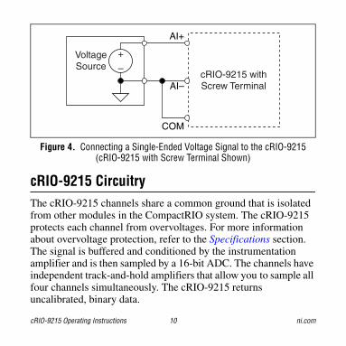
Connecting Single-Ended Voltage Signals to the cRIO-9215 Connect the positive voltage signal to AI+. Connect the ground signal to AI–. For the cRIO-9215 with screw terminal, you must also connect the ground signal to the COM terminal to keep the common-mode voltage in the specified range. For more information about the common-mode voltage range, refer to the Specifications section.
AI–
AI+
cRIO-9215 with Screw Terminal
COM
Resistor
+
–VoltageSource
cRIO-9215 Operating Instructions 10 ni.com
Figure 4. Connecting a Single-Ended Voltage Signal to the cRIO-9215 (cRIO-9215 with Screw Terminal Shown)
cRIO-9215 CircuitryThe cRIO-9215 channels share a common ground that is isolated from other modules in the CompactRIO system. The cRIO-9215 protects each channel from overvoltages. For more information about overvoltage protection, refer to the Specifications section. The signal is buffered and conditioned by the instrumentation amplifier and is then sampled by a 16-bit ADC. The channels have independent track-and-hold amplifiers that allow you to sample all four channels simultaneously. The cRIO-9215 returns uncalibrated, binary data.
cRIO-9215 withScrew TerminalAI–
AI+
+
–VoltageSource
COM

© National Instruments Corp. 11 cRIO-9215 Operating Instructions
Figure 5. Input Circuitry for One Channel on the cRIO-9215 with Screw Terminal
The cRIO-9215 with BNC has a resistor that ensures the input voltage does not drift outside of the common-mode range.
COM
cRIO-9215 with Screw Terminal
InstrumentationAmplifier
IsolatedADC
AI+ OvervoltageProtection
+
AI– OvervoltageProtection
–
cRIO-9215 Operating Instructions 12 ni.com
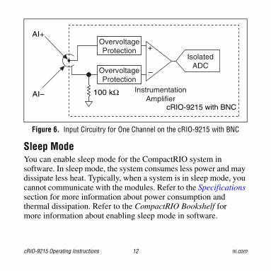
Figure 6. Input Circuitry for One Channel on the cRIO-9215 with BNC
Sleep ModeYou can enable sleep mode for the CompactRIO system in software. In sleep mode, the system consumes less power and may dissipate less heat. Typically, when a system is in sleep mode, you cannot communicate with the modules. Refer to the Specifications section for more information about power consumption and thermal dissipation. Refer to the CompactRIO Bookshelf for more information about enabling sleep mode in software.
cRIO-9215 with BNC
AI+
AI– InstrumentationAmplifier
IsolatedADC
OvervoltageProtection
OvervoltageProtection
+
–
100 kΩ
© National Instruments Corp. 13 cRIO-9215 Operating Instructions
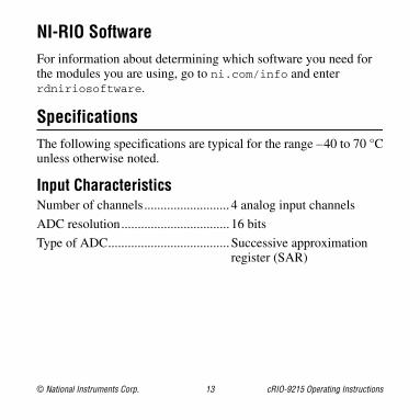
NI-RIO SoftwareFor information about determining which software you need for the modules you are using, go to ni.com/info and enter rdniriosoftware.
SpecificationsThe following specifications are typical for the range –40 to 70 °Cunless otherwise noted.
Input CharacteristicsNumber of channels.......................... 4 analog input channels
ADC resolution................................. 16 bits
Type of ADC..................................... Successive approximation register (SAR)
cRIO-9215 Operating Instructions 14 ni.com
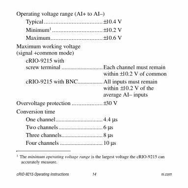
Operating voltage range (AI+ to AI–)Typical .................................... ±10.4 V
Minimum1 ............................... ±10.2 VMaximum................................ ±10.6 V
Maximum working voltage(signal + common mode)
cRIO-9215 with screw terminal ............................Each channel must remain
within ±10.2 V of commoncRIO-9215 with BNC.................All inputs must remain
within ±10.2 V of the average AI– inputs
Overvoltage protection ................... ±30 V
Conversion timeOne channel................................ 4.4 µsTwo channels .............................. 6 µsThree channels............................ 8 µsFour channels ............................. 10 µs
1 The minimum operating voltage range is the largest voltage the cRIO-9215 can accurately measure.
© National Instruments Corp. 15 cRIO-9215 Operating Instructions
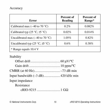
Accuracy
StabilityOffset drift .................................. 60 µV/ºCGain drift .................................... 10 ppm/ºC
CMRR (at 60 Hz).............................. –73 dB min
Input bandwidth (–3 dB)................... 420 kHz min
Input impedanceResistance
cRIO-9215 ........................... 1 GΩ
ErrorPercent of Reading
Percent of Range*
Calibrated max (–40 to 70 °C) 0.2% 0.082%
Calibrated typ (25 °C, ±5 °C) 0.02% 0.014%
Uncalibrated max (–40 to 70 °C) 1.05% 0.82%
Uncalibrated typ (25 °C, ±5 °C) 0.6% 0.38%
* Range equals 10.4 V
cRIO-9215 Operating Instructions 16 ni.com
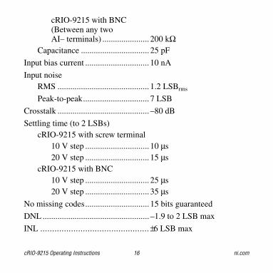
cRIO-9215 with BNC(Between any two AI– terminals) ...................... 200 kΩ
Capacitance ................................ 25 pF
Input bias current .............................. 10 nA
Input noiseRMS ........................................... 1.2 LSBrms
Peak-to-peak............................... 7 LSB
Crosstalk ........................................... –80 dB
Settling time (to 2 LSBs)cRIO-9215 with screw terminal
10 V step .............................. 10 µs20 V step .............................. 15 µs
cRIO-9215 with BNC10 V step .............................. 25 µs20 V step .............................. 35 µs
No missing codes.............................. 15 bits guaranteed
DNL .................................................. –1.9 to 2 LSB max
INL .............................................. ±6 LSB max
© National Instruments Corp. 17 cRIO-9215 Operating Instructions
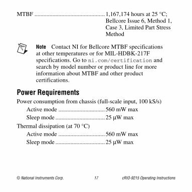
MTBF ............................................... 1,167,174 hours at 25 °C; Bellcore Issue 6, Method 1, Case 3, Limited Part Stress Method
Note Contact NI for Bellcore MTBF specifications at other temperatures or for MIL-HDBK-217F specifications. Go to ni.com/certification and search by model number or product line for more information about MTBF and other product certifications.
Power RequirementsPower consumption from chassis (full-scale input, 100 kS/s)
Active mode ............................... 560 mW maxSleep mode ................................. 25 µW max
Thermal dissipation (at 70 °C)Active mode ............................... 560 mW maxSleep mode ................................. 25 µW max
cRIO-9215 Operating Instructions 18 ni.com
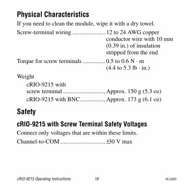
Physical CharacteristicsIf you need to clean the module, wipe it with a dry towel.
Screw-terminal wiring ...................... 12 to 24 AWG copper conductor wire with 10 mm (0.39 in.) of insulation stripped from the end
Torque for screw terminals ............... 0.5 to 0.6 N · m (4.4 to 5.3 lb · in.)
WeightcRIO-9215 withscrew terminal ............................Approx. 150 g (5.3 oz)cRIO-9215 with BNC.................Approx. 173 g (6.1 oz)
Safety
cRIO-9215 with Screw Terminal Safety VoltagesConnect only voltages that are within these limits.
Channel-to-COM ........................... ±30 V max

© National Instruments Corp. 19 cRIO-9215 Operating Instructions
IsolationChannel-to-channel ....................No isolation between
channelsChannel-to-earth ground
Withstand ............................. 2,300 Vrms, 1 minute max
Continuous ........................... 250 Vrms, Measurement Category II
Measurement Category II is for measurements performed on circuits directly connected to the electrical distribution system. This category refers to local-level electrical distribution, such as that provided by a standard wall outlet (for example, 115 V for U.S. or 230 V for Europe). Do not use this module with Measurement Category III or IV voltages.
cRIO-9215 with BNC Safety VoltagesConnect only voltages that are within these limits.
AI+-to-AI– .................................... ±30 V max

cRIO-9215 Operating Instructions 20 ni.com
IsolationChannel-to-channel ....................No isolation between
channelsChannel-to-earth ground
Withstand ............................. 1,500 Vrms, 1 minute max
Continuous ........................... 60 VDC, Measurement Category I
Measurement Category I is for measurements performed on circuits not directly connected to the electrical distribution system referred to as MAINS voltage. MAINS is a hazardous live electrical supply system that powers equipment. This category is for measurements of voltages from specially protected secondary circuits. Such voltage measurements include signal levels, special equipment, limited-energy parts of equipment, circuits powered by regulated low-voltage sources, and electronics. Do not use this module with Measurement Category II, III, or IV voltages.
© National Instruments Corp. 21 cRIO-9215 Operating Instructions
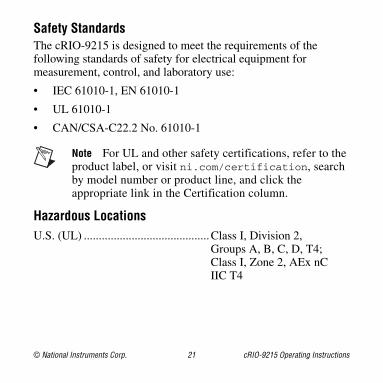
Safety StandardsThe cRIO-9215 is designed to meet the requirements of the following standards of safety for electrical equipment for measurement, control, and laboratory use:
• IEC 61010-1, EN 61010-1
• UL 61010-1
• CAN/CSA-C22.2 No. 61010-1
Note For UL and other safety certifications, refer to the product label, or visit ni.com/certification, search by model number or product line, and click the appropriate link in the Certification column.
Hazardous LocationsU.S. (UL) ..........................................Class I, Division 2,
Groups A, B, C, D, T4;Class I, Zone 2, AEx nC IIC T4
cRIO-9215 Operating Instructions 22 ni.com
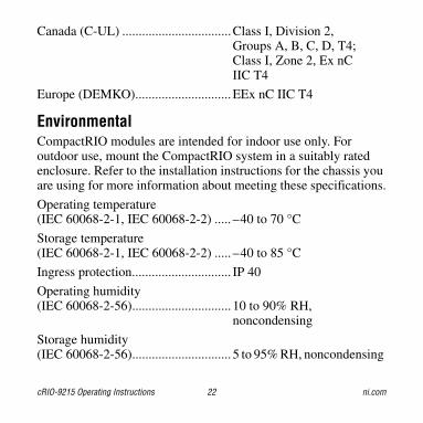
Canada (C-UL) .................................Class I, Division 2, Groups A, B, C, D, T4;Class I, Zone 2, Ex nC IIC T4
Europe (DEMKO).............................EEx nC IIC T4
EnvironmentalCompactRIO modules are intended for indoor use only. For outdoor use, mount the CompactRIO system in a suitably rated enclosure. Refer to the installation instructions for the chassis you are using for more information about meeting these specifications.
Operating temperature (IEC 60068-2-1, IEC 60068-2-2) ..... –40 to 70 °C
Storage temperature(IEC 60068-2-1, IEC 60068-2-2) ..... –40 to 85 °C
Ingress protection.............................. IP 40
Operating humidity(IEC 60068-2-56).............................. 10 to 90% RH,
noncondensing
Storage humidity(IEC 60068-2-56).............................. 5 to 95% RH, noncondensing
© National Instruments Corp. 23 cRIO-9215 Operating Instructions
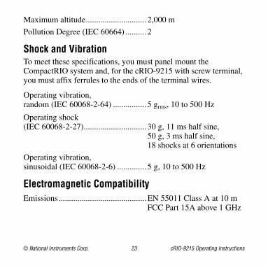
Maximum altitude............................. 2,000 m
Pollution Degree (IEC 60664) .......... 2
Shock and VibrationTo meet these specifications, you must panel mount the CompactRIO system and, for the cRIO-9215 with screw terminal, you must affix ferrules to the ends of the terminal wires.
Operating vibration,random (IEC 60068-2-64) ................ 5 grms, 10 to 500 Hz
Operating shock(IEC 60068-2-27).............................. 30 g, 11 ms half sine,
50 g, 3 ms half sine,18 shocks at 6 orientations
Operating vibration,sinusoidal (IEC 60068-2-6) .............. 5 g, 10 to 500 Hz
Electromagnetic CompatibilityEmissions..........................................EN 55011 Class A at 10 m
FCC Part 15A above 1 GHz
cRIO-9215 Operating Instructions 24 ni.com
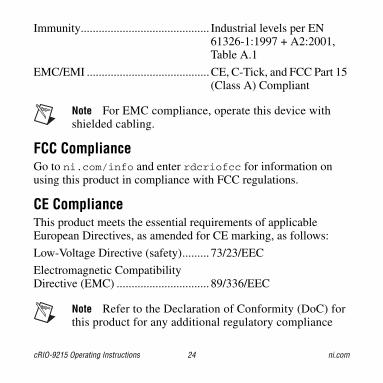
Immunity........................................... Industrial levels per EN 61326-1:1997 + A2:2001, Table A.1
EMC/EMI .........................................CE, C-Tick, and FCC Part 15 (Class A) Compliant
Note For EMC compliance, operate this device with shielded cabling.
FCC ComplianceGo to ni.com/info and enter rdcriofcc for information on using this product in compliance with FCC regulations.
CE ComplianceThis product meets the essential requirements of applicable European Directives, as amended for CE marking, as follows:
Low-Voltage Directive (safety)......... 73/23/EEC
Electromagnetic CompatibilityDirective (EMC) ............................... 89/336/EEC
Note Refer to the Declaration of Conformity (DoC) for this product for any additional regulatory compliance
© National Instruments Corp. 25 cRIO-9215 Operating Instructions
information. To obtain the DoC for this product, visit ni.com/certification, search by model number or product line, and click the appropriate link in the Certification column.
CalibrationYou can obtain the calibration certificate for the cRIO-9215 at ni.com/calibration.
Calibration interval ........................... 1 year
National Instruments Contact InformationNational Instruments corporate headquarters is located at 11500 North Mopac Expressway, Austin, Texas, 78759-3504. National Instruments also has offices located around the world to help address your support needs. For telephone support in the United States, create your service request at ni.com/support and follow the calling instructions or dial 512 795 8248. For telephone support outside the United States, contact your local branch office:
Australia 1800 300 800, Austria 43 0 662 45 79 90 0, Belgium 32 0 2 757 00 20, Brazil 55 11 3262 3599,
cRIO-9215 Operating Instructions 26 ni.com
Canada (Calgary) 403 274 9391, Canada (Ottawa) 613 233 5949, Canada (Québec) 450 510 3055, Canada (Toronto) 905 785 0085, Canada (Vancouver) 604 685 7530, China 86 21 6555 7838, Czech Republic 420 224 235 774, Denmark 45 45 76 26 00, Finland 385 0 9 725 725 11, France 33 0 1 48 14 24 24, Germany 49 0 89 741 31 30, India 91 80 51190000, Israel 972 0 3 6393737, Italy 39 02 413091, Japan 81 3 5472 2970, Korea 82 02 3451 3400, Malaysia 603 9131 0918, Mexico 01 800 010 0793, Netherlands 31 0 348 433 466, New Zealand 0800 553 322, Norway 47 0 66 90 76 60, Poland 48 22 3390150, Portugal 351 210 311 210, Russia 7 095 783 68 51, Singapore 65 6226 5886, Slovenia 386 3 425 4200, South Africa 27 0 11 805 8197, Spain 34 91 640 0085, Sweden 46 0 8 587 895 00, Switzerland 41 56 200 51 51, Taiwan 886 2 2528 7227, Thailand 662 992 7519, United Kingdom 44 0 1635 523545
© 2004–2005 National Instruments Corp. All rights reserved.
373779B-01 Jan05
National Instruments, NI, ni.com, and LabVIEW are trademarks of National Instruments Corporation. Refer to the Terms of Use section on ni.com/legal for more information about National Instruments trademarks. Other product and company names mentioned herein are trademarks or trade names of their respective companies. For patents covering National Instruments products, refer to the appropriate location: Help»Patents in your software, the patents.txt file on your CD, or ni.com/patents.