97-03-12
TRANSCRIPT

SUPPLEMENTAL SPECIFICATIONS
S. C. File No. Page 1
March 12, 1997
METRIC STRUCTURAL STEEL FASTENERS
This Supplemental Specification shall govern over any provision in the Standard Specifications Section709.06 "Bolts" and Section 709.36 "Connections Using High Strength Bolts".
A. Scope. This specification governs the furnishing and installation of an assembly composed of a bolt, nut,direct tension indicator and washers as required.
All high-strength bolts, nuts, washers, and direct tension indicators shall be furnished in accordance with theappropriate AASHTO Materials Specifications as amended and revised herein.
Additional requirements for field or shop installation of AASHTO M 164M (ASTM A 325M) high strength boltsare also included. These additional requirements supplement AASHTO Standard Specifications for HighwayBridges, Fifteenth Edition, Division II, Section 11.
B. Specifications.
B1. All bolts shall meet either the requirements of AASHTO M 164M (ASTM A 325M) or AASHTO M253M (ASTM A 490M ) as applicable and these revisions.
B2. All nuts shall meet the requirements of AASHTO M 291M (ASTM A 563M).
B3. All washers shall meet the requirements of ASTM F 436M and these revisions.
B4. The Direct Tension Indicators shall comply with ASTM F 959M -94, Type 8.8, and shall be acceptedand installed in accordance with the attached Appendix A. "Procedure for Identification andInstallation of High Strength Bolts with Direct Tension Indicators. (DTI’s)"
C. Manufacturing
C1. Bolts
1. All Type 1 and Type 2 bolts shall be mechanically galvanized in accordance with AASHTO M 298(ASTM B 695 Class 50). When atmospheric corrosion resistant steel, AASHTO M 270M Grade345W (ASTM A 709M, Grade 345W) is required by the plans, Type 3 bolts shall be used andshall be non-galvanized.
2. Hardness for bolt diameters 16 mm to 36 mm inclusive shall be as noted below:
Hardness NumberBolt Size, mm : Vickers Rockwell16 mm to 36 mm Min Max Min MaxA-325M 255 336 23 33A-490M 327 382 33 39
C2. Nuts
1. Nuts shall be AASHTO M 291M, Grade 12 or 10S3. ( ASTM A 563M). Nuts for Type 1 and Type2 bolts shall be mechanically galvanized in accordance with AASHTO M 298 Class 50 ( ASTM B695, Class 50). Nuts for Type 3 bolts shall be Class 8S3, plain (non-galvanized).

SUPPLEMENTAL SPECIFICATIONS
S. C. File No. Page 2
2. Nuts shall be tapped oversize the minimum amount required for proper assembly. The amount ofovertap in the nut shall be such that the nut will assemble freely on the bolt in the coatedcondition and shall meet the mechanical requirements of AASHTO M 291M (ASTM A 563M) andthe rotational capacity test herein (the overtapping requirements of AASHTO M 291M (ASTM A563M) shall be considered maximum value).
3. Galvanized nuts shall be lubricated with a water-soluble lubricant containing a dye of any colorthat contrasts with the color of the galvanizing.
C3. Washers. Washers for Type 1 and Type 2 bolts shall be mechanically galvanized in accordance withAASHTO M 298, Class 50. Type 3 washers shall not be galvanized.
C4. Direct Tension Indicators. The Direct Tension Indicators (DTIs) for Type 1, Type 2, and Type 3 boltsshall be mechanically galvanized in accordance with AASHTO M 298, Class 50 (ASTM B-695, Class50). In addition, DTIs for Type 3 bolts shall be epoxy coated with a black color.
C5. Marking. All bolts, nuts and washers shall be marked in accordance with the appropriateAASHTO/ASTM Specifications.
D. Testing
D1. Bolts
1. Proof load tests (ASTM F 606M Method 1) are required. Minimum frequency of tests shall be asspecified in AASHTO M 164M (ASTM A 325M) paragraph 9.3.4.
2. Wedge tests on full size bolts (ASTM F 606M) paragraph 3.5) are required. Tests shall beperformed after galvanizing. Minimum frequency of tests shall be as specified in AASHTO M164M (ASTM A 325M) paragraph 9.3.4.
3. The thickness of the zinc coating shall be measured. Measurements shall be taken on thewrench flats or top of bolt head.
D2. Nuts
1. Proof load tests (ASTM F 606M paragraph 4.2) are required. Minimum frequency of tests shall beas specified in AASHTO M 291M (ASTM A 563M) paragraph 8.3. Tests shall be performed aftergalvanizing, overtapping and lubricating.
2. The thickness of the zinc coating shall be measured. Measurements shall be taken on thewrench flats.
D3. Washers
1. Hardness testing shall be performed after galvanizing. (Coating shall be removed prior to takinghardness measurements).
2. The thickness of the zinc coating shall be measured.
D4. Direct Tension Indicators (DTIs). The DTIs shall be tested in accordance with ASTM F 959M-94.
D5. Assembly and Verification
1. Rotational capacity tests are required and shall be performed after galvanizing on all bolt, nut andwasher assemblies by the manufacturer or distributor prior to shipping. Washers are required aspart of the test.

SUPPLEMENTAL SPECIFICATIONS
S. C. File No. Page 3
The following shall apply:
a. The rotational-capacity test shall be performed in accordance with the requirementscontained in this special provision.
b. Each possible combination of bolt production lot, nut lot and washer lot shall be tested as anassembly. Three assemblies of each combination of materials shall be sampled by theDepartment for verification testing.
c. A rotational-capacity lot number shall be assigned to each combination of lots tested.
d. The minimum frequency of testing shall be two assemblies per rotational-capacity lot.
e. The bolt, nut and washer assembly shall be assembled in a Skidmore-Wilhelm Calibrator oran acceptable equivalent device (Note - this requirement supersedes the current AASHTO M164M (ASTM A 325M) requirement that the test be performed in a steel joint). For guidancein performing the test, use the procedure for long bolts as detailed in Appendix B. For shortbolts which are too short to be assembled in the Skidmore-Wilhelm Calibrator, see SectionD5.1i. (DTIs are not included in this rotational capacity test).
f. The minimum rotation, from an initial tension of 10% of the specified minimum installationtension shall be:
240º (2/3 turn) for bolt lengths < 4 diameters360º (1 turn) bolt lengths > 4 diameters and < 8 diameters480º (1 1/3 turn) for bolt lengths > 8 diameters and <12 diameters(Note: that these values differ from the AASHTO M 164M (ASTM A 325M )Specifications.
g. The tension at the above rotation shall be equal to or greater than 1.15 times the requiredinstallation tension. The installation tension and the tension for the turn tests are shownbelow:
MINIMUM INSTALLATION TENSION REQUIREMENTSAND TURN TEST TENSION
(Table X1.1, M-164M / M-253M)Tension in kilonewtons, kN
Diameter, mm 16 20 22 24 27 30 36A 325M kN (*1 ) 91 142 176 205 267 326 475Turn Test
A 325M, kN
(*2) 105 163 202 236 307 375 546
A 490M kN (*1 )114 179 221 257 334 408 595Turn Test
A 490M kN
(*2) 131 206 254 296 384 469 684
(*1 ) Installation Tension Equals 70% (Min. Tensile Strength)(*2) Turn Test Tension Equals 1.15 [70% (Min. Tensile Strength)]
h. After the required installation tension listed above has-been exceeded, one reading oftension and torque shall be taken and recorded. The torque value shall conform to thefollowing:
Torque < 0.25 PD
Where…Torque = measured torque (Newton meters, N.m)P = Turn test tension (Newtons, N)D = bolt diameters (meters, m)

SUPPLEMENTAL SPECIFICATIONS
S. C. File No. Page 4
i. Bolts that are too short to test in a Skidmore-Wilhelm Calibrator may be tested in a steel joint.The tension requirement of Section D5.1g need not apply. The maximum torque requirementof Section D5.1h shall be computed using a value of P equal to the turn test tension show inthe table in Section D5.1g. For guidance in performing the test, use the procedure for shortbolts as detailed in Appendix C.
j. Failure of any portion of the Rotational Capacity (RC) test for either of the two samples testedshall constitute failure of the RC lot.
D6. Reporting
1. The results of all tests (including the zinc coating thickness) required herein and in theappropriate AASHTO specifications shall be recorded on the appropriate document.
2. Location where tests are performed and date of tests shall be reported on the appropriatedocument.
D7. Witnessing
1. The tests need not be witnessed by an inspection agency; however, the manufacturer ordistributor that performs the tests shall certify that the results recorded are accurate.
E. Documentation
E1. Mill Test Report(s) (MTR)
1. MTR shall be furnished for all mill steel used in the manufacture of the bolts, nuts and washers.
2. MTR shall indicate the place where the material was melted and manufactured.
E2. Manufacturer Certified Test Report(s) (MCTR)
1. The manufacturer of the bolts, nuts and washers shall furnish test report (MCTR) for the itemfurnished.
2. Each MCTR shall show the relevant information required in accordance with Section D6.
3. The manufacturer performing the rotational capacity test shall include on the MCTR:
a. The lot number of each of the items tested.
b. The rotational-capacity lot number as required in Section D5.1c.
c. The results of the test required in Section D5.
d. The pertinent information required in Section D6.2
e. A statement that MCTR for the items are in conformance to this specification and theappropriate AASHTO specifications.
f. The location where the bolt assembly components were manufactured.
E3. Distributor Certified Test Report(s) (DCTR)
1. The DCTR shall include MCTR above for the various bolt assembly components.

SUPPLEMENTAL SPECIFICATIONS
S. C. File No. Page 5
2. The rotational capacity test may be performed by a distributor (in lieu of a manufacturer) andreported on the DCTR.
3. The DCTR shall show the results of the tests required in Section D5.
4. The DCTR shall also show the pertinent information required in Section D6.2.
5. The DCTR shall show the rotational-capacity lot number as required in Section D5.1c
6. The DCTR shall certify that the MCTR are in conformance to this specification and theappropriate AASHTO specifications.
F. Shipping
F1. Each container shall be permanently marked on the side of the container with the rotational-capacitylot number such that identification will be possible at any stage prior to installation.
F2. The appropriate MTR, MCTR or DCTR shall be supplied to the owner through the Contractor.
G. Installation
The following requirements for installation apply in addition to the specifications in AASHTO Division II,Section 11 when high strength bolts are installed in the field or shop.
G1. Bolts shall be installed in accordance with AASHTO Division II Article 11.5.6.4. During installation,regardless of the tightening method used, particular care should be exercised so that the snug tightcondition as defined in Article 11.5.6.4.4 is achieved. Snug tight is defined as the tightness thatexists when the plies of the joint are in firm contact. Hardened washers are required under the turnedelement for all installation methods.
G2. The rotational capacity test described in Section D5 above shall be performed on each rotationalcapacity lot prior to the start of bolt installation. Hardened steel washers are required as part of thetest.
G3. The Contractor shall provide a Skidmore-Wilhelm tension calibrator or another acceptable equivalenttension measuring device and a dial type torque wrench of suitable range at each job site duringerection. Periodic testing shall be performed to assure compliance with the installation testprocedures required in AASHTO Division II, Article 11.5.6.4. Bolts that are too short for theSkidmore-Wilhelm Calibrator may be tested using direct tension indicators (DTIs). The DTIs must becalibrated in the Skidmore-Wilhelm Calibrator using longer bolts.
G4. Periodic retesting shall be conducted as directed by the Engineer to confirm that storage has notreduced the effectiveness of the lubricant. Retesting shall be performed by the Contractor andwitnessed by the Engineer. The Lot of failing assemblies shall be rejected for use.
G5. Lubrication
1. Galvanized nuts shall be checked to verify that a visible lubricant is on the threads.
2. When the bolt head is to become the turned element in assembly, a lubricant approved by theEngineer shall be added to the washer face under the bolt head.
3. Weathered or rusted bolts or nuts not satisfying the requirements of G2, G3, or G4 above shallbe rejected. The Contractor may submit, for approval, a procedure for cleaning and relubricatingrejected fasteners. Recleaned or relubricated bolt, nut and washer assemblies shall be retestedin accordance with G2 above prior to installation.
SUPPLEMENTAL SPECIFICATIONS
S. C. File No. Page 6
G6. Bolt, nut and washer combinations as installed shall be from a lot represented by an acceptedrotational capacity test as certified by the manufacturer or distributor.
H. Measurement and Payment
No separate measurement or payment will be made for fasteners since they are considered incidental to thecontract price bid for Structural Steel.
SUPPLEMENTAL SPECIFICATIONS
S. C. File No. Page 7
March 12, 1997APPENDIX A
PROCEDURE FOR VERIFICATION AND INSTALLATION OF HIGHSTRENGTH BOLTS WITH DIRECT TENSION INDICATORS
(DTIs)
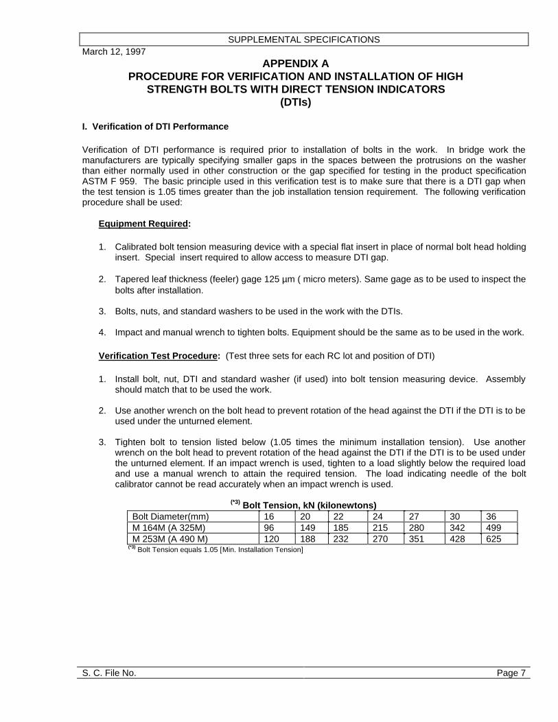
I. Verification of DTI Performance
Verification of DTI performance is required prior to installation of bolts in the work. In bridge work themanufacturers are typically specifying smaller gaps in the spaces between the protrusions on the washerthan either normally used in other construction or the gap specified for testing in the product specificationASTM F 959. The basic principle used in this verification test is to make sure that there is a DTI gap whenthe test tension is 1.05 times greater than the job installation tension requirement. The following verificationprocedure shall be used:
Equipment Required:
1. Calibrated bolt tension measuring device with a special flat insert in place of normal bolt head holdinginsert. Special insert required to allow access to measure DTI gap.
2. Tapered leaf thickness (feeler) gage 125 µm ( micro meters). Same gage as to be used to inspect thebolts after installation.
3. Bolts, nuts, and standard washers to be used in the work with the DTIs.
4. Impact and manual wrench to tighten bolts. Equipment should be the same as to be used in the work.
Verification Test Procedure: (Test three sets for each RC lot and position of DTI)
1. Install bolt, nut, DTI and standard washer (if used) into bolt tension measuring device. Assemblyshould match that to be used the work.
2. Use another wrench on the bolt head to prevent rotation of the head against the DTI if the DTI is to beused under the unturned element.
3. Tighten bolt to tension listed below (1.05 times the minimum installation tension). Use anotherwrench on the bolt head to prevent rotation of the head against the DTI if the DTI is to be used underthe unturned element. If an impact wrench is used, tighten to a load slightly below the required loadand use a manual wrench to attain the required tension. The load indicating needle of the boltcalibrator cannot be read accurately when an impact wrench is used.
(*3) Bolt Tension, kN (kilonewtons)Bolt Diameter(mm) 16 20 22 24 27 30 36M 164M (A 325M) 96 149 185 215 280 342 499M 253M (A 490 M) 120 188 232 270 351 428 625
(*3) Bolt Tension equals 1.05 [Min. Installation Tension]

SUPPLEMENTAL SPECIFICATIONS
S. C. File No. Page 8
4. Determine and record the number of spaces between the protrusion on the DTI that a 125µmthickness gage is refused. The total number of spaces in the various sizes and grade of DTIs isshown below.
Number of Spaces on DTIBolt Diameter (mm) 16 20 22 24 27 30 36M 164M (A 325M) 4 5 5 5 6 7 8M 253M (A 490M) 4 6 6 6 7 8 9
5. The number of spaces which the 125µm gage is refused should not exceed the number given in thetable below. If the number of spaces exceeds the number in the table, the DTI fails the verificationtest.
Verification Criteria*Number of spaces in washer 4 5 6 7 8 9Max. number spaces gage isrefused
1 2 2 3 3 4
*If the test is a coated DTI under the turned element the maximum number of spaces the gage isrefused is the number of spaces on the washer minus one .
6. The bolts should be further tightened to the smallest gap to be allowed in the work. Normally, thissmallest gap condition is achieved when the gaps at all the spaces are less than 125µm (or a gapsize as approved by the Engineer) and not all gaps completely closed. When such a condition isachieved , the 125µm gage is refused at all spaces but a visible gap exists in at least one space.Note the load in the bolt at the smallest gap. The bolts in this installation verification test and in theactual installation should not be tightened to a no visible gap condition when all the gaps arecompletely closed. The load in the bolt becomes indeterminate when no gap exists. It is possible tocause failure by tightening beyond complete crushing of the washer. The bolt load at this smallestgap should not cause excessive permanent inelastic deformation of the fastener. The degree ofinelastic deformation is judged by removing the fastener from the test apparatus and turning the nutby hand the full length of the threads on the bolt after the test.
7 Remove the bolt from the calibrator and turn the nut on the threads of the bolt by hand. The nutshould be able to be turned on the complete length of the threads, excluding the thread runout.Alternatively, if the nut is unable to go the full length , but the load at the minimum DTI gap (measuredin step 6 above) is less than 95% of the bolt tension recorded at the nut rotation required in SectionD5.1.f. for the rotational-capacity test, the assembly, including the DTI, is deemed to have passed thetest. If the nut cannot be run the full thread length, and if the load at the smallest gap condition isgreater than the 95% of the bolt tension recorded at the nut rotation required for the rotational-capacity test, the load required for the smallest gap in step 6 is too large and the DTI lot shall berejected.
Short Bolts.Bolts from Rotational Capacity (RC) lots too short to fit in the tension measuring device shall betested in accordance with Section 5D.1.i. of the Special Provisions by tightening to the minimum DTIgap (measured in step 6 above) and checked in accordance with step 7. The 95% alternative cannotbe used since short bolts are not tested in the tension measuring device for rotational capacity. TheDTI used with the short bolt should be checked in accordance with step 1 through 5 using a longerbolt in the tension measuring device.

SUPPLEMENTAL SPECIFICATIONS
S. C. File No. Page 9
II Installation:
1. The use of a DTI under the unturned bolt head requires that the element bearing against the DTI notturn. Two men are required: One to operate the wrench, and the other to prevent turning of theelement with the DTI and to monitor the gap. If the DTI is used under the turned element, anadditional hardened washer must be used between the turning element and the protrusion on theDTI.
2. Snug the connection to compact the joint. The DTI should be inspected after snugging and the gapschecked. If the number of spaces in which the 125µm gage is refused exceeds the value in the tableshown above in step 5 of the verification test, the bolt must be removed and another DTI installed.The bolt should be resnugged.
3. Tighten the bolts systematically to the inspection gap. The number of spaces in which the 125µmgage is refused should be equal or greater than the number shown in the table below. Tighteningbeyond the smallest gap established above in steps 6 and 7 is not allowed. Bolts which have a DTIwith a smaller gap or no gap shall be replaced and the bolts tightened with a new DTI.
INSPECTION CRITERIA *Number of spaces inwasher
4 5 6 7 8 9
Minimum spaces gageis refused
2 3 3 4 4 5
* The gage shall be refused in all spaces when a coated DTI is used under the turned element.

SUPPLEMENTAL SPECIFICATIONS
S. C. File No. Page 10
March 12, 1997APPENDIX B
PROCEDURE FOR PERFORMING ROTATIONAL CAPACITY TEST(LONG BOLTS IN TENSION CALIBRATOR)
EQUIPMENT REQUIRED
1. Calibrated bolt tension measuring device of size required for bolts to be tested. Mark off a verticalline and line 1/3 of a turn, 120 degrees; and 2/3 of a turn, 240 degrees, from vertical in a clockwisedirection on the face plate of the calibrator.
2. Calibrated torque wrench.
3. Spacers and/or washers with hole size no larger than 2 mm greater than bolt to be tested.
4. Steel section to mount bolt calibrator. Flange of girder or cross frame accessible from the ground issatisfactory.
PROCEDURE
1. Install nut on bolt and measure stick out of bolt when 3 to 5 threads of the bolt are located betweenthe bearing face of the nut and the bolt head. Measure the bolt length, the distance from the end ofthe threaded shank to the underside of the bolt head.
2. Install the bolt into the tension calibrator and install the required number of shim plates and/or washer(one washer under the nut must always be used) to produce the thread stickout measured in Step 1.
3. Tighten bolt using a hand wrench to the snug tensions listed below (-0 Newtons, +10% of minimuminstallation tension:
(*4) Snug-tight Tension Load, kN ( kilonewtons)Bolt Diameter, mm 16 20 22 24 27 30 36A 325M Snug TightTension Minimum
9 14 18 21 27 33 48
A 490M Snug- TightTension- Minimum,
11 18 22 26 33 41 60
(*4) 10% [Min. Installation Tension]
4. Match mark the nut to the vertical stripe on the face plate of the bolt calibrator.
5. Using the calibrated manual torque wrench, tighten the bolt to at least the tension listed below andrecord the torque required to reach the tension and the value of the bolt tension. Torque must bemeasured with the nut in motion.
Minimum Installation Tension,kN (kilonewtons)Bolt Diameter, mm 16 20 22 24 27 30 36Tension A 325Mbolts.
91 142 176 205 267 326 475
Tension A 490M bolts 114 179 221 257 334 408 595

SUPPLEMENTAL SPECIFICATIONS
S. C. File No. Page 11
6. Further tighten the bolt to the rotation listed below. The rotation is measured from the initial markingin Step 4. Record the bolt tension. Assemblies which fail prior to this rotation either by stripping orfracture fail the test.
ROTATIONBolt Length(measured in Step1)
4 x boltdiameter orless
Greater than 4 butno more than 8x boltdiameter.
Greater than 8xbolt diameter.
Required Rotation 2/3 1 1-1/3
7. The bolt tension measured in Step 6 after the required rotation must equal or exceed the values inthe table shown below. Assemblies which do not meet this tension have failed the test (Value is115% of Minimum Installation Tension).
TURN TEST BOLT TENSION, kN ( kilonewtons)Bolt Diameter, mm 16 20 22 24 27 30 36A 325M 105 163 202 236 307 375 546 A 490M 131 206 254 296 384 469 684
8. Loosen and remove nut, and examine the threads on the nut and bolt. No signs of thread shearfailure, stripping or torsional failure of the bolt should be evident. Assemblies which have evidence ofstripping have failed the test.
9. Calculate and record the value of 0.25x the tension (Newtons) measured in Step 5 x the bolt diameterin meters. The torque measured and recorded in Step 5 must be equal to or less than this calculatedvalue. Assemblies with torque values exceeding this calculated value failed the test.

SUPPLEMENTAL SPECIFICATIONS
S. C. File No. Page 12
March 12, 1997
APPENDIX CPROCEDURE FOR PERFORMING ROTATIONAL CAPACITY TEST
(BOLTS TOO SHORT TO FIT TENSION CALIBRATOR)
EQUIPMENT REQUIRED
1. Calibrated torque wrench and a spud wrench or equivalent.
2. Spacers and/or washers with hole size no larger than 2 mm. greater than bolt to be tested.
3. Steel section with normal size hole to install bolt. Any available splice hole can be used with a platethickness that will provide the number of threads under the nut required in Step 1 below. Mark off avertical line and line 1/3 of a turn, 120 degrees; 1/2 of a turn, 180 degrees; and 2/3 of a turn, 240degrees, from vertical in a clockwise direction on the plate.
PROCEDURE
1. Install nut on bolt and measure stick out of bolt when 3 to 5 threads of the bolt are located betweenthe bearing face of the nut and the bolt head. Measure the bolt length, the distance from the end ofthe threaded shank to the underside of the bolt head.
2. Install the bolt into the hole and install the required number of shim plates and/or washers (onewasher under the nut must always be used) to produce the thread stickout measured in Step 1.
3. Snug the bolt using a hand wrench. The snug condition should be the normal effort applied to a 12inch long wrench. The applied torque should not exceed 20% of the torque determined in Step 5 ofAppendix B.
4. Match mark the nut to the vertical strip on the plate.
5. Tighten the bolt by turning the nut using the torque wrench to the rotation listed below. A secondwrench must be used to prevent rotation of the bolt head during tightening. Record the torquerequired to reach this rotation. Torque must be measured with the nut in motion.
Rotation for both A 325M and A 490M boltsBolt Length
(measured inStep 1)
4 x bolt diameteror less
RequiredRotation
1/3

SUPPLEMENTAL SPECIFICATIONS
S. C. File No. Page 13
The measured torque should not exceed the values listed below. Assemblies which exceedthe listed torque have failed the test.
(* 5 ) Torque, N.mBolt Dia, mm 16 20 22 24 27 30 36A 325MN.m
420 815 1111 1416 2072 2812 4914
A 490M N.m 524 1030 1397 1776 2592 3518 6156
(* 5 ) Torque ≤ 25% [PD] where P is Turn Test Value from pg. 12 Step 7 & D is bolt diameter.
6. Tighten the bolt further to the rotation required below. The rotation is measured from the initialmarking in Step 4. Assemblies which fail prior to this rotation either by stripping or fracture fail thetest.
ROTATION ( Twice the rotation listed above )Bolt Length (measured instep 1)
4 x boltdiameter. orless
Required rotation A 325Mand A 490M bolts.
2/3
7. Loosen and remove nut, and examine thread on the nut and bolt. No signs of thread shear failure,stripping, or torsion failure of bolt should be evident. Assemblies which have evidence of strippinghave failed the test.
END OF FASTENER SPECIFICATION