api 510 (97) add(03)
TRANSCRIPT
Pressure Vessel Inspection Code: Maintenance Inspection, Rating, Repair, and Alteration
API 510 EIGHTH EDITION, JUNE 1997ADDENDUM 1, DECEMBER 1998ADDENDUM 2, DECEMBER 2000ADDENDUM 3, DECEMBER 2001ADDENDUM 4, AUGUST 2003

Pressure Vessel Inspection Code: Maintenance Inspection, Rating, Repair, and Alteration
Downstream Segment
API 510 EIGHTH EDITION, JUNE 1997ADDENDUM 1, DECEMBER 1998ADDENDUM 2, DECEMBER 2000ADDENDUM 3, DECEMBER 2001ADDENDUM 4, AUGUST 2003

SPECIAL NOTES
API publications necessarily address problems of a general nature. With respect to partic-ular circumstances, local, state, and federal laws and regulations should be reviewed.
API is not undertaking to meet the duties of employers, manufacturers, or suppliers towarn and properly train and equip their employees, and others exposed, concerning healthand safety risks and precautions, nor undertaking their obligations under local, state, or fed-eral laws.
Information concerning safety and health risks and proper precautions with respect to par-ticular materials and conditions should be obtained from the employer, the manufacturer orsupplier of that material, or the material safety data sheet.
Nothing contained in any API publication is to be construed as granting any right, byimplication or otherwise, for the manufacture, sale, or use of any method, apparatus, or prod-uct covered by letters patent. Neither should anything contained in the publication be con-strued as insuring anyone against liability for infringement of letters patent.
Generally, API standards are reviewed and revised, reaffirmed, or withdrawn at least everyfive years. Sometimes a one-time extension of up to two years will be added to this reviewcycle. This publication will no longer be in effect five years after its publication date as anoperative API standard or, where an extension has been granted, upon republication. Statusof the publication can be ascertained from the API Standards Department [telephone (202)682-8000]. A catalog of API publications and materials is published annually and updatedquarterly by API, 1220 L Street, N.W., Washington, D.C. 20005.
This document was produced under API standardization procedures that ensure appropri-ate notification and participation in the developmental process and is designated as an APIstandard. Questions concerning the interpretation of the content of this standard or com-ments and questions concerning the procedures under which this standard was developedshould be directed in writing to the director of the Standards Department, American Petro-leum Institute, 1220 L Street, N.W., Washington, D.C. 20005. Requests for permission toreproduce or translate all or any part of the material published herein should also beaddressed to the general manager.
API standards are published to facilitate the broad availability of proven, sound engineer-ing and operating practices. These standards are not intended to obviate the need for apply-ing sound engineering judgment regarding when and where these standards should beutilized. The formulation and publication of API standards is not intended in any way toinhibit anyone from using any other practices.
Any manufacturer marking equipment or materials in conformance with the markingrequirements of an API standard is solely responsible for complying with all the applicablerequirements of that standard. API does not represent, warrant, or guarantee that such prod-ucts do in fact conform to the applicable API standard.
All rights reserved. No part of this work may be reproduced, stored in a retrieval system, or transmitted by any means, electronic, mechanical, photocopying, recording, or otherwise,
without prior written permission from the publisher. Contact the Publisher, API Publishing Services, 1220 L Street, N.W., Washington, D.C. 20005.
Copyright © 1997, 1998, 2000, 2001, 2003 American Petroleum Institute
FOREWORD
In December 1931, API and the American Society of Mechanical Engineers (ASME) cre-ated the Joint API/ASME Committee on Unfired Pressure Vessels. This committee was cre-ated to formulate and prepare for publication a code for safe practices in the design,construction, inspection, and repair of pressure vessels to be used in the petroleum industry.Entitled API/ASME
Code for Unfired Pressure Vessels for Petroleum Liquids and Gases
(commonly called the API/ASME
Code for Unfired Pressure Vessels
or API/ASME Code),the first edition of the code was approved for publication in 1934.
From its inception, the API/ASME Code contained Section I, which covered recom-mended practices for vessel inspection and repair and for establishing allowable workingpressures for vessels in service. Section I recognized and afforded well-founded bases forhandling various problems associated with the inspection and rating of vessels subject tocorrosion. Although the provisions of Section I (like other parts of the API/ASME Code)were originally intended for pressure vessels installed in the plants of the petroleum industry,especially those vessels containing petroleum gases and liquids, these provisions were actu-ally considered to be applicable to pressure vessels in most services. ASME’s Boiler andPressure Vessel Committee adopted substantially identical provisions and published them asa nonmandatory appendix in the 1950, 1952, 1956, and 1959 editions of Section VIII of theASME
Boiler and Pressure Vessel Code.
After the API/ASME Code was discontinued in 1956, a demand arose for the issuance ofSection I as a separate publication, applicable not only to vessels built in accordance withany edition of the API/ASME Code but also to vessels built in accordance with any editionof Section VIII of the ASME Code. Such a publication appeared to be necessary to assureindustry that the trend toward uniform maintenance and inspection practices afforded bySection I of the API/ASME Code would be preserved. API 510, first published in 1958, isintended to satisfy this need.
The procedures in Section I of the 1951 edition of the API/ASME Code, as amended bythe March 16, 1954 addenda, have been updated and revised in API 510. Section I of theAPI/ASME Code contained references to certain design or construction provisions, so thesereferences have been changed to refer to provisions in the ASME Code. Since the release ofthe 1960 edition of the
National Board Inspection Code
, elements of the API/ASME Codehave also been carried by the
National Board Inspection Code
.It is the intent of API to keep this publication up to date. All pressure vessel owners and
operators are invited to report their experiences in the inspection and repair of pressure ves-sels whenever such experiences may suggest a need for revising or expanding the practicesset forth in API 510.
This edition of API 510 supersedes all previous editions of API 510,
Pressure VesselInspection Code: Maintenance Inspection, Rating, and Repair of Pressure Vessels
. Each edi-tion, revision, or addenda to this API standard may be used beginning with the date of issu-ance shown on the cover page for that edition, revision, or addenda. Each edition, revision,or addenda to this API standard becomes effective 6 months after the date of issuance forequipment that is rerated, reconstructed, relocated, repaired, modified (altered), inspected,and tested per this standard. During the 6-month time between the date of issuance of theedition, revision, or addenda and the effective date, the user shall specify to which edition,revision, or addenda, and the equipment is to be rerated, reconstructed, relocated, repaired,modified (altered), inspected and tested.
API publications may be used by anyone desiring to do so. Every effort has been made bythe Institute to assure the accuracy and reliability of the data contained in them; however, theInstitute makes no representation, warranty, or guarantee in connection with this publicationand hereby expressly disclaims any liability or responsibility for loss or damage resultingfrom its use or for the violation of any federal, state, or municipal regulation with which thispublication may conflict.
Suggested revisions are invited and should be submitted to the director of the Stan-dards Department, American Petroleum Institute, 1220 L Street, N.W., Washington, D.C.20005-4070, [email protected].
98
01
IMPORTANT INFORMATION CONCERNING USE OF ASBESTOS OR ALTERNATIVE MATERIALS
Asbestos is specified or referenced for certain components of the equipment described insome API standards. It has been of extreme usefulness in minimizing fire hazards associatedwith petroleum processing. It has also been a universal sealing material, compatible withmost refining fluid services.
Certain serious adverse health effects are associated with asbestos, among them the seri-ous and often fatal diseases of lung cancer, asbestosis, and mesothelioma (a cancer of thechest and abdominal linings). The degree of exposure to asbestos varies with the product andthe work practices involved.
Consult the most recent edition of the Occupational Safety and Health Administration(OSHA), U.S. Department of Labor, Occupational Safety and Health Standard for Asbestos,Tremolite, Anthophyllite, and Actinolite, 29
Code of Federal Regulations
Section1910.1001; the U.S. Environmental Protection Agency, National Emission Standard forAsbestos, 40
Code of Federal Regulations
Sections 61.140 through 61.156; and the U.S.Environmental Protection Agency (EPA) rule on labeling requirements and phased banningof asbestos products, published at 54
Federal Register
29460 (July 12, 1989).There are currently in use and under development a number of substitute materials to
replace asbestos in certain applications. Manufacturers and users are encouraged to developand use effective substitute materials that can meet the specifications for, and operatingrequirements of, the equipment to which they would apply.
SAFETY AND HEALTH INFORMATION WITH RESPECT TO PARTICULARPRODUCTS OR MATERIALS CAN BE OBTAINED FROM THE EMPLOYER, THEMANUFACTURER OR SUPPLIER OF THAT PRODUCT OR MATERIAL, OR THEMATERIAL SAFETY DATA SHEET.
iv

CONTENTS
Page
1 SCOPE . . . . . . . . . . . . . . . . . . . . . . . . . . . . . . . . . . . . . . . . . . . . . . . . . . . . . . . . . . . . . 1-11.1 General Application . . . . . . . . . . . . . . . . . . . . . . . . . . . . . . . . . . . . . . . . . . . . . . 1-11.2 Specific Applications . . . . . . . . . . . . . . . . . . . . . . . . . . . . . . . . . . . . . . . . . . . . . 1-11.3 Fitness-for-Service. . . . . . . . . . . . . . . . . . . . . . . . . . . . . . . . . . . . . . . . . . . . . . . . 1-1
2 REFERENCES . . . . . . . . . . . . . . . . . . . . . . . . . . . . . . . . . . . . . . . . . . . . . . . . . . . . . . 2-1
3 DEFINITIONS. . . . . . . . . . . . . . . . . . . . . . . . . . . . . . . . . . . . . . . . . . . . . . . . . . . . . . . 3-1
4 OWNER-USER INSPECTION ORGANIZATION . . . . . . . . . . . . . . . . . . . . . . . . . 4-14.1 General . . . . . . . . . . . . . . . . . . . . . . . . . . . . . . . . . . . . . . . . . . . . . . . . . . . . . . . . 4-14.2 API Authorized Pressure Vessel Inspector Qualification and Certification . . . 4-14.3 Owner-User Organization Responsibilities. . . . . . . . . . . . . . . . . . . . . . . . . . . . 4-14.4 API Authorized Pressure Vessel Inspector Duty . . . . . . . . . . . . . . . . . . . . . . . . 4-14.5 Repair Organization . . . . . . . . . . . . . . . . . . . . . . . . . . . . . . . . . . . . . . . . . . . . . . . 4-1
5 INSPECTION PRACTICES. . . . . . . . . . . . . . . . . . . . . . . . . . . . . . . . . . . . . . . . . . . . 5-15.1 Preparatory Work . . . . . . . . . . . . . . . . . . . . . . . . . . . . . . . . . . . . . . . . . . . . . . . . 5-15.2 Modes of Deterioration and Failure . . . . . . . . . . . . . . . . . . . . . . . . . . . . . . . . . 5-15.3 Corrosion-Rate Determination . . . . . . . . . . . . . . . . . . . . . . . . . . . . . . . . . . . . . 5-25.4 Maximum Allowable Working Pressure Determination. . . . . . . . . . . . . . . . . . 5-25.5 Defect Inspection . . . . . . . . . . . . . . . . . . . . . . . . . . . . . . . . . . . . . . . . . . . . . . . . 5-25.6 Inspection of Parts . . . . . . . . . . . . . . . . . . . . . . . . . . . . . . . . . . . . . . . . . . . . . . . 5-35.7 Corrosion and Minimum Thickness Evaluation . . . . . . . . . . . . . . . . . . . . . . . . 5-35.8 Fitness-for-Service Evaluations. . . . . . . . . . . . . . . . . . . . . . . . . . . . . . . . . . . . . . 5-4
6 INSPECTION AND TESTING OF PRESSURE VESSELS ANDPRESSURE-RELIEVING DEVICES . . . . . . . . . . . . . . . . . . . . . . . . . . . . . . . . . . . . 6-16.1 General . . . . . . . . . . . . . . . . . . . . . . . . . . . . . . . . . . . . . . . . . . . . . . . . . . . . . . . . 6-16.2 Risk-Based Inspection . . . . . . . . . . . . . . . . . . . . . . . . . . . . . . . . . . . . . . . . . . . . 6-16.3 External Inspection . . . . . . . . . . . . . . . . . . . . . . . . . . . . . . . . . . . . . . . . . . . . . . 6-16.4 Internal and On-Stream Inspection . . . . . . . . . . . . . . . . . . . . . . . . . . . . . . . . . . 6-26.5 Pressure Test. . . . . . . . . . . . . . . . . . . . . . . . . . . . . . . . . . . . . . . . . . . . . . . . . . . . 6-46.6 Pressure-Relieving Devices . . . . . . . . . . . . . . . . . . . . . . . . . . . . . . . . . . . . . . . . 6-46.7 Records. . . . . . . . . . . . . . . . . . . . . . . . . . . . . . . . . . . . . . . . . . . . . . . . . . . . . . . . 6-4
7 REPAIRS, ALTERATIONS, AND RERATING OF PRESSURE VESSELS . . . . 7-17.1 General . . . . . . . . . . . . . . . . . . . . . . . . . . . . . . . . . . . . . . . . . . . . . . . . . . . . . . . . 7-17.2 Welding . . . . . . . . . . . . . . . . . . . . . . . . . . . . . . . . . . . . . . . . . . . . . . . . . . . . . . . 7-17.3 Rerating . . . . . . . . . . . . . . . . . . . . . . . . . . . . . . . . . . . . . . . . . . . . . . . . . . . . . . . 7-5
8 ALTERNATIVE RULES FOR EXPLORATION AND PRODUCTION PRESSURE VESSELS . . . . . . . . . . . . . . . . . . . . . . . . . . . . . . . . . . . . . . . . . . . . . . . . 8-18.1 Scope and Specific Exemptions. . . . . . . . . . . . . . . . . . . . . . . . . . . . . . . . . . . . . 8-18.2 Glossary of Terms . . . . . . . . . . . . . . . . . . . . . . . . . . . . . . . . . . . . . . . . . . . . . . . 8-18.3 Inspection Program . . . . . . . . . . . . . . . . . . . . . . . . . . . . . . . . . . . . . . . . . . . . . . 8-18.4 Pressure Test . . . . . . . . . . . . . . . . . . . . . . . . . . . . . . . . . . . . . . . . . . . . . . . . . . . 8-38.5 Safety Relief Devices. . . . . . . . . . . . . . . . . . . . . . . . . . . . . . . . . . . . . . . . . . . . . 8-38.6 Records. . . . . . . . . . . . . . . . . . . . . . . . . . . . . . . . . . . . . . . . . . . . . . . . . . . . . . . . 8-3
01
0098
9803
01
000198
03
98
01
01
00
01
98
v
Page
vi
APPENDIX A ASME CODE EXEMPTIONS . . . . . . . . . . . . . . . . . . . . . . . . . . . . . . . A-1APPENDIX B AUTHORIZED PRESSURE VESSEL INSPECTOR
CERTIFICATION . . . . . . . . . . . . . . . . . . . . . . . . . . . . . . . . . . . . . . . . . B-1APPENDIX C SAMPLE PRESSURE VESSEL INSPECTION RECORD . . . . . . . . C-1APPENDIX D SAMPLE REPAIR, ALTERATION, OR RERATING OF
PRESSURE VESSEL FORM . . . . . . . . . . . . . . . . . . . . . . . . . . . . . . . . D-1APPENDIX E TECHNICAL INQUIRIES . . . . . . . . . . . . . . . . . . . . . . . . . . . . . . . . . . E-1
Figure7-1 Rerating Vessels Using the Latest Edition or Addendum of the ASME
Code Allowable Stresses . . . . . . . . . . . . . . . . . . . . . . . . . . . . . . . . . . . . . . . . . . . . 7-7
Table5-1 Values of Spherical Radius Factor
K
1
. . . . . . . . . . . . . . . . . . . . . . . . . . . . . . . . . . 5-47-1 Welding Methods . . . . . . . . . . . . . . . . . . . . . . . . . . . . . . . . . . . . . . . . . . . . . . . . . 7-2
98
01
00
1-1
Pressure Vessel Inspection Code: Maintenance Inspection, Rating, Repair, and Alteration
1 Scope
1.1 GENERAL APPLICATION
This inspection code covers the maintenance inspection,repair, alteration, and rerating procedures for pressure ves-sels used by the petroleum and chemical process industries.The application of this inspection code is restricted to orga-nizations that employ or have access to an authorizedinspection agency as defined in 3.4. Except as provided in1.2, the use of this inspection code is restricted to organiza-tions that employ or have access to engineering and inspec-tion personnel or organizations that are technically qualifiedto maintain, inspect, repair, alter, or rerate pressure vessels.Pressure vessel inspectors are to be certified as stated in thisinspection code. Since other codes covering specific indus-tries and general service applications already exist (forexample, Sections VI, VII, and XI of the ASME
Boiler andPressure Vessel Code
and the
National Board InspectionCode
), the industries that fit within the restrictions abovehave developed this inspection code to fulfill their own spe-cific requirements.
This inspection code applies to vessels constructed inaccordance with the API/ASME
Code for Unfired PressureVessels for Petroleum Liquids and Gases
, Section VIII of theASME Code, and other recognized pressure vessel codes; tononstandard vessels; and to other vessels constructed non-code or approved as jurisdictional special. Examples of non-standard vessels include:
a. A vessel fabricated to a recognized construction codebut has lost it’s nameplate or stamping.
b. A vessel not fabricated to a recognized constructioncode and meeting no known recognized standard.
This inspection code is only applicable to vessels thathave been placed in service (including items furtherdescribed in 1.2) and have been inspected by an authorizedinspection agency or repaired by a repair organization asdefined in 3.15.
Adoption and use of this inspection code does not permitits use in conflict with any prevailing regulatory requirements.
1.2 SPECIFIC APPLICATIONS
1.2.1
All pressure vessels used for Exploration and Produc-tion (E&P) service [for example, drilling, producing, gather-ing, transporting, lease processing, and treating liquidpetroleum, natural gas, and associated salt water (brine)] maybe inspected under the alternative rules set forth in Section 8.Except for Section 6, all of the sections in this inspection codeare applicable to pressure vessels in E&P service. The alterna-tive rules in Section 8 are intended for services that may beregulated under safety, spill, emission, or transportation con-trols by the U.S. Coast Guard; the Office of Hazardous Mate-rials Transportation of the U.S. Department of Transportation(DOT) and other units of DOT; the Minerals ManagementService of the U.S. Department of the Interior; state and localoil and gas agencies; or any other regulatory commission.
1.2.2
The following are excluded from the specific require-ments of this inspection code:
a. Pressure vessels on movable structures covered by otherjurisdictional regulations (see Appendix A).
b. All classes of containers listed for exemption from con-struction in the scope of Section VIII, Division 1, of theASME Code (see Appendix A).
c. Pressure vessels that do not exceed the following volumesand pressures:
1. Five cubic feet (0.141 cubic meters) in volume and250 pounds per square inch (1723.1 kilopascals) designpressure.
2. One and a half cubic feet (0.042 cubic meters) in vol-ume and 600 pounds per square inch (4136.9 kilopascals)design pressure (see Appendix A).
1.3 FITNESS-FOR-SERVICE
This inspection code recognizes fitness-for-service con-cepts for evaluating in-service degradation of pressure-con-taining components. API RP 579 provides detailedassessment procedures for specific types of degradation thatare referenced in this code.
03
01


P
RESSURE
V
ESSEL
I
NSPECTION
C
ODE:
M
AINTENANCE
I
NSPECTION,
R
ATING
, R
EPAIR, AND
A
LTERATION
2-1
SECTION 2—REFERENCES
The most recent editions of the following standards, codes,and specifications are cited in this inspection code.
API
RP 572
Inspection of Pressure Vessels
RP 574
Inspection of Piping System Components
RP 576
Inspection of Pressure-Relieving Devices
RP 579
Fitness-For-Service
Publ 2201
Procedures for Welding or Hot Tapping onEquipment in Service
API 510
Inspector Certification Examination Bodyof Knowledge
Guide for Inspection of Refinery Equipment,
Chapter II,“Conditions Causing Deterioration orFailures”
Note: This publication is out of print. To obtain a copy please informthe person taking your order that you require this publication for theAPI 510 Inspector Certification Exam.
ASME
1
Boiler and Pressure Vessel Code,
Section V, Section VI,Section VII, Section VIII, Section IX, andSection XI
NACE
2
RP 0472
Methods and Controls to Prevent In-Ser-vice Environmental Cracking of CarbonSteel Weldments In Corrosive PetroleumRefining Environments
MR 0175
Sulfide Stress Cracking Resistant MetallicMaterials for Oilfield Equipment
National Board
3
NB-23
National Board Inspection Code
WRC
4
Bulletin 412
Challenges and Solutions in Repair Weld-ing for Power and Processing Plants
ASNT
5
CP-189
Standard for Qualification and Certifica-tion of Nondestructive Testing Personnel
SNT-TC-1A
Personnel Qualification and Certificationin Nondestructive Testing
1
ASME International, Three Park Avenue, New York, NY 10016-5990, www.asme.org.
98
00
98
2
NACE International, P.O. Box 218340, Houston, Texas, 77218-8340, www.nace.org.
3
National Board of Boiler and Pressure Vessel Inspectors, 1055Crupper Avenue, Columbus, Ohio 43229, www.nationalboard.com.
4
The Welding Research Council, 3 Park Avenue, 27th Floor, NewYork, NY 10016-5902, www.forengineers.org.
5
American Society for Nondestructive Testing, Inc., 1711 ArlingateLane, P.O. Box 28518, Columbus, Ohio, 43228-0518,www.asnt.org.
00
01
00


P
RESSURE
V
ESSEL
I
NSPECTION
C
ODE:
M
AINTENANCE
I
NSPECTION,
R
ATING
, R
EPAIR, AND
A
LTERATION
3-1
SECTION 3—DEFINITIONS
For the purposes of this standard, the following definitionsapply.
3.1 alteration:
A physical change in any component or arerating that has design implications that affect the pres-sure-containing capability of a pressure vessel beyond thescope of the items described in existing data reports. Thefollowing should not be considered alterations: any compa-rable or duplicate replacement, the addition of any rein-forced nozzle less than or equal to the size of existingreinforced nozzles, and the addition of nozzles not requiringreinforcement.
3.2 ASME Code
:
Abbreviation and shortened title for theASME
Boiler and Pressure Vessel Code
. This abbreviatedtitle includes the addenda and code cases of the ASME
Boilerand Pressure Vessel Code
.
The ASME Code is written for new construction; how-ever, most of the technical requirements for design, weld-ing, examination, and materials can be applied in themaintenance inspection, rating, repair, and alteration ofoperating pressure vessels. When the ASME Code cannot befollowed because of its new construction orientation (new orrevised material specifications, inspection requirements,certain heat treatments and pressure tests, and stamping andinspection requirements), the engineer or inspector shallconform to this inspection code rather than to the ASMECode. If an item is covered by requirements in the ASMECode and this inspection code or if there is a conflictbetween the two codes, for vessels that have been placed inservice, the requirements of this inspection code shall takeprecedence over the ASME Code. As an example of theintent of this inspection code, the phrase “applicablerequirements of the ASME Code” has been used in thisinspection code instead of the phrase “in accordance withthe ASME Code.”
3.3 authorized pressure vessel inspector:
Anemployee of an authorized inspection agency who is quali-fied and certified to perform inspections under this inspec-tion code.
3.4 authorized inspection agency:
Any one of the fol-lowing:
a. The inspection organization of the jurisdiction in whichthe pressure vessel is used.
b. The inspection organization of an insurance company thatis licensed or registered to write and actually does write pres-sure vessel insurance.
c. The inspection organization of an owner or user of pres-sure vessels who maintains an inspection organization for hisequipment only and not for vessels intended for sale or resale.d. An independent organization or individual that is undercontract to and under the direction of an owner-user and thatis recognized or otherwise not prohibited by the jurisdictionin which the pressure vessel is used. The owner-user’s inspec-tion program shall provide the controls that are necessarywhen contract inspectors are used.
3.5 construction code:
The code or standard to which avessel was originally built, such as API/ASME, API, or StateSpecial/non-ASME.
3.6 inspection code:
Shortened title for API 510 used inthis publication.
3.7 inspector:
Refers to an authorized pressure vesselinspector in this document.
3.8 jurisdiction:
A legally constituted government admin-istration that may adopt rules relating to pressure vessels.
3.9 maximum allowable working pressure:
Themaximum gauge pressure permitted at the top of a pressurevessel in its operating position for a designated tempera-ture. This pressure is based on calculations using the mini-mum (or average pitted) thickness for all critical vesselelements, exclusive of thickness designated for corrosionand loadings other than pressure.
3.10 minimum allowable shell thickness:
The thick-ness required for each element of a vessel. The minimumallowable shell thickness is based on calculations that con-sider temperature, pressure, and all loadings.
3.11 on-stream inspection:
The inspection used toestablish the suitability of a pressure vessel for continuedoperation. Nondestructive examination (NDE) procedures areused to establish the suitability of the vessel, and the vesselmay or may not be in operation while the inspection is beingcarried out. Because a vessel may be in operation while anon-stream inspection is being carried out, an on-streaminspection means essentially that the vessel is not entered forinternal inspection.
3.12 pressure vessel:
A container designed to withstandinternal or external pressure. This pressure may be imposedby an external source, by the application of heat from a director indirect source, or by any combination thereof. This defini-tion includes unfired steam generators and other vapor gener-ating vessels which use heat from the operation of aprocessing system or other indirect heat source. (Specific lim-
98
3-2 API 510
its and exemptions of equipment covered by this inspectioncode are given in Section 1 and Appendix A.)
3.13 pressure vessel engineer:
Shall be one or morepersons or organizations acceptable to the owner-user whoare knowledgeable and experienced in the engineering dis-ciplines associated with evaluating mechanical and materialcharacteristics which affect the integrity and reliability ofpressure vessels. The pressure vessel engineer, by consult-ing with appropriate specialists, should be regarded as acomposite of all entities needed to properly assess the tech-nical requirements.
3.14 quality assurance:
All planned, systematic, andpreventative actions required to determine if materials, equip-ment, or services will meet specified requirements so thatequipment will perform satisfactorily in service. The contentsof a quality assurance inspection manual are outlined in 4.3.
3.15 repair:
The work necessary to restore a vessel to acondition suitable for safe operation at the design conditions.If any repair changes the design temperature or pressure, therequirements for rerating shall be satisfied. A repair can bethe addition or replacement of pressure or nonpressure partsthat do not change the rating of the vessel.
3.16 repair organization:
Any one of the following:
a. The holder of a valid ASME Certificate of Authorizationthat authorizes the use of an appropriate ASME Code symbolstamp.b. An owner or user of pressure vessels who repairs his or herown equipment in accordance with this inspection code.c. A contractor whose qualifications are acceptable to thepressure-vessel owner or user and who makes repairs inaccordance with this inspection code.d. An individual or organization that is authorized by thelegal jurisdiction.
3.17 rerating:
A change in either the temperature ratingsor the maximum allowable working pressure rating of avessel, or a change in both. The maximum allowable work-ing temperature and pressure of a vessel may be increasedor decreased because of a rerating, and sometimes a rerat-ing requires a combination of changes. Derating beloworiginal design conditions is a permissible way to providefor corrosion. When a rerating is conducted in which the
maximum allowable working pressure or temperature isincreased or the minimum temperature is decreased so thatadditional mechanical tests are required, it shall be consid-ered an alteration.
3.18 examiner:
A person who assists the API authorizedpressure vessel inspector by performing specific NDE onpressure vessels but does not evaluate the results of thoseexaminations in accordance with API 510, unless specificallytrained and authorized to do so by the owner or user. Theexaminer need not be certified in accordance with API 510 orbe an employee of the owner or user but shall be trained andcompetent in the applicable procedures in which the exam-iner is involved. In some cases, the examiner may be requiredto hold other certifications as necessary to satisfy the owner oruser requirements. Examples of other certification that maybe required are ASNT SNT-TC-1A, or CP189, or AmericanWelding Society
6
Welding Inspector Certification. The exam-iner’s employer shall maintain certification records of theexaminers employed, including dates and results of personnelqualifications and shall make them available to the API autho-rized pressure vessel inspector.
3.19 controlled-deposition welding:
Any weldingtechnique used to obtain controlled grain refinement and tem-pering of the underlying heat affected zone (HAZ) in the basemetal. Various controlled-deposition techniques, such as tem-per-bead (tempering of the layer below the current bead beingdeposited) and half-bead (requiring removal of one-half ofthe first layer), are included. Controlled-deposition weldingrequires control of the entire welding procedure including thejoint detail, preheating and post heating, welding technique,and welding parameters. Refer to supporting technical infor-mation found in Welding Research Council Bulletin 412.
3.20 fitness-for-service assessment:
A methodol-ogy whereby flaws and conditions contained within a struc-ture are assessed in order to determine the integrity of theequipment for continued service.
3.21 industry-qualified UT shear wave examiner:
Aperson who possesses an ultrasonic shear wave qualificationfrom API or an equivalent qualification approved by theowner/user.
6American Welding Society, 550 N.W. LeJeune Road, Miami,FL 33135. www.aws.org.
00
01
P
RESSURE
V
ESSEL
I
NSPECTION
C
ODE:
M
AINTENANCE
I
NSPECTION,
R
ATING
, R
EPAIR, AND
A
LTERATION
4-1
SECTION 4—OWNER-USER INSPECTION ORGANIZATION
4.1 GENERAL
An owner-user of pressure equipment shall exercise controlof the pressure vessel inspection program, inspection frequen-cies, and maintenance. The owner-user is responsible for thefunction of an authorized inspection agency in accordance withthe provisions of API 510. The owner-user inspection organiza-tion shall control activities relating to the maintenance inspec-tion, rating, repair, and alteration of these pressure vessels.
4.2 API AUTHORIZED PRESSURE VESSELINSPECTOR QUALIFICATION ANDCERTIFICATION
Authorized pressure vessel inspectors shall have educationand experience in accordance with Appendix B of this inspec-tion code. Authorized pressure vessel inspectors shall be certi-fied by the American Petroleum Institute in accordance withthe provisions of Appendix B.
4.3 OWNER-USER ORGANIZATION RESPONSIBILITIES
An owner-user organization is responsible for developing,documenting, implementing, executing, and assessing pres-sure vessel inspection systems and inspection procedures thatwill meet the requirements of this inspection code. These sys-tems and procedures will be contained in a quality assuranceinspection manual and shall include the following:
a. Organization and reports of structure for inspection personnel.b. Documentation and maintenance of inspection and qualityassurance procedures.c. Documentation and reports of inspection and test results.d. Corrective action for inspection and test results.e. Internal audits for compliance with the quality assuranceinspection manual.f. Review and approval of drawings, design calculations, andspecifications for repairs, alterations, and reratings.g. Assurance that all jurisdictional requirements for pressurevessel inspection, repairs, alterations, and rerating are contin-uously met.h. Reports to the authorized pressure vessel inspector anyprocess changes that could affect pressure vessel integrity.
i. Training requirements for inspection personnel regardinginspection tools, techniques, and technical knowledge base.j. Controls necessary so that only qualified welders and pro-cedures are used for all repairs and alterations.k. Controls necessary so that only qualified nondestructiveexamination (NDE) personnel and procedures are utilized.l. Controls necessary so that only materials conforming tothe applicable section of the ASME Code are utilized forrepairs and alterations.m. Controls necessary so that all inspection measurement andtest equipment are properly maintained and calibrated.n. Controls necessary so that the work of contract inspectionor repair organizations meet the same inspection require-ments as the owner-user organization.o. Internal auditing requirements for the quality control sys-tem for pressure-relieving devices.
4.4 API AUTHORIZED PRESSURE VESSELINSPECTOR RESPONSIBILITIES
When inspections, repairs, or alterations are being con-ducted on pressure vessels, an API authorized pressure ves-sel inspector shall be responsible to the owner-user fordetermining that the requirements of API 510 on inspection,examination, and testing are met, and shall be directlyinvolved in the inspection activities. The API authorizedpressure vessel inspector may be assisted in performing-visual inspections by other properly trained and qualifiedindividuals, who may or may not be certified vessel inspec-tors. Personnel performing nondestructive examinationsshall meet the qualifications identified in 3.18 but need notbe API authorized pressure vessel inspectors. However, allexamination results must be evaluated and accepted by theAPI authorized pressure vessel inspector.
4.5 REPAIR ORGANIZATION
All repairs and alterations shall be performed by a repairorganization as defined in Section 3. The repair organiza-tion shall be responsible to the owner/user and shall assurethe necessary materials, equipment, quality control, andworkmanship are employed to maintain and repair the ves-sel in accordance with the requirements of API 510.
98
98
98
00
03

P
RESSURE
V
ESSEL
I
NSPECTION
C
ODE:
M
AINTENANCE
I
NSPECTION,
R
ATING
, R
EPAIR, AND
A
LTERATION
5-1
SECTION 5—INSPECTION PRACTICES
5.1 PREPARATORY WORK
Safety precautions are important in pressure vessel inspec-tion because of the limited access to and the confined spacesof pressure vessels. Occupational Safety and Health Adminis-tration (OSHA) regulations pertaining to confined spaces andany other OSHA safety rules should be reviewed and fol-lowed, where applicable.
For an internal inspection, the vessel should be isolated byblinds or other positive methods from all sources of liquids,gases, or vapors. The vessel should be drained, purged,cleaned, ventilated, and gas tested before it is entered. Whererequired, protective equipment should be worn that will pro-tect the eyes, lungs, and other parts of the body from specifichazards that may exist in the vessel.
The nondestructive testing equipment used for the inspec-tion is subject to the safety requirements customarily fol-lowed in a gaseous atmosphere. Before the inspection isstarted, all persons working around the vessel should beinformed that people are going to be working inside it. Peopleworking inside the vessel should be informed when any workis going to be done on the exterior of it.
The tools and personnel safety equipment needed for thevessel inspection should be checked before the inspection.Other equipment that might be needed for the inspection,such as planking, scaffolding, bosun’s chairs, and portableladders, should be available if needed.
5.2 MODES OF DETERIORATION AND FAILURE
Contaminants in fluids handled in pressure vessels, such assulfur, chlorine, hydrogen sulfide, hydrogen, carbon, cyanides,acids, water, or other corroding species may react with metalsand cause corrosion. Significant stress fluctuations or reversalsin parts of equipment are common, particularly at points ofhigh secondary stress. If stresses are high and reversals are fre-quent, failure of parts may occur because of fatigue. Fatiguefailures in pressure vessels may also occur because of cyclictemperature and pressure changes. Locations where metalswith different thermal coefficients of expansion are weldedtogether may be susceptible to thermal fatigue. API RP 579,Section 3 provides procedures for the assessment of equip-ment for resistance to brittle fracture.
Other forms of deterioration, such as stress corrosion crack-ing, hydrogen attack, carburization, graphitization, and ero-sion, may also occur under special circumstances. Theseforms of deterioration are more fully discussed in API RP 579,Appendix G.
Deterioration or creep may occur if equipment is subjectedto temperatures above those for which it is designed. Sincemetals weaken at higher temperatures, such deterioration maycause failures, particularly at points of stress concentration.
Creep is dependent on time, temperature, stress, and materialcreep strength, so the actual or estimated levels of these quan-tities should be used in any evaluations. At elevated tempera-tures, other metallurgical changes may also take place thatmay permanently affect equipment.
For developing an inspection plan for equipment operatingat elevated temperatures [generally starting in the range of750° – 1000°F (400° – 540°C), depending on operating con-ditions and alloy], the following should be considered inassessing the remaining life:
a. Creep deformation and stress rupture.b. Creep crack growth.c. Effect of hydrogen on creep.d. Interaction of creep and fatigue.e. Possible metallurgical effects, including a reduction inductility.
Numerous NDE techniques can be applied to find andcharacterize elevated temperature damage. These techniquesinclude visual, surface, and volumetric examination. Addi-tionally, if desired or warranted, samples can be removed forlaboratory analysis.
The inspection plan should be prepared in consultationwith an engineer having knowledge of elevated temperatureand metallurgical effects on pressure vessel materials of con-struction.
At subfreezing temperatures, water and some chemicalshandled in pressure vessels may freeze and cause failure.
At ambient temperatures, carbon, low-alloy, and other fer-ritic steels may be susceptible to brittle failure. A number offailures have been attributed to brittle fracture of steels thatwere exposed to temperatures below their transition tempera-ture and to pressures greater than 20 percent of the requiredhydrostatic test pressure; most brittle fractures, however, haveoccurred on the first application of a particular stress level (thefirst hydrotest or overload). Although the potential for a brittlefailure because of excessive operating conditions below thetransition temperature shall be evaluated, the potential for abrittle failure because of rehydrotesting or pneumatic testing ofequipment or the addition of any other additional loadings shallalso be evaluated. Special attention should be given to low-alloy steels (especially 2
1
/
4
Cr-1Mo) because they may beprone to temper embrittlement. [
Temper embrittlement
is a lossof ductility and notch toughness due to postweld heat treatmentor high-temperature service (above 700°F) (370°C).]
Other forms of deterioration, such as stress corrosioncracking, hydrogen attack, carburization, graphitization, anderosion, may also occur under special circumstances. Theseforms of deterioration are more fully discussed in Chapter IIof the API
Guide for Inspection for Refinery Equipment.
98
01
98
5-2 API 510
5.3 CORROSION RATE DETERMINATION
For a new vessel or for a vessel for which service condi-tions are being changed, one of the following methods shallbe employed to determine the vessel’s probable corrosionrate. The remaining wall thickness at the time of the nextinspection can be estimated from this rate.
a. A corrosion rate may be calculated from data collectedby the owner or user on vessels providing the same or simi-lar service.b. If data on vessels providing the same or similar service arenot available, a corrosion rate may be estimated from theowner’s or user’s experience or from published data on ves-sels providing comparable service.c. If the probable corrosion rate cannot be determined byeither item a or item b above, on-stream determinations shallbe made after approximately 1000 hours of service by usingsuitable corrosion monitoring devices or actual nondestruc-tive thickness measurements of the vessel or system. Subse-quent determinations shall be made after appropriate intervalsuntil the corrosion rate is established.
If it is determined that an inaccurate corrosion rate hasbeen assumed, the rate to be used for the next period shall beincreased or may be decreased to agree with the actual rate.
5.4 MAXIMUM ALLOWABLE WORKINGPRESSURE DETERMINATION
The maximum allowable working pressure for the contin-ued use of a pressure vessel shall be based on computationsthat are determined using the latest edition of the ASMECode or the construction code to which the vessel was built.The resulting maximum allowable working pressure fromthese computations shall not be greater than the original max-imum allowable working pressure unless a rerating is per-formed in accordance with 7.3.
Computations may be made only if the following essentialdetails comply with the applicable requirements of the codebeing used: head, shell, and nozzle reinforcement designs;material specifications; allowable stresses; weld efficiencies;inspection acceptance criteria; and cyclical service require-ments. In corrosive service, the wall thickness used in thesecomputations shall be the actual thickness as determined byinspection (see 5.7) minus twice the estimated corrosion lossbefore the date of the next inspection, except as modified in6.4. If the actual thickness determined by inspection is greaterthan the thickness reported in the material test report or themanufacturer’s data report, it must be confirmed by multiplethickness measurements, taken at areas where the thickness ofthe component in question was most likely affected by thethinning due to forming. The thickness measurement proce-dure shall be approved by the authorized pressure vesselinspector. Allowance shall be made for other loads in accor-dance with the applicable provisions of the ASME Code.
5.5 DEFECT INSPECTION
Vessels shall be examined for visual indications of distor-tion. If any distortion of a vessel is suspected or observed, theoverall dimensions of the vessel shall be checked to confirmwhether or not the vessel is distorted and, if it is distorted, todetermine the extent and seriousness of the distortion. The partsof the vessel that should be inspected most carefully depend onthe type of vessel and its operating conditions. The authorizedpressure vessel inspector should be familiar with the operatingconditions of the vessel and with the causes and characteris-tics of potential defects and deterioration. (For recommendedinspection practices for pressure vessels, see API RP 572.)
Careful visual examination is the most important and themost universally accepted method of inspection. Other meth-ods that may be used to supplement visual inspection include(a) magnetic-particle examination for cracks and other elon-gated discontinuities in magnetic materials; (b) fluorescent ordye-penetrant examination for disclosing cracks, porosity, orpin holes that extend to the surface of the material and foroutlining other surface imperfections, especially in nonmag-netic materials; (c) radiographic examination; (d) ultrasonicthickness measurement and flaw detection; (e) eddy currentexamination; (f) metallographic examination; (g) acousticemission testing; hammer testing while not under pressure;and (h) pressure testing. (Section V of the ASME Code canbe used as a guide for many of the nondestructive examina-tion techniques.)
Adequate surface preparation is important for proper visualexamination and for the satisfactory application of any auxil-iary procedures, such as those mentioned above. The type ofsurface preparations required depends on the individual cir-cumstances, but surface preparations such as wire brushing,blasting, chipping, grinding, or a combination of these prepa-rations may be required.
If external or internal coverings, such as insulation, refrac-tory protective linings, and corrosion-resistant linings, are ingood condition and there is no reason to suspect that anunsafe condition is behind them, it is not necessary to removethem for inspection of the vessel; however, it may be advis-able to remove small portions of the coverings to investigatetheir condition and effectiveness and the condition of themetal underneath them.
Where operating deposits, such as coke, are normally per-mitted to remain on a vessel surface, it is particularly impor-tant to determine whether such deposits adequately protectthe vessel surface from deterioration. To determine this, spotexaminations in which the deposit is thoroughly removedfrom selected critical areas may be required.
Where vessels are equipped with removable internals, theinternals need not be removed completely as long as reason-able assurance exists that deterioration in regions renderedinaccessible by the internals is not occurring to an extentbeyond that found in more accessible parts of the vessel.
98
00
P
RESSURE
V
ESSEL
I
NSPECTION
C
ODE:
M
AINTENANCE
I
NSPECTION,
R
ATING
, R
EPAIR, AND
A
LTERATION
5-3
The owner/user shall specify industry-qualified UTshear wave examiners when the owner/user requires thefollowing: (a) detection of interior surface (ID) breakingplanar flaws when inspecting from the external surface(OD); or (b) where detection, characterization, and/orthrough-wall sizing is required of planar defects. Applica-tion examples for the use of such industry-qualified UTshear wave examiners include fitness-for-service andfuture monitoring of known interior flaws from the exter-nal surface. The requirement for use of industry-qualifiedUT shear wave examiners becomes effective two yearsafter publication in this code or addendum.
5.6 INSPECTION OF PARTS
The following inspections are not all inclusive for everyvessel, but they do include the features that are common tomost vessels and that are most important. Authorized pres-sure vessel inspectors must supplement this list with anyadditional items necessary for the particular vessel or ves-sels involved.
a. Examine the surfaces of shells and heads carefully for pos-sible cracks, blisters, bulges, and other signs of deterioration.Pay particular attention to the skirt and to support-attachmentand knuckle regions of the heads. If evidence of distortion isfound, it may be necessary to make a detailed check of theactual contours or principal dimensions of the vessel and tocompare those contours and dimensions with the originaldesign details.b. Examine welded joints and the adjacent heat-affectedzones for service-induced cracks or other defects. On rivetedvessels, examine rivet head, butt strap, plate, and caulkededge conditions. If rivet-shank corrosion is suspected, ham-mer testing or spot radiography at an angle to the shank axismay be useful.c. Examine the surfaces of all manways, nozzles, and otheropenings for distortion, cracks, and other defects, paying par-ticular attention to the welding used to attach the parts andtheir reinforcements. Normally, weep holes in reinforcingplates should remain open to provide visual evidence of leak-age as well as to prevent pressure build-up in the cavity.Examine accessible flange faces for distortion and determinethe condition of gasket-seating surfaces.
API Recommended Practice 574 provides more informa-tion on the inspection of piping, valves, and fittings associ-ated with pressure vessels. API Recommended Practice 572provides more information on pressure vessel inspection.
5.7 CORROSION AND MINIMUM THICKNESSEVALUATION
Corrosion may cause a uniform loss (a general, relativelyeven wastage of a surface area) or may cause a pitted appear-ance (an obvious, irregular surface wastage). Uniform corro-sion may be difficult to detect visually, and thickness readingsmay be necessary to determine its extent. Pitted surfaces maybe thinner than they appear visually, and when there is uncer-
tainty about the original surface location, thickness determi-nations may also be necessary.
The minimum actual thickness and maximum corrosion ratefor any part of a vessel may be adjusted at any inspection. Whenthe minimum actual thickness or maximum corrosion rate is tobe adjusted, one of the following corrosion measurement tech-niques should be considered:
a. Any suitable nondestructive examination, such as ultra-sonic or radiographic examination, that will not affect thesafety of the vessel may be used as long as it will provideminimum thickness determinations. When a measurementmethod produces considerable uncertainty, other nonde-structive thickness measurement techniques, such as ultra-sonic A-scan, B-scan, or C-scan, may be employed. Profileradiography may be also employed.b. If suitable openings are available, measurements may betaken through them.c. The depth of corrosion may be determined by gauging theuncorroded surfaces within the vessel when such surfaces arein the vicinity of the corroded area.
When the minimum actual thickness or maximum corro-sion rate is to be adjusted, one of the following evaluationtechniques should be considered:
a. For a corroded area of considerable size in which the cir-cumferential stresses govern, the least thickness along themost critical element of the area may be averaged over a lon-gitudinal length not exceeding the following:
1. For vessels with inside diameters less than or equal to60 inches (150 centimeters), one-half the vessel diameteror 20 inches (50 centimeters), whichever is less.2. For vessels with inside diameters greater than 60inches (150 centimeters), one-third the vessel diameter or40 inches (100 centimeters), whichever is less.
When the area contains an opening, the distance on eitherside of the opening within which the thicknesses are aver-aged shall not extend beyond the limits of the reinforcementas defined in the ASME Code. If, because of wind loads orother factors, the longitudinal stresses govern, the leastthickness in a similarly determined length of arc in the mostcritical plane perpendicular to the axis of the vessel alsoshall be averaged for computation of the longitudinalstresses. The thickness used for determining corrosion ratesat the respective locations shall be the average thicknessdetermined as in the preceding. For the purposes of 5.4, theactual thickness as determined by inspection shall be under-stood to mean the most critical value of the average thick-ness that has been determined.b. Widely scattered pits may be ignored as long as the fol-lowing are true:
1. The remaining thickness below the pit is greater thanone-half the required thickness (
1
/
2
t
required
).2. The total area of the pits does not exceed 7 square inches(45 square centimeters) within any 8-inch (20-centimeter)diameter circle.
0103
03
03
03
03
98
5-4 API 510
3. The sum of their dimensions along any straight linewithin the circle does not exceed 2 inches (5 centimeters).
c. As an alternative to the procedures just described, anycomponents with thinning walls that, because of corrosion orother wastage, are below the minimum required wall thick-nesses may be evaluated to determine if they are adequate forcontinued service. The thinning components may be evalu-ated by employing the design by analysis methods of SectionVIII, Division 2, Appendix 4, of the ASME Code. Thesemethods may also be used to evaluate blend ground areaswhere defects have been removed. It is important to ensurethat there are no sharp corners in blend ground areas to mini-mize stress concentration effects.
When using this criteria, the stress value used in the origi-nal pressure vessel design shall be substituted for the S
m
valueof Division 2 if the design stress is less than or equal to
2
⁄
3
-specified minimum yield strength (SMYS) at temperature. Ifthe original design stress is greater than
2
⁄
3
-specified mini-mum yield strength at temperature, then
2
⁄
3
-specified mini-mum yield strength shall be substituted for S
m
. When thisapproach is to be used, consulting with a pressure vessel engi-neer experienced in pressure vessel design is required.
d. When the surface at a weld with a joint factor of other than1.0, as well as surfaces remote from the weld, is corroded, anindependent calculation using the appropriate weld joint factormust be made to determine if the thickness at the weld orremote from the weld governs the allowable working pressure.For this calculation, the surface at a weld includes 1 inch (2.5centimeters) on either side of (measured from the toe of theweld) or twice the minimum thickness on either side of theweld, whichever is greater.
e. When measuring the corroded thickness of ellipsoidal andtorispherical heads, the governing thickness may be as follows:
1. The thickness of the knuckle region with the head rat-ing calculated by the appropriate head formula.
2. The thickness of the central portion of the dishedregion, in which case the dished region may be considereda spherical segment whose allowable pressure is calcu-lated by the code formula for spherical shells.
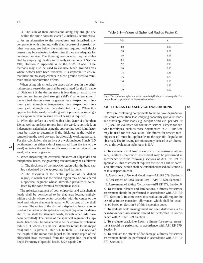
The spherical segment of both ellipsoidal and torisphericalheads shall be considered to be that area located entirelywithin a circle whose center coincides with the center of thehead and whose diameter is equal to 80 percent of the shelldiameter. The radius of the dish of torispherical heads is to beused as the radius of the spherical segment (equal to the diam-eter of the shell for standard heads, though other radii havebeen permitted). The radius of the spherical segment of ellip-soidal heads shall be considered to be the equivalent sphericalradius
K
1
D
, where
D
is the shell diameter (equal to the majoraxis) and
K
1
is given in Table 5-1. In Table 5-1,
h
is one-halfthe length of the minor axis [equal to the inside depth of theellipsoidal head measured from the tangent line (headbendline)]. For many ellipsoidal heads,
D
/2
h
equals 2.0.
5.8 FITNESS-FOR-SERVICE EVALUATIONS
Pressure containing components found to have degradationthat could affect their load carrying capability (pressure loadsand other applicable loads, e.g., weight, wind, etc., per API RP579) shall be evaluated for continued service. Fitness-for-ser-vice techniques, such as those documented in API RP 579,may be used for this evaluation. The fitness-for-service tech-niques used must be applicable to the specific degradationobserved. The following techniques may be used as an alterna-tive to the evaluation techniques in 5.7.
a. To evaluate metal loss in excess of the corrosion allow-ance, a fitness-for-service assessment may be performed inaccordance with the following sections of API RP 579, asapplicable. This assessment requires the use of a future corro-sion allowance, which shall be established based on Section 6of this inspection code.
1. Assessment of General Metal Loss—API RP 579, Section 42. Assessment of Local Metal Loss—API RP 579, Section 53. Assessment of Pitting Corrosion—API RP 579, Section 6
b. To evaluate blisters and laminations, a fitness-for-serviceassessment should be performed in accordance with API RP579, Section 7. In some cases this evaluation will require theuse of a future corrosion allowance, which shall be estab-lished based on Section 6 of this inspection code.c. To evaluate weld misalignment and shell distortions, a fit-ness-for-service assessment should be performed in accor-dance with API RP 579, Section 8.d. To evaluate crack-like flaws, a fitness-for-service assess-ment should be performed in accordance with API RP 579,Section 9.e. To evaluate the effects of fire damage, a fitness-for-serviceassessment should be performed in accordance with API RP579, Section 11.
Table 5-1—Values of Spherical Radius Factor K1
D⁄2h K1
3.0 1.36
2.8 1.27
2.6 1.18
2.4 1.08
2.2 0.99
2.0 0.90
1.8 0.81
1.6 0.73
1.4 0.65
1.2 0.57
1.0 0.50
Note: The equivalent spherical radius equals K1D; the axis ratio equals D⁄2h.Interpolation is permitted for intermediate values.
01
03
03

P
RESSURE
V
ESSEL
I
NSPECTION
C
ODE:
M
AINTENANCE
I
NSPECTION,
R
ATING
, R
EPAIR, AND
A
LTERATION
6-1
SECTION 6—INSPECTION AND TESTING OF PRESSURE VESSELS AND PRESSURE-RELIEVING DEVICES
6.1 GENERAL
Pressure vessels shall be inspected at the time of installa-tion. Internal field inspections of new vessels are not requiredas long as a manufacturer’s data report assuring that the ves-sels are satisfactory for their intended service is available. Toensure vessel integrity, all pressure vessels shall be inspectedat the frequencies provided in this section.
In selecting the technique(s) to be used for the inspection ofa pressure vessel, both the condition of the vessel and the envi-ronment in which it operates should be taken into consider-ation. The inspection, as deemed necessary by the authorizedpressure vessel inspector, may include many of a number ofnondestructive techniques, including visual inspection. Inter-nal inspection is preferred because process side degradation(corrosion, erosion, and environmental cracking) can be non-uniform throughout the vessel and, therefore, difficult to locateby external NDE. On-stream inspection may be acceptable inlieu
of internal inspection for vessels under the specific circum-stanc
es defined in 6.4. In situations where on-stream inspectionis acceptable, such inspection may be conducted either whilethe vessel is out of service and depressurized or on stream andunder pressure. Except in response to an apparent need, such aswhen environmental cracking (see
Guide for Inspection ofRefinery Equipment,
Chapter II) is suspected, inspection tech-niques exceeding the examination requirements used in thedesign and fabrication of the vessel are not required.
The appropriate inspection must provide the informationnecessary to determine that all of the essential sections or com-ponents of the vessel are safe to operate until the next scheduledinspection. The risks associated with operational shutdown andstart-up and the possibility of increased corrosion due to expo-sure of vessel surfaces to air and moisture should be evaluatedwhen an internal inspection is being planned.
6.2 RISK-BASED INSPECTION
Identifying and evaluating potential degradation mecha-nisms are important steps in an assessment of the likelihoodof a pressure vessel failure. However, adjustments to inspec-tion strategy and tactics to account for consequences of afailure should also be considered. Combining the assessmentof likelihood of failure and the consequence of failure areessential elements of risk-based inspection (RBI).
When an owner/user chooses to conduct a RBI assessment,it must include a systematic evaluation of both the likelihood offailure and the associated consequence of failure, in accordancewith API RP 580. The likelihood assessment must be based onall forms of degradation that could reasonably be expected toaffect a vessel in any particular service. Examples of those deg-radation mechanisms include: internal or external metal lossfrom an identified form of corrosion (localized or general), allforms of cracking, including hydrogen assisted and stress cor-rosion cracking (from the inside or outside surfaces of a vessel),
and any other forms of metallurgical, corrosion, or mechanicaldegradation, such as fatigue, embrittlement, creep, etc. Addi-tionally, the effectiveness of the inspection practices, tools, andtechniques utilized for finding the expected and potential degra-dation mechanisms must be evaluated. This likelihood of fail-ure assessment should be repeated each time equipment orprocess changes are made that could significantly affect degra-dation rates or cause premature failure of the vessel.
Other factors that should be considered in a RBI assess-ment conducted in accordance with API RP 580 include:appropriateness of the materials of construction; vesseldesign conditions, relative to operating conditions; appropri-ateness of the design codes and standards utilized; effective-ness of corrosion monitoring programs; and the quality ofmaintenance and inspection quality assurance/quality controlprograms. Equipment failure data and information will alsobe important information for this assessment. The conse-quence assessment must consider the potential incidents thatmay occur as a result of fluid release, including explosion,fire, toxic exposure, environmental impact, and other healtheffects associated with a failure of a vessel.
It is essential that all RBI assessments be thoroughly docu-mented in accordance with API RP 580, clearly defining all thefactors contributing to both the likelihood and consequence of afailure of the vessel.
After an effective RBI assessment is conducted, theresults can be used to establish a vessel inspection strategyand more specifically better define the following:
a. The most appropriate inspection methods, scope, tools andtechniques to be utilized based on the expected forms ofdegradation.b. The appropriate frequency for internal, external, and on-stream inspections.c. The need for pressure testing after damage has beenincurred or after repairs or modifications have been completed.d. The prevention and mitigation steps to reduce the likeli-hood and consequence of a vessel failure.
A RBI assessment may be used to establish the appropriateinspection intervals for internal and on-stream inspections,including a potential increase in the 10-year inspection limitdescribed in 6.4, as well as the external interval described in6.3. When used to increase the 10-year limit, the RBI assess-ment shall be reviewed and approved by a pressure vesselengineer and authorized pressure vessel inspector at intervalsnot to exceed 10 years, or more often if warranted by process,equipment, or consequence changes.
6.3 EXTERNAL INSPECTION
Each vessel aboveground shall be given a visual externalinspection, preferably while in operation, at least every 5years or at the same interval as the required internal or on-
98
98
03
03
98
03
03
6-2 API 510
stream inspection, whichever is less. The inspection shall, atthe least, determine the condition of the exterior insulation,the condition of the supports, the allowance for expansion,and the general alignment of the vessel on its supports. Anysigns of leakage should be investigated so that the sourcescan be established. Inspection for corrosion under insulation(CUI) shall be considered for externally-insulated vesselssubject to moisture ingress and that operate between 25°F (–4°C) and 250°F (120°C), or are in intermittent service. Thisinspection may require removal of some insulation. It is notnormally necessary to remove insulation if the entire vesselshell is always operated at a temperature sufficiently low[below 25°F (–4°C)] or sufficiently high [above 250°F(120°C)] to prevent the presence or condensation of mois-ture under the insulation. Alternatively, shell thickness mea-surements done internally at typical problem areas (forexample, stiffening rings, around nozzles, and other loca-tions which tend to trap moisture or allow moisture ingress)may be performed during internal inspections.
Buried vessels shall be inspected to determine their exter-nal environmental condition. The inspection interval shall bebased on corrosion-rate information obtained from one ormore of the following methods: (a) during maintenance activ-ity on adjacent connecting piping of similar material; (b)from the interval examination (specified in the paragraphabove) of similarly buried corrosion test coupons of similarmaterial; (c) from representative portions of the actual vessel;or (d) from a vessel in similar circumstances.
Vessels that are known to have a remaining life of over 10years or that are protected against external corrosion—forexample, (a) vessels insulated effectively to preclude theentrance of moisture, (b) jacketed cryogenic vessels, (c) ves-sels installed in a cold box in which the atmosphere is purgedwith an inert gas, and (d) vessels in which the temperaturebeing maintained is sufficiently low or sufficiently high topreclude the presence of water—do not need to have insula-tion removed for the external inspection. However, the condi-tion of their insulating system or their outer jacketing, such asthe cold box shell, shall be observed at least every 5 years andrepaired if necessary.
6.4 INTERNAL AND ON-STREAM INSPECTION
The period between internal or on-stream inspections shallnot exceed one half the estimated remaining life of the vesselbased on corrosion rate or 10 years, whichever is less. Incases where the remaining safe operating life is estimated tobe less than 4 years, the inspection interval may be the fullremaining safe operating life up to a maximum of 2 years.
For pressure vessels that are in noncontinuous service andare isolated from the process fluids such that they are notexposed to corrosive environments (such as inert gas purgedor filled with noncorrosive hydrocarbons), the 10 years shallbe the 10 years of actual service exposed life. Equipmentthat is not adequately protected from corrosive environ-ments may experience significant internal corrosion whileidle and should be carefully reviewed when setting inspec-
tion intervals. In no case should these exceed one-half theestimated remaining corrosion-rate life, or 10 years sincethe last inspection. External inspections for vessels in non-continuous service remain the same as for continuous ser-vice, as outlined in 6.3.
Except as noted below, internal inspection is normally thepreferred method of inspection and shall be conducted onvessels subject to significant localized corrosion and othertypes of damage. At the discretion of the authorized pressurevessel inspector, on-stream inspection may be substituted forinternal inspection in the following situations:
a. When size, configuration, or lack of access makes vesselentry for internal inspection physically impossible.
b. When the general corrosion rate of a vessel is known to beless than 0.005 inch (0.125 millimeter) per year and the esti-mated remaining life is greater than 10 years, and all of thefollowing conditions are met:
1. The corrosive character of the contents, including theeffect of trace components, has been established by atleast 5 years of the same or comparable service experiencewith the type of contents being handled.
2. No questionable condition is disclosed by the externalinspection specified in 6.3.
3. The operating temperature of the steel vessel shelldoes not exceed the lower temperature limits for thecreep-rupture range of the vessel material.
4. The vessel is not considered to be subject to environ-mental cracking or hydrogen damage from the fluid beinghandled. Alternatively, a RBI assessment, as permitted in6.2 can be performed to determine that the risk associatedwith environmental cracking or hydrogen damage isacceptably low and that the effectiveness of externalinspection techniques is adequate for the damage mecha-nism. This assessment should include a review of pastprocess conditions and likely future process conditions.
5. The vessel does not have a non-integrally bonded linersuch as strip lining or plate lining.
If the requirements of item b above are not met, as a resultof conditions noted during the scheduled on-stream inspec-tion, the next scheduled inspection shall be an internal inspec-tion. When a vessel has been internally inspected, the resultsof a current inspection can be used to determine whether anon-stream inspection can be substituted for an internalinspection on a similar vessel operating in the same serviceand conditions.
When an on-stream inspection is conducted in lieu of aninternal inspection, a thorough examination shall be per-formed using ultrasonic thickness measurements, or radiogra-phy, or other appropriate means of NDE to measure metalthicknesses and/or assess the integrity of the metal and welds.If an on-stream inspection is conducted, the authorized pres-sure vessel inspector shall be given sufficient access to allparts of the vessel (heads, shell, and nozzles) so that the
98
98
98
98
98
03
98
P
RESSURE
V
ESSEL
I
NSPECTION
C
ODE:
M
AINTENANCE
I
NSPECTION,
R
ATING
, R
EPAIR, AND
A
LTERATION
6-3
inspector is satisfied that an accurate assessment of the vesselcondition can be made.
A representative number of thickness measurements must beconducted on each vessel to satisfy the requirements for aninternal or on-stream inspection. For example, the thickness forall major components (shells, heads, cone sections) and a rep-resentative sample of vessel nozzles should be measured andrecorded, and the remaining life and next inspection intervalshould be calculated for the limiting component. A decision onthe number and location of the thickness measurements shouldconsider results from previous inspections, if available, and thepotential consequence of loss of containment. Measurements ata number of thickness measurement locations (TMLs) areintended to establish general and localized corrosion rates indifferent sections of the vessel. A minimal number of TMLs areacceptable when the established rate of corrosion is low andnot localized. For pressure vessels susceptible to localized cor-rosion, it is vital that those knowledgeable in localized corro-sion mechanisms be consulted about the appropriate placementand number of TMLs. Additionally, for localized corrosion, itis important that inspections are conducted using scanningmethods such as profile radiography, scanning ultrasonics, and/or other suitable NDE methods that will reveal the scope andextent of localized corrosion.
The remaining life of the vessel shall be calculated fromthe following formula:
where
t
actual
= the actual thickness, in inches (millimeters),measured at the time of inspection for a givenlocation or component.
t
required
= the required thickness, in inches (millimeters),at the same location or component as the
t
actual
measurement, computed by the design formulas(e.g., pressure and structural) before corrosionallowance and manufacturer’s tolerance areadded.
The long-term (LT) corrosion rate shall be calculated fromthe following formula:
The short-term (ST) corrosion rate shall be calculated fromthe following formula:
t
initial
= the thickness, in inches (millimeters), at the samelocation as
t
actual
measured at initial installation
or at the commencement of a new corrosion rateenvironment.
t
previous
= the thickness, in inches (millimeters), at the samelocation as
t
actual
measured during a previousinspection.
Long-term and short-term corrosion rates should be com-pared as part of the data assessment. The authorized inspec-tor, in consultation with a corrosion specialist, shall select thecorrosion rate that best reflects the current process.
A statistical analysis may be used in the corrosion rate andremaining life calculations for the pressure vessel sections.This statistical approach may be applied for assessment ofsubstituting an internal inspection (item b in the preceding),or for determining the internal inspection interval. Care mustbe taken to ensure that the statistical treatment of data resultsreflects the actual condition of the vessel section. Statisticalanalysis is not applicable to vessels with significant local-ized corrosion.
The determination of corrosion rate may include thicknessdata collected at more than two different times. Suitable useof short-term versus long-term corrosion rates shall be deter-mined by the authorized pressure vessel inspector. Whenthere is a discrepancy between short-term and long-term cor-rosion rates, a pressure vessel engineer experienced in corro-sion may need to be consulted about the use of these rates, atthe discretion of the inspector, for calculating the remaininglife and next inspection date.
For a large vessel with two or more zones of differingcorrosion rates, each zone may be treated independentlyregarding the interval between inspections or for substitut-ing the internal inspection with an on-stream inspection. If amulti-zone analysis is used, the zone with the shortestremaining half-life shall be used as the limiting case for set-ting the internal inspection interval or for substituting theinternal inspection with an on-stream inspection.
An alternative method to establish the required inspectioninterval based on remaining life is by calculation of the pro-jected maximum allowable working pressure (MAWP) ofeach vessel component as described in 5.4. This proceduremay be iterative involving selection of an inspection interval,determination of the corrosion loss expected over the interval,and calculation of the projected MAWP. The inspection inter-val is within the maximum permitted as long as the projectedMAWP of the limiting component is not less than the lowerof the name plate or rerated MAWP. The maximum inspec-tion interval using this method is also 10 years.
When problems are experienced with external loading,faulty material, or fabrication the remaining life as deter-mined above shall be reduced to recognize those conditions.If deterioration due to conditions such as those mentionedin 5.2 is detected, the inspection interval must be appropri-ately adjusted.
Remaining life (years)tactual - trequired
corrosion rate
[inches (mm) per year]
-------------------------------------------------------=
01
Corrosion rate LT( )tinitial - tactual
time (years) between tinitial and tactual------------------------------------------------------------------------------------------=
Corrosion rate ST( )tprevious - tactual
time (years) between tprevious and tactual-----------------------------------------------------------------------------------------------=
01
6-4 API 510
If the service conditions of a vessel are changed, the maxi-mum operating pressure, the maximum and minimum operat-ing temperature, and the period of operation until the nextinspection shall be established for the new service conditions.
If both the ownership and the location of a vessel arechanged, the vessel shall be internally and externallyinspected before it is reused, and the allowable conditions ofservice and the next period of inspection shall be establishedfor the new service.
6.5 PRESSURE TEST
When the authorized pressure vessel inspector believes thata pressure test is necessary or when, after certain repairs oralterations, the inspector believes that one is necessary (see7.2.9), the test shall be conducted at a pressure in accordancewith the construction code used for determining the maxi-mum allowable working pressure. To minimize the risk ofbrittle fracture during the test, the metal temperature shouldbe maintained at least 30°F (17°C) above the minimumdesign metal temperature for vessels that are more than 2inches (5 centimeters) thick, or 10°F (6°C) above for vesselsthat have a thickness of 2 inches (5 centimeters) or less. Thetest temperature need not exceed 120°F (50°C) unless there isinformation on the brittle characteristics of the vessel materialindicating that a lower test temperature is acceptable or ahigher test temperature is needed.
5
Pneumatic testing may be used when hydrostatic testing isimpracticable because of temperature, foundation, refractorylining, or process reasons; however, the potential personneland property risks of pneumatic testing shall be consideredbefore such testing is carried out. As a minimum, the inspec-tion precautions contained in the ASME Code shall beapplied in any pneumatic testing. Before applying a hydro-static test to equipment, consideration should be given to thesupporting structure and the foundation design.
When a pressure test is to be conducted in which the testpressure will exceed the set pressure of the safety relief valvewith the lowest setting, the safety relief valve or valves shouldbe removed. An alternative to removing the safety reliefvalves is to use test clamps to hold down the valve disks.Applying an additional load to the valve spring by turning thecompression screw is not recommended. Other appurte-nances, such as gauge glasses, pressure gauges, and rupturedisks, that may be incapable of withstanding the test pressureshould also be removed or should be blanked off or vented.When the pressure test has been completed, pressure reliefdevices of the proper settings and other appurtenancesremoved or made inoperable during the pressure test shall bereinstalled or reactivated.
6.6 PRESSURE-RELIEVING DEVICES
Pressure relief valves shall be tested and repaired by repairorganizations experienced in valve maintenance. Each repairorganization shall have a fully documented quality controlsystem. As a minimum, the following requirements andpieces of documentation should be included in the qualitycontrol system:
a. Title page.
b. Revision log.
c. Contents page.
d. Statement of authority and responsibility.
e. Organizational chart.
f. Scope of work.
g. Drawings and specification controls.
h. Material and part control.
i. Repair and inspection program.
j. Welding, nondestructive examination, and heat treatmentprocedures.
k. Valve testing, setting, leak testing, and sealing.
l. General example of the valve repair nameplate.
m. Procedures for calibrating measurement and test gauges.
n. Controlled copies of the manual.
o. Sample forms.
p. Repair personnel training or qualifications.
Each repair organization shall also have a fully docu-mented training program that shall ensure that repair person-nel are qualified within the scope of the repairs.
Pressure relief valves shall be tested at intervals that arefrequent enough to verify that the valves perform reliably.This may include testing pressure relief valves on newlyinstalled equipment. Pressure-relieving devices should betested and maintained in accordance with API RecommendedPractice 576. Other pressure-relieving devices, such as rup-ture disks and vacuum-breaker valves, shall be thoroughlyexamined at intervals determined on the basis of service.
The intervals between pressure-relieving-device testing orinspection should be determined by the performance of thedevices in the particular service concerned. Test or inspectionintervals on pressure-relieving devices in typical process ser-vices should not exceed 5 years, unless documented experi-ence or a risk assessment indicates that a longer interval isacceptable. For clean (nonfouling), noncorrosive services,maximum intervals may be increased to 10 years. When ser-vice records indicate that a pressure-relieving device washeavily fouled or stuck in the last inspection or test, the ser-vice interval shall be reduced if the review shows that thedevice may not perform reliably in the future. The reviewshould include an effort to determine the cause of the foulingor the reasons for the relief device not operating properly.
5
For vessels without minimum design metal temperature, the mini-mum acceptable operating temperature should be used in lieu of theminimum design metal temperature.
98
98
98
98
98
03
P
RESSURE
V
ESSEL
I
NSPECTION
C
ODE:
M
AINTENANCE
I
NSPECTION,
R
ATING
, R
EPAIR, AND
A
LTERATION
6-5
6.7 RECORDS
Pressure vessel owners and users shall maintain permanentand progressive records of their pressure vessels. Permanentrecords will be maintained throughout the service life of eachvessel; progressive records will be regularly updated toinclude new information pertinent to the operation, inspec-tion, and maintenance history of the vessel.
Pressure vessel records shall contain four types of vesselinformation pertinent to mechanical integrity as follows:
a. Construction and design information. For example,equipment serial number or other identifier, manufacturers’data reports (MDRs), design specification data, design cal-culations (where MDRs are unavailable), and constructiondrawings. For pressure vessels that have no nameplate andminimal or no design and construction documentation, thefollowing steps may be used to verify operating integrity:
i. Perform inspection to determine condition of the ves-sel. Make any necessary repairs. ii. Define design parameters and prepare drawings andcalculations.iii. Base calculations on applicable codes and standardsand condition of the vessel following any repairs. Do notuse allowable stress values based on design factor of 3.5.
See ASME Code Section VIII, Division 1, paragraphUG-10(c) for guidance on evaluation of unidentifiedmaterials. If UG-10 (c) is not followed, then for carbonsteels, use allowable stresses for SA-283 Grade C; and foralloy and nonferrous materials, use x-ray fluorescenceanalysis to determine material type on which to baseallowable stress values.
When extent of radiography originally performed is notknown, use joint factor of 0.7 for butt welds, or considerperforming radiography if a higher joint factor is required.(Recognize that performing radiography on welds in a
vessel with minimal or no design and construction docu-mentation may result in the need for a fitness-for-serviceassessment and significant repairs.)
iv. Attach a nameplate or stamping showing the maxi-mum allowable working pressure and temperature,minimum allowable temperature, and date.
v. Perform pressure test as soon as practical, as requiredby code of construction used for design calculations.
b. Operating and inspection history. For example, operatingconditions, including process upsets that may affectmechanical integrity, inspection reports, and data for eachtype of inspection conducted (for example, internal, exter-nal, thickness measurements), and inspection recommenda-tions for repair. See Appendix C for sample pressure vesselinspection records. Inspection reports shall document thedate of each inspection and/or test, the date of the nextscheduled inspection, the name of the person who performedthe inspection and/or test, the serial number or other identi-fier of the equipment inspected, a description of the inspec-tion and/or test performed, and the results of the inspectionand/or test.
c. Repair, alteration, and rerating information. For example,(1) repair and alteration forms like that shown in Appendix D,(2) reports indicating that equipment still in-service with iden-tified deficiencies or recommendations for repair are suitablefor continued service until repairs can be completed, and (3)rerating documentation (including rerating calculations, newdesign conditions, and evidence of stamping).
d. Fitness-for-service assessment documentation require-ments are described in API RP 579, Section 2.8. Specificdocumentation requirements for the type of flaw beingassessed are provided in the appropriate section of API RP579.
98
01
00
00
01

P
RESSURE
V
ESSEL
I
NSPECTION
C
ODE:
M
AINTENANCE
I
NSPECTION,
R
ATING
, R
EPAIR, AND
A
LTERATION
7-1
SECTION 7—REPAIRS, ALTERATIONS, AND RERATING OF PRESSURE VESSELS
7.1 GENERAL
This section covers repairs and alterations to pressure ves-sels by welding. The requirements that must be met beforepressure vessels can be rerated are also covered in this sec-tion. When repairs or alterations have to be performed, theapplicable requirements of the ASME Code, the codes towhich the vessels were built, or other specific pressure vesselrating codes shall be followed. Before any repairs or alter-ations are performed, all proposed methods of execution, allmaterials, and all welding procedures that are to be used mustbe approved by the authorized pressure vessel inspector and,if necessary, by a pressure vessel engineer experienced inpressure vessel design, fabrication, or inspection.
7.1.1 Authorization
All repair and alteration work must be authorized by theauthorized pressure vessel inspector before the work is startedby a repair organization (see 3.13). Authorization for alter-ations to pressure vessels that comply with Section VIII,Divisions 1 and 2, of the ASME Code and for repairs to pres-sure vessels that comply with Section VIII, Division 2, of theASME Code may not be given until a pressure vessel engi-neer experienced in pressure vessel design has been consultedabout the alterations and repairs and has approved them. Theauthorized pressure vessel inspector will designate the fabri-cation approvals that are required. The authorized pressurevessel inspector may give prior general authorization for lim-ited or routine repairs as long as the inspector is sure that therepairs are the kind that will not require pressure tests.
7.1.2 Approval
The authorized pressure vessel inspector shall approve allspecified repair and alteration work after an inspection of thework has proven the work to be satisfactory and any requiredpressure test has been witnessed.
7.1.3 Defect Repairs
A crack in a welded joint and a defect in a plate may berepaired by preparing a U- or V-shaped groove to the fulldepth and length of the crack and then filling the groove withweld metal deposited in accordance with 7.2. No crack shallbe repaired without authorization from the authorized pres-sure vessel inspector. Repairing a crack at a discontinuity,where stress concentrations may be serious, should not beattempted without prior consultation with a pressure vesselengineer experienced in pressure vessel design.
Corroded areas, as defined by 5.7, may be restored withweld metal deposited in accordance with 7.2. Surface irregu-larities and contamination shall be removed before welding.The nondestructive examination and inspection appropriate
for the extent of restoration being performed shall be speci-fied in the repair procedure.
7.2 WELDING
All repair and alteration welding shall be in accordancewith the applicable requirements of the ASME Code, exceptas permitted in 7.2.11.
7.2.1 Procedures and Qualifications
The repair organization shall use qualified welders andwelding procedures qualified in accordance with the applica-ble requirements of Section IX of the ASME Code.
7.2.2 Qualification Records
The repair organization shall maintain records of its quali-fied welding procedures and its welding performance qualifi-cations. These records shall be available to the inspector priorto the start of welding. The repair organization’s qualifiedwelding procedures and welding performance qualificationsshall be in accord with the appropriate code.
7.2.3 Preheat or Controlled Deposition Welding Methods as Alternatives to Postweld Heat Treatment
Preheat and controlled deposition welding, as described in7.2.3.1 and 7.2.3.2, may be used in lieu of postweld heat treat-ment (PWHT) where PWHT is inadvisable or mechanicallyunnecessary. Prior to using any alternative method, a metal-lurgical review conducted by a pressure vessel engineer shallbe performed to assess whether the proposed alternative issuitable for the application. The review should consider fac-tors such as the reason for the original PWHT of the equip-ment, susceptibility of the service to promote stress corrosioncracking, stresses in the location of the weld, susceptibility tohigh temperature hydrogen attack, susceptibility to creep, etc.
Selection of the welding method used shall be based on therules of the construction code applicable to the work plannedalong with technical consideration of the adequacy of theweld in the as-welded condition at operating and pressure testconditions.
When reference is made in this section to materials by theASME designation, P-Number and Group Number, therequirements of this section apply to the applicable materialsof the original code of construction, either ASME or other,which conform by chemical composition and mechanicalproperties to the ASME P-Number and Group Number desig-nations.
Vessels constructed of steels other than those listed in7.2.3.1 and 7.2.3.2 that initially required PWHT shall bepostweld heat treated if alterations or repairs involving pres-sure boundary welding are performed. When one of the fol-
00
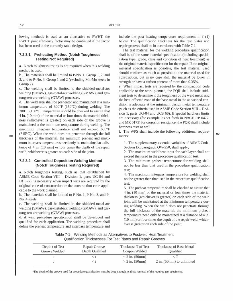
7-2 API 510
lowing methods is used as an alternative to PWHT, thePWHT joint efficiency factor may be continued if the factorhas been used in the currently rated design.
7.2.3.1 Preheating Method (Notch Toughness Testing Not Required)
a. Notch toughness testing is not required when this weldingmethod is used.b. The materials shall be limited to P-No. 1, Group 1, 2, and3, and to P-No. 3, Group 1 and 2 (excluding Mn-Mo steels inGroup 2).c. The welding shall be limited to the shielded-metal-arcwelding (SMAW), gas-metal-arc welding (GMAW), and gas-tungsten-arc welding (GTAW) processes. d. The weld area shall be preheated and maintained at a min-imum temperature of 300°F (150°C) during welding. The300°F (150°C) temperature should be checked to assure that4 in. (10 mm) of the material or four times the material thick-ness (whichever is greater) on each side of the groove ismaintained at the minimum temperature during welding. Themaximum interpass temperature shall not exceed 600°F(315°C). When the weld does not penetrate through the fullthickness of the material, the minimum preheat and maxi-mum interpass temperatures need only be maintained at a dis-tance of 4 in. (10 mm) or four times the depth of the repairweld, whichever is greater on each side of the joint.
7.2.3.2 Controlled-Deposition Welding Method (Notch Toughness Testing Required)
a. Notch toughness testing, such as that established byASME Code Section VIII – Division 1, parts UG-84 andUCS-66, is necessary when impact tests are required by theoriginal code of construction or the construction code appli-cable to the work planned.b. The materials shall be limited to P-No. 1, P-No. 3, and P-No. 4 steels.c. The welding shall be limited to the shielded-metal-arcwelding (SMAW), gas-metal-arc welding (GMAW), and gas-tungsten-arc welding (GTAW) processes.d. A weld procedure specification shall be developed andqualified for each application. The welding procedure shalldefine the preheat temperature and interpass temperature and
include the post heating temperature requirement in f (1)below. The qualification thickness for the test plates andrepair grooves shall be in accordance with Table 7-1.
The test material for the welding procedure qualificationshall be of the same material specification (including specifi-cation type, grade, class and condition of heat treatment) asthe original material specification for the repair. If the originalmaterial specification is obsolete, the test material usedshould conform as much as possible to the material used forconstruction, but in no case shall the material be lower instrength or have a carbon content of more than 0.35%.e. When impact tests are required by the construction codeapplicable to the work planned, the PQR shall include suffi-cient tests to determine if the toughness of the weld metal andthe heat-affected zone of the base metal in the as-welded con-dition is adequate at the minimum design metal temperature(such as the criteria used in ASME Code Section VIII – Divi-sion 1, parts UG-84 and UCS 66). If special hardness limitsare necessary (for example, as set forth in NACE RP 0472,and MR 0175) for corrosion resistance, the PQR shall includehardness tests as well.f. The WPS shall include the following additional require-ments:
1. The supplementary essential variables of ASME Code,Section IX, paragraph QW-250, shall apply;2. The maximum weld heat input for each layer shall notexceed that used in the procedure qualification test;3. The minimum preheat temperature for welding shallnot be less than that used in the procedure qualificationtest;4. The maximum interpass temperature for welding shallnot be greater than that used in the procedure qualificationtest;5. The preheat temperature shall be checked to assure that4 in. (10 mm) of the material or four times the materialthickness (whichever is greater) on each side of the weldjoint will be maintained at the minimum temperature dur-ing welding. When the weld does not penetrate throughthe full thickness of the material, the minimum preheattemperature need only be maintained at a distance of 4 in.(10 mm) or four times the depth of the repair weld, which-ever is greater on each side of the joint;
0000
Table 7-1—Welding Methods as Alternatives to Postweld Heat Treatment Qualification Thicknesses For Test Plates and Repair Grooves
Depth t of Test Groove Welded
a
Repair Groove Depth Qualified
Thickness T of Test Coupon Welded
Thickness of Base Metal Qualified
t < t < 2 in. (50mm) < Tt < t > 2 in. (50mm) 2 in. (50mm) to unlimited
a
The depth of the groove used for procedure qualification must be deep enough to allow removal of the required test specimens.
P
RESSURE
V
ESSEL
I
NSPECTION
C
ODE:
M
AINTENANCE
I
NSPECTION,
R
ATING
, R
EPAIR, AND
A
LTERATION
7-3
6. For the welding processes in 7.2.3.2 (c), use only elec-trodes and filler metals that are classified by the fillermetal specification with an optional supplemental diffus-ible-hydrogen designator of H8 or lower. When shieldinggases are used with a process, the gas shall exhibit a dewpoint that is no higher than –60°F (–50°C). Surfaces onwhich welding will be done shall be maintained in a drycondition during welding and free of rust, mill scale andhydrogen producing contaminants such as oil, grease andother organic materials;7. The welding technique shall be a controlled-deposi-tion, temper-bead or half-bead technique. The specifictechnique shall be used in the procedure qualification test;8. For welds made by SMAW, after completion of weld-ing and without allowing the weldment to cool below theminimum preheat temperature, the temperature of theweldment shall be raised to a temperature of 500°F ± 50°F(260°C ± 30°C) for a minimum period of two hours toassist out-gassing diffusion of any weld metal hydrogenpicked up during welding. This hydrogen bake-out treat-ment may be omitted provided the electrode used is classi-fied by the filler metal specification with an optionalsupplemental diffusible-hydrogen designator of H4 (suchas E7018-H4); and9. After the finished repair weld has cooled to ambienttemperature, the final temper bead reinforcement layershall be removed substantially flush with the surface of thebase material.
7.2.4 Nondestructive Examination of Welds
Prior to welding, the area prepared for welding shall beexamined using either the magnetic particle (MT) or the liq-uid penetrant (PT) examination method to determine that nodefects exist. After the weld is completed, it shall be exam-ined again by either of the above methods to determine thatno defects exist using acceptance standards acceptable to theInspector or code of construction most applicable to the workplanned. In addition, welds in a pressure vessel that was orig-inally required to be radiographed by the rules of the originalcode of construction, shall be radiographically examined. Insituations where it is not practical to perform radiography theaccessible surfaces of each non-radiographed repair weldshall be fully examined using the most appropriate non-destructive examination method to determine that no defectsexist, and the maximum allowable working pressure and/orallowable temperature shall be reevaluated to the satisfactionof the authorized pressure vessel inspector and jurisdiction atthe location of installation.
7.2.5 Local Postweld Heat Treatment
Note: Before local postweld heat treatment is used, a metallurgical reviewmust be conducted to determine if the vessel was postweld heat treated due tothe characteristics of the fluid contained in it.
Local postweld heat treatment (PWHT) may be substitutedfor 360-degree banding on local repairs on all materials, pro-vided that the following precautions are taken and require-ments are met:
a. The application is reviewed, and a procedure is developedby pressure vessel engineers experienced in the appropriateengineering specialties.b. The suitability of the procedure is evaluated. In evaluatingthe suitability of the procedure, the following shall be consid-ered: applicable factors, such as base metal thickness, decaythermal gradients, and material properties (hardness, constitu-ents, strength, and the like); changes due to local postweldheat treatment; the need for full penetration welds; and sur-face and volumetric examinations after local postweld heattreatment. In evaluating and developing local postweld heattreatment procedures, the overall and local strains and distor-tions resulting from the heating of a local restrained area ofthe pressure vessel shell shall be considered.c. A preheat of 300˚F (150˚C) or higher, as specified by spe-cific welding procedures, is maintained during welding.d. The required local postweld heat treatment temperatureshall be maintained for a distance of not less than two timesthe base metal thickness measured from the weld. The localpostweld heat treatment temperature shall be monitored by asuitable number of thermocouples (at least two). (Whendetermining the number of thermocouples necessary, the sizeand shape of the area being heat treated should be considered.)
Heat shall be applied to any nozzle or any attachmentwithin the local postweld heat treatment area.
7.2.6 Repairs to Stainless Steel Weld Overlay andCladding
The repair procedure(s) to restore removed, corroded, ormissing clad or overlay areas shall be reviewed and endorsedprior to implementation by the pressure vessel engineer andauthorized by the inspector.
Consideration shall be given to factors which may augmentthe repair sequence such as stress level, P number of basematerial, service environment, possible previously dissolvedhydrogen, type of lining, deterioration of base metal proper-ties (by temper embrittlement of chromium-molybdenumalloys), minimum pressurization temperatures, and a need forfuture periodic examination.
For equipment which is in hydrogen service at an elevatedtemperature or which has exposed base metal areas open tocorrosion which could result in a significant atomic hydrogenmigration in the base metal, the repair must additionally beconsidered by the pressure vessel engineer for factors affect-ing the following:
a. Outgassing base metal.b. Hardening of base metal due to welding, grinding, or arcgouging.
00
00

7-4 API 510
c. Preheat and interpass temperature control.d. Postweld heat treatment to reduce hardness and restoremechanical properties.
Repairs shall be monitored by an inspector to assure com-pliance to repair requirements. After cooling to ambient tem-peratures, the repair shall be inspected by the liquid penetrantmethod, according to ASME Code, Section VIII, Division 1,Appendix 8.
For vessels constructed with P-3, P-4, or P-5 base materi-als, the base metal in the area of repair should be examinedfor cracking by the ultrasonic examination in accordance withASME Code, Section V, Article 5, paragraph T-543. Thisinspection is most appropriately accomplished following adelay of at least 24 hours after completed repairs for equip-ment in hydrogen service and for chromium-molybdenumalloys that could be affected by delayed cracking.
7.2.7 Design
Butt joints shall have complete penetration and fusion.Parts should be replaced when repairing them is likely to beinadequate. Part replacements shall be fabricated according tothe applicable requirements of the appropriate code. Newconnections may be installed on vessels as long as the design,location, and method of attachment comply with the applica-ble requirements of the appropriate code.
Fillet-welded patches require special design consider-ations, especially relating to efficiency. Fillet-welded patchesmay be used to make temporary repairs, and the use of fillet-welded patches may be subject to the patches’ acceptance inthe jurisdiction in which they are required. Temporary repairsusing fillet-welded patches shall be approved by the autho-rized pressure vessel inspector and a pressure vessel engineercompetent in pressure vessel design; and the temporaryrepairs should be removed and replaced with suitable perma-nent repairs at the next available maintenance opportunity.Temporary repairs may remain in place for a longer period oftime only if evaluated, approved, and documented by thepressure vessel engineer and the authorized API pressure ves-sel inspector. Fillet-welded patches may be applied to theinternal or external surfaces of shells, heads, and headersas long as, in the judgment of the authorized pressure ves-sel inspector, either of the following is true:
a. The fillet-welded patches provide design safety equivalentto reinforced openings designed according to the applicablesection of the ASME Code.b. The fillet-welded patches are designed to absorb the mem-brane strain of the parts so that in accordance with the rules ofthe applicable section of the ASME Code, the followingresult:
1. The allowable membrane stress is not exceeded in thevessel parts or the patches.2. The strain in the patches does not result in fillet-weldstresses that exceed allowable stresses for such welds.
Overlay patches shall have rounded corners. Flush (insert)patches shall also have rounded corners, and they shall beinstalled with full-penetration butt joints.
Refer to API Publication 2201 when making on-streamrepairs.
A full encirclement lap band repair may be considered along term repair if the design is approved, and documented bythe pressure vessel engineer and the authorized API pressurevessel inspector and the following requirements are met:
a. The repair is not being made to a crack in the vessel shell.
b. The band alone is designed to contain the full design pres-sure.
c. All longitudinal seams in the repair band are full penetra-tion butt welds with the design joint efficiency and inspectionconsistent with the appropriate code.
d. The circumferential fillet welds attaching the band to thevessel shell are designed to transfer the full longitudinal loadin the vessel shell, using a joint efficiency of 0.45, withoutcounting on the integrity of the original shell material coveredby the band. Where significant, the eccentricity effects of theband relative to the original shell shall be considered in sizingthe band attachment welds. Other than visual examination,fillet weld examination may be done at the next shutdown ifconditions and necessary access do not permit completeexamination at the time of an on-stream repair.
e. Fatigue of the attachment welds, such as fatigue resultingfrom differential expansion of the band relative to the vesselshell, should be considered if applicable.
f. The band material and weld metal are suitable for contactwith the contained fluid at the design conditions and anappropriate corrosion allowance is provided in the band.
g. The degradation mechanism leading to the need for repairshall be considered in determining the need for any additionalmonitoring and future inspection of the repair.
Non-penetrating nozzles (including pipe caps attached asnozzles) may be used as long term repairs for other thancracks when the design and method of attachment complywith the applicable requirements of the appropriate code. Thedesign and reinforcement of such nozzles shall consider theloss of the original shell material enclosed by the nozzle. Thenozzle material shall be suitable for contact with the con-tained fluid at the design conditions and an appropriate corro-sion allowance shall be provided. The degradationmechanism leading to the need for repair shall be consideredin determining the need for any additional monitoring andfuture inspection of the repair.
For the purposes of future inspection, it may be necessaryto consider repair bands and non-penetrating nozzles to beseparate zones when addressing the on-stream inspectionrequirements in 6.4.
00
00
P
RESSURE
V
ESSEL
I
NSPECTION
C
ODE:
M
AINTENANCE
I
NSPECTION,
R
ATING
, R
EPAIR, AND
A
LTERATION
7-5
7.2.8 Material
The material used in making repairs or alterations shallconform to the applicable section of the ASME Code. Thematerial shall be of known weldable quality and be compati-ble with the original material. Carbon or alloy steel with acarbon content over 0.35 percent shall not be welded.
7.2.9 Inspection
Acceptance criteria for a welded repair or alteration shouldinclude nondestructive examination techniques that are inaccordance with the applicable sections of the ASME Code oranother applicable vessel rating code. Where use of thesenondestructive examination techniques is not possible orpractical, alternative nondestructive examination methodsmay be used provided they are approved by the pressure ves-sel engineer and the authorized pressure vessel inspector.
For vessels constructed of materials that may be subject tobrittle fracture (per API RP 579, or other analysis) from eithernormal or abnormal service (including start-up, shutdown,and pressure testing), appropriate inspection should be con-sidered after welded repairs or alterations. Flaws, notches, orother stress risers could initiate a brittle fracture in subsequentpressure testing or service. Magnetic particle testing andother effective surface NDE methods should be considered.Inspection techniques should be designed to detect criticalflaws as determined by a fitness-for-service assessment.
7.2.10 Testing
After repairs are completed, a pressure test shall be appliedif the authorized pressure vessel inspector believes that one isnecessary. The pressure test should be in accordance with thedesign rules of construction for the vessel. For vessels thathave been designed or rerated using the design allowablestress published in the 1999 addendum of Section VIII of theASME code, Code Case 2290, or Code Case 2278, 130% ofMAWP is the appropriate minimum pressure test. For vesselsdesigned or rerated using the design allowable stress pub-lished prior to the 1999 addendum, 150% of MAWP is nor-mally the appropriate minimum pressure test. The testpressure should be corrected for temperature as follows:
Test Pressure = 1.3 MAWP
x
(
S
test temp
/
S
design temp
),
where
S
test temp
= allowable stress at test temperature
S
design temp
= allowable stress at design temperature
For vessels that are susceptible to chloride stress corrosioncracking, such as those constructed of austenitic stainlesssteels, attention should be paid to the chloride content of thetesting water, and to making sure that complete draining anddrying procedures are in effect.
A pressure test is normally required after an alteration.Subject to the approval of the jurisdiction (where the jurisdic-tion’s approval is required), appropriate nondestructive exam-
inations shall be required where a pressure test is notperformed. Substituting nondestructive examination proce-dures for a pressure test after an alteration may be done onlyafter a pressure vessel engineer experienced in pressure ves-sel design and the authorized pressure vessel inspector havebeen consulted.
For cases where UT is substituted for radiographicinspection, the owner/user shall specify industry-qualifiedUT shear wave examiners for closure welds that have notbeen pressure tested and for weld repairs identified by thepressure vessel engineer or authorized inspector. Therequirement for use of industry-qualified UT shear waveexaminers becomes effective two years after publication inthis code or addendum.
7.2.11 Filler Metal
The filler metal used for weld repairs should have minimumspecified tensile strength equal to or greater than the minimumspecified tensile strength of the base metal. If a filler metal isused that has a minimum specified tensile strength lower thanthe minimum specified tensile strength of the base metal, thecompatibility of the filler metal chemistry with the base metalchemistry shall be considered regarding weldability and ser-vice degradation. In addition, the following shall be met:
a. The repair thickness shall not be more than 50 percent of therequired base metal thickness, excluding corrosion allowance.
b. The thickness of the repair weld shall be increased by a ratioof minimum specified tensile strength of the base metal andminimum specified tensile of the filler metal used for the repair.
c. The increased thickness of the repair shall have roundedcorners and shall be blended into the base metal using a 3-to-1taper.
d. The repair shall be made with a minimum of two passes.
7.3 RERATING
Rerating a pressure vessel by changing its temperature rat-ings or its maximum allowable working pressure may be doneonly after all of the following requirements have been met:
a. Calculations from either the manufacturer or an owner-userpressure vessel engineer (or his designated representative)experienced in pressure vessel design, fabrication, or inspec-tion shall justify rerating.
b. A rerating shall be established in accordance with therequirements of the construction code to which the pressurevessel was built or by computations that are determined usingthe appropriate formulas in the latest edition of the ASMECode if all of the essential details comply with the applicablerequirements of the code being used. If the vessel wasdesigned to an edition or addendum of the ASME Code ear-lier than the 1999 Addenda and was not designed to CodeCase 2290 or 2278, it may be rerated to the latest edition/addendum of the ASME Code if permitted by Figure 7-1.
01
03
01
00
7-6 API 510
c. Current inspection records verify that the pressure vesselis satisfactory for the proposed service conditions and that thecorrosion allowance provided is appropriate. An increase inallowable working pressure or temperature shall be based onthickness data obtained from a recent internal or on-streaminspection.
d. If the pressure vessel has at some time been pressure testedto a test pressure equal to or higher than the pressure test pres-sure required by the latest edition or addendum of the ASMECode, or the vessel integrity is maintained by special nonde-structive evaluation inspection techniques in lieu of testing, apressure test for the rerated condition is not required.
e. The pressure vessel inspection and rerating is acceptableto the authorized pressure vessel inspector.
The pressure vessel rerating will be considered completewhen the authorized pressure vessel inspector oversees theattachment of an additional nameplate or additional stampingthat carries the following information:
00
Rerated byMaximum Allowable Working Pressure psi at F°Date

P
RESSURE
V
ESSEL
I
NSPECTION
C
ODE:
M
AINTENANCE
I
NSPECTION,
R
ATING
, R
EPAIR, AND
A
LTERATION
7-7
Figure 7-1—Rerating Vessels Using the Latest Edition or Addendum of the ASME Code Allowable Stresses
Obtain original vessel data.
Was vessel built to 1968 or later
edition of ASME Code (see note 1)?
Are vessel materials listed in the
latest edition/addendum of the ASME Code
(see note 2)?
Is allowable stress at rerate
temperature per the latest edition/addendum of the ASME
Code higher than original allowable
stress?
Was the vessel material
specification replaced by a current specification?
Was the vessel material
originally certified using UG10 of ASME
code?
Can the vessel material be
certified using UG10 of ASME code?
Can the vessel material
properties meet a current material specification?
Has the material been
degraded due to operation (see note 3)?
Does the material
toughness meet the latest edition/addendum of the ASME Code toughness
requirements?
Do the vessel components satisfy
the impact toughness requirement in RP 579, Sec. 3, or other recognized FFS standards
for the rerated condition?
Review operational history.
Vessel or components cannot be rerated using the latest
edition/addendum of the ASME Code allowable stress.
Rerate vessel or component using the latest
edition/addendum of the ASME Code allowable stress.
No incentive to use thelatest edition/addendum of the ASME Code allowable
stress for rerating.
Notes:
1. ASME Code identified as ASME Section VIII, Div. 1.
2. Vessel material(s) are defined as material essential to the structural integrity of the vessel.
3. Material degradation due to operation is defined as loss of material strength, ductility, or toughness due to creep, graphitization, temper embrittlement, hydrogen attack, fatigue, etc., see API RP 579.
No
No
No No
No
No
No
No
No
No
Yes
Yes
Yes
Yes
Yes
Yes
Yes
Yes
Yes
Yes
00


P
RESSURE
V
ESSEL
I
NSPECTION
C
ODE:
M
AINTENANCE
I
NSPECTION,
R
ATING
, R
EPAIR, AND
A
LTERATION
8-1
SECTION 8—ALTERNATIVE RULES FOR EXPLORATION ANDPRODUCTION PRESSURE VESSELS
8.1 SCOPE AND SPECIFIC EXEMPTIONS
This section sets forth the minimum alternative inspectionrules for pressure vessels that are exempt from the rules setforth in Section 6 except as referenced in paragraphs 8.4 and8.5. Except for Section 6, all of the sections in this inspectioncode are applicable to Exploration and Production (E&P)pressure vessels. These rules are provided because of thevastly different characteristics and needs of pressure vesselsused for E&P service. Typical E&P services are vessels asso-ciated with drilling, production, gathering, transportation, andtreatment of liquid petroleum, natural gas, natural gas liquids,and associated salt water (brine).
The following are specific exemptions:
a. Portable pressure vessels and portable compressed gascontainers associated with construction machinery, pile driv-ers, drilling rigs, well-servicing rigs and equipment, compres-sors, trucks, ships, boats, and barges shall be treated, forinspection and recording purposes, as a part of that machineryand shall be subject to prevailing rules and regulations appli-cable to that specific type of machine or container.b. Pressure vessels referenced in Appendix A are exemptfrom the specific requirements of this inspection code.
8.2 GLOSSARY OF TERMS
8.2.1 class of vessels:
Pressure vessels used in a com-mon circumstance of service, pressure, and risk.
8.2.2 inspection:
The external, internal, or on-streamevaluation (or any combination of the three) of a pressure ves-sel’s condition.
a.
external inspection:
Evaluation performed from theoutside of a pressure vessel using visual procedures to estab-lish the suitability of the vessel for continued operation. Theinspection may, or may not, be carried out while the vessel isin operation.b.
internal inspection:
Evaluation performed from theinside of a pressure vessel using visual and/or nondestructiveexamination procedures to establish the suitability of the ves-sel for continued operation.
c.
on-stream inspection:
Evaluation performed from theoutside of a pressure vessel using nondestructive examinationprocedures to establish the suitability of the vessel for contin-ued operation. The vessel may, or may not, be in operationwhile the inspection is carried out.
d.
progressive inspection:
An inspection whose scope(coverage, interval, technique, and so forth) is increased as aresult of inspection findings.
8.2.3 Section 8 vessel:
A pressure vessel which isexempted from the rules set forth in Section 6 of this document.
8.3 INSPECTION PROGRAM
Each owner or user of Section 8 vessels shall have aninspection program that will assure that the vessels have suffi-cient integrity for the intended service. Each E&P owner oruser shall have the option of employing, within the limitationsof the jurisdiction in which the vessels are located, any appro-priate engineering, inspection, classification, and recordingsystems which meet the requirements of this document.
8.3.1 On-Stream or Internal Inspections
a. Either an on-stream inspection or an internal inspectionmay be used interchangeably to satisfy inspection require-ments. An internal inspection is required when the vesselintegrity cannot be established with an on-stream inspection.When an on-stream inspection is used, a progressive inspec-tion shall be employed.b. In selecting the technique(s) to be utilized for the inspec-tion of a pressure vessel, both the condition of the vessel andthe environment in which it operates should be taken intoconsideration. The inspection may include any number ofnondestructive techniques, including visual inspection, asdeemed necessary by the owner-user. c. At each on-stream or internal inspection, the remainingcorrosion-rate life shall be determined as described in 8.3.2.
8.3.2 Remaining Corrosion Rate Life Determination
For a new vessel, a vessel for which service conditions arebeing changed, or existing vessels, the remaining corrosionrate life shall be determined for each vessel or estimated for aclass of vessels based on the following formula:
where
t
actual
= the actual thickness, in inches (millimeters),measured at the time of inspection for a givenlocation or component.
t
required
= the required thickness, in inches (millime-ters), at the same location or component asthe t
actual
measurement, obtained by one of thefollowing methods:
a. The nominal thickness in the uncorroded condition, lessthe specified corrosion allowance.
Remaining life (years)tactual — trequired
corrosion rate
[inches (mm) per year]
-------------------------------------------------------=
01
8-2 API 510
b. The original measured thickness, if documented, in theuncorroded condition, less the specified corrosion allowance.c. Calculations in accordance with the requirements of theconstruction code to which the pressure vessel was built, orby computations that are determined using the appropriateformulas in the latest edition of the ASME Code, if all of theessential details comply with the applicable requirements ofthe code being used.
corrosion rate = loss of metal thickness, in inches (milli-meters), per year. For vessels in which thecorrosion rate is unknown, the corrosion rateshall be determined by one of the followingmethods:
1. A corrosion rate may be calculated from data col-lected by the owner or user on vessels in the same or sim-ilar service.2. If data on vessels providing the same or similar serviceis not available, a corrosion rate may be estimated fromthe owner’s or user’s experience or from published data onvessels providing comparable service.3. If the probable corrosion rate cannot be determined byeither item a or item b above, on-stream determinationshall be made after approximately 1000 hours of serviceby using suitable corrosion monitoring devices or actualnondestructive thickness measurements of the vessel orsystem. Subsequent determinations shall be made afterappropriate intervals until the corrosion rate is established.
The remaining life shall be determined by an individualexperienced in pressure vessel design and/or inspection. If it isdetermined that an inaccurate assumption has been made foreither corrosion rate or thickness, the remaining life shall beincreased or decreased to agree with the actual rate or thickness.
Other failure mechanisms (stress corrosion, brittle fracture,blistering, and so forth,) shall be taken into account in deter-mining the remaining life of the vessel.
8.3.3 External Inspections
The following apply to external inspections:
a. The external visual inspection shall, at least, determine thecondition of the shell, heads, nozzles, exterior insulation, sup-ports and structural parts, pressure-relieving devices, allow-ance for expansion, and general alignment of the vessel on itssupports. Any signs of leakage should be investigated so thatthe sources can be established. It is not necessary to removeinsulation if the entire vessel shell is maintained at a tempera-ture sufficiently low or sufficiently high to prevent the con-densation of moisture. Refer to API Recommended Practice572 for guidelines on external vessel inspections. b. Buried sections of vessels shall be monitored to determinetheir external environmental condition. This monitoring shallbe done at intervals that shall be established based on corro-sion-rate information obtained during maintenance activity
on adjacent connected piping of similar material, informationfrom the interval examination of similarly buried corrosiontest coupons of similar material, information from representa-tive portions of the actual vessel, or information from a sam-ple vessel in similar circumstances.c. Vessels that are known to have a remaining life of over 10years or that are protected against external corrosion—forexample, (1) vessels insulated effectively to preclude theentrance of moisture, (2) jacketed cryogenic vessels, (3) ves-sels installed in a cold box in which the atmosphere is purgedwith an inert gas, and (4) vessels in which the temperaturebeing maintained is sufficiently low or sufficiently high topreclude the presence of water—do not need to have insula-tion removed for the external inspection; however, the condi-tion of their insulating system or their outer jacketing, such asthe cold box shell, shall be observed at least every 5 years andrepaired if necessary.
8.3.4 Vessel Classifications
The pressure vessel owner or user shall have the option toestablish vessel inspection classes by grouping vessels intocommon classes of service, pressure, and/or risk. Vessel clas-sifications shall be determined by an individual(s) experi-enced in the criteria outlined in the following. If vessels aregrouped into classes (such as lower and/or higher risk), at aminimum, the following shall be considered to establish therisk class:
a. Potential for vessel failure, such as, minimum designmetal temperature; potential for cracking, corrosion, and ero-sion; and the existence of mitigation factors.b. Vessel history, design, and operating conditions, such as,the type and history of repairs or alterations, age of vessel,remaining corrosion allowance, properties of contained fluids,operating pressure, and temperature relative to design limits.c. Consequences of vessel failure, such as, location of vesselrelative to employees or the public, potential for equipmentdamage, and environmental consequences.
8.3.5 Inspection Intervals
The following apply to inspection intervals:
a. Inspections shall be performed at intervals determined bythe vessel’s risk classification. The inspection intervals for thetwo main risk classifications (lower and higher) are definedbelow. When additional classes are established, inspectionand sampling intervals shall be set between the higher riskand lower risk classes as determined by the owner or user. Ifthe owner or user decides to not classify vessels into riskclasses, the inspection requirements and intervals of higher-risk vessels shall be followed. b. Lower-risk vessels shall be inspected as follows:
1. Inspections on a representative sample of vessels inthat class, or all vessels in that class, may be performed.
P
RESSURE
V
ESSEL
I
NSPECTION
C
ODE:
M
AINTENANCE
I
NSPECTION,
R
ATING
, R
EPAIR, AND
A
LTERATION
8-3
2. External inspections shall be performed when an on-stream or internal inspection is performed or at shorterintervals at the owner or user’s option.3. On-stream or internal inspections shall be performed atleast every 15 years or
3
⁄
4
-remaining corrosion-rate life,whichever is less.4. Any signs of leakage or deterioration detected in theinterval between inspections shall require an on-stream orinternal inspection of that vessel and a reevaluation of theinspection interval for that vessel class.
c. Higher-risk vessels shall be inspected as follows:1. External inspections shall be performed when an on-stream or internal inspection is performed or at shorterintervals at the owner or user’s option.2. On-stream or internal inspections shall be performed atleast every 10 years or
1
⁄
2
-remaining corrosion rate life,which ever is less. 3. In cases where the remaining life is estimated to be lessthan 4 years, the inspection interval may be the fullremaining life up to a maximum of 2 years. Considerationshould also be given to increasing the number of vesselsinspected within that class to improve the likelihood ofdetecting the worst-case corrosion.4. Any signs of leakage or deterioration detected in theinterval between inspections shall require an on-stream orinternal inspection of that vessel and a reevaluation of theinspection interval for that vessel class.
d. Pressure vessels (whether grouped into classes or not)shall be inspected at intervals sufficient to insure their fitnessfor continued service. Operational conditions and vesselintegrity may require inspections at shorter intervals than theintervals stated above.e. If service conditions change, the maximum operatingtemperature, pressure, and interval between inspections mustbe reevaluated.f. For large vessels with two or more zones of differing cor-rosion rates, each zone may be treated independently regard-ing the interval between inspections.
8.3.6 Additional Inspection Requirements
Additional inspection requirements, regardless of vesselclassification, exist for the following vessels:
a. Vessels that have changed ownership and location musthave an on-stream or internal inspection performed to estab-
lish the next inspection interval and to assure that the vessel issuitable for its intended service. Inspection of new vessels isnot required if a manufacturer’s data report is available. b. If a vessel is transferred to a new location, and it has beenmore than 5 years since the vessel’s last inspection, an on-stream or internal inspection is required. (Vessels in truck-mounted, skid-mounted, ship-mounted, or barge-mountedequipment are not included.)c. Air receivers (other than portable equipment) shall beinspected at least every 5 years. d. Portable or temporary pressure vessels that are employedfor the purpose of testing oil and gas wells during completionor recompletion shall be inspected at least once during each3-year period of use. More frequent inspections shall be con-ducted if vessels have been in severe corrosive environments.
8.4 PRESSURE TEST
When a pressure test is conducted, the test shall be inaccordance with the procedures in 6.5.
8.5 SAFETY RELIEF DEVICES
Safety relief devices shall be inspected, tested, and repairedin accordance with 6.6.
8.6 RECORDS
The following records requirements apply:
a. Pressure vessel owners and users shall maintain pressurevessel records. The preferred method of record keeping is tomaintain data by individual vessel. Where vessels are groupedinto classes, data may be maintained by vessel class. Wheninspections, repairs, or alterations are made on an individualvessel, specific data shall be recorded for that vessel.b. Examples of information that may be maintained are ves-sel identification numbers; safety relief device information;and the forms on which results of inspections, repairs, alter-ations, or reratings are to be recorded. Any appropriateforms may be used to record these results. A sample pressurevessel inspection record is shown in Appendix C. A samplealteration or rerating of pressure vessel form is shown inAppendix D. Information on maintenance activities andevents that affect vessel integrity should be included in thevessel records.
98
98

A-1
APPENDIX A—ASME CODE EXEMPTIONS
The following classes of containers and pressure vesselsare excluded from the specific requirements of this inspec-tion code:
a. Pressure vessels on movable structures covered by juris-dictional regulations:
1. Cargo or volume tanks for trucks, ships, and barges.2. Air receivers associated with braking systems ofmobile equipment.3. Pressure vessels installed in ocean-going ships, barges,and floating craft.
b. All classes of containers listed for exemption from thescope of Section VIII, Division 1, of the ASME Code:
1. Those classes of containers within the scope of othersections of the ASME Code other than Section VIII.2. Fired process tubular heaters.3. Pressure containers that are integral parts or compo-nents of rotating or reciprocating mechanical devices, suchas pumps, compressors, turbines, generators, engines, andhydraulic or pneumatic cylinders where the primary designconsiderations or stresses are derived from the functionalrequirements of the device.4. Any structure whose primary function is transportingfluids from one location to another within a system ofwhich it is an integral part (that is, piping systems).5. Piping components such as pipe, flanges, bolting, gaskets,valves, expansion joints, fittings, and the pressure-containingparts of other components such as strainers and deviceswhich serve such purposes as mixing, separating, snub-bing, distributing, and metering or controlling flow as longas the pressure-containing parts of these components are
generally recognized as piping components or accesso-ries.6. A vessel for containing water under pressure, includingvessels containing air, the compression of which servesonly as a cushion, when the following limitations are notexceeded:
(a) A design pressure of 300 pounds per square inch(2067.7 kilopascals).(b) A design temperature of 210˚F (99˚C).
7. A hot water supply storage tank heated by steam or anyother indirect means when the following limitations arenot exceeded:
(a) A heat input of 200,000 British thermal units (211
×
108 joules) per hour.(b) A water temperature of 210˚F (99˚C).(c) A nominal water-containing capacity of 120 gallons(455 liters).
8. Vessels with an internal or external operating pressurenot exceeding 15 pounds per square inch (103.4 kilopas-cals) but with no limitation on size.9. Vessels with an inside diameter, width, height, or cross-section diagonal not exceeding 6 inches (15 centimeters)but with no limitation on their length or pressure.10. Pressure vessels for human occupancy.
c. Pressure vessels that do not exceed the following volumesand pressures:
1. Five cubic feet (0.141 cubic meters) in volume and 250pounds per square inch (1723.1 kilopascals) design pressure.2. One-and-one-half cubic feet (0.042 cubic meters) involume and 600 pounds per square inch (4136.9 kilopas-cals) design pressure.

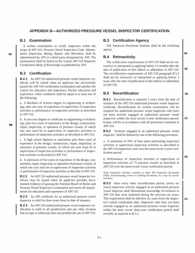
B-1
APPENDIX B—AUTHORIZED PRESSURE VESSEL INSPECTOR CERTIFICATION
B.1 Examination
A written examination to certify inspectors within thescope of API 510,
Pressure Vessel Inspection Code: Mainte-nance Inspection, Rating, Repair, and Alteration,
shall beadministered by API or a third party designated by API. Theexamination shall be based on the current
API 510
InspectorCertification Body of Knowledge
as published by API.
B.2 Certification
B.2.1
An API 510 authorized pressure vessel inspector cer-tificate will be issued when an applicant has successfullypassed the API 510 certification examination and satisfies thecriteria for education and experience. His/her education andexperience, when combined, shall be equal to at least one ofthe following:
a. A Bachelor of Science degree in engineering or technol-ogy, plus one year of experience in supervision of inspectionactivities or performance of inspection activities as describedin API 510.
b. A two-year degree or certificate in engineering or technol-ogy, plus two years of experience in the design, construction,repair, inspection, or operation of pressure vessels, of whichone year must be in supervision of inspection activities orperformance of inspection activities as described in API 510.
c. A high school diploma or equivalent, plus three years ofexperience in the design, construction, repair, inspection, oroperation of pressure vessels, of which one year must be insupervision of inspection activities or performance of inspec-tion activities as described in API 510.
d. A minimum of five years of experience in the design, con-struction, repair, inspection, or operation of pressure vessels, ofwhich one year must be in supervision of inspection activitiesor performance of inspection activities as describe in API 510.
B.2.2
An API 510 authorized pressure vessel inspector cer-tificate may be issued when an applicant provides docu-mented evidence of passing the National Board of Boiler andPressure Vessel Inspectors examination and meets all require-ments for education and experience of API 510.
B.2.3
An API certificate for an authorized pressure vesselinspector is valid for three years from its date of issuance.
B.2.4
An API 510 authorized pressure vessel inspector cer-tification is valid in all jurisdictions and any other locationthat accepts or otherwise does not prohibit the use of API 510.
B.3 Certification Agency
The American Petroleum Institute shall be the certifyingagency.
B.4 Retroactivity
The certification requirements of API 510 shall not be ret-roactive or interpreted as applying before 12 months after thedate of publication of this edition or addendum of API 510.The recertification requirements of API 510 paragraph B.5.2shall not be retroactive or interpreted as applying before 3years after the date of publication of this edition or addendumof API 510.
B.5 Recertification
B.5.1
Recertification is required 3 years from the date ofissuance of the API 510 authorized pressure vessel inspectorcertificate. Recertification by written examination will berequired for authorized pressure vessel inspectors who havenot been actively engaged as authorized pressure vesselinspectors within the most recent 3-year certification period.Exams will be in accordance with all provisions contained inAPI 510.
B.5.2
“Actively engaged as an authorized pressure vesselinspector” shall be defined by one of the following provisions:
a. A minimum of 20% of time spent performing inspectionactivities or supervision inspection activities as described inthe API 510 inspection code over the most recent 3-year certi-fication period.
b. Performance of inspection activities or supervision ofinspection activities on 75 pressure vessels as described inAPI 510 over the most recent 3-year certification period.
Note: Inspection activities common to other API inspection documents(NDE, record-keeping, review of welding documents, etc.) may be consid-ered here.
B.5.3
Once every other recertification period, (every sixyears) inspectors actively engaged as an authorized pressurevessel inspector shall demonstrate knowledge of revisions toAPI 510 that were instituted during the previous six years.This requirement shall be effective six years from the inspec-tor’s initial certification date. Inspectors who have not beenactively engaged as an authorized pressure vessel inspectorwithin the most recent three-year certification period shallrecertify as required in B.5.1.
98
9898
98
98
98
98
03
03

C-1
APPENDIX C—SAMPLE PRESSURE VESSEL INSPECTION RECORD

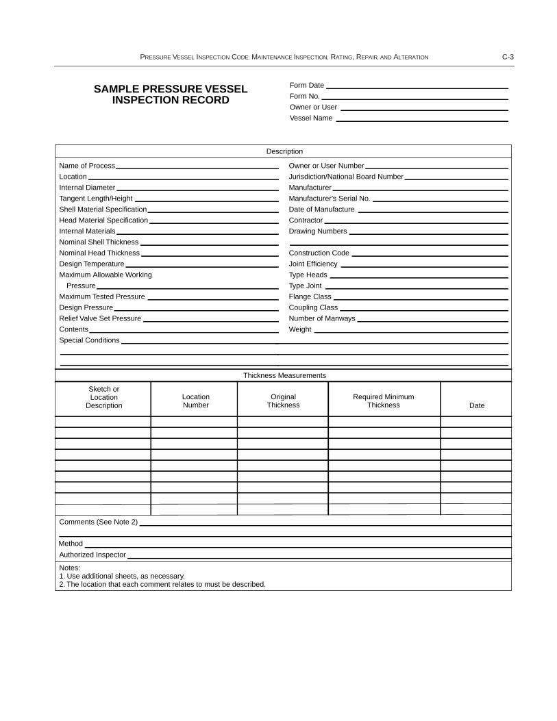
P
RESSURE
V
ESSEL
I
NSPECTION
C
ODE:
M
AINTENANCE
I
NSPECTION,
R
ATING
, R
EPAIR, AND
A
LTERATION
C-3
SAMPLE PRESSURE VESSELINSPECTION RECORD
Form Date
Form No.
Owner or User
Vessel Name
Name of Process
Description
Location
Internal Diameter
Tangent Length/Height
Shell Material Specification
Head Material Specification
Internal Materials
Nominal Shell Thickness
Nominal Head Thickness
Design Temperature
Maximum Allowable Working
Pressure
Maximum Tested Pressure
Design Pressure
Relief Valve Set Pressure
Contents
Special Conditions
Comments (See Note 2)
Authorized Inspector
Notes:1. Use additional sheets, as necessary.2. The location that each comment relates to must be described.
Method
Owner or User Number
Jurisdiction/National Board Number
Manufacturer
Manufacturer’s Serial No.
Date of Manufacture
Contractor
Drawing Numbers
Construction Code
Joint Efficiency
Type Heads
Type Joint
Flange Class
Coupling Class
Number of Manways
Weight
Thickness Measurements
Sketch orLocation
DescriptionLocationNumber
OriginalThickness
Required MinimumThickness Date


D-1
APPENDIX D—SAMPLE REPAIR, ALTERATION, OR RERATINGOF PRESSURE VESSEL FORM


P
RESSURE
V
ESSEL
I
NSPECTION
C
ODE:
M
AINTENANCE
I
NSPECTION,
R
ATING
, R
EPAIR, AND
A
LTERATION
D-3
SAMPLE REPAIR ALTERATION OR RERATING OF PRESSURE VESSEL FORM
Owner or User NameVessel Name
Serial No.
Year Built
Year BuiltAt Pressure
Head Material
Head Thickness
At Pressure
Fluid Position
Form DateForm No.
1. Original Vessel Identification Number 2. Original Vessel Location3. Manufacturer
4. See attachments for additional data? ❏ Yes ❏ No 5. Original Construction Code6. Original Maximum Allowable Working Pressure7. Original Design Temperature8. Original Minimum Design Metal Temperature9. Original Test Pressure10. Shell Material
11. Shell Thickness12. Original Joint Efficiency13. Original Radiography ❏ Yes ❏ No
❏ Yes ❏ No
❏ radiographic ❏ ultrasonic❏ magnetic particle ❏ penetrant
❏ visual ❏ other
❏ Yes ❏ No
❏ Repair ❏ Alteration ❏ Rerating
14. Original PWHTIf yes, Temp (°F) Time (Hrs)
Temp (°F) Time (Hrs)
15. Original Corrosion Allowance16. Work on Vessel Classified as:17. Organization Performing Work18. Construction Code for Present Work19. New Vessel Identification Number (if Applicable)20. New Vessel Location (if Applicable)21. New Maximum Allowable Working Pressure22. New Design Temperature23. New Minimum Design Metal Temperature24. New PWHT
25. New Joint Efficiency, if Applicable E =26. Type of Examination or Inspection Performed:
27. New Pressure Test if Yes, Pressure Test Medium Test Position28. New Corrosion Allowance29. Describe work performed (attach drawings, calculations, and other pertinent data):
I, the undersigned, an inspector employed by , having inspected the work described above, statethat to the best of my knowledge, the work has been satisfactorily completed in accordance with the Edition of API 510,Pressure Vessel Inspection Code.
Statement of Compliance
(repair, alteration, or rerating organization)
(authorized representative)Signed
Date
We certify that the statements made in this report are correct and that all material and construction for and workmanship of this❏ repair ❏ alteration, ❏ rerating conform to the requirements of the Edition of API 510, Pressure Vessel Inspection Code.
Statement of Inspection
Signed
API 510 Certification NumberDate

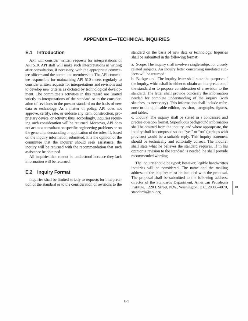
E-1
APPENDIX E—TECHNICAL INQUIRIES
E.1 Introduction
API will consider written requests for interpretations ofAPI 510. API staff will make such interpretations in writingafter consultation, if necessary, with the appropriate commit-tee officers and the committee membership. The API commit-tee responsible for maintaining API 510 meets regularly toconsider written requests for interpretations and revisions andto develop new criteria as dictated by technological develop-ment. The committee’s activities in this regard are limitedstrictly to interpretations of the standard or to the consider-ation of revisions to the present standard on the basis of newdata or technology. As a matter of policy, API does notapprove, certify, rate, or endorse any item, construction, pro-prietary device, or activity; thus, accordingly, inquiries requir-ing such consideration will be returned. Moreover, API doesnot act as a consultant on specific engineering problems or onthe general understanding or application of the rules. If, basedon the inquiry information submitted, it is the opinion of thecommittee that the inquirer should seek assistance, theinquiry will be returned with the recommendation that suchassistance be obtained.
All inquiries that cannot be understood because they lackinformation will be returned.
E.2 Inquiry Format
Inquiries shall be limited strictly to requests for interpreta-tion of the standard or to the consideration of revisions to the
standard on the basis of new data or technology. Inquiriesshall be submitted in the following format:
a. Scope. The inquiry shall involve a single subject or closelyrelated subjects. An inquiry letter concerning unrelated sub-jects will be returned.b. Background. The inquiry letter shall state the purpose ofthe inquiry, which shall be either to obtain an interpretation ofthe standard or to propose consideration of a revision to thestandard. The letter shall provide concisely the informationneeded for complete understanding of the inquiry (withsketches, as necessary). This information shall include refer-ence to the applicable edition, revision, paragraphs, figures,and tables.c. Inquiry. The inquiry shall be stated in a condensed andprecise question format. Superfluous background informationshall be omitted from the inquiry, and where appropriate, theinquiry shall be composed so that “yes” or “no” (perhaps withprovisos) would be a suitable reply. This inquiry statementshould be technically and editorially correct. The inquirershall state what he believes the standard requires. If in hisopinion a revision to the standard is needed, he shall providerecommended wording.
The inquiry should be typed; however, legible handwritteninquiries will be considered. The name and the mailingaddress of the inquirer must be included with the proposal.The proposal shall be submitted to the following address:director of the Standards Department, American PetroleumInstitute, 1220 L Street, N.W., Washington, D.C. 20005-4070,[email protected].
01


08/03
Additional copies are available through Global EngineeringDocuments at (800) 854-7179 or (303) 397-7956
Information about API Publications, Programs and Services isavailable on the World Wide Web at: http://www.api.org
Product No. C510A4