a comparative study of quasi-fea technique on iron … · · 2018-02-12prediction for permanent...
TRANSCRIPT

Progress In Electromagnetics Research C, Vol. 81, 101–113, 2018
A Comparative Study of Quasi-FEA Technique on Iron Losses
Prediction for Permanent Magnet Synchronous Machines
Pedram Asef1, 2, Roman Bargallo Perpina1, M. R. Barzegaran2, *, Jianning Dong3,Andrew Lapthorn4, and Osama A. Mohammed5
Abstract—The paper presents an advanced quasi-FEA technique on the iron losses prediction usingBertotti’s iron loss separation models, in which a curve fitting is taken into account for coefficientscalculation of each model. Moreover, the skin effect and saturation consideration are applied in orderto check the accuracy through the relative error distribution in the frequency domain of each modelfrom low up to high frequencies 50 to 700 (Hz). Additionally, this comparative study presents a torque-speed-flux density computation that is discussed and presented. The iron loss characteristics of a radialflux permanent magnet synchronous machine (PMSM) with closed-slots and outer rotor topology arealso discussed. The quasi-finite-element (FE) analysis was performed using a 2-D and 3-D FEA, wherethe employed quasi-2-D FEA is proposed and compared with 3-D FEA, and along with experimentalverifications. Finally, all the iron-loss models under realistic and non-ideal magnetization conditions areverified experimentally on a surface-mounted PMSG for wind generation application.
1. INTRODUCTION
Wind power generation and development have been increasing during the past two decades worldwide [1],in which permanent magnet synchronous machines (PMSM)s are employed for their high energyproduction and efficiency in both geared-drive and direct-drive configurations [2–6]. However, achievinghigher performance from conventional PMSMs requires notable attention into the design principles ofelectrical machines. The iron loss calculation itself takes a considerable share in the design process, wherea number of considerations must be taken into account. The skin effect consideration for an accurateeddy-current loss calculation via 3-D modeling has been lately addressed [7–9] and has significantlydeveloped the understanding of eddy-current behavior. Moreover, the use of the physical segmentationtechnique on the construction is another recent achievement in suppressing eddy-currents (particularlyin the PMs); however, that comes always with a high manufacturing cost [10].
Steentjes et al. [11] present an accurate prediction of iron losses in soft magnetic materials forvarious frequencies and magnetic flux densities that is important for an enhanced design of electricalmachines. The IEM-Formula, which is used in this literature, resolves the limitation of the commoniron-loss models by introducing a high order term of the magnetic flux density. Furthermore, the IEM-Formula was extended in order to include the influence of higher order harmonics and minor loops. Inanother paper, Eggers et al. [12] describe IEM-Formula with semi-physically based parameters for non-linear material behavior in electrical machines. However, both studies focused on simulation withoutexperimental tests.
Received 27 October 2017, Accepted 10 January 2018, Scheduled 12 February 2018* Corresponding author: M. R. Barzegaran ([email protected]).1 Department of Electrical Engineering, Polytechnic University of Catalonia-Barcelona Tech, Barcelona, Spain. 2 Department ofElectrical Engineering, Lamar University, Beaumont, USA. 3 Department of Electrical Engineering, TU Delft, Delft, the Netherlands.4 Department of Electrical Engineering, University of Canterbury, Christchurch, New Zealand. 5 Department of ElectricalEngineering, Florida International University, Miami, USA.

102 Asef et al.
The modeling of the iron losses based on Bertotti’s approach has been classically studied in manyreferences such as [13–15] via FEA. The models can be either carried out at the post-processing ornonlinear resolution stage in an electrical machine in order to increase the efficiency through an advancedestimation of iron losses distribution in the model.
Fratila et al. show two iron loss models, based on Bertotti’s decomposition method using FEAaccounting for the eddy-currents in the damper bars of a turbo-generator. Moreover, the used methodshave been validated experimentally for no-load condition [16].
Rasilo et al. investigated on the losses in the laminated core of a 150-kVA wound-field synchronousmachine with calorimetric measurements and a numerical iron-loss model for steel laminations. Theeffect of rotor lamination material on total core losses has been studied through measuring andsimulating the machine with three prototype rotors [17]. In another valuable work, a comparison offrequency and time domain iron and magnet loss has been presented, where the focus is on recognizingthe significance of including the analysis of higher harmonics in the electromagnetic loss calculation [18].
Pfingsten et al. [19] studied the global operating point dependent losses using a local transient lossformulation. In this work, the time and spatial distributions of flux density and the effect of choosingthe best operating point have been included.
This paper deals with the impact of a segmentation consideration on each machine’s part for adetailed predication of iron loss distribution in the model, in which the technique allows designers toprovide an advanced iron loss estimation via a 2-D model. We develop an original quasi-FEA methodfor the calculation of the iron losses. The proposed technique is based on a harmonic of the radialand tangential components of flux density at each part. For this reason, Bertotti’s iron loss separationmodels [13, 20–25] with two terms, three terms, and variable coefficient approaches have been applied toiron losses modeling, in which the multi-generalized reduced gradient nonlinear (M-RGN) method [26]was used for determining the best fitted coefficients. The iron loss models account for the skin effect
(b)
(a)
(c)
Figure 1. 3D segmented FEM model of the 36/40 PM synchronous machine, (a) 1-segmented, (b)4-segmented, and (c) 8-segmented.

Progress In Electromagnetics Research C, Vol. 81, 2018 103
as well as saturation considerations, where the flux density components have been calculated using 2-DFEA and verified by 3D-FEA.
An advanced analysis from 50 to 700 (Hz) was performed to provide existing harmonics and theradial/tangential components of the flux density at each machine’s part, where each part has beentheoretically segmented into four and eight segments for a more improved iron loss calculation on thePMSM.
2. PROPOSED IRON LOSS MODELING
The iron loss modeling development will introduce a quasi-FEA technique based on a theoreticalsegmentation in frequency domain, in which iron losses are evaluated locally, in each space point ofthe iron. Therefore, the eddy-current loss reduction is not aimed through segmentation in this paper,although theoretical segmentation allows the design procedure to provide a detailed iron loss calculationat each machine’s part using 2D-FEA for the advanced iron losses distribution.
Figure 2. Iron loss results obtained from Epstein test.
The proposed technique deals with the geometry, in which flux density calculation at each part(rotor yoke, tooth top, tooth, and stator yoke) will be subdivided into three types, 1, 4, and 8-segmentedmodels (shown in Figure 1). The eight-segmented model has the highest number of segments aslimitation at each part due to mesh sizing. Accordingly, the volume calculation at each iron partfor each model is:
V ol1Sfe = πn=1∑i=0
(rn+1−i − rn−1)2L
V ol4Sfe = π
n=4∑i=1
(rn+1−i − rn−1)2L
V ol8Sfe = π
n=8∑i=1
(rn+1−i − rn−1)2L
(1)
where rn+1−i is the outer radius of the segment, rn−1 the inner radius of each iron segment, and L theaxial length of the machine which is 100 (mm). Thus, the volume of each segment is π(rn+1−i−rn−1)2·L,in which n is the number of segments: The effect of the calculated volume is shown in 3D segmentedFEM model in Figures 1(a)–(c).
2.1. Frequency Domain Computation
The most commonly used approach for iron loss calculation in electrical machines is decomposing theflux density waveform obtained from finite element models (FEM) into frequency components, then

104 Asef et al.
applying the Bertotti model to each component. Mathematically, the approach is described as:
Wfe =nmax∑
1
pfe,n(Bn, nf1) (2)
where Bn is the amplitude of nth harmonic component of flux density, f1 the fundamental frequency,and pfe,n the iron loss of the nth harmonic calculated using Equation (3). Usually, the calculationis carried out during the post-processing of FEM, and the flux density is decomposed into the radialcomponent Brn and tangential component Btn further, which is:
Wfe =nmax∑
1
pfe,r,n(Brn, nf1)+nmax∑
1
pfe,t,n(Btn, nf1) (3)
This proposed quasi-FEA technique is evaluated using accurate loss separation and identificationof loss coefficients in the presence of skin effect at an Epstein frame (illustrated in Figure 2, with respectto the IEC 60404-2 standard). Based on empirical approach [25], the iron loss (Pfe) is separated into ahysteresis component (Ph), an eddy current component (Pe), an anomalous model (Pa), and saturationterm (Psat) [13]. Under sinusoidal alternating excitation, they are calculated for each iron segment as:
Pfe = Ph + Pe + Pa + Psat. = khf�
Bα
+ kef2
�
Bβ
+ kaf1.5
�
Bγ
+ keks1
�
Bks2
f2 + keB̂ksat+2f2 (4)
kh, ke, ka, α, β, and γ are loss coefficients, in which M-RGN approach will be carried out to calculatethe best fitted values. B is the peak value of the flux density in each segment.
For an engineering approach, the effect of excess loss is combined with the eddy current loss toform a total eddy current loss. Therefore, iron loss is calculated by the three terms equation as:
Pfe = khf�
Bα
+ kef2
�
Bβ
+ keks1
�
Bks2
f2 (5)
The eddy currents in the motor core are strongly influenced by the skin effect phenomena, especiallyunder high excitation frequencies. The eddy current term can be improved as in the following equationto take skin effect into account [20]:
Pe = ke
(sinh(d
√f) − sin(d
√f)
cosh(d√
f) − cos(d√
f)
)f1.5
�
Bβ
(6)
where d is another loss coefficient which depends on the steel sheet thickness.It is well known that loss coefficients kh, α and ke exhibit a significant variation with flux
density B and frequency f , as opposed to the conventional model [21]. Various models with variablecoefficients have been proposed in literature to improve the accuracy in wide frequency and flux densityranges [22, 23]. In this paper, the following model is used to take into account both the skin effect andthe loss coefficient variation:
Pfe = kh(f, B̂)fB̂h(B̂) + ke
(sinh(d
√f − sin(d
√f)
cosh(d√
f) − cos(d√
f)
)f1.5B̂β + keks1B̂
ks2+2f2 + keB̂ksat+2f2 (7)
where kh, f , B, h(B), ks1, ks2, ksat and keB are polynomials in f and B, and the formats of thesefunctions differ between Eqs. (5) and (6) as given:
kh(f, B̂) = kh0 + kh1f + kh2f2 + kh3B̂
h(B̂) = h0 + h1B̂
ke(B̂) = ke0 + ke1B̂ + ke2B̂2 + ke3B̂
3
ks1(f, B̂) = ks10 + ks11f + ks12f2 + ks13B̂
ks2(f, B̂) = ks20 + ks21f + ks22f2 + ks23B̂
ksat(f, B̂) = ksat0 + ksat1f + ksat2f2 + ksat3B̂
(8)
Progress In Electromagnetics Research C, Vol. 81, 2018 105
The total iron losses for each segment using Equations (1) and (5) can be defined for 1, 4, and8-segmented models as follows:
Pfe1S,total = V ol1sfe · Pfe
Pfe4S,total = V ol4sfe
n=4∑i=1
Pfe(n+1−i)
Pfe8S,total = V ol8sfe
n=8∑i=1
Pfe(n+1−i)
(9)
2.2. Coefficient Identification
Loss coefficients in Equations (2) and (6) are normally obtained from the measured loss data usingcurve fitting, in which the M-RGN was carried out to determine the best values with the lowest error.Iron losses of M400-50A iron sheet (with nonlinear BH curve) samples under various flux densitiesand frequencies measured from Epstein test are shown in Figure 2. Equations (2), (3) and (5) areused for curve fittings. The three equations are referred as the three term model, two term model andvariable coefficient model below. All the curve fittings are completed with sufficiently small residual,i.e., r2 > 0.999. Table 1 shows the obtained coefficients.
(b)(a) (c)
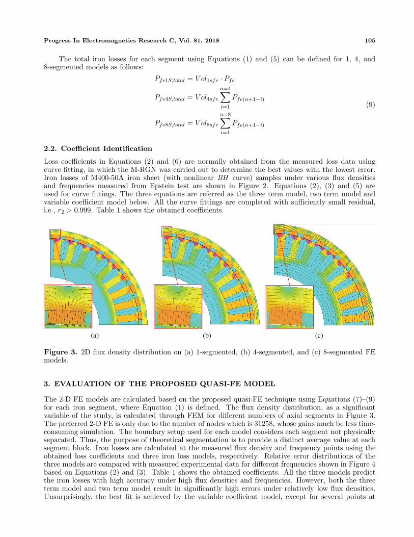
Figure 3. 2D flux density distribution on (a) 1-segmented, (b) 4-segmented, and (c) 8-segmented FEmodels.
3. EVALUATION OF THE PROPOSED QUASI-FE MODEL
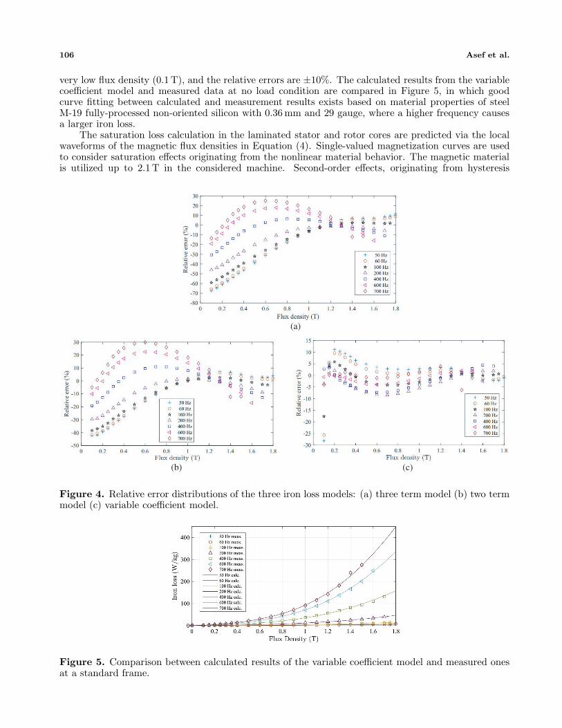
The 2-D FE models are calculated based on the proposed quasi-FE technique using Equations (7)–(9)for each iron segment, where Equation (1) is defined. The flux density distribution, as a significantvariable of the study, is calculated through FEM for different numbers of axial segments in Figure 3.The preferred 2-D FE is only due to the number of nodes which is 31258, whose gains much be less time-consuming simulation. The boundary setup used for each model considers each segment not physicallyseparated. Thus, the purpose of theoretical segmentation is to provide a distinct average value at eachsegment block. Iron losses are calculated at the measured flux density and frequency points using theobtained loss coefficients and three iron loss models, respectively. Relative error distributions of thethree models are compared with measured experimental data for different frequencies shown in Figure 4based on Equations (2) and (3). Table 1 shows the obtained coefficients. All the three models predictthe iron losses with high accuracy under high flux densities and frequencies. However, both the threeterm model and two term model result in significantly high errors under relatively low flux densities.Unsurprisingly, the best fit is achieved by the variable coefficient model, except for several points at
106 Asef et al.
very low flux density (0.1 T), and the relative errors are ±10%. The calculated results from the variablecoefficient model and measured data at no load condition are compared in Figure 5, in which goodcurve fitting between calculated and measurement results exists based on material properties of steelM-19 fully-processed non-oriented silicon with 0.36 mm and 29 gauge, where a higher frequency causesa larger iron loss.
The saturation loss calculation in the laminated stator and rotor cores are predicted via the localwaveforms of the magnetic flux densities in Equation (4). Single-valued magnetization curves are usedto consider saturation effects originating from the nonlinear material behavior. The magnetic materialis utilized up to 2.1 T in the considered machine. Second-order effects, originating from hysteresis
(b)
(a)
(c)
Figure 4. Relative error distributions of the three iron loss models: (a) three term model (b) two termmodel (c) variable coefficient model.
Figure 5. Comparison between calculated results of the variable coefficient model and measured onesat a standard frame.

Progress In Electromagnetics Research C, Vol. 81, 2018 107
Table 1. Loss coefficients obtained from curve fitting.
Coefficient Three term model Two term model Variable coefficient modelh 2.386 2.03 NaNkh 0.02193 0.02193 NaNke 1.845 × 10⁻⁴ 1.845 × 10⁻⁴ NaNka 3.152 × 10⁻⁹ NaN NaNks1 25.7 × 10⁻⁷ 25.12 × 10⁻⁷ 26.2 × 10⁻⁷
ks2 3.6543 3.2313 3.9872h0 NaN NaN 0.2936h1 NaN NaN 0.07778kh0 NaN NaN −0.002409kh1 NaN NaN 4.253 × 10⁻⁶
hh3 NaN NaN 0.02895d NaN NaN 0.01826
ke0 NaN NaN 0.02093ke1 NaN NaN −0.01927ksat 1.043 × 10⁻⁸ 1.001 × 10⁻⁸ 1.361 × 10⁻⁹
(b)(a) (c)
Figure 6. The torque-frequency-saturation loss presentation through the last term of Equation (5) for,(a) the FE one-segmented, (b) FE four-segmented, and (c) eight-segmented techniques.
behavior, are neglected. The saturation term is specifically at the area around the transition point athigh torques and high speeds with a large proportion.
The nonlinear (saturation) loss without segmentation consideration is shown as smaller area ofsignificant loss value of 900 (W) in Figure 6(a). However, through the four-segmented FE model, aslightly larger amount of saturation loss can be reported which is obviously presented via the color barwith a larger critical area by 950 (W) seen in Figure 6(b). The eight-segmented FE model has a largerarea of critical loss which is clearly represented in Figure 6(c). The quasi-FEA technique is limited tothe eight-segmented blocks due to mesh’s size, where a single complete triangle mesh is required at eachblock.
The total iron loss calculation with skin effect consideration for stator and rotor cores is successfullydone through Equation (10) and based on the proposed quasi-FEA technique (in Figure 7), in which alarger amount of iron losses at low and high frequencies can be seen via aid of a color bar at the four-and eight-segmented models that are illustrated in Figures 7(a) and 7(b), respectively. The proposedeight-segmented model using the quasi-FEA technique has estimated a larger significant iron losses, inwhich Figure 7 presents the peak total iron loss for maximum torque of 122 (N.m), at 400 (Hz) by

108 Asef et al.
(b)(a) (c)
Figure 7. Total predicted iron losses using variable coefficient model as function of torque andfrequency, where (a) the typical 2-D FE iron loss modeling, (b) the quasi-2-D-FE technique with four-segmented observation, and (c) the proposed quasi-2-D-FE technique with eight-segmented observation.
2.01, 2.55, and 2.78 (kW) for conventional, four-segmented quasi-FEA, and proposed eight-segmentedquasi-FEA technique, respectively. The proposed eight-segmented quasi-FEA model predicts with alarger area of significant losses than the conventional (Figure 7(a)) and four-segmented techniques dueto a better mesh which is comparable to 3-D FEA.
Accurate calculation of the field harmonics at each single area (more specific by segmentation) ofthe iron parts is the main contribution of the work using a proposed quasi-FE technique. For example,through segmenting one tooth into eight, the tooth-top area is presented with much higher harmonicsand related loss, whereas only considering the absolute value of a full tooth shows lesser filed harmonicsin the critical areas. Additionally, the proposed model (in Figure 7(c)) illustrates a higher amountof iron loss at low frequencies between 0 and 350 (Hz). Moreover, the quality of constancy in torquebetween 0 and 400 (Hz) is a perfect match with the goal of the machine’s operation.
4. 3D FEA AND EXPERIMENTAL VERIFICATIONS
After analyzing the PMSM machine based on the proposed quasi-FEA technique, in which a 2-D FEAis used, the 3-D FEA is investigated along with experimental verification. The Bertotti’s iron lossseparation models are employed to a PMSM with a permanently deliverable torque of 60 (Nm). Thecross section of the laminated stator and rotor core of the twenty pole-pair PMSM under study isshown in Figures 1 and 8. The maximum rotational speed of the machine is 2400 (rpm). A double-layerfractional-slot winding is used to generate the airgap electromagnetic field. The rotor of the investigatedmachine is excited through buried magnets.
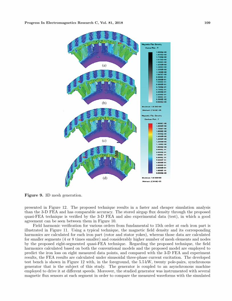
The proposed quasi-FE technique using 2-D FE model is verified with a 3-D FE model, in whichthe mesh is generated with a high quality with 544289 elements, 163013 nodes as shown in Figure 8,and its 3-D FE magnetic flux density distribution (as shown in Figure 9). The experimental setup is
Figure 8. 3D mesh generation.
Progress In Electromagnetics Research C, Vol. 81, 2018 109
(b)
(a)
(c)
(d)
Figure 9. 3D mesh generation.
presented in Figure 12. The proposed technique results in a faster and cheaper simulation analysisthan the 3-D FEA and has comparable accuracy. The stored airgap flux density through the proposedquasi-FEA technique is verified by the 3-D FEA and also experimental data (test), in which a goodagreement can be seen between them in Figure 10.
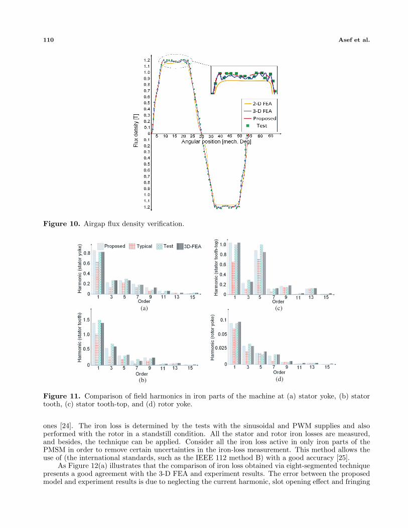
Field harmonic verification for various orders from fundamental to 15th order at each iron part isillustrated in Figure 11. Using a typical technique, the magnetic field density and its correspondingharmonics are calculated for each iron part (rotor and stator yokes), whereas those data are calculatedfor smaller segments (4 or 8 times smaller) and considerably higher number of mesh elements and nodesby the proposed eight-segmented quasi-FEA technique. Regarding the proposed technique, the fieldharmonics calculated based on both the conventional models and the proposed model are employed topredict the iron loss on eight measured data points, and compared with the 3-D FEA and experimentresults, the FEA results are calculated under sinusoidal three-phase current excitation. The developedtest bench is shown in Figure 12 with, in the foreground, the 5.5 kW, twenty pole-pairs, synchronousgenerator that is the subject of this study. The generator is coupled to an asynchronous machineemployed to drive it at different speeds. Moreover, the studied generator was instrumented with severalmagnetic flux sensors at each segment in order to compare the measured waveforms with the simulated
110 Asef et al.
Figure 10. Airgap flux density verification.
(b)
(a) (c)
(d)
Figure 11. Comparison of field harmonics in iron parts of the machine at (a) stator yoke, (b) statortooth, (c) stator tooth-top, and (d) rotor yoke.
ones [24]. The iron loss is determined by the tests with the sinusoidal and PWM supplies and alsoperformed with the rotor in a standstill condition. All the stator and rotor iron losses are measured,and besides, the technique can be applied. Consider all the iron loss active in only iron parts of thePMSM in order to remove certain uncertainties in the iron-loss measurement. This method allows theuse of (the international standards, such as the IEEE 112 method B) with a good accuracy [25].
As Figure 12(a) illustrates that the comparison of iron loss obtained via eight-segmented techniquepresents a good agreement with the 3-D FEA and experiment results. The error between the proposedmodel and experiment results is due to neglecting the current harmonic, slot opening effect and fringing
Progress In Electromagnetics Research C, Vol. 81, 2018 111
(a) (b)
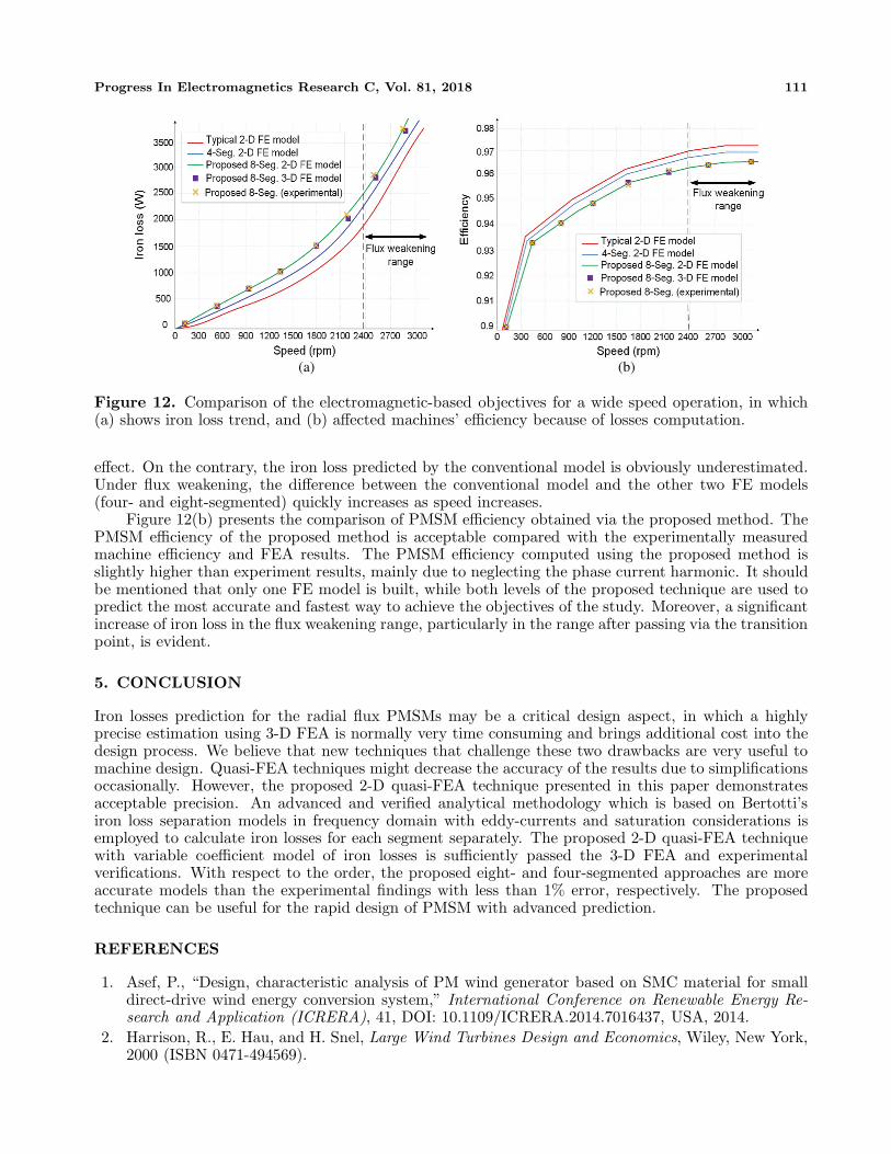
Figure 12. Comparison of the electromagnetic-based objectives for a wide speed operation, in which(a) shows iron loss trend, and (b) affected machines’ efficiency because of losses computation.
effect. On the contrary, the iron loss predicted by the conventional model is obviously underestimated.Under flux weakening, the difference between the conventional model and the other two FE models(four- and eight-segmented) quickly increases as speed increases.
Figure 12(b) presents the comparison of PMSM efficiency obtained via the proposed method. ThePMSM efficiency of the proposed method is acceptable compared with the experimentally measuredmachine efficiency and FEA results. The PMSM efficiency computed using the proposed method isslightly higher than experiment results, mainly due to neglecting the phase current harmonic. It shouldbe mentioned that only one FE model is built, while both levels of the proposed technique are used topredict the most accurate and fastest way to achieve the objectives of the study. Moreover, a significantincrease of iron loss in the flux weakening range, particularly in the range after passing via the transitionpoint, is evident.
5. CONCLUSION
Iron losses prediction for the radial flux PMSMs may be a critical design aspect, in which a highlyprecise estimation using 3-D FEA is normally very time consuming and brings additional cost into thedesign process. We believe that new techniques that challenge these two drawbacks are very useful tomachine design. Quasi-FEA techniques might decrease the accuracy of the results due to simplificationsoccasionally. However, the proposed 2-D quasi-FEA technique presented in this paper demonstratesacceptable precision. An advanced and verified analytical methodology which is based on Bertotti’siron loss separation models in frequency domain with eddy-currents and saturation considerations isemployed to calculate iron losses for each segment separately. The proposed 2-D quasi-FEA techniquewith variable coefficient model of iron losses is sufficiently passed the 3-D FEA and experimentalverifications. With respect to the order, the proposed eight- and four-segmented approaches are moreaccurate models than the experimental findings with less than 1% error, respectively. The proposedtechnique can be useful for the rapid design of PMSM with advanced prediction.
REFERENCES
1. Asef, P., “Design, characteristic analysis of PM wind generator based on SMC material for smalldirect-drive wind energy conversion system,” International Conference on Renewable Energy Re-search and Application (ICRERA), 41, DOI: 10.1109/ICRERA.2014.7016437, USA, 2014.
2. Harrison, R., E. Hau, and H. Snel, Large Wind Turbines Design and Economics, Wiley, New York,2000 (ISBN 0471-494569).
112 Asef et al.
3. Dubois, M. R., “Optimized permanent magnet generator topologies for direct-drive wind tur-bines,”Ph.D. dissertation, Delft Univ. Technol., Delft, The Netherlands, 2004.
4. Grauers, A., “Design of direct-driven permanent-magnet generators for wind turbines,” Ph.D.dissertation, Chalmers Univ. Technol., Goteborg, Sweden, 1996.
5. Poore, R. and T. Lettenmaier, “Alternative design study report: Wind PACT advanced windtur-bine drive train designs study,” NREL, Golden, CO, Rep. NREL/SR-500-33196, Aug. 2003.
6. Cotrell, J. R., “A preliminary evaluation of a multiple-generator drive train configuration for windturbines,” presented at the 2002 ASME Wind Energy Symp., 40th AIAA Aerosp. Sci. MeetingExhibit, Collection Tech. Papers, Reno, NV, Jan. 14–17, 2002.
7. Martin, F., et al., “Improved analytical determination of eddy current losses in surface mountedpermanent magnets of synchronous machine,” IEEE Trans. Magn., Vol. 50, No. 6, 1–8, Jun. 2014.
8. Hemeida, A., et al., “Comparison of methods for permanent magnet eddy-current loss computationswith and without reaction field considerations in axial flux PMSM,” IEEE Trans. Magn., Vol. 51,No. 9, 1–8, Sep. 2015.
9. Kakhki, M. T., et al., “New approach for accurate prediction of eddy current losses in laminatedmaterial in the presence of skin effect with 2-D FEA,” IEEE Trans. Magn., Vol. 52, No. 3, 1–4,Mar. 2016.
10. Huang, W. Y., et al., “Optimization of magnet segmentation for reduction of eddy-current lossesin permanent magnet synchronous machine,” IEEE Trans. Energy Conv., Vol. 25, No. 2, 381–386,2010.
11. Steentjes, S., et al., “Iron-loss model with consideration of minor loops applied to FE-simulationsof electrical machines,” IEEE Trans. Magn., Vol. 49, No. 7, 3945–3948, Jul. 2013.
12. Eggers, D., et al., “Advanced iron-loss estimation for nonlinear material behavior,” IEEE Trans.Magn., Vol. 48, No. 11, 3021–3024, Nov. 2012.
13. Bertotti, G., “General properties of power losses in soft ferromagnetic materials,” IEEE Trans.Magn., Vol. 24, No. 1, Jan., 1988.
14. Bertotti, G. and M. Pasquale “Physical interpretation of induction and frequency dependence ofpower losses in soft magnetic materials,” IEEE Trans. Magn., Vol. 28, No. 5, Sep. 1992.
15. Bertotti, G., et al., “An improved estimation of iron losses in rotating electrical machineS,” IEEETrans. Magn., Vol. 27, No. 6, Nov. 1991.
16. Fratila, M., et al., “Iron loss calculation in a synchronous generator using finite element analysis,”IEEE Tran. Energy Conv., Vol. PP, No. 99, 1–8, doi: 10.1109/TEC.2017.2648512, 2017.
17. Rasilo, P., et al., “Experimental determination and numerical evaluation of core losses in a 150-kVA wound-field synchronous machine,” IET Electric Power App., Vol. 7, No. 2, 97–105, doi:10.1049/iet-epa.2012.02422013.
18. Kowal, D., et al., “Comparison of frequency and time-domain iron and magnet loss modelingincluding PWM harmonics in a PMSG for a wind energy application,” IEEE Trans. EnergyConversion, Vol. 30, No. 2, 476–486, 2015.
19. Pfingsten, G. V., et al., “Operating point resolved loss calculation approach in saturated inductionmachines,” IEEE Trans. Ind. Electr., Vol. 64, No. 3, 2538–2546, 2017.
20. Boglietti, A., A. Cavagnino, M. Lazzari, and M. Pastorelli, “Predicting iron losses in soft mag-neticmaterials with arbitrary voltage supply: An engineering approach,” IEEE Trans. Magn., Vol. 39,No. 2, 981–989, 2003.
21. Krings, A. and J. Soulard, “Overview and comparison of iron loss models for electrical ma-chines,”Journal of Electrical Engineering, Vol. 10, No. 3, 162–169, 2010.
22. Ionel, D. M., M. Popescu, S. J. Dellinger, T. J. E. Miller, R. J. Heideman, and M. I. McGilp, “Onthe variation with flux and frequency of the core loss coefficients in electrical machines,” IEEETrans. Ind. Appl., Vol. 42, No. 3, 658–667, May 2006.
23. Ionel, D. M., M. Popescu, M. I. McGilp, T. J. E. Miller, S. J. Dellinger, and R. J. Heideman,“Computation of core losses in electrical machines using improved models for laminated steel,”IEEE Trans. Ind. Appl., Vol. 43, No. 6, 1554–1564, Nov. 2007.
Progress In Electromagnetics Research C, Vol. 81, 2018 113
24. Huang, Y., J. Dong, J. G. Zhu, and Y. Guo, “Core loss modeling for permanent-magnet motorbased on flux variation locus and finite-element method,” IEEE Trans. Magn., Vol. 48, No. 2,1023–1026, 2012.
25. Gerlando, A. D. and R. Perini, “Evaluation of the effects of the voltage harmonics on the extra ironlosses in the inverter fed electromagnetic devices,” IEEE Trans. on Energy Conv., Vol. 14, No. 1,57–62, Mar. 1999.
26. Lasdon, L. S., et al., “Design and testing of a generalized reduced gradient code for nonlinearoptimization,” Case Western Reserve University, National Technical Information Service U.S. De-partment of Commerce (NTIS), AD-A009-402, 1–45, Mar. 1975.