a critical analysis of the ganter bridge, switzerland...
TRANSCRIPT

A CRITICAL ANALYSIS OF THE GANTER BRIDGE, SWITZERLAND (1980)
Jack Rossiter1
1University of Bath
Abstract: The Ganter Bridge is a cable-stayed structure of total length 678m constructed between 1976 and 1980 in the Valais, Switzerland. Designed by Engineer Christian Menn, on completion it possessed the longest span of any Swiss bridge. It is a good example of the design approach of a master builder, holding aesthetic quality in highest regard but ensuring this never violates technical considerations. This paper considers the design and construction of the bridge, as well as providing analysis of aesthetics and structural strength when subject to relevant primary and secondary loading. A discussion of potential future change and maintenance requirements follows. Throughout, all relevant data has been used, but where unavailable assumptions have been made based on engineering judgement.
Keywords: Cable-stayed, cantilever, prestressed, concrete, Switzerland
1 Background Information
The Ganter Bridge on national highway N9, forms part of the Simplon Pass. Located 10km south of Brig in the Valais, Switzerland, at an altitude of approximately 1450m above mean sea level, its construction over the 'river' Ganter allowed a dangerous 2km stretch of old road to be bypassed.
A tunnel costing 50million Swiss francs had been proposed, but concerned with this high price the canton engineer of Valais consulted the federal highway department in Bern, who recommended Christian Menn. His proposal was so well received that it was commissioned and official competition suspended. This was due in large part to the perception that competition juries can be conservative; without a clear precedent for the design the canton feared it would be rejected.
Menn had explored new forms in the 1960s following the development of prestressed concrete. Steel cables hidden inside a hollow-box girder could replace arches and support the traffic directly allowing bridge structures to be lighter. His previous project had been a cantilever bridge at Felsenau, with relatively long spans of around 150m, specified to avoid piers in the water. He was surprised by the large maximum bending moment on this project and felt that the longer spans over the weak Ganter Valley would produce unacceptable moments and require a fresh approach.
It was necessary to find a design that would satisfy the constraints of an unstable slope on the south side, high wind forces above the valley and the curving roadway between the two sides. The chosen bridge permitted curved plan layout, reduced cantilevers by
providing intermediate supports courtesy of stays and was sensitive to the weak slope conditions. Although largely driven by aesthetics, technical considerations and requirements took precedence. In Menn's words, “the extreme relationship between the extraordinarily powerful pillars and the very narrow bridge girder led to an unusual design for the superstructure."
Figure 1: Ganter Bridge from SW
2 Bridge Aesthetics & Design Considerations
Throughout his career, engineer Fritz Leonhardt was concerned with questions concerning the aesthetic design of building projects. He believes all objects to possess aesthetic qualities and that some buildings reveal certain characteristics of quality, from which we can deduce guidelines for design. His opinions are purely his own, “based largely on observations, years of
1John Rossiter, [email protected]
Proceedings of Bridge Engineering 2 Conference 2008 16/23 April 2008, University of Bath, Bath, UK
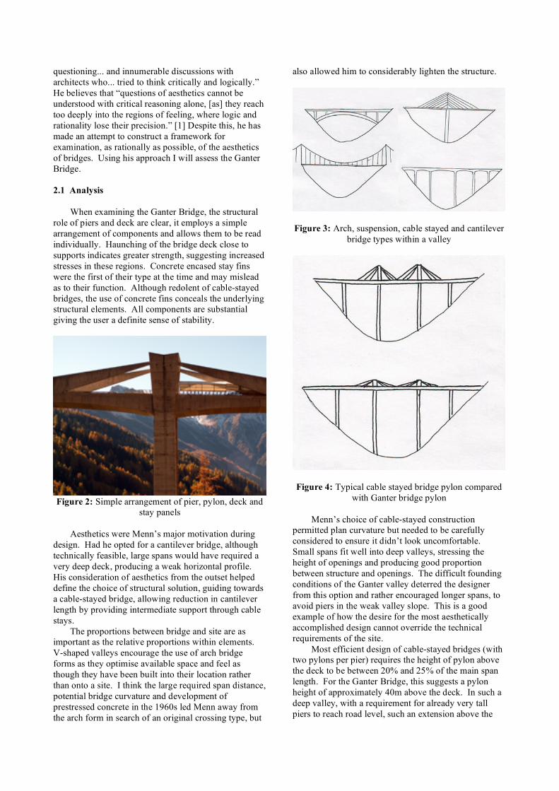
questioning... and innumerable discussions with architects who... tried to think critically and logically.” He believes that “questions of aesthetics cannot be understood with critical reasoning alone, [as] they reach too deeply into the regions of feeling, where logic and rationality lose their precision.” [1] Despite this, he has made an attempt to construct a framework for examination, as rationally as possible, of the aesthetics of bridges. Using his approach I will assess the Ganter Bridge. 2.1 Analysis When examining the Ganter Bridge, the structural role of piers and deck are clear, it employs a simple arrangement of components and allows them to be read individually. Haunching of the bridge deck close to supports indicates greater strength, suggesting increased stresses in these regions. Concrete encased stay fins were the first of their type at the time and may mislead as to their function. Although redolent of cable-stayed bridges, the use of concrete fins conceals the underlying structural elements. All components are substantial giving the user a definite sense of stability.
Figure 2: Simple arrangement of pier, pylon, deck and
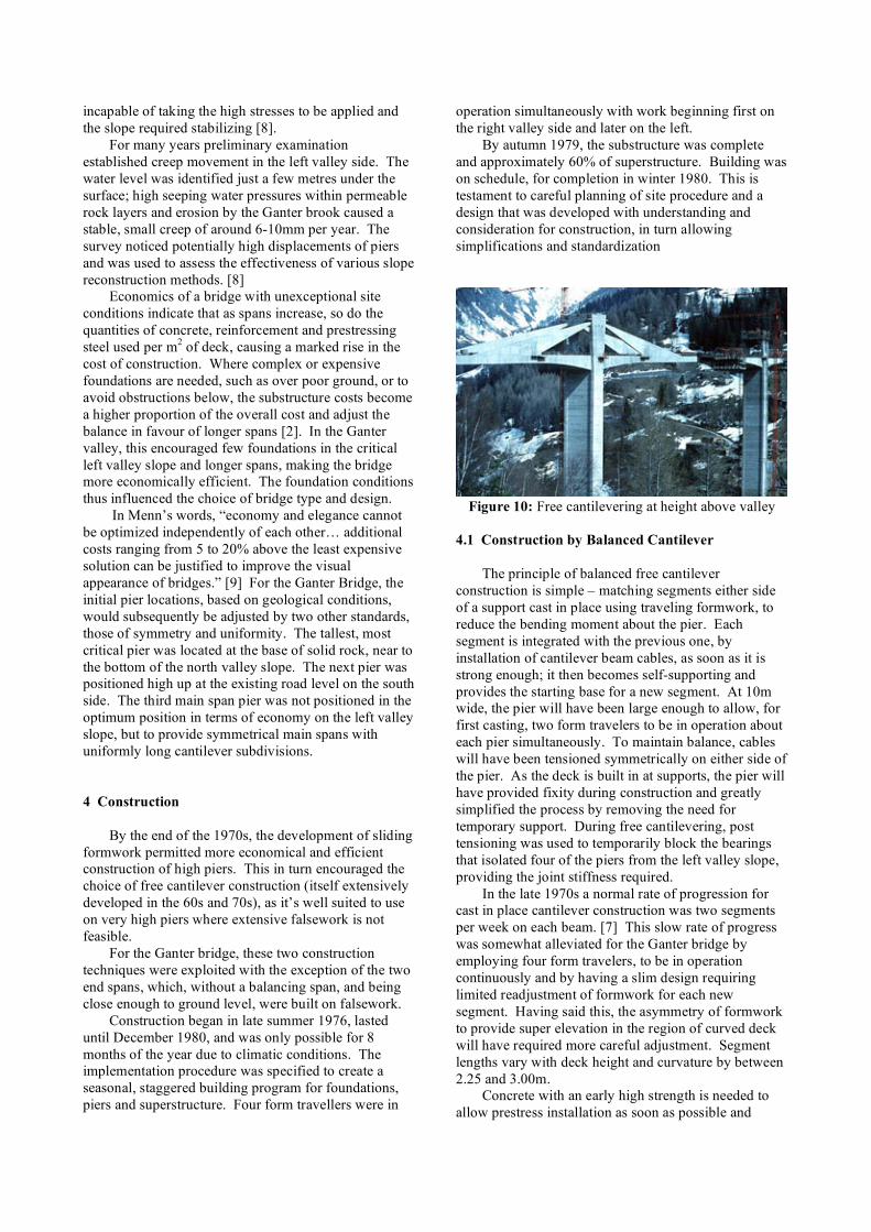
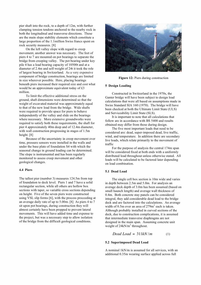
stay panels Aesthetics were Menn’s major motivation during design. Had he opted for a cantilever bridge, although technically feasible, large spans would have required a very deep deck, producing a weak horizontal profile. His consideration of aesthetics from the outset helped define the choice of structural solution, guiding towards a cable-stayed bridge, allowing reduction in cantilever length by providing intermediate support through cable stays. The proportions between bridge and site are as important as the relative proportions within elements. V-shaped valleys encourage the use of arch bridge forms as they optimise available space and feel as though they have been built into their location rather than onto a site. I think the large required span distance, potential bridge curvature and development of prestressed concrete in the 1960s led Menn away from the arch form in search of an original crossing type, but
also allowed him to considerably lighten the structure.
Figure 3: Arch, suspension, cable stayed and cantilever bridge types within a valley
Figure 4: Typical cable stayed bridge pylon compared with Ganter bridge pylon
Menn’s choice of cable-stayed construction
permitted plan curvature but needed to be carefully considered to ensure it didn’t look uncomfortable. Small spans fit well into deep valleys, stressing the height of openings and producing good proportion between structure and openings. The difficult founding conditions of the Ganter valley deterred the designer from this option and rather encouraged longer spans, to avoid piers in the weak valley slope. This is a good example of how the desire for the most aesthetically accomplished design cannot override the technical requirements of the site.
Most efficient design of cable-stayed bridges (with two pylons per pier) requires the height of pylon above the deck to be between 20% and 25% of the main span length. For the Ganter Bridge, this suggests a pylon height of approximately 40m above the deck. In such a deep valley, with a requirement for already very tall piers to reach road level, such an extension above the

deck would make the bridge appear too high for both the total valley width and individual spans, with resulting pylons looking out of proportion and clumsy. By reducing them to approximately 15m, the rise above deck appears minor when compared with pier height, but gives the bridge an elegant flow as the eyes move along the profile, substantially developing its character. Although undisturbed above deck level, such a flow from one valley side to the other would not have been achieved by a simple cantilever bridge.
Spacing piers closer to one another as they rise up the valley sides achieves a balance between height and span. In profile (taking into account the curved side spans) diagonals through the openings maintain the same inclination providing repetition of proportion along the bridge length. Openings provided beneath 'stay panels' work to offset the concealed region around supports providing better balance and emphasising the character of the bridge. Had most efficient pylon height been used, the increased size of stay panel would have produced a much heavier profile near to supports, possibly very hard to moderate with openings, making the bridge look out of proportion.
Figure 5: Stay panel size comparison highlighting difficulties with balance of proportions
The bridge must display a character that is
compatible with its location. The Ganter bridge is strong yet graceful and, while honest in terms of flow of forces, it is deceptive in that, what appears to provide support conceals that which provides it. Here, Menn has created a monolithic structure framed by mountains with sharp and smooth lines in both background and structure. Concrete has connotations of solidity and paired with the robust appearance of the Ganter Bridge is well suited to the mountains, but the structure retains a certain grace that fits very well into the imposing yet calm alpine environment. Proportion is of importance in three-dimensional space and this is where the Ganter Bridge suffers - it exhibits one scale in profile and another in section. The roadway is particularly narrow at 10m wide but when looking along the length, the bridge seems heavy. This appearance is produced by the scale of the high stay walls and deep cross beam joining the two pylons, compared with that of the deck. I wouldn’t say the
bridge is delicate from any angle but although providing the user with a strong sense of stability/solidity, the transverse section is by no means as thought through or refined as the profile.
Figure 6: Drivers’ view of heavy superstructure
The unique (at the time) stay panels give the Ganter bridge a degree of intrigue and surprise. Paired with the plan curvature, as dictated by the site conditions, and varied spacing between piers, the bridge presents variety to the observer. The deck design with a minimal haunch, combined with very simplified pier sections provide sufficient simplicity and order so as not to confuse the image presented. Order is achieved by limiting the direction of lines in a structure to very few. The bridge is formed of three visual components formed of simple lines operating in only three primary directions: piers that rise vertically; deck that follows a horizontal line with slight haunching near to supports repeated throughout; four stay panels symmetrical about pylons, diagonal from tip to deck anchorage. The stays in the main span do not technically require concrete sheathing as they no longer follow plan curvature, but the aesthetic loss by removing the symmetry and order about each pylon necessitates their inclusion. When viewed from an oblique angle (as every driver will experience due to curved road), as cable stays are housed within a concrete sheath, they are not permitted to overlap and interfere with each other. This removes a common problem of order in cable-stayed bridges.
Figure 7: Central span without stay panels

Longitudinally, main piers are 10m wide at the base and taper parabolically to 6.5m width at deck level, while they are straight sided in the transverse plane, giving them a stiff appearance with the top appearing wider than the base from certain angles. The narrow roadway is a single cell box girder with vertical walls and no cantilevers that permits the piers to continue up, around the deck to pylon height, simplifying lines and increasing order in the design. Retaining the superstructure design and connection between pier and deck, there remains only one option to allow piers to look less stiff if a hollow box section is employed. That is to make them wider than 10m at the base which would require more extensive foundations in the weak valley sides, more expensive formwork and more material. Even if this option were chosen, the fact that the pier is full width at deck level will maintain a heavy appearance at connection, so by adding a taper, the extra expense may only go a small way to solving the problem. At the time the construction of high piers was becoming more economical through use of sliding formwork, but the technique was still in its infancy [Mathivat]. If constructed today (assuming no taper applied), the piers may be designed with a non-rectangular section (perhaps octagonal) to influence the way light strikes the pier and affects how large it appears. All services run within the box girder while stay anchorage is hidden so as to create a smooth, undisturbed soffit. A matt finish has been specified for the concrete deck, the texture and colour of which will be uneven from the outset for different castings. Concrete will weather badly, with variations between segments accentuated. The changing colour will fit well with the nearby mountains, themselves subject to weathering, displaying irregularity throughout.
Figure 8: Smooth soffit and variation in concrete colour
When viewed against the light, structure and setting take on a similar colour, particularly at sunrise and sunset, the bridge appearing integral to the valley. Yet, if the sun is incident on the fascia during the day, the bright concrete colour contrasts and conflicts the green of the valley slopes. It has been suggested that
this could be rectified by colouring piers, pylons and stay panels to fit with the surrounds throughout the day, allowing the deck to ‘float’ and the bridge appear less conspicuous at all times. [1] Although this will solve one of the aesthetic issues, it may be a step that results in reduction of bridge character. The use of uniform material, colour and texture throughout, permits clear division of masses and voids in the bridge and valley. Variations in colour or texture may allow gradations between these simple open or closed views and confuse the picture created.
Figure 9: With dark coloured piers and stay panels
Menn states, “Bridges must be compatible with
their environment and visually pleasing as entities unto themselves.” [9] As an engineer he feels that he has a responsibility to design structures that suit their environment rather than shape it. In some situations it is hard to incorporate nature into a bridge design by means of symbolism or addition of organic materials. A design that is compatible with its environment in terms of shape, material, construction procedure and character will have a greatly reduced negative impact on the surrounds. A good design that considers all of the spatial and temporal aspects will incorporate nature by being accepted into the local environment as an important component part. This sympathy in design is exhibited in the Ganter valley.
3 Geological Conditions
The starting point for design of the Ganter Bridge was the support conditions. The right valley side is formed of stratified layers of rock and falls away sharply with an incline of approximately 45° [8]. At this angle, access for construction is limited and there is a chance of any foundation causing rotational or translational slip. The increased risk and associated cost forced Menn to avoid any foundation in the right valley side beneath the existing road. The left valley slope has a significantly lower incline of approximately 25° [8]. Extensive borehole soundings identified layers of blocky rock debris, moraine and schist that was completely weathered and decomposed. After inspection this was considered
incapable of taking the high stresses to be applied and the slope required stabilizing [8]. For many years preliminary examination established creep movement in the left valley side. The water level was identified just a few metres under the surface; high seeping water pressures within permeable rock layers and erosion by the Ganter brook caused a stable, small creep of around 6-10mm per year. The survey noticed potentially high displacements of piers and was used to assess the effectiveness of various slope reconstruction methods. [8] Economics of a bridge with unexceptional site conditions indicate that as spans increase, so do the quantities of concrete, reinforcement and prestressing steel used per m2 of deck, causing a marked rise in the cost of construction. Where complex or expensive foundations are needed, such as over poor ground, or to avoid obstructions below, the substructure costs become a higher proportion of the overall cost and adjust the balance in favour of longer spans [2]. In the Ganter valley, this encouraged few foundations in the critical left valley slope and longer spans, making the bridge more economically efficient. The foundation conditions thus influenced the choice of bridge type and design.
In Menn’s words, “economy and elegance cannot be optimized independently of each other… additional costs ranging from 5 to 20% above the least expensive solution can be justified to improve the visual appearance of bridges.” [9] For the Ganter Bridge, the initial pier locations, based on geological conditions, would subsequently be adjusted by two other standards, those of symmetry and uniformity. The tallest, most critical pier was located at the base of solid rock, near to the bottom of the north valley slope. The next pier was positioned high up at the existing road level on the south side. The third main span pier was not positioned in the optimum position in terms of economy on the left valley slope, but to provide symmetrical main spans with uniformly long cantilever subdivisions. 4 Construction
By the end of the 1970s, the development of sliding formwork permitted more economical and efficient construction of high piers. This in turn encouraged the choice of free cantilever construction (itself extensively developed in the 60s and 70s), as it’s well suited to use on very high piers where extensive falsework is not feasible.
For the Ganter bridge, these two construction techniques were exploited with the exception of the two end spans, which, without a balancing span, and being close enough to ground level, were built on falsework.
Construction began in late summer 1976, lasted until December 1980, and was only possible for 8 months of the year due to climatic conditions. The implementation procedure was specified to create a seasonal, staggered building program for foundations, piers and superstructure. Four form travellers were in
operation simultaneously with work beginning first on the right valley side and later on the left.
By autumn 1979, the substructure was complete and approximately 60% of superstructure. Building was on schedule, for completion in winter 1980. This is testament to careful planning of site procedure and a design that was developed with understanding and consideration for construction, in turn allowing simplifications and standardization
Figure 10: Free cantilevering at height above valley
4.1 Construction by Balanced Cantilever The principle of balanced free cantilever construction is simple – matching segments either side of a support cast in place using traveling formwork, to reduce the bending moment about the pier. Each segment is integrated with the previous one, by installation of cantilever beam cables, as soon as it is strong enough; it then becomes self-supporting and provides the starting base for a new segment. At 10m wide, the pier will have been large enough to allow, for first casting, two form travelers to be in operation about each pier simultaneously. To maintain balance, cables will have been tensioned symmetrically on either side of the pier. As the deck is built in at supports, the pier will have provided fixity during construction and greatly simplified the process by removing the need for temporary support. During free cantilevering, post tensioning was used to temporarily block the bearings that isolated four of the piers from the left valley slope, providing the joint stiffness required. In the late 1970s a normal rate of progression for cast in place cantilever construction was two segments per week on each beam. [7] This slow rate of progress was somewhat alleviated for the Ganter bridge by employing four form travelers, to be in operation continuously and by having a slim design requiring limited readjustment of formwork for each new segment. Having said this, the asymmetry of formwork to provide super elevation in the region of curved deck will have required more careful adjustment. Segment lengths vary with deck height and curvature by between 2.25 and 3.00m. Concrete with an early high strength is needed to allow prestress installation as soon as possible and

achieve a typical cycle time of between 7 or 8 days per segment. Extensive concrete preliminary examinations were carried out before the start of construction to determine the mix that would provide the required concrete properties. In particular, an assessment of strength and reliability of concrete characteristic values when pumped to such altitude. [8]
After extensive adjustment, concrete with 28-day compressive strength of over 40N/mm2 could be provided reliably, but it also needed early strength due to the free cantilever construction process - utilisation of high-class cement (HPC), guaranteed this. [8] The effects of creep in the concrete and relaxation in the steel lead to delicate problems of control of the beams and the continuous redistribution of stresses in the structure. Total creep allowance conforms to Swiss Standard SIA 162 (1970), while allowance for stress induced by shrinkage is well within limits specified by the same code. 4.2 ‘Stay Panels’
Curved plan layout prevented conventional setup of tension support stays. Angular cables were encased within a concrete ‘stay panel’ to accommodate the curvature. Following completion of the free cantilever, cable strength was achieved by heavy post-tensioning to a level so that under live load tensile stress in the sheaths does not occur.
The manufacture of ‘stay panels’ was very expensive but offers advantages when compared with normal stays:
Damage to the few stays that have had to be replaced or repaired in the past has been, in general, caused by corrosion. [2] Here, the concrete ‘stay panel’ provides full sheathing of all cables and associated corrosion resistance. It should be noted however that these cables in their grouted state cannot be removed individually. They are harder to monitor than standard cables and although the risk of corrosion is lower, the impact would be larger, particularly because water that has entered the sheath can almost certainly not drain out easily, providing long term conditions for corrosion.
As cables are bonded to the concrete, there is a much smaller tension fluctuation, only 1/5th the range of stress change of cables in a normal stayed bridge. This greatly reduces the danger of fatigue and allows fuller utilisation of the tension steel.
A greatly enlarged effective cable cross-section results in substantially higher system stiffness, particularly close to supports. Torsional rigidity is provided to the deck and bonded cables cannot become slack. A fan arrangement is the most efficient in terms of generating the support for the deck, requiring least weight of stay material. The ‘stay-panels’ used here permit use of a fan arrangement, as access need not be provided to stay anchorage. Suggested spacing of stay anchorage to the deck is between 6 and 12m depending on segment size. [2] This is for both aesthetic reasons
and to provide sufficient wind permeability through the fan. The ‘stay panel’ removes the aesthetic difficulty and impermeability will have been factored into design wind loading. I assume a stay from either side of the bridge to support a single segment, that is, an efficient stay spacing of approximately 3m, with associated reduced bending moments between supports when compared with standard construction.
Figure 11: Presumed cable stay arrangement within sheathing
Other minor advantages arise; for example, the
sheathing meets the requirement that normal stay cables be protected to a height of approximately 2m against various risks of accident, such as vehicle impact. The manufacture of ‘stay panels’ would not have bean possible if it had not allowed great savings in construction. Stays that provide intermediate support reduce the cantilever and allow reduction of haunching close to piers. With deck depth only varying between 2.5m and 5.0m, greater standardization of formwork was permitted, providing both a constructional advantage in terms of time and an economical advantage from reduced formwork expense. 4.3 Foundations
Complex, demanding and variable geological conditions throughout the valley required different solutions for pier foundations. Extensive security provisions were required for the rock lying foundations on the right valley slope, especially during construction of shaft foundations for piers 2 and 3.
The foundation of the tallest pier (3) consists of two rectangular shafts, filled entirely with reinforced concrete to a depth of approximately 25m. Two shafts were specified in order to avoid a broad cut in the heavily fissured rock. Its proximity to the brook required careful consideration in light of potential erosion and seeping water running near to the surface, throughout the valley. It was decided that at a cost of 300,000 Swiss Francs, the brook be redirected, allowing the foundation to be properly embedded in rock and reducing conflict between rushing water and construction spoil [8]. The pier foot is additionally anchored by tendons in many places in the rock. This anchorage is, above all, a measure to stabilise the foot of the slope but also provides stability for pier foundations.
The foundation of pier S2 is an extension of the
pier shaft into the rock, to a depth of 12m, with further clamping tension tendons anchored to the nearby rock in both the longitudinal and transverse directions. These are the main slope stability elements which constitute a large proportion of the 1.1million Swiss francs spent on rock security measures. [8]
On the left valley slope with regard to creep movement, another answer was necessary. The feet of piers 4 to 7 are mounted on pot bearings to separate the bridge from creeping valley. The pot bearing under key pile 4 has a load bearing capacity of 10500t and at a diameter of 2.4m and self-weight of 24t it took the role of largest bearing in Switzerland. As a very expensive component of bridge construction, bearings are limited in size wherever possible. Here, placing bearings beneath piers increased their required size and cost what would be an approximate equivalent today of £3 million.
To limit the effective additional stress on the ground, shaft dimensions were determined so that the weight of excavated material was approximately equal to that of the new load from the bridge. Wide shafts were required to provide space for piers to behave independently of the valley and slide on the bearings where necessary. More extensive groundworks were required to satisfy both these requirements, the shaft for pier 4 approximately 40m deep and of 12.4m diameter, with wall construction progressing in stages of 1.5m height. [8]
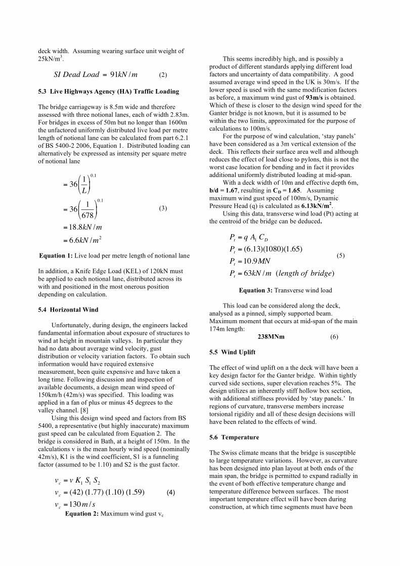
Because of the uncertainty in creep movement over time, pressure sensors were installed in the walls and under the base plate of foundation S4 with which the seasonal change in ground loading can be determined. The slope is instrumented and has been regularly monitored to assess creep movement and other geological changes. 4.4 Piers The tallest pier (number 3) measures 124.5m from top of foundation to deck level. Piers 1 and 7 have a solid rectangular section, while all others are hollow box sections with taper, so variable cross sections depending on height. Five of the seven piers were constructed using VSL slip forms [6], with the process proceeding at an average daily rate of up to 5.00m. [8] As piers 4 to 7 sit upon pot bearings, during construction they will almost certainly have been propped to prevent lateral movements. This will have added time and expense to the project, but was a necessary step to allow isolation of the bridge from the difficult geological conditions.
Figure 12: Piers during construction 5 Design Loading
Constructed in Switzerland in the 1970s, the Ganter bridge will have been subject to design load calculations that were all based on assumptions made in Swiss Standard SIA 160 (1970). The bridge will have been checked at both the Ultimate Limit State (ULS) and Serviceability Limit State (SLS).
It is important to note that all calculations that follow are in accordance with BS 5400 and results obtained may differ from those during design.
The five most important loads that need to be considered are: dead, super-imposed dead, live traffic, wind, and temperature. In addition there are secondary live loads, which relate primarily to the movement of traffic
For the purpose of analysis the central 174m span will be considered fixed at both ends with a uniformly distributed load throughout unless otherwise stated. All loads will be calculated to be factored later depending on load combination. 5.1 Dead Load
The single cell box section is 10m wide and varies in depth between 2.5m and 5.0m. For analysis an average deck depth of 3.0m has been assumed (based on small haunch length) and average wall thickness of 0.4m. Both concrete stay panels can be considered integral, they add considerable dead load to the bridge deck and are factored into the calculations. An average width of 0.5m over an area of 279m2 each is taken. Although probably installed in curved sections of the deck, due to construction complications, it is assumed that intermediate transverse diaphragms are not designed in the main span. Assuming concrete unit weight of 24kN/m3 throughout.
!
Dead Load = 311kN /m (1) 5.2 Superimposed Dead Load A nominal 1kN/m is assumed for all services, with an additional 0.35m wearing surface applied across full
deck width. Assuming wearing surface unit weight of 25kN/m3.
!
SI Dead Load = 91kN /m (2) 5.3 Live Highways Agency (HA) Traffic Loading The bridge carriageway is 8.5m wide and therefore assessed with three notional lanes, each of width 2.83m. For bridges in excess of 50m but no longer than 1600m the unfactored uniformly distributed live load per metre length of notional lane can be calculated from part 6.2.1 of BS 5400-2 2006, Equation 1. Distributed loading can alternatively be expressed as intensity per square metre of notional lane
!
= 361
L
"
# $ %
& '
0.1
= 361
678
"
# $
%
& '
0.1
=18.8kN /m
= 6.6kN /m2
(3)
Equation 1: Live load per metre length of notional lane In addition, a Knife Edge Load (KEL) of 120kN must be applied to each notional lane, distributed across its with and positioned in the most onerous position depending on calculation. 5.4 Horizontal Wind
Unfortunately, during design, the engineers lacked fundamental information about exposure of structures to wind at height in mountain valleys. In particular they had no data about average wind velocity, gust distribution or velocity variation factors. To obtain such information would have required extensive measurement, been quite expensive and have taken a long time. Following discussion and inspection of available documents, a design mean wind speed of 150km/h (42m/s) was specified. This loading was applied in a fan of plus or minus 45 degrees to the valley channel. [8]
Using this design wind speed and factors from BS 5400, a representative (but highly inaccurate) maximum gust speed can be calculated from Equation 2. The bridge is considered in Bath, at a height of 150m. In the calculations v is the mean hourly wind speed (nominally 42m/s), K1 is the wind coefficient, S1 is a funneling factor (assumed to be 1.10) and S2 is the gust factor.
!
vc
= v K1 S1 S2
vc
= (42) (1.77) (1.10) (1.59)
vc
=130m /s
(4)
Equation 2: Maximum wind gust vc
This seems incredibly high, and is possibly a
product of different standards applying different load factors and uncertainty of data compatibility. A good assumed average wind speed in the UK is 30m/s. If the lower speed is used with the same modification factors as before, a maximum wind gust of 93m/s is obtained. Which of these is closer to the design wind speed for the Ganter bridge is not known, but it is assumed to be within the two limits, approximated for the purpose of calculations to 100m/s.
For the purpose of wind calculation, ‘stay panels’ have been considered as a 3m vertical extension of the deck. This reflects their surface area well and although reduces the effect of load close to pylons, this is not the worst case location for bending and in fact it provides additional uniformly distributed loading at mid-span.
With a deck width of 10m and effective depth 6m, b/d = 1.67, resulting in CD = 1.65. Assuming maximum wind gust speed of 100m/s, Dynamic Pressure Head (q) is calculated as 6.13kN/m2.
Using this data, transverse wind load (Pt) acting at the centroid of the bridge can be deduced.
!
Pt = q A1 CD
Pt = (6.13)(1080)(1.65)
Pt =10.9MN
Pt = 63kN /m (length of bridge)
(5)
Equation 3: Transverse wind load
This load can be considered along the deck,
analysed as a pinned, simply supported beam. Maximum moment that occurs at mid-span of the main 174m length:
238MNm (6) 5.5 Wind Uplift The effect of wind uplift on a the deck will have been a key design factor for the Ganter bridge. Within tightly curved side sections, super elevation reaches 5%. The design utilizes an inherently stiff hollow box section, with additional stiffness provided by ‘stay panels.’ In regions of curvature, transverse members increase torsional rigidity and all of these design decisions will have been related to the effects of wind. 5.6 Temperature The Swiss climate means that the bridge is susceptible to large temperature variations. However, as curvature has been designed into plan layout at both ends of the main span, the bridge is permitted to expand radially in the event of both effective temperature change and temperature difference between surfaces. The most important temperature effect will have been during construction, at which time segments must have been

cast at similar temperatures to prevent differentiation between pieces. Construction was only permitted for 8 months of the year to allow this. 5.7 Horizontal Centrifugal Loading Tight plan curvature of the bridge results in moderate loading perpendicular to the direction of travel. Centrifugal loads are to be applied in two notional lanes at 50m centres, in unison with a 400kN vertical live load in each notional lane, distributed over a distance of 6m.
!
Fc
=40000
r +150=40000
350=114kN (7)
Equation 4: Nominal centrifugal load 6 Strength Assessment 6.1 Compressive force in deck under all permanent loads plus primary live loads Under load case 1, load factors are:
!
Dead : " f 3 =1.15 " fl =1.15
DeadSI " f 3 =1.15 " fl =1.75
HA " f 3 =1.15 " fl =1.50
From section 6, (1), (2) and (3) and with these load factors, the uniformly distributed load per m length of bridge.
!
Dead = (1.15)(1.15)(311) = 411kN /m
DeadSI
= (1.15)(1.75)(91) =183kN /m
HA = (1.15)(1.50)(3)(18.8) = 97kN /m
Total = 691kN /m
(8)
Figure 14: Assumed stay panel dimensions Assuming stays are spaced at 3m intervals along
the bridge deck throughout panels, each stay (considering one on either side) will support 1037kN vertical load.
Assuming true fan arrangement and the dimensions as shown in Figure 14, average cable inclination throughout panel is 13.8° .
!
T =1037
Sin(13.8)= 4.35MN
C = (4.35)(Cos(13.8)) = 4.22MN
(9)
Compression (C) in the deck is greatest next to the
pylon courtesy of cumulative effect of cable compression. This is equal to the compressive force provided by all of 17 average cables (length of stay panel interactive with deck divided by 3m per panel) plus that force imparted by cable that is closest to deck.
For the purpose of analysis, a conservative assumption is assumed; the stay cable closest to deck is considered responsible for all deck vertical load between pylon and beginning of panel. In reality, the portion of deck closest to pylon will behave more as a cantilever and will carry load in bending. Using a similar dimensional analysis to resolve forces this cable provides a compressive force of 36MN.
The combined resultant compressive force in deck close to pylon is as shown in Equation 5, it is possible to represent this as a stress to ensure it is within compressive limits of 40N/mm2 as specified during construction. [8]
!
"C = (17)(4.22) + (36)
"C =108MN
# =("C).2
A
# =216MN
11.36x106
=19N /mm2
(10)
Equation 5: Cable induced compressive section stress
6.2 Horizontal Wind Resistance At mid-span the maximum moment calculated due to transverse wind load is 238MN (6). Stresses in the extreme fibres shall be calculated to ensure they are within material capacity. Assuming a mid-span section depth of 2.5m and average wall thickness of 0.4m as before.
!
" =My
I
" =(238x10
9)(1250)
9.25x10¹²
" = 32N /mm2
(11)
Equation 6: Stress in extreme fibres
This stress acts in both compression and tension.
Steel tendons will take tension, while the compression must be resisted by the 40N/mm2 capacity of concrete. This is quite close to the theoretical concrete capacity. At mid-span external stays provide no compression to

the deck, however, there will be prestress within the box, which is likely to be greater than that required to exceed nominal capacity.
Conservative analysis is most likely to have caused this, considering the main span to be simply supported at piers when in reality the degree of fixity reduces moment at mid span. As one moves towards piers, compression in the deck due to cable-stays will increase, while compression as a result of wind will decrease. These two will have been carefully balanced to provide a deck that is working as close to its capacity as possible throughout. 7 Other Factors 7.1 Creep
The redistribution of bending stresses caused by long-term deformations due to creep of concrete is a well known action. It will have been monitored throughout construction and alleviated by adjustment of cable tensions. It is possible to reduce the impact creep can have on a bridge by rigidly connecting the ends of opposing cantilevers, limiting the effect of creep under self-weight, as employed in the construction of the Ganter Bridge.
Following cantilever construction, the point of connection at midspan will not have been designed as a hinge. By creating a continuous deck, the deformations associated with creep are reduced.
To further reduce creep effects, precast segments may be used, which have aged and undergone a large proportion of stress redistribution. This was not an option in the Ganter Valley as it would not have been feasible to hoist sections to deck height. 7.2 Future Changes
Being part of a well-established, tricky mountain pass, there is little evidence to suggest this bridge will require expansion. The two-lane roads that join at both ends are highly unlikely to be changed, so the bridge will almost certainly remain in its current state for years to come. 7.3 Maintenance
It is important to note that although the number of lanes is very unlikely to increase, with vehicle sizes growing, the live load capacity may rise - although trucks do not typically traverse this mountain route.
The bridge has been subject to extensive rehabilitation since construction, a feat that is made particularly complicated by encased cable-stays. The extra expense of maintenance may have been factored into design, although it is more likely not to have been a decisive factor.
Figure 13: Example scaffolding required for
maintenance 8 Acknowledgements
Most of all I would like to thank The University of Oxford for extending their library services to students across England – this resource is invaluable. 10 References [1] Leonhardt, F., 1984. Bridges, Aesthetics and
Design. The MIT Press.
[2] Hewson, N., 2003, Prestressed Concrete Bridges: Design and Construction. Thomas Telford Publishing
[3] Billington, D., 1990, Robert Maillart and the Art of Reinforced Concrete. The MIT Press.
[4] Billington., D, 2003, The Art of Structural Design, A Swiss Legacy, Princeton University Art Museum
[5] Benaim, R., 2008, The Design of Prestressed Concrete Bridges. Taylor and Francis.
[6] Billington, D., 1983, The Tower and the Bridge, Basic Books Inc.
[7] Mathivat, J., 1983, The Cantilever Construction or Prestressed Concrete Bridges, John Wiley & Sons.
[8] Menn, C., Rigendinger, H., 1979. Ganterbrucke, Schweizer Ingenieur und Architekt, Vol. 97, No. 3, pp. 733-739
[9] Menn, C., 1996. The Place of Aesthetics in Bridge Design, Structural Engineering International, Vol. 6, No. 2, pp. 93-95
[10] http://www.vsl.com/index.php?option=com_content&task=view&id=82&Itemid=188 [Accessed 13/03/2008]
[11] http://en.structurae.de/structures/data/index.cfm?id=s0000026 [Accessed 10/03/2008]