a fast mechanical switch for medium voltage hybrid dc and
TRANSCRIPT

A Fast Mechanical Switch for Medium VoltageHybrid DC and AC Circuit Breakers
Chang Peng,Iqbal Husain and Alex HuangFREEDM Systems Center
North Carolina State University
Raleigh, NC 27606, USA
Email: [email protected]
Bruno LequesneE-Motors Consulting, LLC
Menomonee Falls, WI 53051, USA
Email: [email protected]
Roger BriggsEnergy Efficiency Research, LLC
Colgate, WI 53017, USA
Email: [email protected]
Abstract—The paper presents the design and experimentalresults of a Thomson coil based fast mechanical switch for hybridAC and DC circuit breakers rated at 30 kV voltage and 630 Acurrent. The compact design with optimized circuit parametersand geometric dimensions of components targets 2 mm travelwithin 1 ms when driven by a 2 mF capacitor bank pre-chargedto 500 V. The use and design of a disc spring as the dampingand holding mechanism is presented. Structural design of acomplete switch assembly rather than just the actuator is given.Experimental results show that the switch can travel 1.3 mm inthe first 1 ms, and 3.1 mm in the first 2 ms when driven by a 360V 2 mF capacitor bank. Such fast mechanical switches facilitatehybrid circuit breaker interruptions within 2 or 3 millisecondsfor ultra fast and highly efficient protections in 5 - 35 kV mediumvoltage DC as well as AC systems.Index Terms—Finite element method, fast mechanical switch,
actuator, Thomson coil, repulsion coil, operating mechanism,hybrid circuit breaker, DC circuit breaker.
I. INTRODUCTION
The resurgence of interest in DC power for various appli-
cations presents an opportunity as well as a challenge for DC
circuit breaker design. At power transmission and distribution
level, the lack of fast and powerful high voltage DC circuit
breakers impede the extension of modern DC grids [1, 2]. The
conventional mechanical HVDC circuit breakers are too slow
to provide fault interruption in a meshed DC system [3, 4].
While solid state devices can be more than fast enough to
switch off current without arcing, their conduction losses are
prohibitively high [5]. A promising approach is a hybrid con-
figuration, which combines mechanical and electronic switches
[6–9]. The mechanical branch conducts the current during
normal operation and hence loss is minimized. During faults,
the current is commutated to the electronic switch path for
interruption such that the interrupter opens the contactor with
zero current. While being developed for DC, this concept is
likely to be of advantage for AC circuits as well. For best
electrical protection, very fast contact opening is desirable
since this mechanical opening dominates the total interruption
time of the circuit breaker. For medium voltage circuit break-
ers, the currently used solenoid actuators usually take tens
of milliseconds up to more than one hundred milliseconds.
The desirable features of such mechanical switches for hybrid
circuit breakers are:
1) Low conduction loss when carrying current;
2) Very fast opening operation;
3) High arc voltage and durability (optional, depending on
the specific hybrid scheme used).
Fast mechanical switches suitable for this application are
far from being readily available and are only discussed in a
limited number of publications. According to some researchers
[10], the mechanism based on repulsion coil, which is also
called Thomson coil, can achieve much faster mechanical
operation compared to the magnetic mechanism. With regards
to Thomson coils, prior studies reported analytic calcula-
tion methods for repulsive force and movement estimation,
and also presented limited experimental evaluations [11–13].
Testing of a few prototypes was presented in the litera-
ture in the late 1990’s and 2000’s, but these were without
any design guidelines [14–16]. Recent studies report finite-
element-analysis (FEA) based modeling and testing results,
and also alternative operating concepts, but none of these
have implemented switch prototypes with current ratings for
targeted applications [17, 18]. This paper complements an
earlier publication [19] and presents the design and exper-
imental results for a Thomson coil based fast mechanical
switch for 30 kV voltage level and 630 A current level. The
electromagnetic, structural and thermal responses of the switch
have been analyzed through simulation using a multi-physics
finite element software COMSOL. The design guidelines are
derived in terms of circuit and geometric parameters based on
finite element simulations. The prototype has been designed to
achieve a minimum of 2 mm open distance (equivalent to 30
kV dielectric strength in vacuum) within 1 ms. Both electric
and mechanical considerations aspects are discussed in order
to obtain an efficient, compact and robust design. The four
main parts (namely the vacuum interrupter (VI), the operating
mechanism, the holding and damping system, and the energy
storage and control unit) were tested, and the results are
included in this paper. Experimental results of the integrated
prototype on the switching and conducting operations are also
978-1-4673-7151-3/15/$31.00 ©2015 IEEE 5211

Vacuum interrupter:Contacts;Vacuum chamber;Terminals.
Operating mechanism:Copper disk;Opening and closing coils;Insulating layers;Connecting rod.
Damping and holding mechanism:Disc spring;Connecting rod.
Energy storage and control:Capacitor;Semiconductors.
Fig. 1: Structure of the fast switch.
presented.
The operation principles and the modeling are presented in
Section II and Section III respectively; parameters and key
simulation results are explained for a baseline case in this
section. Section IV gives a design description of the switch
with the target ratings. Section V reports the structural design
and includes some mechanical operations. Section VI shows
some experimental results while Section VII concludes the
paper.
II. OPERATION PRINCIPLE
The principles of the fast opening and closing operations of
the Thomson coil based switch are explained, and the main
components are discussed in this section.
A. Opening and closing operations
Referring to Fig. 1, the four main parts of the fast me-
chanical switch are: interrupter, operating mechanism, energy
storage and control, and damping and holding mechanism.
When the switch is must open, the trip signal is sent to the
control switch for the opening coil, this switch turns on, and
allows the pre-charged capacitor bank to discharge through
the opening coil. In Fig. 1, the upper coil is for the opening
and the lower one is for the closing operation. The fast rising
discharge current in the coil induces current in the copper disk,
located between the opening and closing coils, which results in
a strong repulsive force between the coil and copper disk. As
the coil is held firmly by its container on a stationary frame,
the copper disk will be repulsed to move downward and open
the switch. This movement is stopped by a disc spring with
the hold and latch mechanism. This spring absorbs some of
the mechanism kinetic energy, thus damping the movement
before the stop is reached.
The closing operation is accomplished in a similar way by
turning on a second switch that controls the discharge through
the closing coil. Then the copper disk moves upward to close
the contacts. It should be noted that, in the hybrid circuit
breakers that consist of semiconductor switches as a parallel
branch, the requirements for the closing operation, in terms of
fast actuation, are much less stringent than for opening.
B. Main parts
1) Interrupter: The interrupter has to conduct current withvery low losses and disconnect the circuit quickly by providing
a galvanic isolation distance between contacts. the interrupter
is used as a disconnector or as a set of contacts and does not
have to extinguish a burning arc if the current is commutated
to a bypass conducting path before it opens. The implemented
prototype uses a vacuum interrupter for the purpose of with-
standing the medium voltage with a small gap and minimizing
the overall size of the unit. In this experimental set-up, a
vacuum interrupter is used.
2) Operating mechanism: Four types of operating mech-anisms are commonly used in commercial products: spring,
pneumatic, hydraulic and magnetic mechanisms. In vacuum
circuit breakers, the spring and magnetic mechanisms are most
common.
Spring operated mechanisms have been widely used for
vacuum as well as SF6 circuit breakers but they exhibit
mechanical delays because of too many moving parts and
large moving masses. Magnetic mechanisms often come with
vacuum interrupters because they are suitable for short stroke
movement with fewer moving parts [20]. Examples are com-
mercial products such as ABB AMAVC series medium voltage
circuit breakers.
Compared to magnetic mechanisms which consist of coils of
many turns, Thomson coil mechanisms have a limited number
of turns for the coil but significantly higher current. Because
of the small number of turns, the inductance is small and
the energization is quick which is preferred for very fast
operation. Considering the challenges with the pneumatic and
hydraulic actuators, and the faster actuation characteristics of
electromagnetic actuation, the Thomson coil based operating
mechanism has been chosen for this research.
3) Energy storage and control: As high current magnitudeand high di/dt are both required, capacitor banks are used to
store electric energy beforehand such that the energy can be
delivered quickly into the coil when actuation is desired. The
voltage ratings of capacitors range from several hundreds to
thousands of Volts and the discharge current could reach to
more than ten kAs; a dedicated charging circuit is used for
the energy storage. Power semiconductor switches are used to
control the discharge of the capacitors. Thyristors and IGCTs
are often used because of their high surge current capability.
4) Damping and holding mechanism: A holding mecha-
nism or a latch for the closed position provides a holding
force that helps achieve low contact resistance and keeps
the contacts reliably closed even during short circuit current.
When opened, it holds the contacts in open position as required
to avoid undesirable re-closing. A customized disc spring (also
called Belleville spring) was designed and manufactured for
this purpose because of the simple and compact structure of
such springs, and the mechanism characteristics are explained
in Section IV.
5212
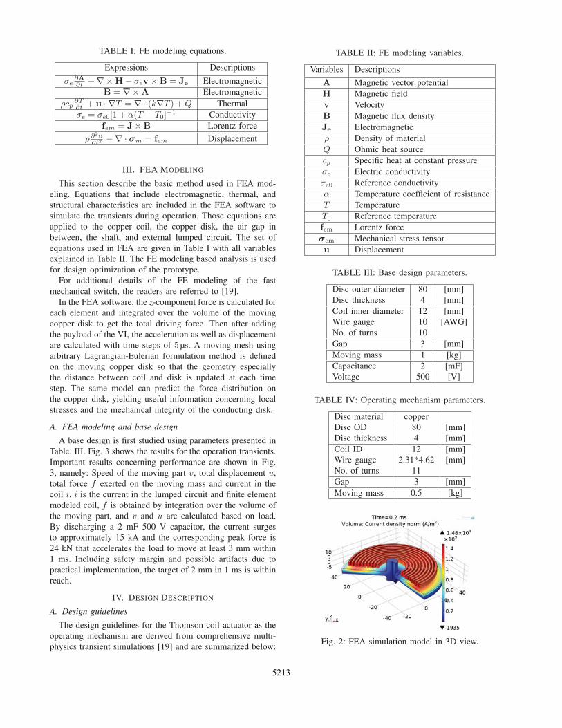
TABLE I: FE modeling equations.
Expressions Descriptions
σe∂A∂t +∇×H− σev ×B = Je Electromagnetic
B = ∇×A Electromagnetic
ρcp∂T∂t + u · ∇T = ∇ · (k∇T ) +Q Thermal
σe = σe0[1 + α(T − T0]−1 Conductivity
fem = J×B Lorentz force
ρ∂2u∂t2 −∇ · σm = fem Displacement
III. FEA MODELING
This section describe the basic method used in FEA mod-
eling. Equations that include electromagnetic, thermal, and
structural characteristics are included in the FEA software to
simulate the transients during operation. Those equations are
applied to the copper coil, the copper disk, the air gap in
between, the shaft, and external lumped circuit. The set of
equations used in FEA are given in Table I with all variables
explained in Table II. The FE modeling based analysis is used
for design optimization of the prototype.
For additional details of the FE modeling of the fast
mechanical switch, the readers are referred to [19].
In the FEA software, the z-component force is calculated foreach element and integrated over the volume of the moving
copper disk to get the total driving force. Then after adding
the payload of the VI, the acceleration as well as displacement
are calculated with time steps of 5 μs. A moving mesh using
arbitrary Lagrangian-Eulerian formulation method is defined
on the moving copper disk so that the geometry especially
the distance between coil and disk is updated at each time
step. The same model can predict the force distribution on
the copper disk, yielding useful information concerning local
stresses and the mechanical integrity of the conducting disk.
A. FEA modeling and base design
A base design is first studied using parameters presented in
Table. III. Fig. 3 shows the results for the operation transients.
Important results concerning performance are shown in Fig.
3, namely: Speed of the moving part v, total displacement u,total force f exerted on the moving mass and current in thecoil i. i is the current in the lumped circuit and finite elementmodeled coil, f is obtained by integration over the volume ofthe moving part, and v and u are calculated based on load.By discharging a 2 mF 500 V capacitor, the current surges
to approximately 15 kA and the corresponding peak force is
24 kN that accelerates the load to move at least 3 mm within
1 ms. Including safety margin and possible artifacts due to
practical implementation, the target of 2 mm in 1 ms is within
reach.
IV. DESIGN DESCRIPTION
A. Design guidelines
The design guidelines for the Thomson coil actuator as the
operating mechanism are derived from comprehensive multi-
physics transient simulations [19] and are summarized below:
TABLE II: FE modeling variables.
Variables Descriptions
A Magnetic vector potential
H Magnetic field
v Velocity
B Magnetic flux density
Je Electromagnetic
ρ Density of material
Q Ohmic heat source
cp Specific heat at constant pressure
σe Electric conductivity
σe0 Reference conductivity
α Temperature coefficient of resistance
T Temperature
T0 Reference temperature
fem Lorentz force
σem Mechanical stress tensor
u Displacement
TABLE III: Base design parameters.
Disc outer diameter 80 [mm]
Disc thickness 4 [mm]
Coil inner diameter 12 [mm]
Wire gauge 10 [AWG]
No. of turns 10
Gap 3 [mm]
Moving mass 1 [kg]
Capacitance 2 [mF]
Voltage 500 [V]
TABLE IV: Operating mechanism parameters.
Disc material copper
Disc OD 80 [mm]
Disc thickness 4 [mm]
Coil ID 12 [mm]
Wire gauge 2.31*4.62 [mm]
No. of turns 11
Gap 3 [mm]
Moving mass 0.5 [kg]
Fig. 2: FEA simulation model in 3D view.
5213

Fig. 3: Opening operation curves.
1) The unidirectional circuit shown in Fig. 1 is better than
a bidirectional circuit in terms of the operating speed of
the mechanism. The components in both circuits used for
evaluation have the same current and voltage ratings.
2) A device with higher voltage, and lower capacitance
but with the same stored energy generates higher and earlier
peak current and peak force. This is preferred for high speed
operation; but this also requires higher semiconductor device
ratings.
3) To design a switch that is required to open within
1 ms, it is useful to design a Thomson coil and capacitor
with a resonant frequency somewhat above 1 kHz (resonant
frequency as defined by the capacitor bank and the coil
inductance), such that the force peaks in the first quarter cycle,
and then optimize the geometry accordingly.
4) Higher voltage or larger capacitance will drive the
mechanism to a faster speed, but will add both mechanical
and electrical stresses on the components.
5) Copper disks with thickness in the range of 2-5 mm
result in almost the same operation speed (see [19], these
thicknesses are somewhat larger than the skin depth at the
design frequency); coils made with AWG 8-12 wires give al-
most the same operation speed. Therefore they are considered
not sensitive in these ranges.
6) To achieve fast opening, the gap between disk and coil
should be kept to a minimum. The disk and the coil outer
diameters should be kept the same, which will give better
coupling between disk and coil.
B. Vacuum interrupter
The vacuum interrupter selected is originally designed for
12 kV AC contactors rated at 630 A with a maximum
allowable stroke of 6 mm. 1 mm in vacuum is equivalent to
15 - 20 kV voltage withstand capability. The most important
VI parameters are given in Table. V.
C. Operating mechanism
The operating mechanism includes a Thomson coil actuator
that is designed to deliver enough power to drive a payload
of approximately 0.5 kg over the entire 6 mm stroke of
the VI, and especially to move the first 2 mm of that 6
mm travel in less than 1 ms. The main parameters of the
TABLE V: Vacuum interrupter parameters.
Contact stroke 6 [mm]
Basic Impulse Level (BIL) 75 [kV]
Rated current 630 [A]
Contact resistance 55 [μΩ]Contact force from atmosphere pressure 70 [N]
Holding force required when open 110 [N]
Holding force required when closed 110 [N]
Moving mass 0.5 [kg]
Thomson coil actuator based operating mechanism are given
in Table. IV. The wires used are rectangular for two purposes:
the rectangular wires have larger thermal capacity and the
structure is more robust when wound into a spiral coil.
D. Damping and holding mechanism
A special disc spring whose load characteristics are opti-
mized for this specific application is utilized to dampen the fast
opening movement and hold the movable parts in closed and
opened positions. The designed load curve of a first prototype
is shown in Fig. 4.
LoadN
0 2.0 4.0 6.0 8.0 10.0
Travelmm
C (2.5,300)
O (7.2,-100)
P1 (3.8,0)P0 (0,0) P2 (7.6,0)
Fig. 4: Characteristics of the disc spring.
Fig. 5: Thyristor control switch.
In Fig. 4, ”P0”, ”P1”, and ”P2” are positions of the disc
spring of zero load, while ”C” and ”O” represent the load
points of the disc spring when the switch is in the closed
5214
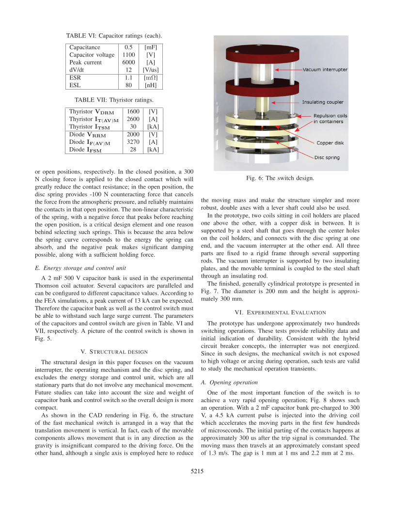
TABLE VI: Capacitor ratings (each).
Capacitance 0.5 [mF]
Capacitor voltage 1100 [V]
Peak current 6000 [A]
dV/dt 12 [V/us]
ESR 1.1 [mΩ]ESL 80 [nH]
TABLE VII: Thyristor ratings.
Thyristor VDRM 1600 [V]
Thyristor IT(AV)M 2600 [A]
Thyristor ITSM 30 [kA]
Diode VRRM 2000 [V]
Diode IF(AV)M 3270 [A]
Diode IFSM 28 [kA]
or open positions, respectively. In the closed position, a 300
N closing force is applied to the closed contact which will
greatly reduce the contact resistance; in the open position, the
disc spring provides -100 N counteracting force that cancels
the force from the atmospheric pressure, and reliably maintains
the contacts in that open position. The non-linear characteristic
of the spring, with a negative force that peaks before reaching
the open position, is a critical design element and one reason
behind selecting such springs. This is because the area below
the spring curve corresponds to the energy the spring can
absorb, and the negative peak makes significant damping
possible, along with a sufficient holding force.
E. Energy storage and control unit
A 2 mF 500 V capacitor bank is used in the experimental
Thomson coil actuator. Several capacitors are paralleled and
can be configured to different capacitance values. According to
the FEA simulations, a peak current of 13 kA can be expected.
Therefore the capacitor bank as well as the control switch must
be able to withstand such large surge current. The parameters
of the capacitors and control switch are given in Table. VI and
VII, respectively. A picture of the control switch is shown in
Fig. 5.
V. STRUCTURAL DESIGN
The structural design in this paper focuses on the vacuum
interrupter, the operating mechanism and the disc spring, and
excludes the energy storage and control unit, which are all
stationary parts that do not involve any mechanical movement.
Future studies can take into account the size and weight of
capacitor bank and control switch so the overall design is more
compact.
As shown in the CAD rendering in Fig. 6, the structure
of the fast mechanical switch is arranged in a way that the
translation movement is vertical. In fact, each of the movable
components allows movement that is in any direction as the
gravity is insignificant compared to the driving force. On the
other hand, although a single axis is employed here to reduce
Fig. 6: The switch design.
the moving mass and make the structure simpler and more
robust, double axes with a lever shaft could also be used.
In the prototype, two coils sitting in coil holders are placed
one above the other, with a copper disk in between. It is
supported by a steel shaft that goes through the center holes
on the coil holders, and connects with the disc spring at one
end, and the vacuum interrupter at the other end. All three
parts are fixed to a rigid frame through several supporting
rods. The vacuum interrupter is supported by two insulating
plates, and the movable terminal is coupled to the steel shaft
through an insulating rod.
The finished, generally cylindrical prototype is presented in
Fig. 7. The diameter is 200 mm and the height is approxi-
mately 300 mm.
VI. EXPERIMENTAL EVALUATION
The prototype has undergone approximately two hundreds
switching operations. These tests provide reliability data and
initial indication of durability. Consistent with the hybrid
circuit breaker concepts, the interrupter was not energized.
Since in such designs, the mechanical switch is not exposed
to high voltage or arcing during operation, such tests are valid
to study the mechanical operation transients.
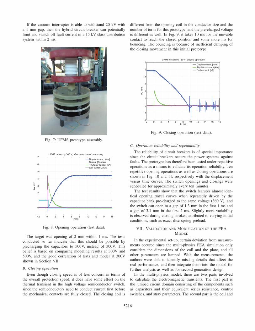
A. Opening operation
One of the most important function of the switch is to
achieve a very rapid opening operation; Fig. 8 shows such
an operation. With a 2 mF capacitor bank pre-charged to 300
V, a 4.5 kA current pulse is injected into the driving coil
which accelerates the moving parts in the first few hundreds
of microseconds. The initial parting of the contacts happens at
approximately 300 us after the trip signal is commanded. The
moving mass then travels at an approximately constant speed
of 1.3 m/s. The gap is 1 mm at 1 ms and 2.2 mm at 2 ms.
5215
If the vacuum interrupter is able to withstand 20 kV with
a 1 mm gap, then the hybrid circuit breaker can potentially
limit and switch off fault current in a 15 kV class distribution
system within 2 ms.
Fig. 7: UFMS prototype assembly.
2 0 2 4 6 8 10 12 14 161
0
1
2
3
4
5
6
7UFMS driven by 300 V, after reduction of one spring
t / ms
kA, m
m
Displacement, [mm]Status, [0=open]Thyristor current [kA]Coil current, [kA]
Fig. 8: Opening operation (test data).
The target was opening of 2 mm within 1 ms. The tests
conducted so far indicate that this should be possible by
precharging the capacitors to 500V, instead of 300V. This
belief is based on comparing modeling results at 300V and
500V, and the good correlation of tests and model at 300V
shown in Section VII.
B. Closing operation
Even though closing speed is of less concern in terms of
the overall protection speed, it does have some effect on the
thermal transient in the high voltage semiconductor switch,
since the semiconductors need to conduct current first before
the mechanical contacts are fully closed. The closing coil is
different from the opening coil in the conductor size and the
number of turns for this prototype; and the pre-charged voltage
is different as well. In Fig. 9, it takes 10 ms for the movable
contact to reach the closed position and some more ms for
bouncing. The bouncing is because of inefficient damping of
the closing movement in this initial prototype.
2 0 2 4 6 8 10 12 14 16 182
1
0
1
2
3
4
5
6UFMS driven by 180 V, closing operation
t / ms
kA, m
m
Displacement, [mm]Thyristor current [kA]Coil current, [kA]
Fig. 9: Closing operation (test data).
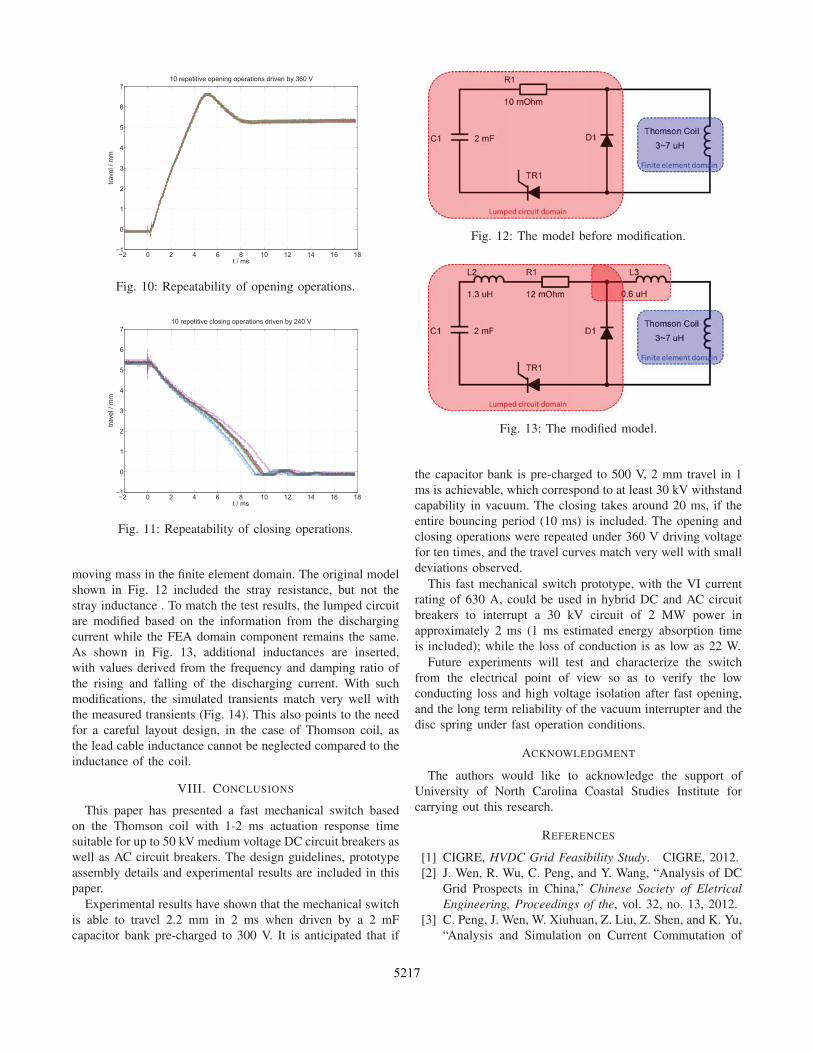
C. Operation reliability and repeatability
The reliability of circuit breakers is of special importance
since the circuit breakers secure the power systems against
faults. The prototype has therefore been tested under repetitive
operations as a means to validate its operation reliability. Ten
repetitive opening operations as well as closing operations are
shown in Fig. 10 and 11, respectively with the displacement
versus time curves. The switch openings and closings were
scheduled for approximately every ten minutes.
The test results show that the switch features almost iden-
tical opening travel curves when repeatedly driven by the
capacitor bank pre-charged to the same voltage (360 V), and
the switch can open to a gap of 1.3 mm in the first 1 ms and
a gap of 3.1 mm in the first 2 ms. Slightly more variability
is observed during closing strokes, attributed to varying initial
conditions, such as exact disc spring preload.
VII. VALIDATION AND MODIFICATION OF THE FEA
MODEL
In the experimental set-up, certain deviation from measure-
ments occured since the multi-physics FEA simulation only
considers the dimensions of the coil and the plate, and all
other parameters are lumped. With the measurements, the
authors were able to identify missing details that affect the
real performance, and then integrate them into the model for
further analysis as well as for second generation design.
In the multi-physics model, there are two parts involved
to calculate the electromagnetic transients. The first part is
the lumped circuit domain consisting of the components such
as capacitors and their equivalent series resistance, control
switches, and stray parameters. The second part is the coil and
5216
2 0 2 4 6 8 10 12 14 16 181
0
1
2
3
4
5
6
710 repetitive opening operations driven by 360 V
t / ms
trave
l / m
m
Fig. 10: Repeatability of opening operations.
2 0 2 4 6 8 10 12 14 16 181
0
1
2
3
4
5
6
710 repetitive closing operations driven by 240 V
t / ms
trave
l / m
m
Fig. 11: Repeatability of closing operations.
moving mass in the finite element domain. The original model
shown in Fig. 12 included the stray resistance, but not the
stray inductance . To match the test results, the lumped circuit
are modified based on the information from the discharging
current while the FEA domain component remains the same.
As shown in Fig. 13, additional inductances are inserted,
with values derived from the frequency and damping ratio of
the rising and falling of the discharging current. With such
modifications, the simulated transients match very well with
the measured transients (Fig. 14). This also points to the need
for a careful layout design, in the case of Thomson coil, as
the lead cable inductance cannot be neglected compared to the
inductance of the coil.
VIII. CONCLUSIONS
This paper has presented a fast mechanical switch based
on the Thomson coil with 1-2 ms actuation response time
suitable for up to 50 kV medium voltage DC circuit breakers as
well as AC circuit breakers. The design guidelines, prototype
assembly details and experimental results are included in this
paper.
Experimental results have shown that the mechanical switch
is able to travel 2.2 mm in 2 ms when driven by a 2 mF
capacitor bank pre-charged to 300 V. It is anticipated that if
Fig. 12: The model before modification.
Fig. 13: The modified model.
the capacitor bank is pre-charged to 500 V, 2 mm travel in 1
ms is achievable, which correspond to at least 30 kV withstand
capability in vacuum. The closing takes around 20 ms, if the
entire bouncing period (10 ms) is included. The opening and
closing operations were repeated under 360 V driving voltage
for ten times, and the travel curves match very well with small
deviations observed.
This fast mechanical switch prototype, with the VI current
rating of 630 A, could be used in hybrid DC and AC circuit
breakers to interrupt a 30 kV circuit of 2 MW power in
approximately 2 ms (1 ms estimated energy absorption time
is included); while the loss of conduction is as low as 22 W.
Future experiments will test and characterize the switch
from the electrical point of view so as to verify the low
conducting loss and high voltage isolation after fast opening,
and the long term reliability of the vacuum interrupter and the
disc spring under fast operation conditions.
ACKNOWLEDGMENT
The authors would like to acknowledge the support of
University of North Carolina Coastal Studies Institute for
carrying out this research.
REFERENCES
[1] CIGRE, HVDC Grid Feasibility Study. CIGRE, 2012.
[2] J. Wen, R. Wu, C. Peng, and Y. Wang, “Analysis of DC
Grid Prospects in China,” Chinese Society of EletricalEngineering, Proceedings of the, vol. 32, no. 13, 2012.
[3] C. Peng, J. Wen, W. Xiuhuan, Z. Liu, Z. Shen, and K. Yu,
“Analysis and Simulation on Current Commutation of
5217

0.2 0 0.2 0.4 0.6 0.8 1 1.2 1.4 1.6 1.8 21
0
1
2
3
4
5
6Measurement and simulation of the transients, driven by 300 V
t / ms
kA, m
m
Measured displacement, [mm]Measured coil current [kA]Simulated displacement, [mm]Simulated coil current, [kA]
Fig. 14: Modified simulation and measured results.
the DC Transfer Switches in UHVDC Transmission Sys-
tems,” Proceedings of the Chinese Society for ElectricalEngineering, vol. 31, no. 36, 2011.
[4] ——, “Development of DC Transfer Switch in Ultra
High Voltage DC Transmission Systems,” Proceedings ofthe Chinese Society for Electrical Engineering, vol. 16,p. 020, 2012.
[5] C. Peng and A. Q. Huang, “A protection scheme against
DC faults VSC based DC systems with bus capacitors,”
in Applied Power Electronics Conference and Exposition(APEC), 2014 Twenty-Ninth Annual IEEE, March 2014,pp. 3423–3428.
[6] J. Hafner and B. Jacobson, “Proactive Hybrid HVDC
Breakers-A key innovation for reliable HVDC grids,”
CIGRE paper, vol. 264, 2011.[7] C. Peng, A. Q. Huang, M. A. Rezaei, X. Huang, and
M. Steurer, “Development of Medium Voltage Solid-
State Fault Isolation Device for Ultra-Fast Protection of
Distribution System,” in The 40th Annual Conference ofthe IEEE Industrial Electronics Society. IEEE, Oct.
2014.
[8] A. Burnett, C. Oates, and C. Davidson, “High voltage dc
circuit breaker apparatus,” Sep. 6 2013, WO Patent App.
PCT/EP2012/053,574.
[9] Y. Wang and R. Marquardt, “Future HVDC-grids em-
ploying modular multilevel converters and hybrid DC-
breakers,” in Power Electronics and Applications (EPE),2013 15th European Conference on, 2013, pp. 1–8.
[10] E. Dong, B. Li, and J. Zou, “Comparison Analysis of
Experiment Performance between high-speed Repulsion
Mechanism and Permanent Magnetic Mechanism,” HighVoltage Apparatus, vol. 43, no. 2, pp. 125–126, 2007.
[11] S. Basu and K. Srivastava, “Analysis of a fast acting
circuit breaker mechanism part i: Electrical aspects,”
Power Apparatus and Systems, IEEE Transactions on,no. 3, pp. 1197–1203, 1972.
[12] ——, “Analysis of a fast acting circuit breaker mecha-
nism, part ii : Thermal and mechanical aspects,” Power
Apparatus and Systems, IEEE Transactions on, vol. PAS-91, no. 3, pp. 1203–1211, May 1972.
[13] R. Rajotte and M. G. Drouet, “Experimental analysis of a
fast acting circuit breaker mechanism: Electrical aspects,”
Power Apparatus and Systems, IEEE Transactions on,vol. 94, no. 1, pp. 89–96, 1975.
[14] Y. Kishida, K. Koyama, H. Sasao, N. Maruyama, and
H. Yamamoto, “Development of the high speed switch
and its application,” in Industry Applications Conference,1998. Thirty-Third IAS Annual Meeting. The 1998 IEEE,vol. 3, Oct 1998, pp. 2321–2328 vol.3.
[15] A. M. S. Atmadji, “Direct current hybrid breakers: A
design and its realization,” Ph.D. dissertation, Technis-
che Universiteit Eindhoven, Eindhoven, The Netherlands,
May 2000.
[16] B. Roodenburg, A. Taffone, E. Gilardi, S. Tenconi,
B. Evenblij, and M. Kaanders, “Combined zvs–zcs topol-
ogy for high-current direct current hybrid switches: de-
sign aspects and first measurements,” Electric PowerApplications, IET, vol. 1, no. 2, pp. 183–192, 2007.
[17] A. Bissal, J. Magnusson, E. Salinas, G. Engdahl, and
A. Eriksson, “On the design of ultra-fast electromechani-
cal actuators: A comprehensive multi-physical simulation
model,” Electromagnetic Field Problems and Applica-tions (ICEF), 2012 Sixth International Conference on,pp. 1–4, June 2012.
[18] V. Puumala and L. Kettunen, “Electromagnetic design
of ultrafast electromechanical switches,” Power Delivery,IEEE Transactions on, vol. 30, no. 3, pp. 1104–1109,June 2015.
[19] C. Peng, I. Husain, and A. Huang, “Evaluation of Design
Variables in Thompson Coil based Operating Mecha-
nisms for Ultra-Fast Opening in Hybrid AC and DC Cir-
cuit Breakers,” in Applied Power Electronics Conferenceand Exposition (APEC), 2015 Thirtieth Annual IEEE,2015.
[20] P. G. Slade, The vacuum interrupter: theory, design, andapplication. CRC press, 2007.
5218