a feasibility study exploring the use of high-pressure ... · array and all electronics can stay...
TRANSCRIPT
1
BNL-98177-2012-IR
A feasibility study exploring the use of high-pressure xenon (HPXe) detectors for the characterization of spent fuel bundles
Vinita J. Ghosh, Aleksey Bolotnikov, Upendra S. Rohatgi
June 2012
Nonproliferation and National Security / Radiation Detector R&D / Building 197C
Brookhaven National Laboratory
U.S. Department of Energy
Office of Nuclear Energy (NE)
Notice: This manuscript has been authored by employees of Brookhaven Science Associates, LLC under Contract No. DE-AC02-98CH10886 with the U.S. Department of Energy. The publisher by accepting the manuscript for publication acknowledges that the United States Government retains a non-exclusive, paid-up, irrevocable, world-wide license to publish or reproduce the published form of this manuscript, or allow others to do so, for United States Government purposes.

2
DISCLAIMER
This report was prepared as an account of work sponsored by an agency of the United States
Government. Neither the United States Government nor any agency thereof, nor any of their
employees, nor any of their contractors, subcontractors, or their employees, makes any warranty,
express or implied, or assumes any legal liability or responsibility for the accuracy, completeness, or any
third party’s use or the results of such use of any information, apparatus, product, or process disclosed,
or represents that its use would not infringe privately owned rights. Reference herein to any specific
commercial product, process, or service by trade name, trademark, manufacturer, or otherwise, does
not necessarily constitute or imply its endorsement, recommendation, or favoring by the United States
Government or any agency thereof or its contractors or subcontractors. The views and opinions of
authors expressed herein do not necessarily state or reflect those of the United States Government or
any agency thereof.
3
BNL-98177-2012-IR
A feasibility study exploring the use of high-pressure xenon (HPXe) detectors for the characterization of spent fuel bundles
Vinita J. Ghosh, Aleksey Bolotnikov, Upendra S. Rohatgi
Brookhaven National Laboratory
May 21, 2012
Executive Summary
As the title suggests we explored the feasibility of using high-pressure xenon detectors for characterizing spent fuel. The three nondestructive characterization techniques currently in use are the Digital Cerenkov Viewing Device, the Fork Detector and the Safeguards Mox Python (SMOPY) Detector. The Fork and SMOPY detectors typically measure the total gamma and total neutron counts due to the gamma emission from fission fragments and the neutron emission originating primarily from curium. Sometimes high-resolution gamma spectroscopy is also used to determine fission-product ratios. These signatures are compared to signatures predicted by the operator declared values of burnup and cooling time, thereby verifying the operator input. The burnup parameters are then used in burnup codes like ORIGEN to calculate the expected mass of 239Pu, 235U and other fissionable materials. These indirect measurement techniques require detailed knowledge of the operating history of the spent fuel assembly in the reactor.
The National Nuclear Security Administration’s Next Generation Safeguards Initiative (NGSI) was launched in 2008. As part of the NGSI initiative a multilab/university collaboration was set up to focus on the direct measurement of the Pu content of spent fuel assemblies using NDA techniques. Currently 14 NDA techniques have been identified for the characterization of spent fuel bundles.
Many of these NDA techniques rely on the measurement of gamma spectra. Currently cadmium zinc telluride (CZT) or high-purity germanium (HPGe) detectors are used for these measurements. The advantages of HPXe detectors over current detectors are that:
1. They can be used for spectroscopy and counting (same as Ge and CZT) 2. The energy resolution (2.0-2.5% at 662 keV and ~1.5% at 1 MeV) is much better than that of
NaI detectors (6-8%). 3. The stopping power is close to that of HPGe, but no cryogenic cooling is required. 4. These detectors are stable and will operate for years. 5. The operational temperature range is broad (15-200 C). 6. There is less neutron activation

4
7. Large-area detectors will not be prohibitively expensive. 8. They are rugged devices for application in harsh high-radiation environments. 9. HPXe is generally used for gamma ray detection but if ~10% 3He is added the xenon
chamber becomes a neutron detector with 100% efficiency for thermal neutrons 10. They operate in ionization (ionization chamber) and scintillation mode (very fast scintillator,
2 ns decay time). 11. Cylindrical HPXe ionization chambers can be made in a variety of shapes and volumes
optimized for particular applications. They can be used as single stand-off gamma-ray detectors or in large-area arrays. Arrays of these detectors can be used in coded aperture imagers.
During this feasibility study we focused our attention on trying to solve two important problems.
(a) Designing a method for the detection of missing fuel rods in spent fuel assemblies. Our proposed feasibility study will explore whether a two-dimensional neutron or gamma detector array can be used in conjunction with appropriate collimators to distinguish between the signatures or patterns associated with gamma or neutron emission from intact spent fuel bundles and bundles with missing fuel rods. The 2D detector array will look down on fuel bundles in spent fuel pools. The advantage of this method is that long collimators can be lowered into the spent fuel pool to reach the top of the fuel assembly whereas the detector array and all electronics can stay out of the water. Minimal handling of the spent fuel bundles will be required. A map or fingerprint of a fuel assembly can be created by these measurements, and a library of fingerprints representing different fuel assemblies can be collected and stored. In order to detect pin diversion, fingerprints of fuel assemblies can be compared before and after transport, or fingerprints of suspect fuel assemblies can be compared with those of intact assemblies. The process can be automated based on pattern recognition/comparison methods. Any suspected variation in the pattern can trigger an alarm and indicate the need for further investigation.
(b) Proposed a new direct method for the determination of the Pu content in spent fuel. A diffracting crystal array will be designed to focus and direct the X- and gamma-rays with specific characteristic energies of 239Pu (60, 414 keV) and 235U (186 keV) onto a small well-shielded gamma detector. All other gamma rays will be transmitted through the diffraction plane, thereby reducing the gamma background at the detector. This approach allows us to select a narrow band of gamma rays from a wide energy spectrum and use very inexpensive, modest energy resolution but high efficiency and small area gamma detectors, e.g., NaI or CZT, located far away from the actual fuel rods. This technique is routinely used for energy selection in neutron scattering and x-ray diffraction instruments. These diffraction devices are often called monochromators. The experimental setup will have to be adapted for the characterization of fuel assemblies in spent fuel tanks.

5
Our goal is to secure funding for the two initiatives outlined above or for the development of HPXe detectors specially configured for spent fuel characterization.
6
A feasibility study exploring the use of high-pressure xenon (HPXe) detectors for the characterization of spent fuel bundles
Table of Contents:
1. Introduction 2. Isotopic composition of spent fuel assemblies 3. Existing technology and recent developments in spent fuel characterization 4. Potential applications of HPXe detectors for spent fuel characterization 5. Detection of missing fuel rods in spent fuel assenmblies 6. Direct measurement of the Pu and U content of spent fuel 7. Summary 8. Acknowledgements 9. References
Appendix 1: Use of gamma and neutron measurements to characterize spent fuel assemblies.
Appendix 2: Review of HPXe detector characteristics
7
1. Introduction
According to the International Atomic Energy Agency (IAEA) approximately 445,000 tHM (tons of heavy metal) will be generated by the world’s commercial nuclear power plants by the year 2020 [1]. This vast inventory of spent fuel will contain a large amount of the world’s plutonium. This spent fuel will need to be stored safely at its current site, moved to reprocessing plants, and/or moved to a geological repository for permanent storage.
Spent fuel is safeguarded by the IAEA using a combination of containment and surveillance measures. IAEA’s safeguards criteria mandate is that partial defect verification (test for pin diversion or substitution) of all spent fuel assemblies has to be performed before they are transported to deep repositories. According to current guidelines these tests should be able to detect the diversion of significant amounts of material or about 50% of the pins.
Spent fuel characterization goals can be summarized as follows:
1. Direct, independent, accurate determination of the Pu content in spent fuel assemblies (to an accuracy of 2%).
2. To detect pin diversion, substitution, or tampering by characterizing a spent fuel assembly prior to and after an event (eg. Transportation to another site) using non-destructive analysis.
If the Pu content of intact fuel assemblies can be measured by some non-destructive analysis (NDA) technique (rather than after chopping and dissolution), it will be much easier to characterize the vast quantities of spent fuel, reconcile shipper/receiver differences, and to estimate the amount of material entering a reprocessing plant or a repository. Improving the detection limits for pin diversion would be significant progress.
Before irradiation reactor fuels can be characterized using passive neutron or gamma spectroscopy (see Appendix 1). However, for irradiated fuel neither passive gamma spectroscopy nor passive neutron signatures can provide direct information about the 235U, 239Pu or 241Pu content. The signatures of these materials are completely masked by the signatures of fission products, transuranic elements (that buildup during the fission process) and activated structural materials. Therefore indirect signatures or signatures of fission products have to be used to estimate the amount of these materials. Active neutron interrogation and self-interrogation neutron resonance densitometry have been used in laboratory settings to estimate the total amount of fissile materials. However, the large-scale deployment of these techniques is not considered practical.
The isotopic composition of spent fuel and the depletion codes used to calculate the isotopic composition are briefly discussed in Section 2. Recent developments in the nondestructive analysis (NDA) of spent fuel, including work done under the Next Generation Safeguards Initiative, have been reviewed very briefly in Section 3. Instead of detailed descriptions a long

8
list of references has been provided. Many of these NDA techniques rely on the measurement of gamma spectra. Currently cadmium zinc telluride (CZT) or high-purity germanium (HPGe) detectors are used for these measurements. We are proposing that high-pressure xenon (HPXe) detectors will be a better alternative to semiconductor detectors.
In section 4 we list the advantages of high-pressure xenon (HPXe) detectors over the CZT or HPGe detectors currently being used for gamma spectroscopy for spent fuel characterization. The major advantages are that HPXe detectors are stable, robust and rugged devices which can operate over a large temperature range (15-200 C) in a high-radiation environment. The energy resolution is comparable to that of CZT detectors but not as good as that of the cryogenically-cooled HPGe. HPXe detectors can be built in a variety of sizes and shapes optimized for special applications, and will be relatively maintenance-free and inexpensive. A historical overview and BNL contributions to this technology are also included in Section 4.
A feasibility study to explore the use of specially-designed two dimensional gamma or neutron detector arrays and collimators to detect missing fuel rods has been outlined in Section 5. A new method for the direct, independent, accurate determination of the Pu content of spent fuel has been described in Section 6. The results of our feasibility study have been summarized in Section 7. For completeness the use of gamma spectroscopy and total neutron count-rates for spent fuel characterization has been briefly reviewed in Appendix 1. Appendix 2 contains more information about HPXe detectors – their operating characteristics and current commercial development.
9
2. Isotopic composition of spent fuel assemblies
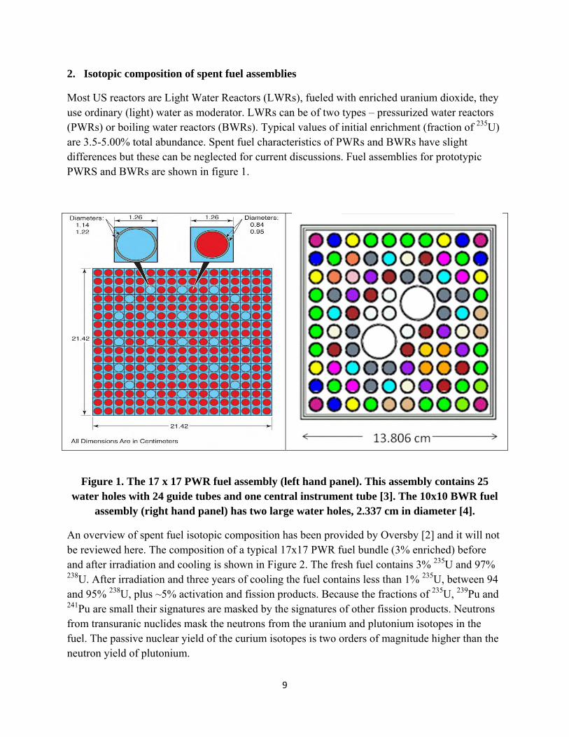
Most US reactors are Light Water Reactors (LWRs), fueled with enriched uranium dioxide, they use ordinary (light) water as moderator. LWRs can be of two types – pressurized water reactors (PWRs) or boiling water reactors (BWRs). Typical values of initial enrichment (fraction of 235U) are 3.5-5.00% total abundance. Spent fuel characteristics of PWRs and BWRs have slight differences but these can be neglected for current discussions. Fuel assemblies for prototypic PWRS and BWRs are shown in figure 1.
Figure 1. The 17 x 17 PWR fuel assembly (left hand panel). This assembly contains 25 water holes with 24 guide tubes and one central instrument tube [3]. The 10x10 BWR fuel
assembly (right hand panel) has two large water holes, 2.337 cm in diameter [4].
An overview of spent fuel isotopic composition has been provided by Oversby [2] and it will not be reviewed here. The composition of a typical 17x17 PWR fuel bundle (3% enriched) before and after irradiation and cooling is shown in Figure 2. The fresh fuel contains 3% 235U and 97% 238U. After irradiation and three years of cooling the fuel contains less than 1% 235U, between 94 and 95% 238U, plus ~5% activation and fission products. Because the fractions of 235U, 239Pu and 241Pu are small their signatures are masked by the signatures of other fission products. Neutrons from transuranic nuclides mask the neutrons from the uranium and plutonium isotopes in the fuel. The passive nuclear yield of the curium isotopes is two orders of magnitude higher than the neutron yield of plutonium.

10
Figure 2. Composition of a typical PWR 17x17 fuel assembly (3% enriched) before and after irradiation [5]. (need reference for this figure)
Before irradiation reactor fuels can be characterized using passive neutron or gamma spectroscopy (see Appendix 1). However, for irradiated fuel neither passive gamma spectroscopy nor passive neutron signatures can provide direct information about the 235U, 239Pu or 241Pu content. The signatures of these materials are completely masked by the signatures of fission products, transuranic elements (that buildup during the fission process) and activated structural materials. Therefore indirect signatures or signatures of fission products have to be used to estimate the amount of these materials. Active neutron interrogation techniques have been used in laboratory settings to estimate the total amount of fissile materials.
The depletion code ORIGEN2 [6] or the improved version ORIGEN-ARP [7], HELIOS [8], and Monteburns [9] can be used to calculate the isotopic composition of spent fuel as a function of the initial enrichment, burnup and cooling time. A literature survey of experimental data on the radiological characteristics of LWR spent fuel has been compiled by Roddy and Mailen [10].

11
Concentrations of 241Am and 243Am calculated with the codes ORIGEN2 [6], HELIOS [8], and Monteburns [9] were compared with experimental data for PWR, BWR and VVER (Russian water-cooled, water-moderated PWRs) spent fuel by Charlton, Stanbro and Perry [11]. The actinide concentrations were determined from radiochemical analyses (alpha and gamma spectroscopy). Burnup was determined from destructive 137Cs and 148Nd analyses (mass spectroscopy). Mass concentrations per metric ton of fuel were calculated for 237Np, 241Am and 243Am. In related work Charlton and Stanbro [12] used signatures like burnup, total Pu concentration, the 240Pu/239Pu isotopic ratio, the 148Nd/238U isotopic ratio and 137Cs activity to determine 237Np, 241Am and 243Am concentrations in spent nuclear fuel. The 237Np, 241Am and 243Am concentrations could be determined to an accuracy of ±4, ±6 and ±15%, respectively. They conclude that these uncertainties can be decreased by improvements in the measurements of these signatures.
An Inverse Depletion/decay code is being developed at ORNL [13] to extract burnup and other reactor parameters from gamma spectroscopy measurements. This code is based on the ORIGEN-ARP forward code [8], the input is gamma spectra or isotopic composition, and the output is parameters like enrichment, power, irradiation time and decay time. This is still a work in progress and requires further development and testing before it is made available to a wide user community. The measured gamma-ray spectrum of a single fuel rod is compared with the calculated spectrum [13] using ORIGEN-ARP in figure 3.
Figure 3. Comparison of the measured gamma-ray spectrum of a single fuel rod with the calculated spectrum using ORIGEN-ARP [13].

12
3. Existing technology and recent developments in spent fuel characterization
The three nondestructive assay techniques currently in use for the characterization of spent fuel assemblies are the Digital Cerenkov Viewing Device [14-16], the Fork Detector [17] and the Safeguards Mox Python (SMOPY) Detector [18].
Gamma-rays from fission and activation products produce electrons that result in the emission of Cerenkov light. A measurement of Cerenkov light can be used as an indicator of the presence of gamma-emitting materials. This indirect method has been used to characterize the spent-fuel assemblies stored under water for a long time [14, 15]. Recent improvements using better electronics and digital images [16] have provided the ability to discriminate between spent-fuel and non-fuel assemblies and to detect pin diversion and/or substitution.
The Fork [17] and SMOPY [18] detectors typically measure the total gamma and total neutron counts due to the gamma emission from fission fragments and the neutron emission originating primarily from curium. Sometimes high-resolution gamma spectroscopy is also used to determine fission-product ratios. These signatures are compared to signatures predicted by the operator declared values of burnup and cooling time, thereby verifying the operator input. These burnup parameters are then used in burnup codes like ORIGEN [7] to calculate the expected mass of 239Pu, 235U and other fissionable materials. These indirect measurement techniques require detailed knowledge of the operating history of the spent fuel assembly in the reactor.
The total gamma-ray activity of submerged fuel assemblies is measured with ion chambers, scintillators, or thermoluminescent dosimeters (TLDs). When the gamma ray activity is measured at the top of the assembly that gamma signal is dominated by the signal of Co-60, Co-58 and Mn-58, the activation products in the structural materials. When the assembly is partially lifted up from the pool, and the detector views the side of the assembly the signal is due primarily to the fission products. From these measurements the values of the operator-declared values for burnup and cooling time can be verified with an accuracy of about 10%. The resulting accuracy in the calculated value of Pu-239 can be calculated and compared to the results of destructive analysis techniques like mass spectrometry.
The total neutron output of irradiated fuel can also be used as an indicator of burnup. A U-235 fission detector is often used because of its insensitivity to gamma rays. Passive neutron measurements have some advantages over gamma measurements. The neutron signal originates in the fuel and the attenuation of the neutron signal is far less than the attenuation of the gamma signal in the fuel assembly. When the neutron detector is placed outside the assembly the neutron response from interior pins is almost as strong as the response from exterior pins. The gamma signal under similar conditions will be dominated by the signal from the exterior pins. However, the attenuation of the neutron signal in water is more severe. The gamma-ray signal decreases by a factor of 10 in 36 cm of water whereas the neutron signal decreases by a factor of 10 in 10 cm of water.
13
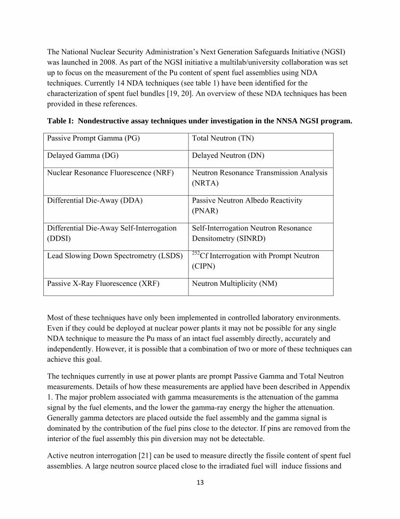
The National Nuclear Security Administration’s Next Generation Safeguards Initiative (NGSI) was launched in 2008. As part of the NGSI initiative a multilab/university collaboration was set up to focus on the measurement of the Pu content of spent fuel assemblies using NDA techniques. Currently 14 NDA techniques (see table 1) have been identified for the characterization of spent fuel bundles [19, 20]. An overview of these NDA techniques has been provided in these references.
Table I: Nondestructive assay techniques under investigation in the NNSA NGSI program.
Passive Prompt Gamma (PG) Total Neutron (TN)
Delayed Gamma (DG) Delayed Neutron (DN)
Nuclear Resonance Fluorescence (NRF) Neutron Resonance Transmission Analysis (NRTA)
Differential Die-Away (DDA) Passive Neutron Albedo Reactivity (PNAR)
Differential Die-Away Self-Interrogation (DDSI)
Self-Interrogation Neutron Resonance Densitometry (SINRD)
Lead Slowing Down Spectrometry (LSDS) 252Cf Interrogation with Prompt Neutron (CIPN)
Passive X-Ray Fluorescence (XRF) Neutron Multiplicity (NM)
Most of these techniques have only been implemented in controlled laboratory environments. Even if they could be deployed at nuclear power plants it may not be possible for any single NDA technique to measure the Pu mass of an intact fuel assembly directly, accurately and independently. However, it is possible that a combination of two or more of these techniques can achieve this goal.
The techniques currently in use at power plants are prompt Passive Gamma and Total Neutron measurements. Details of how these measurements are applied have been described in Appendix 1. The major problem associated with gamma measurements is the attenuation of the gamma signal by the fuel elements, and the lower the gamma-ray energy the higher the attenuation. Generally gamma detectors are placed outside the fuel assembly and the gamma signal is dominated by the contribution of the fuel pins close to the detector. If pins are removed from the interior of the fuel assembly this pin diversion may not be detectable.
Active neutron interrogation [21] can be used to measure directly the fissile content of spent fuel assemblies. A large neutron source placed close to the irradiated fuel will induce fissions and
14
produce a induced fission response proportional to the total fissile mass of U-235, Pu=239 and Pu-241. The neutron source can be an accelerator, a 14MeV neutron generator, or an isotopic source like Cf-252. The strength of the neutron source has to be of the order of 108-109 n/s to produce a fission signal comparable to the passive neutron yield. This method, however does not allow us to differentiate between uranium and plutonium.
Institutions that support the IAEA effort have developed new instrumentation and new procedures to detect pin diversion. One of these instruments is the enhanced Fork Detector (EFDET) which is an improvement on a conventional Fork detector by the addition of a CdZnTe (CZT) detector [22, 23]. Conventional fork detectors measure the total gamma counts and the total neutron counts. The total gamma and neutron signals depend on the total amount of fuel left in the assembly. The neutron signal decreases almost linearly with the number of pins removed from the assembly, independently of which pins are removed. The gamma signal depends on the geometry of the changed assembly. If pins in the row closest to the detector are removed there will be a significant decrease in the gamma signal. However, if the row of pins closest to the detector remains unchanged as many as 50% of the pins may be removed without a significant change in the gamma signal. For short cooling times the gamma spectroscopy data can be used to eliminate the contribution of the short-lived nuclei like Cs-134 and Ru-134/Rh-134. So gamma spectroscopy can refine the estimate of the total gamma count but it does not help detect pin diversion, unless the removed pins lie close to the detector.
To address the problem of pin diversion scientists at LLNL [24] have suggested that neutron and gamma detectors be inserted inside the fuel bundle – in the gaps vacated by control rods or instrumentation tubes. They have calculated the gamma and neutron signals at different locations inside the fuel assembly and compared the calculations with neutron measurements. Simulations and measurements were also performed for assemblies with missing pins. Both gamma and neutron signals in the vicinity of missing pins were different from those for intact assemblies. Neutron measurements for these ‘modified’ assemblies agreed well with the calculated values. The neutron measurements were made with a thin fission detector which is a standard component of the IAEA inventory. A small CZT detector was used for one gamma measurement. The LLNL group is building a device to insert detectors into the fuel assembly from the top.
Another promising technique being developed at LANL is called Self-interrogation Neutron resonance Densitometry (SINRD) [25]. Experiments with fresh fuel agree well with MCNPX [26] simulation results. Experiments with spent fuel have not yet been done.

15
4. Potential applications of HPXe detectors for spent fuel characterization.
Gamma spectroscopy is an important component of the spent fuel characterization suite of techniques and robust, stable gamma ray detectors that can operate without much maintenance in high-radiation, high-temperature environments are needed. Generally NaI(Tl), CdZnTe, LaBr3 and HPGe are used for gamma spectroscopy. The IAEA enhanced Fork Detector (EFDET) which is an improvement on a conventional Fork detector uses a CdZnTe (CZT) detector for gamma spectroscopy [22, 23]. In order to collect well characterized gamma spectra for individual fuel rods HPGe detectors have been used at ORNL [13]. HPGe detectors are expensive and they need cryogenic cooling. These devices also suffer from damage in high-radiation environments.
High pressure xenon detectors (HPXe) are an attractive alternative for room-temperature gamma-ray detectors. The additional advantage is that these detectors can also be used for the detection of fast as well as thermal neutrons. Experiments have shown that the addition of a small percentage of 3He turns xenon detectors into efficient thermal neutron detectors (see reference 27 for details). The high cost and shortage of 3He requires that we actively explore alternate methods for thermal neutron detection. The addition of a few percent 3He to a xenon detector rather than 100% 3He will help extend precious 3He resources. HPXe is a proven technology with detectors currently operating in the MIR space station, Russian nuclear reactors, and at BNL.
The advantages of HPXe detectors over current detectors are that:
1. They can be used for spectroscopy and counting (same as Ge and CZT) 2. The energy resolution (2.0-2.5% at 662 keV and ~1.5% at 1 MeV) is much better than
that of NaI detectors (6-8%). 3. The stopping power is close to that of HPGe, but no cryogenic cooling is required. 4. These detectors are stable and will operate for years. 5. The operational temperature range is broad (15-200 C). 6. There is less neutron activation 7. Large-area detectors will not be prohibitively expensive. 8. They are rugged devices for application in harsh environments (high-radiation, high-
temperature, etc.) 9. HPXe is generally used for gamma ray detection but if ~10% 3He is added the xenon
chamber becomes a neutron detector with 100% efficiency for thermal neutrons 10. They operate in ionization (ionization chamber) and scintillation mode (very fast
scintillator, 2 ns decay time). 11. Cylindrical HPXe ionization chambers can be made in a variety of shapes and volumes
optimized for particular applications. They can be used as single stand-off gamma-ray detectors (energy resolution <2% FWHM at 662 keV and <1.4% at energies greater than 1 MeV) or in large-area arrays.

16
Historical overview of xenon detectors
Research on high pressure xenon gamma spectrometers was pioneered by scientists at Brookhaven National Laboratory (BNL), the NASA Marshal Flight Center and the Moscow Engineering and Physics Institute (MEPhI), Russia. While BNL was working on the parallel-plate ionization chamber, the novel design of the large-volume coaxial ionization chambers with a cylindrical mesh served as the Frisch-grid were developed at NASA. The energy resolution achieved with these detectors was in the range 2.0-2.5% FWHM at 662 keV. The resolution of 1.9% was demonstrated with a small, ~0.5 l chamber and ~2.5% with a 2 l chamber. The design of this chamber was later adopted by MEPhI for the large-volume stand-off detectors.
The technology developed by MEPhI, BNL, and Marshall was eventually transferred to the US by Constellation Technology Corporation, Inc. (CTC). The company obtained some of the designs and prototypes of the detectors built with a coaxial geometry at MEPhI. Unfortunately, the modifications introduced by the CTC engineers into the original design of the chamber and electronics degraded the energy resolution of the detectors. There are several critical factors that can degrade the energy resolution.
BNL scientists working in collaboration with CTC identified several problems for the CTC detectors.
1. The purity of the Xe gas was degraded by the chamber preparation and cleaning before the filling. Stringent chamber preparation and cleaning criteria are required.
2. Electronic noise was caused by the high-voltage power supply. 3. The geometry of the electrodes probably caused the excessive electrical capacitance that was
seen by the front-end electronics. 4. Acoustic noise also contributed to the excessive capacitance.
BNL has proposed several improvements to the CTC detectors in order to overcome these problems. These include:
Development of rigorous procedures to be followed during device cleaning and filling with Xe.
A xenon purification and filling facility has been built at BNL.
Use of a better high-voltage power supply.
Use the new multi-anode (or segmented anode) design, which was developed to improve the energy resolution and drastically reduce the sensitivity to acoustic noise of the current large-volume HPXe ionization chambers. The new design also allows the measurement of the coordinates of interaction points thereby providing position sensitivity.
HPXe is a relatively old technology but it is not widely used in industry. Partially, this is because many potential users do not have much information about the advantages of this technique. Another reason is that, in general, HPXe detectors do not have a wide application area. The third

17
reason is that there are not many experts who really have a detailed knowledge of this detector technology. Fortunately a number of world-leading experts work at BNL.
Xe advantages and application areas.
The development and properties of xenon detectors have been described in detail in references 28-43, and summarized in Appendix 2.
To identify a niche for the large-volume HPXe ionization chambers we will compare them with other gamma-ray detectors. Historically, two types of gamma-ray detectors have been considered for detection and spectroscopy of SNM: semiconductors (Ge, CZT) and scintillators (NaI, CsI). The advantages and disadvantages of these techniques are well known. Room temperature semiconductor detectors, CZT or HgI2, are used for the detection of low-energy gamma rays. Large area (>100 cm2) CZT or HgI2 arrays are required for the detection of shielded or weak SNM. Because of crystal size limitations CZT or HgI2 arrays will be very complex and cost-ineffective. Ge detectors have the best energy resolution and can have larger active volumes but they are very expensive and require cryogenic cooling. Scintillation detectors have the advantage of ambient-temperature operation, relatively low cost per unit of mass, and are available in large volumes. However, large-size crystals are fragile, they have poor energy resolution, and they are sensitive to temperature variations.
The large area (~m2) arrays (panels) of HPXe cylindrical ionization chambers (tubes) have been proposed for use in portal monitors. Such panels will provide high detection efficiency for increased system sensitivity, and the high energy resolution required for the identification of most radioactive sources. HPXe tubes have demonstrated ruggedness and long-term stability comparable to plastic scintillators and to operate for years without maintenance and servicing. They have lower production and operational costs than any other ambient temperature operation detector with comparable energy resolution and potentially large sensitive volumes. HPXe detectors are the ideal technology for the detection of SNM.
BNL contribution
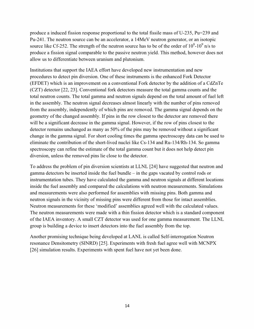
BNL has world class capabilities to develop all types of gaseous detectors including high-pressure Xe devices. The Instrumentation Division at BNL has a long history of developing HPXe parallel-plate ionization chambers and readout electronics. The HPXe chamber built at BNL by G. Smith, et. al. [44] is shown in Figure 4 (Left hand side) and the portable spectrometer based on this chamber is shown on the far right hand side. It is a parallel plate detector, and the xenon density in the chamber is 0.5g/cc, the active volume is 0.5 liters, and the energy resolution is better than 2%. This chamber has been in operation for 12 years.
18
Figure 4. The parallel plate ionization chamber developed at BNL by Graham Smith.
The possible designs of HPXe tube are well described in the literature. Several industrial vendors are in position to fabricate parts and vessels for HPXe detectors, but do not stock commercially available filled tubes. The technology for noble gas purification is also well understood. However, facilities and procedures for filling large numbers of tubes with purified Xe required for the production of square meter sized arrays for primary portal detection have not been developed. This was a critical obstacle that prevented the production of large area HPXe panels.
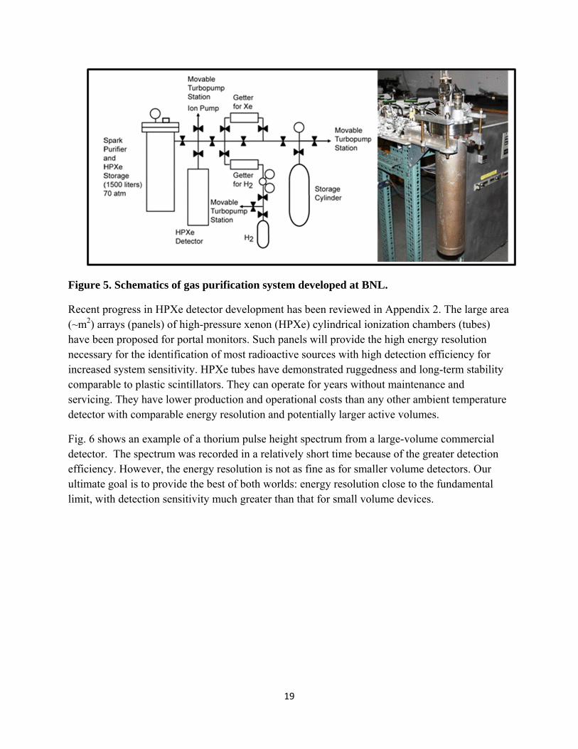
To facilitate the construction of large numbers of HPXe detectors BNL was tasked to establish a facility for the purification and handling of noble gases (e.g., Xe, Ar, Ne, and He-3) and to develop reliable methods, technology and standards for filling a large number of HPXe tubes and other noble gas detectors. The facility includes three major components: (1) a system for the preliminary purification of Xe and other noble gases (oxisorb, high-temperature getter and molecular sieve), (2) a system for the fine purification of Xe (titanium spark purifier) and detector filling, and (3) a cryogenic pump down/vacuum station to prepare tubes for filling. The titanium spark purifier coupled with the pump station forms a single HPXe purification/handling unit. Each unit can be used to fill HPXe tubes with a productivity of up to eight tubes per month. The system capacity may be increased by adding more gas purification/handling units. Figure 5 shows a schematic of gas purification system developed at BNL.
19
Figure 5. Schematics of gas purification system developed at BNL.
Recent progress in HPXe detector development has been reviewed in Appendix 2. The large area (~m2) arrays (panels) of high-pressure xenon (HPXe) cylindrical ionization chambers (tubes) have been proposed for portal monitors. Such panels will provide the high energy resolution necessary for the identification of most radioactive sources with high detection efficiency for increased system sensitivity. HPXe tubes have demonstrated ruggedness and long-term stability comparable to plastic scintillators. They can operate for years without maintenance and servicing. They have lower production and operational costs than any other ambient temperature detector with comparable energy resolution and potentially larger active volumes.
Fig. 6 shows an example of a thorium pulse height spectrum from a large-volume commercial detector. The spectrum was recorded in a relatively short time because of the greater detection efficiency. However, the energy resolution is not as fine as for smaller volume detectors. Our ultimate goal is to provide the best of both worlds: energy resolution close to the fundamental limit, with detection sensitivity much greater than that for small volume devices.

20
Fig. 6. Example of pulse-height spectrum from thorium measured with a large volume, commercial cylindrical ionization chamber.
BNL has proposed a new design for coaxial ionization chambers. The performance parameters are expected to be 2.5% FWHM at 662 keV and <1.5% at > 1 MeV. These performance levels have already been demonstrated with small prototypes. The big detectors (~5-10 l) developed by MEPhI has <3% FWHM at 662 keV. This increase is due to larger electrical capacitance of these detectors. Anode segmentation seems to be the simplest and straightforward solution for this problem. Further progress can be made by the use of better designs for detectors and electronics.
The novel BNL design uses a segmented anode. The multi-anode (or segmented anode) design improves the energy resolution and drastically reduces sensitivity to acoustic noise for large volume HPXe ionization chambers. Currently HPXe cylindrical ionization chambers employ a single-anode electrode (tube) located in the center of the cylindrical chamber. The anode is mounted inside a cylindrical vessel and connected via a high-pressure feedthrough to the preamplifier located outside. This increases the capacitance and electronic noise. For a typical chamber with a length of ~50 cm and a diameter of 12 cm, the anode diameter (1-2 cm) is large. As a result, it has a large electrical capacitance (>50 pF) which makes it difficult to maintain low electronic noise and stability in the presence of mechanical and acoustical vibrations.
The new design also enables the measurement of the coordinates of interaction points, thereby providing position sensitivity. Arrays of such detectors can be used in coded aperture imagers.

21
5. Detection of missing fuel rods in spent fuel assemblies
The techniques currently in use at power plants are prompt Passive Gamma and Total Neutron measurements using the enhanced Fork Detector (EFDET) which also measures the gamma spectrum with a CdZnTe (CZT) detector [12, 13]. Figure 7 is a schematic showing how FORK detectors are used for making measurements in a spent fuel pool [45]. The spent fuel assembly is partially lifted up from the pool and viewed from the sides. The neutron and gamma signals are due primarily to the fission products. From these measurements the values of the operator-declared values for burnup and cooling time can be verified with an accuracy of about 10%. These burnup parameters are then used in burn-up codes like ORIGEN [7] to calculate the expected mass of 239Pu, 235U and other fissionable materials.
The gamma signal under these conditions is dominated by the signal from the exterior pins. If pins in the row closest to the detector are removed there will be a significant decrease in the gamma signal. However, if the row of pins closest to the detector remains unchanged as many as 50% of the pins may be removed from the interior of the assembly without a significant change in the gamma signal. It would be useful to develop a characterization technique that can improve on these statistics.
Figure 7. Schematic showing the use of FORK detectors to make measurements in spent fuel pools [45].

22
Our proposed feasibility study will explore whether a two-dimensional neutron or gamma detector array can be used in conjunction with appropriate collimators to distinguish between the signatures or patterns associated with gamma or neutron emission from intact spent fuel bundles and bundles with missing fuel rods. The 2D detector array will look down on fuel bundles in spent fuel pools as shown in Figure 8. The advantage of this method is that long collimators can be lowered into the spent fuel pool to reach the top of the fuel assembly whereas the detector array and all electronics can stay out of the water. Minimal handling of the spent fuel bundles will be required, which is a distinct advantage.
A map or fingerprint of a fuel assembly can be created by these measurements, and a library of fingerprints representing different fuel assemblies can be collected and stored. In order to detect pin diversion, fingerprints of fuel assemblies can be compared before and after transport, or fingerprints of suspect fuel assemblies can be compared with those of intact assemblies. The process can be automated based on pattern recognition/comparison methods. Any suspected variation in the pattern can trigger an alarm and indicate the need for further investigation. If experimental data indicate that intact assemblies of a particular type have similar general characteristics or maps, then there may not be a need to do extensive searches, and any departure from these general characteristics will indicate tampering.
Figure 8. Experimental setup – not to scale
The simulation plan is to create an idealized spent fuel assembly (similar to the BWR 10x10 fuel assembly shown in figure 9, but with identical fuel rods using SCALE/ORIGEN calculations [8]. This neutron and gamma ray source will be used to develop the collimator design. Simulations of the fuel bundle + collimator + detector array setup (illustrated in figure 7) will be performed using MCNP [26] to predict the output of the neutron and gamma detector arrays. The simulations will be repeated for fuel bundles with missing fuel rods.
23
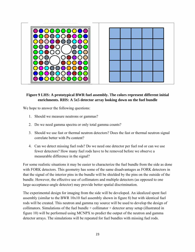
Figure 9 LHS: A prototypical BWR fuel assembly. The colors represent different initial enrichments. RHS: A 5x5 detector array looking down on the fuel bundle
We hope to answer the following questions:
1. Should we measure neutrons or gammas?
2. Do we need gamma spectra or only total gamma counts?
3. Should we use fast or thermal neutron detectors? Does the fast or thermal neutron signal correlate better with Pu content?
4. Can we detect missing fuel rods? Do we need one detector per fuel rod or can we use fewer detectors? How many fuel rods have to be removed before we observe a measurable difference in the signal?
For some realistic situations it may be easier to characterize the fuel bundle from the side as done with FORK detectors. This geometry has some of the same disadvantages as FORK detectors in that the signal of the interior pins in the bundle will be shielded by the pins on the outside of the bundle. However, the effective use of collimators and multiple detectors (as opposed to one large-acceptance-angle detector) may provide better spatial discrimination.
The experimental design for imaging from the side will be developed. An idealized spent fuel assembly (similar to the BWR 10x10 fuel assembly shown in figure 8) but with identical fuel rods will be created. This neutron and gamma ray source will be used to develop the design of collimators. Simulations of the fuel bundle + collimator + detector array setup (illustrated in figure 10) will be performed using MCNPX to predict the output of the neutron and gamma detector arrays. The simulations will be repeated for fuel bundles with missing fuel rods.
24
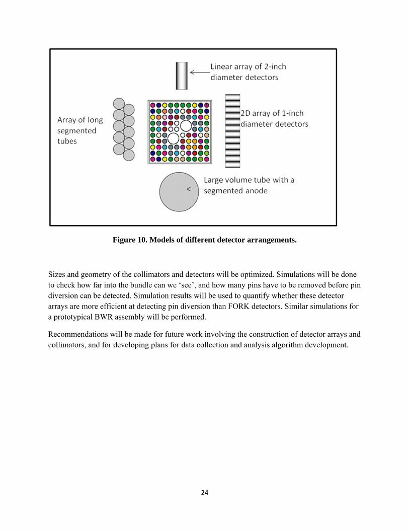
Figure 10. Models of different detector arrangements.
Sizes and geometry of the collimators and detectors will be optimized. Simulations will be done to check how far into the bundle can we ‘see’, and how many pins have to be removed before pin diversion can be detected. Simulation results will be used to quantify whether these detector arrays are more efficient at detecting pin diversion than FORK detectors. Similar simulations for a prototypical BWR assembly will be performed.
Recommendations will be made for future work involving the construction of detector arrays and collimators, and for developing plans for data collection and analysis algorithm development.

25
6. Direct measurement of Pu and U content in spent fuel
The direct, independent, accurate determination of the Pu content in spent fuel is extremely difficult. Currently FORK detectors are used to characterize fuel assemblies [23] by measuring the total neutron and gamma signals of the fuel bundle. These measurements are used to verify the operator declared values of burnup and cooling time, typically with an accuracy of 10%. Codes like ORIGEN [7] are then used with these values of burnup and cooling time to determine the amount of Pu in the assembly.
We have proposed a new direct method for the determination of the Pu content in spent fuel. This technique is routinely used for energy selection in neutron scattering and x-ray diffraction instruments. These diffraction devices are often called monochromators. The experimental setup will have to be adapted for the characterization of fuel assemblies in spent fuel tanks.
A diffracting crystal array will be designed to focus and direct the X- and gamma-rays with specific characteristic energies of 239Pu (60, 414 keV) and 235U (186 keV) onto a small well-shielded gamma detector (see figure 11). All other gamma rays will be transmitted through the diffraction plane, thereby reducing the gamma background at the detector. This approach allows us to select a narrow band of gamma rays from a wide energy spectrum and use very inexpensive, modest energy resolution but high efficiency and small area detectors, e.g., NaI or CZT, located far away from the actual fuel rods.
A similar approach has been recently investigated by a team at ANL in collaboration with ORNL [46]. They use multilayer focusing mirrors for energy selection. However, these mirrors have very narrow acceptance angels at high energies and thus very low efficiency.
We propose to use diffraction crystals operating in transmission (Laue) mode. The gamma energy is related to the lattice spacing of the crystal array by the Bragg equation:
2d sin θBragg = n λ (1)
where the interplanar spacing d is equal to a/(h2 + k2 +l2)1/2. Here, a is the size of the unit cell, θBragg is the Bragg scattering angle, and λ is the photon wavelength. For first order reflections (n=1) and small scattering angles sin θBragg =θBragg and
θBragg = hc/2dE, (2)
where h is Planck’s constant, c the velocity of light and E the photon energy.

26
Figure 11. Experimental setup – not to scale – scattering angles should be very small.
Crystals with appropriate values of d will be selected for individual gamma energy energies. Since the reflectivity of the crystal array can be calculated and/or calibrated, the 239Pu or the 235U content of the spent fuel can be determined from the measured gamma signal. Calculations done for a feasibility study to build a gamma telescope [47] show that copper or germanium crystals have the appropriate lattice parameters and the highest reflectivity for these energies.
The quality and availability of copper or germanium crystals has improved significantly in the last five years. Several techniques have been developed to produce such crystals. Some promising fabrication techniques will be investigated. Collaborations with crystal-growing groups in Europe have already been established and they are ready to send crystals to BNL for characterization at the NSLS. The crystal reflectivity as a function of energy and angle will be measured. A proposal to build and test a prototype array will be submitted once the design has been optimized.
Equipment design and procedures for measuring the Pu content of fuel bundles in a spent fuel pool will be explored and measurement scenarios will be investigated. One option is to mount the diffraction optics system inside a long pipe that can be submerged in the spent fuel pool and placed close to a pin assembly. Measurements near the top of fuel bundle can easily be made using this type of instrument. Facilities where these measurements can be made will be identified and funding requirements for the measurement will be estimated.
27
7. Summary
The three nondestructive assay techniques currently in use for the characterization of spent fuel assemblies are the Digital Cerenkov Viewing Device [14-16], the Fork Detector [17] and the Safeguards Mox Python (SMOPY) Detector [18]. The Fork and SMOPY detectors typically measure the total gamma and total neutron counts due to the gamma emission from fission fragments and the neutron emission originating primarily from curium. Sometimes high-resolution gamma spectroscopy is also used to determine fission-product ratios. These signatures are compared to signatures predicted by the operator declared values of burnup and cooling time, thereby verifying the operator input. These burnup parameters are then used in burnup codes like ORIGEN [7] to calculate the expected mass of 239Pu, 235U and other fissionable materials. These indirect measurement techniques require detailed knowledge of the operating history of the spent fuel assembly in the reactor.
The National Nuclear Security Administration’s Next Generation Safeguards Initiative (NGSI) was launched in 2008. As part of the NGSI initiative a multilab/university collaboration was set up to focus on the measurement of the Pu content of spent fuel assemblies using NDA techniques. Currently 14 NDA techniques (see table 1) have been identified for the characterization of spent fuel bundles [19, 20]. Many of these NDA techniques rely on the measurement of gamma spectra. Currently cadmium zinc telluride (CZT) or high-purity germanium (HPGe) detectors are used for these measurements. We have concluded that high-pressure xenon (HPXe) detectors will be a better alternative.
The advantages of HPXe detectors over current detectors are that:
12. They can be used for spectroscopy and counting (same as Ge and CZT) 13. The energy resolution (2.0-2.5% at 662 keV and ~1.5% at 1 MeV) is much better than that of
NaI detectors (6-8%). 14. The stopping power is close to that of HPGe, but no cryogenic cooling is required. 15. These detectors are stable and will operate for years. 16. The operational temperature range is broad (15-200 C). 17. There is less neutron activation 18. Large-area detectors will not be prohibitively expensive. 19. They are rugged devices for application in harsh environments (high-radiation, high-
temperature, etc.) 20. HPXe is generally used for gamma ray detection but if ~10% 3He is added the xenon
chamber becomes a neutron detector with 100% efficiency for thermal neutrons 21. They operate in ionization (ionization chamber) and scintillation mode (very fast scintillator,
2 ns decay time). 22. Cylindrical HPXe ionization chambers can be made in a variety of shapes and volumes
optimized for particular applications. They can be used as single stand-off gamma-ray detectors or in large-area arrays. An array of such detectors can be used in the coded aperture imagers.
28
During this feasibility study we focused our attention on trying to solve two important problems:
(c) Designing a method for the detection of missing fuel rods in spent fuel assemblies. Our proposed feasibility study will explore whether a two-dimensional neutron or gamma detector array can be used in conjunction with appropriate collimators to distinguish between the signatures or patterns associated with gamma or neutron emission from intact spent fuel bundles and bundles with missing fuel rods. The 2D detector array will look down on fuel bundles in spent fuel pools as shown in Figure 8. The advantage of this method is that long collimators can be lowered into the spent fuel pool to reach the top of the fuel assembly whereas the detector array and all electronics can stay out of the water. Minimal handling of the spent fuel bundles will be required, which is a distinct advantage. A map or fingerprint of a fuel assembly can be created by these measurements, and a library of fingerprints representing different fuel assemblies can be collected and stored. In order to detect pin diversion, fingerprints of fuel assemblies can be compared before and after transport, or fingerprints of suspect fuel assemblies can be compared with those of intact assemblies. The process can be automated based on pattern recognition/comparison methods. Any suspected variation in the pattern can trigger an alarm and indicate the need for further investigation.
(d) Proposed a new direct method for the determination of the Pu content in spent fuel. A diffracting crystal array will be designed to focus and direct the X- and gamma-rays with specific characteristic energies of 239Pu (60, 414 keV) and 235U (186 keV) onto a small well-shielded gamma detector (see figure 11). All other gamma rays will be transmitted through the diffraction plane, thereby reducing the gamma background at the detector. This approach allows us to select a narrow band of gamma rays from a wide energy spectrum and use very inexpensive, modest energy resolution but high efficiency and small area detectors, e.g., NaI or CZT, located far away from the actual fuel rods. This technique has been shown to work in a laboratory setting, but that experimental setup will have to be adapted for measurements of spent fuel bundles in spent fuel tanks.
Our goal is to secure funding for the two initiatives outlined above or for the development of HPXe detectors specially configured for spent fuel characterization.
8. Acknowledgements
The authors would like to thank Mike Todosow, Hans Ludewig and Arnold Aronson for advice and help with spent fuel simulations. We would like to thank DOE-NE for financial support.
29
References
1. Spent Fuel Reprocessing Options, IAEA-TECDOC-1587, IAEA, Vienna, August 2008. 2. Spent fuel characteristics and disposal considerations, V.M. Oversby UCRL-JC-124315,
1996. 3. Spent Fuel Decay Heat Measurements performed at the Swedish central Interim Storage
Facility, B.D. Murphy and I.C. Gauld, U.S.NRC Report NUREG/CR-6971. 4. Nuclear Data Needs for Advanced safeguards – BNL, Michael Todosow, Final Report for
Work Package BN0815040109. 5. Reference for figure 1
6. ORIGEN 2.2 – Isotope Generation and Depletion Code”, ORNL, CCC-371, June 2002. A. Croff, ORNL/TM-7175 (1980). A.G. Croff, ORIGEN2: A versatile computer code for calculating the nuclide compositions and characteristics of nuclear materials, Nuclear Technology vol 62, 335-352, 1980.
7. ORIGEN-ARP 8. Villarino et al. Nucl. Sci. Eng., 112, 16 (1992). 9. User’s manual, Version 1.00 for Monteburns Version 3.01, D. Poston, LA-UR-98-2718
(1998). 10. Radiological Characteristics of light water reactor spent fuel: A literature survey of
Experimental Data, J.W. Roddy and J.C. Mailen, ORNL/TM-10105 11. Comparisons of ORIGEN2, HELIOS, and Monteburns calculated 241Am and 243Am
concentrations to measured values for PWR, BWR and VVER spent fuel, W.S. Charlton, W.D. Stanbro, and R.T. Perry, Journal of Nuclear Science and Technology, vol 37, pages 615-623, 2000.
12. Monitors for the prediction of alternate nuclear material concentrations for pressurized water reactor spent fuel, W.S. Charlton and W.D. Stanbro, Nuclear Technology vol 136, 24-36, 2001.
13. Charles F. Weber, Inverse Problem Analysis Applied to Safeguards Evaluations of Spent Nuclear Fuel, Presented at the Simulations, Algorithms and Modeling Program Review Meeting (SAM2011), ORNL publication ID 28303.
14. J. D. Chen A. F. Gerwing, R. Keeffe, M. Larsson, K. Jansson, L. Hildingsson, B. Lindberg, E. Sundkvist, U. Meijer, M. Thorsell and M. Ohlsson, “Long-Cooled Spent Fuel Verification Using a Digital Cerenkov Viewing Device,” International Atomic Energy Agency Report (IAEA-SM-367/14/07), (2007).
15. E.J. Dowdy, N. Nicholson and T.J. Caldwell, “Irradiated Fuel Monitoring by Cerenkov Glow Intensity Measurements”, LANL report LA-7838-MS (1979).
16. N. Nicholson and E.J. Dowdy, “Irradiated Fuel Examination using the Cerenkov Technique”, LANL report LA-8767-MS (1981).
17. P. M. Rinard and G. E. Bosler, “Safeguarding LWR Spent Fuel with the Fork Detector,” Los Alamos National Laboratory Report (LA-11096-MS), (1988).
30
18. A. Lebrun, M. Merelli, J-L. Szabo, M. Huver, R. Arlt, and J. Arenas-Carrasco, “SMOPY a new NDA tool for safeguards of LEU and MOX spent fuel,” International Atomic Energy Agency Report (IAEA-SM-367/14/03 47), (2003).
19. Veal Overview for INMM2010 20. Stephen J. Tobin, Scot F. Demuth, Mike L. Fensin, John S. Hendricks, Howard O. Menlove,
Martyn T. Swinhoe, Determination of plutonium content in spent fuel with NDA – Why an integrated approach? LA-UR-08-03763
21. Passive Nondestructive Assay of Nuclear Materials, edited by Doug Reilly, Norbert Ensslin and Hastings Smith, Jr. 1991. NUREG/CR-5550, LA-UR-732.
22. A. Titta, J. Saarinen, M. Tarainen, K. Axell, P. Jansson, R. Carchon, J. Gerits, Y. Kulikov and Y.G. Lee, Investigation on the possibility to use Fork Detectors for partial defect verification of spent LWR fuel assemblies, Final report on Task JNT A 1071 (Bel, Fin, Swe) of the member states support programme to IAEA Safeguards, STUK-YTO-TR 191 (September 2002)
23. A. Titta, J. Hautamaki, A. Turunen, R. Arlt, J. Arenas Carrasco, K. Esmailpour-Kazerouni and P. Schwalbach, Spent BWR fuel characterization combining a Fork Detector with Gamma Spectrometry
24. Y.S. Ham, S. Sitaraman, Development of a Safeguards Verification Method and Instrument to Detect Pin Diversion from Pressurized water reactor (PWR) fuel Assemblies. Phase I Study. LLNL Report LLNL-TR-409660 (2009).
25. A.M. LaFleur, W.S. Charlton, H.O. Menlove, M.T. Swinhoe, Comparison of fresh fuel experimental measurements to MCNPX calculations using seld-interrogation neutron resonance densitometry, Nuclear Instruments and Methods in Physics Research A. (2010).
26. MCNP5/MCMPX package C00740MNYCP08, distributed by RSICC at ORNL. 27. Detection of thermal neutrons in cylindrical ionization chamber filled with high-pressure
Xe+3He gas mixture A. Bolozdynyaa,*, A. Bolotnikovb, J. Richardsa, A. Proctora, Nuclear Instruments and Methods in Physics research. A 522 (2004) 595-597.
28. A.E.Bolotnikov, V.V.Dmitrenko, A.S.Romanuk, S.I.Suchkov and Z.M.Uteshev, Pribory I Tekhnika Eksperimenta, Vol.29, p.42 (1986) (USSR). Translation in Instrum.& Exp.Tech. (USA), Vol.29, p.802 (1986).
29. A.E.Bolotnikov, V.V.Dmitrenko, A.S.Romanuk, S.I.Suchkov and Z.M.Uteshev Z.M., Journal of Technical Physics (USSR), Vol.58, p.734 (1988). Translation in Sov. Phys.-Technical Phys. (USA), Vol.33, p.449 (1988)
30. I.M.Obodovski, S.G.Pokachalov, V.A. Shilov, Journal of Technical Physics (USSR), 50, 2028-2030 (1980).
31. V.V. Dmitrenko, A.S.Romanuk, S.I.Suchkov, and Z.M.Uteshev, Journal of Technical Physics (USSR), Vol.53, p.2343 (1983). Translation in Sov. Phys.-Technical Phys. (USA), 28,1440 (1983).
32. T. Doke, Portugal Phys. Vol.12, p.9 (1981). 33. E.Aprile, R.Mukherjee, and M.Suzuki, Nucl. Instrum. & Methods Vol. A302, p.177 (1991).
31
34. Bolotnikov and B. Ramsey, “Improving the Energy Resolution of High-pressure Xe Cylindrical Ionization Chambers”, IEEE Tras. Nucl. Sci., NS 44, pp. 1006-1010, 1997.
35. Bolotnikov and B. Ramsey, “ Purification techniques and purity and density measurements of high-pressure Xe”, Nucl. Instr. Meth. A v. 383 (1996) 619-623
36. C.Levin, J.Germani and J.Markey, Nucl. Instrum. & Methods, Vol. A332, pp.206-214 (1993).
37. V.V. Dmitrenko et al. “Vibrostability of High Pressure Xenon Gamma-Ray Detectors”, IEEE Trans. Nucl. Sci., v.47, n.3, pp.939-943, 2000
38. V.V. Dmitrenko et al. “A Thermostable High Pressure Xenon Gamma-Ray Detector for Monitoring Concentration of KCl during Fertilizer Manufacturing”, Nucl. Intrum. and Methods in Physics Research, v. A422, pp.326-330, 1999.
39. S. E. Ulin et al. “Influence of Proton and Neutron Fluxes on Spectrometric Characteristics of High Pressure Xenon Gamma-Spectrometer”, Proc. SPIE v.3114, pp.499-504, 1997.
40. G. Tepper, J. Losee, R. Palmer, “A cylindrical xenon ionization chamber detector for high resolution, room temperature gamma radiation spectroscopy”, Nucl Instr. And Meth. A 413, pp.467-470, 1998
41. G.F. Knoll, Radiation Detection and Measurements, 3rd edition, John Wiley & Sons, 2000. P.148-155.
42. A. Bolotnikov and B. Ramsey, “The spectroscopic properties of high pressure xenon”, Nucl. Instr. Meth. A v.396 (1997) 360-370
43. Bolozdynya et al., “High pressure xenon electronically collimated camera for low energy gamma ray imaging”, IEEE Trans. Nucl. Sci., v.44, n.6 (1997) 2408-2414.
44. G.J. Mahler, B. Yu, G.C. Smith, W.R. Kane and J.R. Lemley, “A portable gamma-ray spectrometer using compressed xenon,” IEEE Trans. Nucl. Sci. NS-45 (1998) 1029-1033. BNL Report BNL-64949.
45. Review of Information for Spent Nuclear Fuel Burnup Confirmation, NUREG/CR-6998. 46. Michael Pivovaroff, Direct measurement of U235 and Pu239 in spent fuel rods with gamma-
ray mirrors, Presented at the SNM Movement Detection / Radiation Detectors and Advanced Materials Program Review Meeting (RadSensing 2011).
47. A gamma-focusing telescope for long-range detection of nuclear materials: A feasibility study, Dr. A. Bolotnikov, Dr. V. Ghosh, Dr. W. Kane and Dr. L. Passel, Final project report submitted to NA22 (2006).
48. Fundamentals of Passive Nondestructive Assay of Fissionable Material, H.R. Auguston and T.D. Reilly, 1974. LA-561-M.
32
Appendix 1
The use of passive gamma spectroscopy and total neutron count-rates for spent fuel characterization
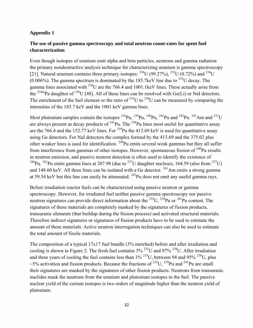
Even though isotopes of uranium emit alpha and beta particles, neutrons and gamma radiation the primary nondestructive analysis technique for characterizing uranium is gamma spectroscopy [21]. Natural uranium contains three primary isotopes: 238U (99.27%), 235U (0.72%) and 234U (0.006%). The gamma spectrum is dominated by the 185.7keV line due to 235U decay. The gamma lines associated with 238U are the 766.4 and 1001.1keV lines. These actually arise from the 234mPa daughter of 238U [48]. All of these lines can be resolved with Ge(Li) or NaI detectors. The enrichment of the fuel element or the ratio of 235U to 238U can be measured by comparing the intensities of the 185.7 keV and the 1001 keV gamma lines.
Most plutonium samples contain the isotopes 238Pu, 239Pu, 240Pu, 241Pu and 242Pu. 241Am and 237U are always present as decay products of 241Pu. The 238Pu lines most useful for quantitative assay are the 766.4 and the 152.77 keV lines. For 239Pu the 413.69 keV is used for quantitative assay using Ge detectors. For NaI detectors the complex formed by the 413.69 and the 375.02 plus other weaker lines is used for identification. 240Pu emits several weak gammas but they all suffer from interference from gammas of other isotopes. However, spontaneous fission of 240Pu results in neutron emission, and passive neutron detection is often used to identify the existence of 240Pu. 241Pu emits gamma lines at 207.98 (due to 237U daughter nucleus), 164.59 (also from 237U) and 148.60 keV. All three lines can be isolated with a Ge detector. 241Am emits a strong gamma at 59.54 keV but this line can easily be attenuated. 242Pu does not emit any useful gamma rays.
Before irradiation reactor fuels can be characterized using passive neutron or gamma spectroscopy. However, for irradiated fuel neither passive gamma spectroscopy nor passive neutron signatures can provide direct information about the 235U, 239Pu or 241Pu content. The signatures of these materials are completely masked by the signatures of fission products, transuranic elements (that buildup during the fission process) and activated structural materials. Therefore indirect signatures or signatures of fission products have to be used to estimate the amount of these materials. Active neutron interrogation techniques can also be used to estimate the total amount of fissile materials.
The composition of a typical 17x17 fuel bundle (3% enriched) before and after irradiation and cooling is shown in Figure 2. The fresh fuel contains 3% 235U and 97% 238U. After irradiation and three years of cooling the fuel contains less than 1% 235U, between 94 and 95% 238U, plus ~5% activation and fission products. Because the fractions of 235U, 239Pu and 241Pu are small their signatures are masked by the signatures of other fission products. Neutrons from transuranic nuclides mask the neutrons from the uranium and plutonium isotopes in the fuel. The passive nuclear yield of the curium isotopes is two orders of magnitude higher than the neutron yield of plutonium.

33
The gamma spectrum of a PWR fuel assembly with an exposure or 32GWd/tU and a cooling time of 9 months [21] is shown in figure 1.1. This spectrum contains gamma rays due to fission products as well as gammas from the activation of fuel cladding and structural materials such as 54Mn, 58Co and 60Co.
Figure 1.1. The gamma spectrum of a PWR fuel assembly with an exposure of 32GWd/tU and a cooling time of 9 months [21].
The buildup of specific fission products can be used as a quantitative measure of burnup [ref. 21, Chapter 18]. The measured gamma ray activity I(counts/s) is proportional to the number N of the fission product nuclei formed during irradiation:
I = Є k S N λ e-λT (1)
Where Є = absolute detector efficiency
k = branching ratio
S = attenuation correction
λ = fission product decay rate
T = cooling time.

34
Equation (1) is solved for N and the fuel burnup can be calculated by the equation:
Atomic % burnup = 100 x (N/Y)/U (2)
Where Y = effective fission product yield
U = number of initial uranium atoms.
137Cs is the most widely accepted indicator of burnup. Past experience has shown that the absolute 137Cs activity can determine burnup to an accuracy of 1- 4 % for individual fuel rods. However, 137Cs has identical fission yields from both 235U and 239Pu, so the 137Cs gamma yield can be used to determine the total number of fissions. The gamma output of 106Ru can be used to determine the relative proportion of 239Pu fissions to total fissions.
The burnup of irradiated fuel can also be determined from the ratios of some fission product isotopes. The most commonly known used isotopic ratios are 134Cs/137Cs and 154Eu/137Cs since both these ratios have a fairly linear dependence on burnup. It is easier to determine activity ratios than absolute values of the activity because only relative detector efficiencies need to be known. It would still be necessary to correct for changes in detector efficiency with gamma ray energy.
Operator-declared values of burnup and cooling time can be verified using the gamma-ray activity. The total gamma activity is divided by the declared burnup and is plotted as a function of the declared cooling times. The normalized gamma activity has the form aTb where a and b are scaling parameters and T is the declared cooling time.
The total neutron output of irradiated fuel can also be used as an indicator of burnup. Passive neutron measurements have some advantages over gamma measurements. The neutron signal originates in the fuel and the attenuation of the neutron signal is far less than the attenuation of the gamma signal in the fuel assembly. When the neutron detector is placed outside the assembly the neutron response from interior pins is almost as strong as the response from exterior pins. The gamma signal under similar conditions will be dominated by the signal from the exterior pins. 244Cm and 242Cm are the dominant neutron-emitting isotopes.
For burnup values B exceeding 10 GWd/tU the relationship between the neutron emission rate and burnup can be approximated by a power law:
Neutron rate = α Bβ
For a wide variety of light-water-reactor fuels the value of β is between 3 and 4. Usually both passive gamma and neutron measurements can be made simultaneously. The data can be combined to validate the operator declared values of both exposure and cooling time. The fraction of 235U, 239Pu and 241Pu can then be inferred using well-known codes like ORIGEN [7].

35
Appendix 2
Review of HPXe detector characteristics
HPXe gas has a unique combination of physical properties that make it very attractive as the active medium in different types of nuclear detectors: high stopping power, low Fano-factor, mechanical and chemical stability, and low energy required to produce electron-ion pairs. It is a relatively low cost material (the current market price for high-purity xenon is about $1/g, compared to $50/g for HPGe or $300/g for CZT). In the past, significant efforts have been focused on developing imaging proportional chambers, Compton cameras, luminescence cameras, liquid Xe TPCs, and simple HPXe ionization chambers. Despite the fact that not all of these projects were successful, they resulted in the development of a new detection technique and helped to identify its capabilities and limitations. These detectors have good energy resolution, high detection efficiency and long-term stability. The high reliability of HPXe detectors has been demonstrated in industrial facilities, during field applications (e.g., helicopter-borne systems), and onboard the space station MIR (~10-year operation period). There are no fundamental limitations to the size of HPXe detectors, which may be built in variety of configurations. Large arrays with square meters of detecting area will not be expensive.
The development and properties of xenon detectors have been described in detail in references 33-48, and will be briefly summarized here.
Three important parameters that determine the performance of HPXe detectors are:
Intrinsic energy resolution (determine spectral response)
Electron drift velocity (how fast a detector can be) and
Stopping power (detection efficiency)
In the early 80s, HPXe gas was proposed as an alternative to liquid Xe which had relatively poor energy resolution. Even for HPXe the expected theoretical limit of ~0.6% at 662 keV was achieved only at low densities. The energy resolution was found to degrade at densities above 0.55 g/cc (see figure 2.1).

36
Figure 2.1. Energy resolution at 662 keV plotted as a function of Xe density
However, the energy resolution of the HPXe detectors does not change from room temperature to 200 C (see figure 2.2), which implies that these detectors can be used at high temperatures where other detectors cannot operate. The performance of semiconductor detectors rapidly degrades with temperature.
Figure 2.2. Relative changes of the total collected charge and energy resolution measured at the operational densities of 0.5 g/cc.
The energy spectra measured with high pressure Xe ionization chambers [xxx] developed at Moscow Engineering Physics Institute (MEPhI) are shown in figure 2.3. The spectra show that large volume Xe detectors can resolve both low- and high-energy gamma-ray lines.

37
Figure 2.3. Gamma spectra of Eu-152 and Th-232. Large volume Xe detectors can resolve both low- and high-energy gamma-ray lines.
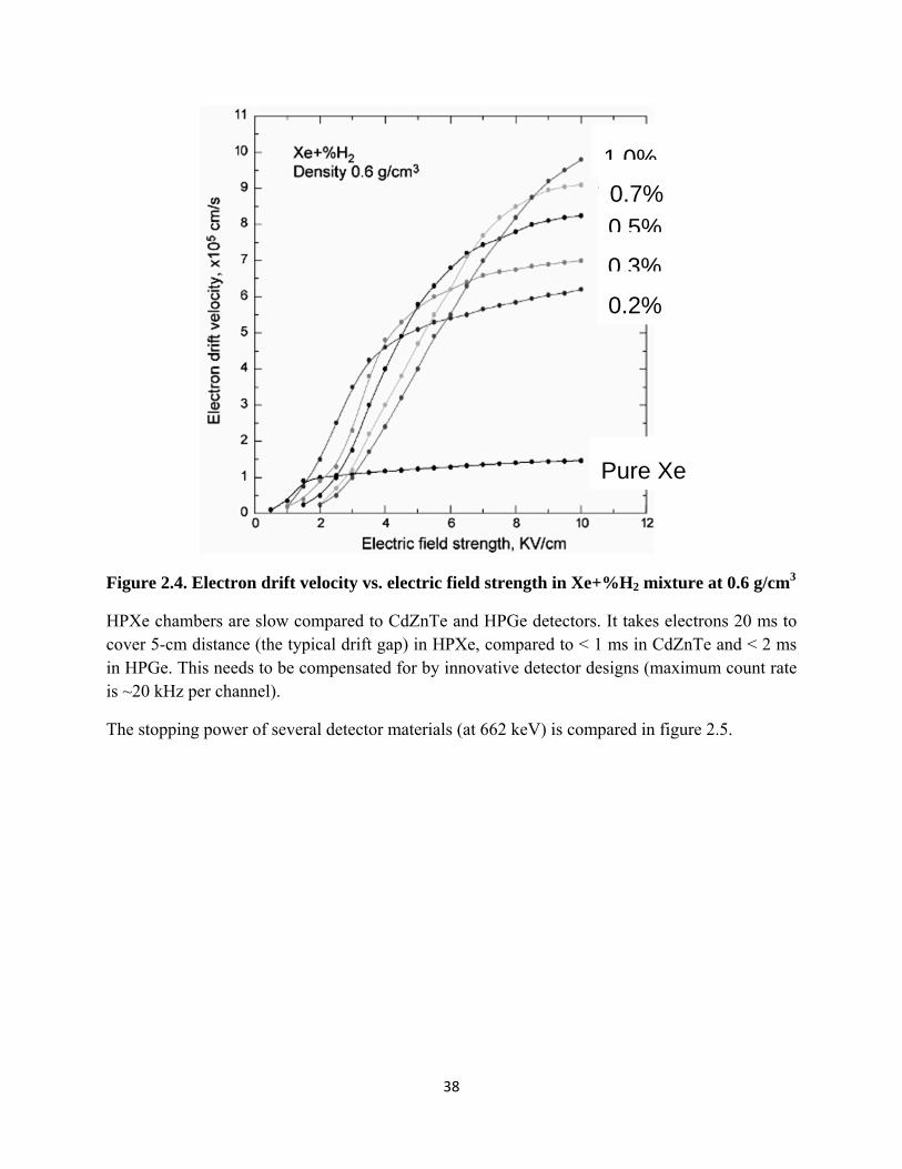
The electron drift velocity determines the charge collection rate and how ‘fast’ the detector is. Electron drift velocity is low in pure Xe and saturates at ~1 mm/ms. Small admixtures of H2, N2, or CH4 increase the velocity by 5-10 times (Ramsauer effect). H2 is the most practical because it can withstand the spark purification required for purifying xenon. The change in the electron drift velocity with the percentage of H2 is plotted in figure 2.4.
38
Figure 2.4. Electron drift velocity vs. electric field strength in Xe+%H2 mixture at 0.6 g/cm3
HPXe chambers are slow compared to CdZnTe and HPGe detectors. It takes electrons 20 ms to cover 5-cm distance (the typical drift gap) in HPXe, compared to < 1 ms in CdZnTe and < 2 ms in HPGe. This needs to be compensated for by innovative detector designs (maximum count rate is ~20 kHz per channel).
The stopping power of several detector materials (at 662 keV) is compared in figure 2.5.
1.0%
0.5%
0.3%
0.2%
Pure Xe
0.7%

39
Figure 2.5. Comparison of the stopping powers of HPXe, CZT and Ge.
A 10-cm layer of Xe at 0.5 g/cc is equivalent to ~1 cm of CZT or LaBr3, ~1.5 cm of NaI(Tl), or ~2 cm of Ge. In order to compensate for the lower stopping power the HPXe detectors have to be larger (volume and/or area) to get the same detection efficiency.
HPXe detectors are a well-developed and ready-to-use technology. However, attention to some critical details is necessary:
Purification of Xe is important, electron lifetime, > 1 ms
Chamber preparation and Xe gas filling procedures have to be carefully implemented
Design constraints associated with high-pressure (~50 atm) and high voltage (20 KV)
Use low-outgas materials (high-density ceramic, SS, Al)
System has a high sensitivity to external noises (electromagnetic and acoustic) due to high capacitances of detector electrodes
All these potential problems have been addressed in the past and have “standard” solutions.
40
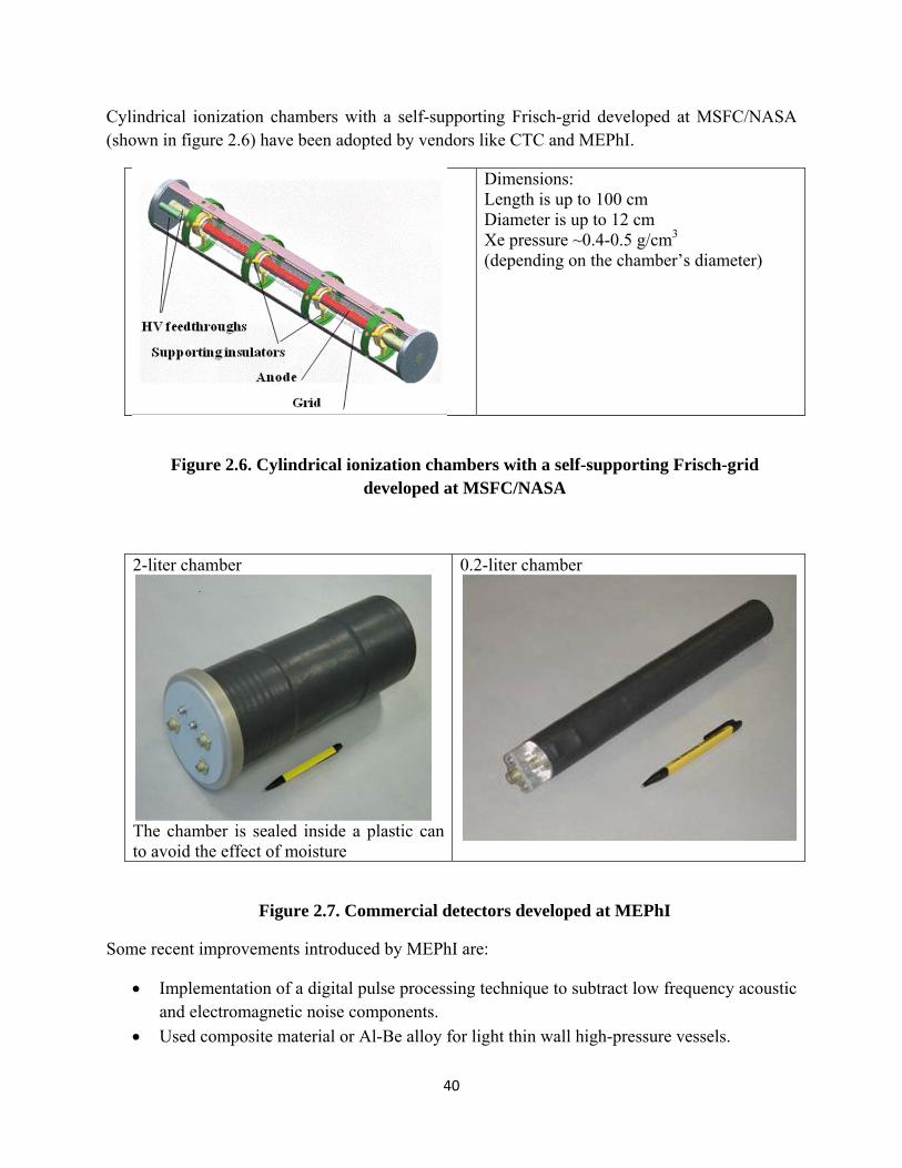
Cylindrical ionization chambers with a self-supporting Frisch-grid developed at MSFC/NASA (shown in figure 2.6) have been adopted by vendors like CTC and MEPhI.
Dimensions: Length is up to 100 cm Diameter is up to 12 cm Xe pressure ~0.4-0.5 g/cm3 (depending on the chamber’s diameter)
Figure 2.6. Cylindrical ionization chambers with a self-supporting Frisch-grid developed at MSFC/NASA
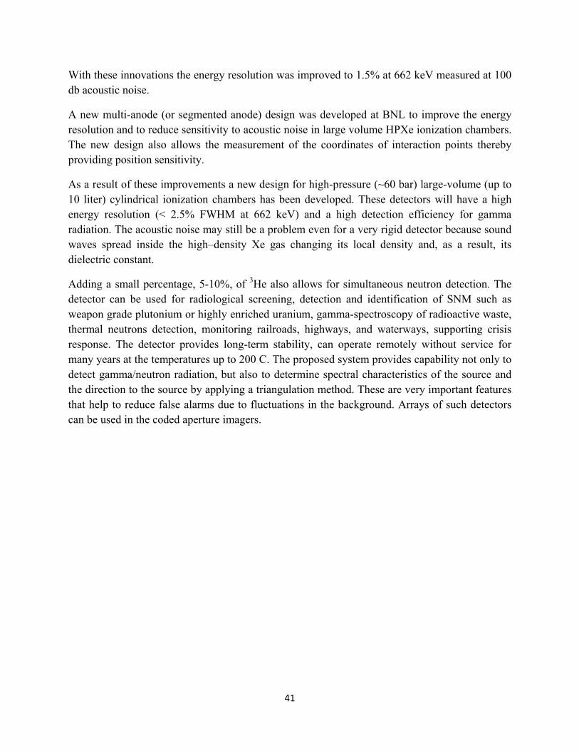
2-liter chamber
The chamber is sealed inside a plastic can to avoid the effect of moisture
0.2-liter chamber
Figure 2.7. Commercial detectors developed at MEPhI
Some recent improvements introduced by MEPhI are:
Implementation of a digital pulse processing technique to subtract low frequency acoustic and electromagnetic noise components.
Used composite material or Al-Be alloy for light thin wall high-pressure vessels.
41
With these innovations the energy resolution was improved to 1.5% at 662 keV measured at 100 db acoustic noise.
A new multi-anode (or segmented anode) design was developed at BNL to improve the energy resolution and to reduce sensitivity to acoustic noise in large volume HPXe ionization chambers. The new design also allows the measurement of the coordinates of interaction points thereby providing position sensitivity.
As a result of these improvements a new design for high-pressure (~60 bar) large-volume (up to 10 liter) cylindrical ionization chambers has been developed. These detectors will have a high energy resolution (< 2.5% FWHM at 662 keV) and a high detection efficiency for gamma radiation. The acoustic noise may still be a problem even for a very rigid detector because sound waves spread inside the high–density Xe gas changing its local density and, as a result, its dielectric constant.
Adding a small percentage, 5-10%, of 3He also allows for simultaneous neutron detection. The detector can be used for radiological screening, detection and identification of SNM such as weapon grade plutonium or highly enriched uranium, gamma-spectroscopy of radioactive waste, thermal neutrons detection, monitoring railroads, highways, and waterways, supporting crisis response. The detector provides long-term stability, can operate remotely without service for many years at the temperatures up to 200 C. The proposed system provides capability not only to detect gamma/neutron radiation, but also to determine spectral characteristics of the source and the direction to the source by applying a triangulation method. These are very important features that help to reduce false alarms due to fluctuations in the background. Arrays of such detectors can be used in the coded aperture imagers.