a functional reasoning cube model for conceptual design of mechatronic systems
TRANSCRIPT
*Corr. Author’s Address: South China University of Technology, School of Mechanical and Automotive Engineering, Guangzhou, China, [email protected] 323
Strojniški vestnik - Journal of Mechanical Engineering 59(2013)5, 323-332 Received for review: 2012-08-27© 2013 Journal of Mechanical Engineering. All rights reserved. Received revised form: 2013-02-14DOI:10.5545/sv-jme.2012.757 Original Scientific Paper Accepted for publication: 2013-02-18
0 INTRODUCTION
In the initial design period, the trial and error method is generally used. However, modern technology systems design must be guided by modern design theory [1] to [4]. Conceptual design is the first stage of engineering design and includes three kinds of processes: functional reasoning, concept solving, and solution synthesizing. Functional reasoning in particular is increasingly regarded as an important technique in engineering [5] to [7]. The essence of functional reasoning is the reasoning process from overall functions to all levels of sub-functions through several sets of nested functional decompositions, in which each functional decomposition generates the next level of sub-functions from a function.
Historically, there are influential functional reasoning approaches or models for conceptual design, such as Freeman and Newells' model [8], the Zigzag model by Suh [9], the Scheme for functional reasoning [10] and [11], the Function logic approach [12], Gero's FBS-model [13], the Function-behavior-state model [14], Function-to-form mapping [15], and the Function-oriented theoretical framework [16]. Each of these models provides a framework to show the reasoning process of the whole. Nevertheless, when these models are applied in actual functional decomposition, a common question naturally arises: how are the lower level sub-functions generated? We believe that the problem is caused by the unclear relationship between the sub-function and the function. Moreover, Garbacz has pointed out that the semantics of the relationship that “x is a sub-function of y” is still unclear [17]. So, functional reasoning largely depends on the inspiration and experience of the designers rather than knowledge.
The systematic model proposed by Pahl and Beitz differs from other functional reasoning approaches. In the model, the relationships between the sub-function and function can be described by flows. Thus the relationships are relatively clear [18]. In the systematic model, the overall function of a technical system is represented by a black-box operation dealing with the flows of materials, energies, and signals at first. This overall function is then progressively expanded into combinations of sub-functions. This combination is called function-structure. This process of simplification is continued until the sub-functions of the function-structure are so simple that each sub-function can be provided by the corresponding scheme (concept solution). However, this model is not perfect either. Firstly, it is difficult to extract (determine) and comprehensively describe all the input and output flows according to the demands of the customers. Secondly, when both the overall function description and sub-function description are included in the three sorts of flows, function decomposition has no definite target. Thus, the same puzzle arises: how are the lower level sub-functions generated?
If the three sorts of flows are separately analyzed, it is only necessary to trace one sort of flow separately during the function decomposition. In this way, the target becomes clear and functional reasoning is simple. Thus, defects in the systematic model are avoided. Based on this strategy, we refine the functional representation and propose how to describe the functions with one sort of flow and then provide three functional reasoning rules. Based on the function description and reasoning rules, we propose a new functional reasoning model named the cube model. The cube model can be regarded as an improved systematic model. An illustrational comparison and discussion showed that the proposed cube model was
A Functional Reasoning Cube Model for Conceptual Design of Mechatronic Systems
Zou, J. – Du, Q.Jiehui Zou* – Qungui Du
South China University of Technology, School of Mechanical and Automotive Engineering, China
In order to improve the conceptual design of mechatronic systems, a refined functional representation aimed at functional reasoning is presented in this paper. Based on the refined functional representation, we proposed a cube model for functional reasoning. We compared the cube model with the systematic model through an illustration. The cube model can be regarded as an improvement of the systematic model. In addition, the application scope of the cube model is discussed. The proposed cube model can be applied to design other systems (except holonomic mechatronic systems). Illustrational comparison and discussion showed that the proposed cube model was clear and easy to use for designing various technical systems.Keywords: cube model, refined functional representation, functional reasoning, design process, conceptual design, engineering design

Strojniški vestnik - Journal of Mechanical Engineering 59(2013)5, 323-332
324 Zou, J. – Du, Q.
clear and easy to use for designing various technical systems. The paper’s structure was inspired by the work of Chakrabarti and Bligh [10].
1 A REFINED FUNCTIONAL REPRESENTATION
The essence of conceptual design is to describe the design problem as an intended function and find a physical solution to provide it. Therefore, function is crucial to conceptual design and functional representation is a precondition of the functional reasoning model. However, there is still no consensus about the meaning of the term “function” itself in engineering [7] and [19] to [22].
1.1 Refining the Flows
It is well-known that there are three sorts of flows: material flows, energy flows, and information flows. Pahl and Beitz believed that the function could be described by changes in the energy, material and information flows (hereafter respectively E_flow, M_flow, and I_flow for short). Thus, this functional representation comprises three sorts of flows, as shown in Fig. 1. A double-headed arrow indicates that flow number is uncertain (0, 1 or more flows). Different flow types are indicated by different lines. Heavy line, fine line, and fine dotted line respectively indicate energy, material, and information flows. The rectangular frame indicates one function block.
Fig. 1. A functional representation of Pahl and Beitz
Even when we accept the functional representation of Pahl and Beitz, we have to bear in mind that some flows of a system have no direct relationship with its function. So, we must modify it slightly in order to rationalize the representation of the functions. Therefore, we refine the flows, and define the function as the change in only one sort of flow (energy, material or information flow). That is to say, in our refined version, there is only one kind of flow of the function. These kinds of flows are called target flow and the other flows are discriminatingly called condition flows. The refined functional representation is shown in Fig. 2. The double-headed arrow indicates that flow number is uncertain (0, 1 or more flows). The hollow line indicates the target flow of uncertain kinds of flow (probably material, energy or information
flows). The rectangular frame indicates one function block.
Fig. 2. The refined functional representation
Here, a functional block is a physical entity with a proper function. It can be regarded as a flow processor, which may be a whole technical system, subsystem, device, piece of equipment, instrument, or one part of these. There are four reasons to refine the functional representation:
Firstly, the refined function definition is more able to reflect the core demand of customers and the main intention of designers (Umeda, et al. represent function as an association of the designer's intention [14] and Ullman considers function to be a human abstraction of behavior often implying intention [23]). For instance, the function of a water heater is to increase the temperature of input water. The contrast of the input cold water and the output hot water reflects the demand of customers and the main intention of designers. The other flows of energy and information are not directly related to the demand of customers and the intention of designers.
Secondly, the refined function definition is more able to show the duty of a functional block (Hubka, et al. regard function as the duty of a technical system to deliver specified effects at its input [24]). The duty of a water heater is to change the input cold water to output hot water and the input of electric energy and the output of losing thermal energy are not its duty.
Thirdly, we believe that the condition flows serve to change the target flows. For example, in a water heater, the energy and information flows serve to change the material flows (water).
Fourthly, the main objective is to facilitate functional reasoning, which will be discussed in Section 2.
1.2 Types of Change
We consider a function to be a change in target flows. The changes refer to the number of target flows or the attributes of one target flow.
According to the numbers of flows, all of the refined functions are divided into four parts: single-input/single-output, single-input/multiple-output, multiple-input/single output, and multiple-input/multiple-output.

Strojniški vestnik - Journal of Mechanical Engineering 59(2013)5, 323-332
325A Functional Reasoning Cube Model for Conceptual Design of Mechatronic Systems
In the functions of single-input/single-output, the change does not refer to the number of flows but the attributes of the flow. All the attributes of a flow can be classified into two categories: qualitative attributes and quantitative attributes. Generally, the value region of a qualitative attribute is discrete (for instance, the modality of a material is a qualitative attribute, it has three values: solid state, liquid state, and gaseous state) and the value region of a quantitative attribute is indiscrete (for instance, the temperature of a material is a quantitative attribute and its value region are indiscrete).
In a word, the refined function representation comprises only one sort of flow, such as target flows. The changes include three kinds of elements: the number of flows, the qualitative attributes of a flow, and the quantitative attributes of a flow.
2 THE FUNCTIONAL REASONING CUBE MODEL
In this section, based on the proposed functional representation, a new functional reasoning model named the cube model is proposed.
2.1 The Three Functional Reasoning Rules
If we consider a technical system as a flow processor, its functional reasoning is tracing the flow change over time, such as searching for middle flows or the middle status points of a flow. The core contribution of this refined functional representation is separating the three sorts of flows. Based on the refined functional representation, three rules are presented to guide the functional reasoning. Thus, the process of functional reasoning will become regular and clear immediately. The rules are as follows.
Rule 1: take one kind of flow into account for reasoning and then consider other kinds of flows;
Rule 2: take the change in flow number into account and then consider the change in flow attributes;
Rule 3: take the change in flow qualitative attributes into account and then consider the change in flow quantitative attributes.
2.2 The Two Kinds of Reasoning Subprocesses
According to Rule 1, functional reasoning as a whole can be separated into three functional decompositions. The decompositions need only to trace the change in one kind of flow (target flows). The bridge between two functional decompositions is the condition flow, which is determined by concept solving. The condition
flows are the target flows of the next decomposition. That is to say, the whole process of functional reasoning includes two kinds of sub-processes. One is the functional decomposition by tracing target flows and the other is the determination of condition flows through concept solving.
2.2.1 Functional Decomposition by Tracing the Change in Target Flows
Rule 2 and Rule 3 can be used in this sub-process to guide the functional reasoning. The essence of tracing the change in the flow number is to search for and add the middle flows (new flows, e.g. Target flow 5 in Fig. 3). And the essence of tracing the change in a flow attribute is to search for and add the middle status points of a flow (new status of a flow, e.g. Target flow 6 in Fig. 3), as shown in Figure 3. The single-headed arrow indicates one flow and the double-headed arrow indicates that the flow number is uncertain (0, 1 or more flows). A hollow line indicates the target flow of uncertain kinds (probably material, energy or information flows). The rectangular frame indicates one function block.
Fig. 3. Functional decomposition by tracing the change in target flows
2.2.2 Determining Condition Flows through Concept Solving
This sub-process is inspired by both Freeman & Newells' model [8] and the Zigzag model [9]. The common characteristic of the two models is that the functional decomposition and the concept solving are performed alternately. The concept solving aims to provide the functions that are generated by functional decomposition, and the concept solutions are the basis of the next round of functional decomposition. From the functional reasoning point of view, the concept
Strojniški vestnik - Journal of Mechanical Engineering 59(2013)5, 323-332
326 Zou, J. – Du, Q.
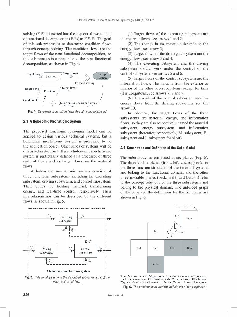
solving (F-S) is inserted into the sequential two rounds of functional decomposition (F-Fs) as F-S-Fs. The goal of this sub-process is to determine condition flows through concept solving. The condition flows are the target flows of the next functional decomposition, so this sub-process is a precursor to the next functional decomposition, as shown in Fig. 4.
Fig. 4. Determining condition flows through concept solving
2.3 A Holonomic Mechatronic System
The proposed functional reasoning model can be applied to design various technical systems, but a holonomic mechatronic system is presumed to be the application object. Other kinds of systems will be discussed in Section 4. Here, a holonomic mechatronic system is particularly defined as a processor of three sorts of flows and its target flows are the material flows.
A holonomic mechatronic system consists of three functional subsystems including the executing subsystem, driving subsystem, and control subsystem. Their duties are treating material, transforming energy, and real-time control, respectively. Their interrelationships can be described by the different flows, as shown in Fig. 5.
Fig. 5. Relationships among the described subsystems using the various kinds of flows
(1) Target flows of the executing subsystem are the material flows, see arrows 1 and 2;
(2) The change in the materials depends on the energy flows, see arrow 3;
(3) Target flows of the driving subsystem are the energy flows, see arrow 3 and 4;
(4) The executing subsystem and the driving subsystem should work under the control of the control subsystem, see arrows 5 and 6;
(5) Target flows of the control subsystem are the information flows. The input is from the exterior or interior of the other two subsystems, except for time (it is ubiquitous), see arrows 7, 8 and 9;
(6) The work of the control subsystem requires energy flows from the driving subsystem, see the arrow 10.
In addition, the target flows of the three subsystems are material, energy, and information flows, so they are also respectively named the material subsystem, energy subsystem, and information subsystem (hereafter, respectively, M_subsystem, E_subsystem and I_subsystem for short).
2.4 Description and Definition of the Cube Model
The cube model is composed of six planes (Fig. 6). The three visible planes (front, left, and top) refer to the three function-structures of the three subsystems and belong to the functional domain, and the other three invisible planes (back, right, and bottom) refer to the concept solutions of the three subsystems and belong to the physical domain. The unfolded graph of the cube and the definitions for the six planes are shown in Fig. 6.
Fig. 6. The unfolded cube and the definitions of the six planes

Strojniški vestnik - Journal of Mechanical Engineering 59(2013)5, 323-332
327A Functional Reasoning Cube Model for Conceptual Design of Mechatronic Systems
2.5 The Building Process of the Cube Model
2.5.1 The Whole Building Sequence
The building process of the cube model is a functional reasoning process, so the proposed functional reasoning model is also called the cube model. The whole building sequence of the cube applied to design a holonomic mechatronic system is shown in Fig. 7.
Fig. 7. The sketch of building the cube
The cube model can be built in seven steps according to the relationships among the three subsystems (see section 2.3) and the two reasoning sub-processes (see section 2.2).
Step 1: Building the front plane (function-structure of M_subsystem) through functional decomposition by the M_flows (the M_flows are extracted from the customer requirements).
Step 2: Building the back plane (concept solutions of the M_subsystem, M_Ss) through concept solving to provide the material functions (M_Fs) in the front plane.
Step 3: Building the left plane (function-structure of E_subsystem) through functional decomposition by the E_flows (the input E_flows are decided by the working environment, and the output E_flows are condition flows of the M_subsystem which are determined by the concept solutions in the back plane, see arrow 1).
Step 4: Building the right plane (concept solutions of E_subsystem, E_Ss) through concept solving to provide the energy functions (E_Fs) in the left plane.
Step 5: Building the top plane (function-structure of I_subsystem) through functional decomposition by the I_flows (the input and output I_flows are decided by the control strategy and they are the condition flows of the M_subsystem & E_subsystem, which are determined by the concept solutions in the back & right planes, see arrows 2 and 3).
Step 6: Building the bottom plane (concept solutions of I_subsystem, I_Ss) through concept solving to provide the information functions (I_Fs) in the top plane.
Step 7: Adjusting the left and right planes by adding the E_flows into the E_subsystem (the E_flows are the condition flows of the I_subsystem and come from the bottom plane, see arrow 4).
The whole building sequence can be simply expressed as: Front-Back-Left-Right-Top-Bottom-Left-Right.
2.5.2 The Detailed Building Process
The building processes of the front (left, top) plane and the back (right, bottom) plane are inseparable and iterative. If one concept solution can not provide the function in the front plane, function decomposition and concept solving will continue until all the functions in the front plane (left or top) are provided by the concept solutions of the back (right or bottom) plane. The detailed reasoning processes and reasoning results are shown in Fig. 8.
Fig. 8. Flow chart of detailed functional reasoning and results
Strojniški vestnik - Journal of Mechanical Engineering 59(2013)5, 323-332
328 Zou, J. – Du, Q.
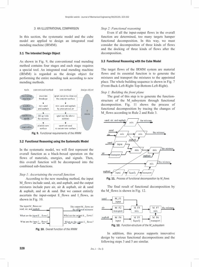
3 AN ILLUSTRATIONAL COMPARISON
In this section, the systematic model and the cube model are applied to design an integrated road mending machine (IRMM).
3.1 The Intended Design Object
As shown in Fig. 9, the conventional road mending method contains four stages and each stage requires a special tool. An integrated road mending machine (IRMM) is regarded as the design object for performing the entire mending task according to new mending methods.
Fig. 9. Functional requirements of the IRMM
3.2 Functional Reasoning using the Systematic Model
In the systematic model, we will first represent the overall function as a black-boxed operation on the flows of materials, energies, and signals. Then, this overall function will be decomposed into the combined sub-functions.
Step 1: Ascertaining the overall functionAccording to the new mending method, the input
M_flows include sand, air, and asphalt, and the output mixtures include pure air, air & asphalt, air & sand & asphalt, and air & sand. But we cannot entirely ascertain the input-output E_flows and I_flows, as shown in Fig. 10.
Fig. 10. Overall function of the IRMM
Step 2: Functional reasoningEven if all the input-output flows in the overall
function are determined, too many targets hamper functional decomposition. In this way, we must consider the decomposition of three kinds of flows and the docking of three kinds of flows after the decomposition.
3.3 Functional Reasoning with the Cube Model
The target flows of the IRMM system are material flows and its essential function is to generate the mixtures and transport the mixtures to the appointed place. The whole building sequence is shown in Fig. 7 (Front-Back-Left-Right-Top-Bottom-Left-Right).
Step 1: Building the front planeThe goal of this step is to generate the function-
structure of the M_subsystem through functional decomposition. Fig. 11 shows the process of functional decomposition by tracing the changes of M_flows according to Rule 2 and Rule 3.
Fig. 11. Process of functional decomposition by M_flows
The final result of functional decomposition by the M_flows is shown in Fig. 12.
Fig. 12. Function-structure of the M_subsystem
In addition, this process supports innovative design by various functional decompositions and the following steps 3 and 5 are similar.

Strojniški vestnik - Journal of Mechanical Engineering 59(2013)5, 323-332
329A Functional Reasoning Cube Model for Conceptual Design of Mechatronic Systems
Step 2: Building the back planeThe concept solutions of the M_subsystem (M_
S1 to M_S7) are diagramed to provide the M_Fs (Fig. 13).
In addition, this process supports innovative design by generating different concept solutions to provide a function (e.g., M_S1(a) and M_S1(b) are the different concept solutions to provide M_F1, see Fig. 13.)
Fig. 13. Concept solutions of M_subsystem
Step 3: Building the left planeMost M_Fs require energy support. The required
energy is the output E_flows of the E_subsystem. The input E_flows are decided by the working environment. As the IRMM is involved in working outdoors, neither electric power nor solar energy is the ideal input E_flows. An alternative program is the chemical energy from diesel oil. The function of the E_system is shown in Fig. 14.
The result of functional decomposition by the E_flows (function-structure of E_subsystem) is shown in Fig. 15.
Step 4: Building the right planeThe concept solutions of the E_subsystem (E_S1
to E_S6) are to provide the E_flows. The solutions are described in the shadow ellipses (Fig. 16).
Fig. 14. Function of the E_subsystem
Fig. 15. Function-structure of the E_subsystem
Fig. 16. Concept solutions of the E_subsystem
Fig. 17. Function of the I_subsystem

Strojniški vestnik - Journal of Mechanical Engineering 59(2013)5, 323-332
330 Zou, J. – Du, Q.
Fig. 18. Function-structure of the I_subsystem
Fig. 19. Concept solutions of the I_subsystem
Fig. 20. Complete functional reasoning results of the IRMM using the cube model
Step 5: Building the top planeAccording to the control strategy, asphalt
temperature, compressed air pressure, and the content of the mixture should be controlled by the I_subsystem. The input and output I_flows contain these parameters and come from the M_subsystem,
E_subsystem, or operator. The function of the I_subsystem is shown in Fig. 17.
The result of functional decomposition by I_flows (function-structure of I_subsystem) is shown in Fig. 18.
Step 6: Building the bottom planeThe concept solutions of the I_subsystem (I_S1
to I_S11) provide the I_flows. The solutions are described in the shadow ellipse (Fig. 19).
Step 7: Adjusting the left and the right planeThe required E_flow of the I_subsystem is low-
voltage DC, which can be directly provided by E_F4 (see Fig. 15).
The entire function-structure of the system is composed of three function-structures of the subsystems in the front, left, and top planes. According to the plane definitions of the cube model, the final unfolded cube model is shown in Fig. 20.
The concept solutions of the three subsystems are in the back, right, and bottom planes, respectively. The entire concept solution of the system will be generated by concept synthesizing (not covered in this paper).
3.4 Improvements to the Systematic Model
The cube model can be regarded as an improvement of the systematic model. The obvious improvements are shown in Table 1. The cube model is characterized by clear target flows, three reasoning rules, simple function structure, and a clear reasoning foundation in physical knowledge.
Table 1. Differences between the systematic model and the cube model
Improvements Systematic model Cube modelFunctional representation
Change in three sorts of flows
Change in target flows
Processes Unclear Clear process with three reasoning rules
Results a whole function-structure
Three simpler function-structures
Reasoning foundation inspiration and experience
physical knowledge
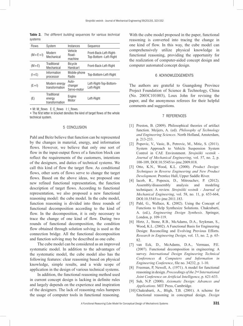
4 DISCUSSION OF THE SCOPE OF APPLICATION OF THE CUBE MODEL
The proposed cube model can be used to design other sorts of systems (except holonomic mechatronic systems). The difference lies in the building sequence of the cube, as shown in Table 2.
Strojniški vestnik - Journal of Mechanical Engineering 59(2013)5, 323-332
331A Functional Reasoning Cube Model for Conceptual Design of Mechatronic Systems
Table 2. The different building sequences for various technical systems
Flows System Instances Sequence
(M+E+I)Modern Mechanical
VehicleRoad-machine
Front-Back-Left-Right-Top-Bottom -Left-Right
(M+E)Traditional Mechanical
BicycleHandcart
Front-Back-Left-Right
(I+E)Information processor
Mobile-phoneRadio
Top-Bottom-Left-Right
(E+I)Modern energy transformation
Auto- changerServo-motor
Left-Right-Top-Bottom-Left-Right
(E)Traditional energy transformation
EngineMotor
Left-Right
• M: M_flows E: E_flows I: I_flows.• The first letter in bracket denotes the kind of target flows of the whole technical system.
5 CONCLUSION
Pahl and Beitz believe that function can be represented by the changes in material, energy, and information flows. However, we believe that only one sort of flow in the input-output flows of a function block can reflect the requirements of the customers, intentions of the designers, and duties of technical systems. We call this kind of flow the target flow. As conditional flows, other sorts of flows serve to change the target flows. Based on the above ideas, we proposed one new refined functional representation, the function description of target flows. According to functional representation, we also proposed a new functional reasoning model: the cube model. In the cube model, function reasoning is divided into three rounds of functional decomposition according to the kind of flow. In the decomposition, it is only necessary to trace the change of one kind of flow. During two rounds of functional decomposition, the condition flow obtained through solution solving is used as the connection bridge. All the functional decomposition and function solving may be described as one cube.
The cube model can be considered as an improved systematic model. In addition to the advantages of the systematic model, the cube model also has the following features: clear reasoning based on physical knowledge, simple results, and a wide scope of application in the design of various technical systems.
In addition, the functional reasoning method used in current concept design is lacking in definite rules and largely depends on the experience and inspiration of the designers. The lack of reasoning rules hampers the usage of computer tools in functional reasoning.
With the cube model proposed in the paper, functional reasoning is converted into tracing the change in one kind of flow. In this way, the cube model can comprehensively utilize physical knowledge in functional reasoning, providing the opportunity for the realization of computer-aided concept design and computer automated concept design.
6 ACKNOWLEDGEMENTS
The authors are grateful to Guangdong Province Project Foundation of Science & Technology, China (No. 2003C101003), Loux John for revising the paper, and the anonymous referees for their helpful comments and suggestions.
7 REFERENCES
[1] Preston, B. (2009). Philosophical theories of artifact function. Meijers, A. (ed). Philosophy of Technology and Engineering Sciences. North Holland, Amsterdam, p. 213-233.
[2] Popovic, V., Vasic, B., Petrovic, M., Mitic, S. (2011). System Approach to Vehicle Suspension System Control in CAE Environment. Strojniški vestnik - Journal of Mechanical Engineering, vol. 57, no. 2, p. 100-109, DOI:10.5545/sv-jme.2009.018.
[3] Otto, K.N., Wood, K.L. (2000). Product Design: Techniques in Reverse Engineering and New Product Development. Prentice Hall, Upper Saddle River.
[4] Iacob, R., Popescu, D., Mitrouchev, P. (2012). Assembly/disassembly analysis and modeling techniques: A review. Strojniški vestnik - Journal of Mechanical Engineering, vol. 58, no. 11, p. 653-664, DOI:10.5545/sv-jme.2011.183.
[5] Pahl, G., Wallace, K. (2002). Using the Concept of Functions to Help Synthesize Solutions. Chakrabarti, A. (ed.), Engineering Design Synthesis. Springer, London, p. 109-119.
[6] Hirtz, J., Stone, R.B., McAdams, D.A., Szykman, S., Wood, K.L. (2002). A Functional Basis for Engineering Design: Reconciling and Evolving Previous Efforts. Research in Engineering Design, vol. 13, no. 2, p. 65-82.
[7] van Eck, D., McAdams, D.A., Vermaas, P.E. (2007). Functional decomposition in engineering: A survey. International Design Engineering Technical Conferences & Computers and Information in Engineering Conference, file no. 34232, p. 1-10.
[8] Freeman, P, Newell, A. (1971). A model for functional reasoning in design. Proceedings of the 2nd International Joint Conference on Artificial Intelligence, p. 621-633.
[9] Suh, N.P. (2000). Axiomatic Design: Advances and Applications. MIT Press, Cambridge.
[10] Chakrabarti, A., Bligh, T.B. (2001). A scheme for functional reasoning in conceptual design. Design

Strojniški vestnik - Journal of Mechanical Engineering 59(2013)5, 323-332
332 Zou, J. – Du, Q.
Studies, vol. 22, no. 6, p. 493-517, DOI:10.1016/S0142-694X(01)00008-4.
[11] Liu, Y.C., Bligh, T., Chakrabarti, A. (2003). Towards an 'ideal' approach for concept generation. Design Studies, vol. 24, no. 4, p. 341-355, DOI:10.1016/S0142-694X(03)00003-6.
[12] Sturges, R.H., Shaughnessy, K.O., Kilani, M.I. (1996). Computational model for conceptual design based on extended function logic. Artificial Intelligence for Engineering Design, Analysis, and Manufacturing, vol. 10, no. 4, p. 255-274, DOI:10.1017/S089006040000161X.
[13] Gero, J.S., Kannengiesser, U. (2004). The situated function-behaviour-structure framework. Design Studies, vol. 25, no. 4 p. 373-391, DOI:10.1016/j.destud.2003.10.010.
[14] Umeda, Y., Ishii, M., Youshioka, M., Shimomura, Y., Tomiyama, T. (1996). Supporting conceptual design based on the function-behavior-state modeler. Artificial Intelligence for Engineering Design, Analysis, and Manufacturing, vol. 10, no. 4, p. 275-288, DOI:10.1017/S0890060400001621.
[15] Roy, U., Pramanik, N., Sudarsan, R., Sriram, R.D, Lyons, K.W. (2001). Function-to-form mapping: model representation and application in design synthesis. Computer-Aided Design, vol. 33, no. 10, p. 699-719, DOI:10.1016/S0010-4485(00)00100-7.
[16] Yong, X., Zou, H.J. (2007). A function-oriented theoretical framework for mechatronic system design. Strojniški vestnik - Journal of Mechanical Engineering, vol. 53, no. 4, p. 241-252.
[17] Garbacz, P. (2007) A formal model of functional decomposition. ASME 2006 International Design Engineering Technical Conferences & Computers and Information in Engineering Conference, file no. 99097, p. 1-10.
[18] Pahl, G., Beitz, W. (1996). Engineering Design: a Systematic Approach. SpringerVerlag, London.
[19] Chittaro, L., Kumar, A.N. (1998). Reasoning about function and its applications to engineering. Artificial Intelligence in Engineering, vol. 12, no. 4, p. 331-336, DOI:10.1016/S0954-1810(97)10008-5.
[20] Deng, Y.M. (2002). Function and behavior representation in conceptual mechanical design. Artificial Intelligence for Engineering Design, Analysis, and Manufacturing, vol. 16, no. 5, p. 343-362, DOI:10.1017/S0890060402165024.
[21] Far, B.H., Elamy, A.H. (2005). Functional reasoning theories: problems and perspectives. Artificial Intelligence for Engineering Design, Analysis, and Manufacturing, vol. 19, no. 2, p. 75-88, DOI:10.1017/S0890060405050080.
[22] Zadnik, Z., Karakasic, M., Kljajin, M., Duhovnik, J. (2009). Function and functionality in the conceptual design process. Strojniški vestnik - Journal of Mechanical Engineering, vol. 55, no. 7-8, p. 455-471.
[23] Ullman, DG. (2002). Toward the ideal mechanical engineering design support system. Research in Engineering Design, vol. 13, no. 2, p. 55-64.
[24] Hubka, V., Eder, W.E. (1988). Theory of Technical Systems: A Total Concept Theory for Engineering Design. Springer Verlag, Berlin, DOI:10.1007/978-3-642-52121-8.