a grid-connected pv system utilizing transformer-less ...lation technique for the current source...
TRANSCRIPT
Volume No: 2 (2015), Issue No: 6 (June) June 2015 www.ijmetmr.com Page 532
ISSN No: 2348-4845International Journal & Magazine of Engineering,
Technology, Management and ResearchA Peer Reviewed Open Access International Journal
A renewable energy system convert the energy found in sunlight, falling-water, wind, sea-waves, geothermal heat, or biomass into a form, which we can use in the form of heat or electricity. The majority of the renew-able energy comes either directly or indirectly from sun and wind and can never be fatigued, and therefore they are called renewable. However, the majority of the world’s energy sources came from conventional sources- fossil fuels such as coal, natural gases and oil. These fuels are often term non-renewable energy sources. Though, the available amount of these fuels are extremely large, but due to decrease in level of fos-sil fuel and oil level day by day after a few years it will end. Hence renewable energy source demand increas-es as it is environmental friendly and pollution free which reduces the greenhouse effect. The Convention-al sources of energy are rapidly depleting. Moreover the cost of energy is rising and therefore photovoltaic (PV) system is a promising alternative. They are abun-dant, pollution free, distributed throughout the earth and recyclable. The hindrance factor is its high installa-tion cost and low conversion efficiency. Therefore our aim is to increase the efficiency and power output of the system. It is also required that constant voltage is supplied to the load irrespective of the variation in so-lar irradiance and temperature.
Photovoltaic Arrangements:
PV cells are made of semiconductor materials, such as silicon. For solar cells, a thin semiconductor wafer is specially treated to form an electric field, positive on one side and negative on the other.
Abstract:
Inverter is one of power conversion device that widely used in the world to convert DC input voltage to AC output voltage. The output voltage waveforms of ideal inverters should be sinusoidal. This paper presents a single-phase, single-stage current source inverter (CSI) based photovoltaic system (PV) for grid connection. A double-tuned parallel resonant circuit is designed to at-tenuate the second- and fourth- order harmonics at the inverter dc side. It helps to improve the power quality and system efficiency. A modified carrier based modu-lation technique for the current source inverter is stud-ied to magnetize the dc-link inductor and to control the switching pattern for the single phase grid-connected CSI. The operation of Single Phase Transformer-less grid connected PV system is verified by the simulation using MATLAB/Simulink software. The results are ana-lyzed and presented.
Keywords:
PV System, Inverter, PIC Controller, Matlab/simulink
Introduction:
Renewable energy sources also called non-convention-al type of energy are the sources which are continu-ously replenished by natural processes. Such as, solar energy, bio-energy - bio-fuels grown sustainably, wind energy and hydropower etc., are some of the examples of renewable energy sources.
B. RameshM.Tech (Electrical Power Systems),
Department of EEE,Balaji Institute of Technology and Science,
Laknepally, Narsampet, Warangal, Telangana.
G. MadhuriAssistant Professor, Department of EEE,
Balaji Institute of Technology and Science, Laknepally, Narsampet, Warangal, Telangana.
A Grid-Connected PV System Utilizing Transformer-Less Single-Stage Conversion for Tracking the Maximum
Power Point
Volume No: 2 (2015), Issue No: 6 (June) June 2015 www.ijmetmr.com Page 533
ISSN No: 2348-4845International Journal & Magazine of Engineering,
Technology, Management and ResearchA Peer Reviewed Open Access International Journal
Proposed System:
The system utilizes transformer-less single-stage con-version for tracking the maximum power point and interfacing the photovoltaic array to the grid. The maximum power point is maintained with a fuzzy logic controller. A proportionalresonant controller is used to control the current injected into the grid.
To improve the power quality and system efficiency, a double-tuned parallel resonant circuit is proposed to attenuate the second- and fourth- order harmonics at the inverter dc side.
The dc input current is continuous which is important for a PV application; system reliability is increased by replacing the shunt input electrolytic capacitor with a series input inductor; the VSI voltage bucking capabil-ity allows a low-voltage PV array to be grid interface without the need of a transformer or an additional boost stage.
Reduce the electrical stress on the Power switches, and reduce the power losses due to a high switching frequency.
Grid-Tied Inverter:
A grid-tie inverter (GTI) is a special type of inverter that converts direct current(DC) electricity into alternating current (AC) electricity and feeds it into an existing elec-trical grid. GTIs are often used to convert direct current produced by many renewable energy sources, such as solar panels or small wind turbines, into the alternat-ing current used to power homes and businesses. The technical name for a grid-tie inverter is “grid-interactive inverter”. They may also be called synchronous invert-ers. Grid-interactive inverters typically cannot be used in standalone applications where utility power is not available.
EXISTING SYSTEM:
A two-stage grid-connected PV system utilizes two conversion stages: a dc/dc converter for boosting and conditioning the PV output voltage and tracking the MPP, and a dc/ac inverter for interfacing the PV system to the grid. In such a topology, a high-voltage PV ar-ray is not essential, because of the dc voltage boost-ing stage. However, this two-stage technique suffers from reduced efficiency, higher cost, and larger size. From the aforementioned drawbacks of existing grid connected PV systems, it is apparent that the efficiency and footprint of the twostage grid-connected system are not attractive. Therefore, single-stage inverters have gained attention, Especially in low voltage appli-cations.
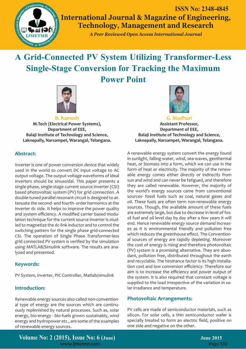
When light energy strikes the solar cell, electrons are knocked loose from the atoms in the semiconductor ma-terial. If electrical conductors are attached to the positive and negative sides, forming an electrical circuit, the electrons can be captured in theform of an electric current - that is, electricity. This electricity can then be used to power a load. A PV cell can either be circular or square in construction
Basic Structure of PV Cell

Volume No: 2 (2015), Issue No: 6 (June) June 2015 www.ijmetmr.com Page 534
ISSN No: 2348-4845International Journal & Magazine of Engineering,
Technology, Management and ResearchA Peer Reviewed Open Access International Journal
Double-Tuned Resonant Filter:
In a single-phase CSI, the pulsating instantaneous power oftwice the system frequency generates even harmon-ics in the dc-link current. These harmonics reflect onto the ac side as low order odd harmonics in the current and voltage. Undesirably, these even harmonics affect MPPT in PV system applications and reduce the PV lifetime. In order to mitigate the impact of these dc-side harmonics on the ac side and on the PV, the dc link inductance must be large enough to suppress the dc-link current ripple produced by these harmonics. Practically, large dc-link in-ductance is not acceptable, because of its cost, size, weight, and the fact that it slows MPPT transient response.
To reduce the necessary dc-link inductance, a parallel resonant circuit tuned to the second-order harmonic is em-ployed in series with the dc-link inductor. The filter is capable of smoothing the dc-link current by using relatively small inductances. Even though the impact of the second-order harmonic is significant in the dc-link current, the fourth-order harmonic can also affect the dc-link current, especially when the CSI operates at high modulation indi-ces. Therefore, in an attempt to improve the parallel resonant circuit, this paper proposes a double-tuned parallel resonant circuit tuned at the second- and fourth-order harmonics, as shown in Fig.
Proposed double-tuned resonant filter.
RESULTS:
Under Normal Weather Condition:
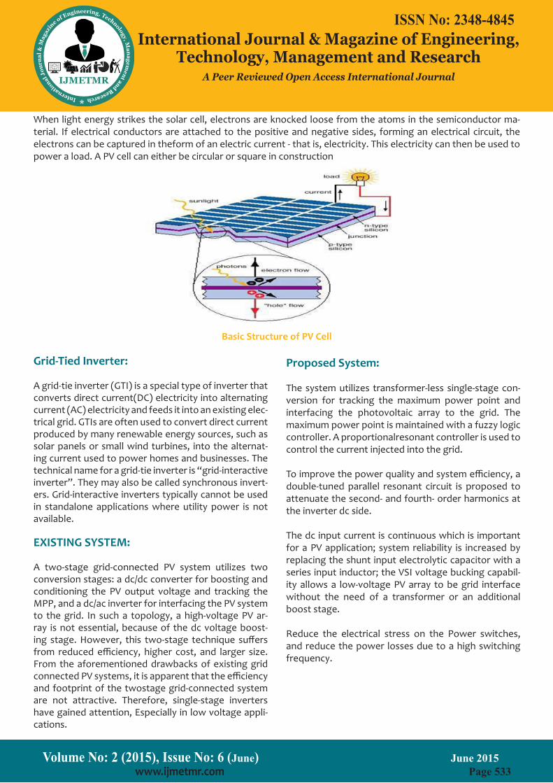
The results of the proposed system under normal weather conditions are shown in Fig below. The PV maximum power is extracted in a relatively short time with small oscillation in steady state, as shown in Fig.(a). Moreover, MPPT successfully locks the dc current to the optimum value, as shown in Fig. (b).
Circuit Diagram:
Volume No: 2 (2015), Issue No: 6 (June) June 2015 www.ijmetmr.com Page 535
ISSN No: 2348-4845International Journal & Magazine of Engineering,
Technology, Management and ResearchA Peer Reviewed Open Access International Journal
Fig.: (a) PV output power
(b) PV output current
Volume No: 2 (2015), Issue No: 6 (June) June 2015 www.ijmetmr.com Page 536
ISSN No: 2348-4845International Journal & Magazine of Engineering,
Technology, Management and ResearchA Peer Reviewed Open Access International Journal
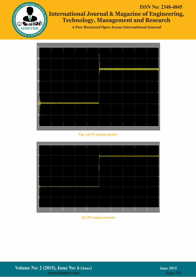
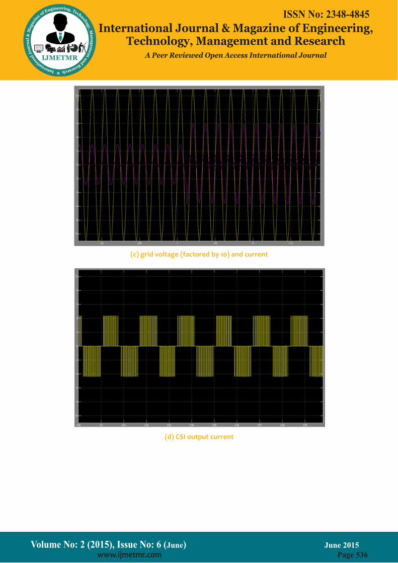
(c) grid voltage (factored by 10) and current
(d) CSI output current
Volume No: 2 (2015), Issue No: 6 (June) June 2015 www.ijmetmr.com Page 537
ISSN No: 2348-4845International Journal & Magazine of Engineering,
Technology, Management and ResearchA Peer Reviewed Open Access International Journal
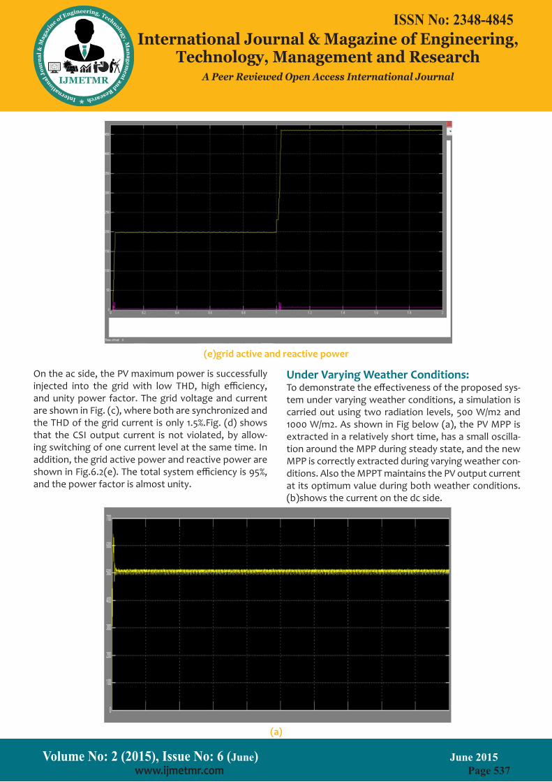
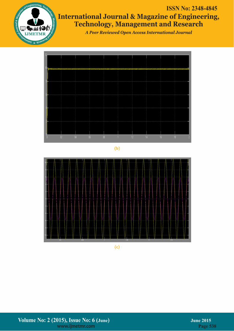
Under Varying Weather Conditions:To demonstrate the effectiveness of the proposed sys-tem under varying weather conditions, a simulation is carried out using two radiation levels, 500 W/m2 and 1000 W/m2. As shown in Fig below (a), the PV MPP is extracted in a relatively short time, has a small oscilla-tion around the MPP during steady state, and the new MPP is correctly extracted during varying weather con-ditions. Also the MPPT maintains the PV output current at its optimum value during both weather conditions. (b)shows the current on the dc side.
On the ac side, the PV maximum power is successfully injected into the grid with low THD, high efficiency, and unity power factor. The grid voltage and current are shown in Fig. (c), where both are synchronized and the THD of the grid current is only 1.5%.Fig. (d) shows that the CSI output current is not violated, by allow-ing switching of one current level at the same time. In addition, the grid active power and reactive power are shown in Fig.6.2(e). The total system efficiency is 95%, and the power factor is almost unity.
(e)grid active and reactive power
(a)
Volume No: 2 (2015), Issue No: 6 (June) June 2015 www.ijmetmr.com Page 538
ISSN No: 2348-4845International Journal & Magazine of Engineering,
Technology, Management and ResearchA Peer Reviewed Open Access International Journal
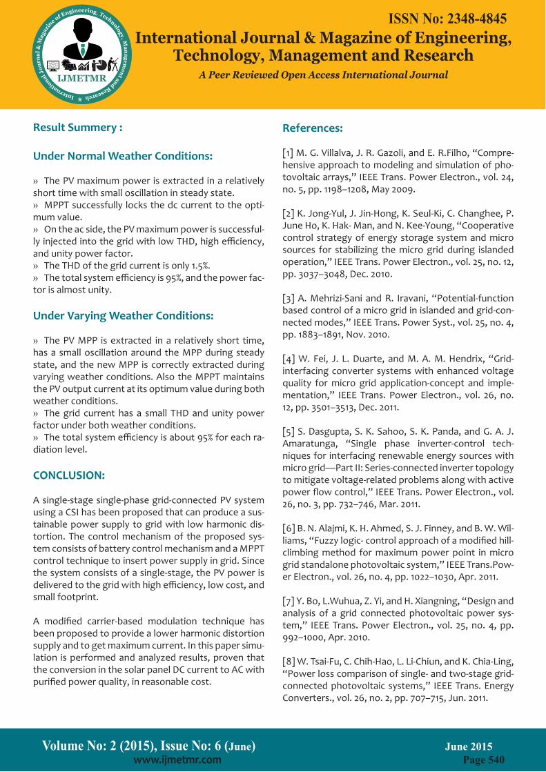
(b)
(c)

Volume No: 2 (2015), Issue No: 6 (June) June 2015 www.ijmetmr.com Page 539
ISSN No: 2348-4845International Journal & Magazine of Engineering,
Technology, Management and ResearchA Peer Reviewed Open Access International Journal
(d)
(e)
Fig. Simulation results of the proposed system under two radiation levels: 500 and 1000 W/m2 . (a) PV output power, (b) PV output current, (c) grid voltage(factored by 10) and current, (d) CSI output current, and (e) grid
active and reactive power.
Volume No: 2 (2015), Issue No: 6 (June) June 2015 www.ijmetmr.com Page 540
ISSN No: 2348-4845International Journal & Magazine of Engineering,
Technology, Management and ResearchA Peer Reviewed Open Access International Journal
References:
[1] M. G. Villalva, J. R. Gazoli, and E. R.Filho, “Compre-hensive approach to modeling and simulation of pho-tovoltaic arrays,” IEEE Trans. Power Electron., vol. 24, no. 5, pp. 1198–1208, May 2009.
[2] K. Jong-Yul, J. Jin-Hong, K. Seul-Ki, C. Changhee, P. June Ho, K. Hak- Man, and N. Kee-Young, “Cooperative control strategy of energy storage system and micro sources for stabilizing the micro grid during islanded operation,” IEEE Trans. Power Electron., vol. 25, no. 12, pp. 3037–3048, Dec. 2010.
[3] A. Mehrizi-Sani and R. Iravani, “Potential-function based control of a micro grid in islanded and grid-con-nected modes,” IEEE Trans. Power Syst., vol. 25, no. 4, pp. 1883–1891, Nov. 2010.
[4] W. Fei, J. L. Duarte, and M. A. M. Hendrix, “Grid-interfacing converter systems with enhanced voltage quality for micro grid application-concept and imple-mentation,” IEEE Trans. Power Electron., vol. 26, no. 12, pp. 3501–3513, Dec. 2011.
[5] S. Dasgupta, S. K. Sahoo, S. K. Panda, and G. A. J. Amaratunga, “Single phase inverter-control tech-niques for interfacing renewable energy sources with micro grid—Part II: Series-connected inverter topology to mitigate voltage-related problems along with active power flow control,” IEEE Trans. Power Electron., vol. 26, no. 3, pp. 732–746, Mar. 2011.
[6] B. N. Alajmi, K. H. Ahmed, S. J. Finney, and B. W. Wil-liams, “Fuzzy logic- control approach of a modified hill-climbing method for maximum power point in micro grid standalone photovoltaic system,” IEEE Trans.Pow-er Electron., vol. 26, no. 4, pp. 1022–1030, Apr. 2011.
[7] Y. Bo, L.Wuhua, Z. Yi, and H. Xiangning, “Design and analysis of a grid connected photovoltaic power sys-tem,” IEEE Trans. Power Electron., vol. 25, no. 4, pp. 992–1000, Apr. 2010.
[8] W. Tsai-Fu, C. Chih-Hao, L. Li-Chiun, and K. Chia-Ling, “Power loss comparison of single- and two-stage grid-connected photovoltaic systems,” IEEE Trans. Energy Converters., vol. 26, no. 2, pp. 707–715, Jun. 2011.
Result Summery :
Under Normal Weather Conditions:
The PV maximum power is extracted in a relatively »short time with small oscillation in steady state.
MPPT successfully locks the dc current to the opti- »mum value.
On the ac side, the PV maximum power is successful- »ly injected into the grid with low THD, high efficiency, and unity power factor.
The THD of the grid current is only 1.5%. »The total system efficiency is 95%, and the power fac- »
tor is almost unity.
Under Varying Weather Conditions:
The PV MPP is extracted in a relatively short time, »has a small oscillation around the MPP during steady state, and the new MPP is correctly extracted during varying weather conditions. Also the MPPT maintains the PV output current at its optimum value during both weather conditions.
The grid current has a small THD and unity power »factor under both weather conditions.
The total system efficiency is about 95% for each ra- »diation level.
CONCLUSION:
A single-stage single-phase grid-connected PV system using a CSI has been proposed that can produce a sus-tainable power supply to grid with low harmonic dis-tortion. The control mechanism of the proposed sys-tem consists of battery control mechanism and a MPPT control technique to insert power supply in grid. Since the system consists of a single-stage, the PV power is delivered to the grid with high efficiency, low cost, and small footprint.
A modified carrier-based modulation technique has been proposed to provide a lower harmonic distortion supply and to get maximum current. In this paper simu-lation is performed and analyzed results, proven that the conversion in the solar panel DC current to AC with purified power quality, in reasonable cost.
Volume No: 2 (2015), Issue No: 6 (June) June 2015 www.ijmetmr.com Page 541
ISSN No: 2348-4845International Journal & Magazine of Engineering,
Technology, Management and ResearchA Peer Reviewed Open Access International Journal
[11] E. Villanueva, P. Correa, J. Rodriguez, and M. Pacas, “Control of a single phase cascaded H-bridge multilev-el inverter for grid-connected photovoltaic systems,” IEEE Trans. Ind. Electron., vol. 56, no. 11, pp. 4399– 4406, Nov. 2009.
[12] C. Cecati, F. Ciancetta, and P. Siano, “A multilevel inverter for photovoltaic systems with
[9] S. B. Kjaer, J. K. Pedersen, and F. Blaabjerg, “A re-view of single-phase grid-connected inverters for pho-tovoltaic modules,” IEEE Trans. Ind.Appl., vol. 41, no. 5, pp. 1292–1306, Sep.–Oct. 2005.
[10] G. Petrone, G. Spagnuolo, and M. Vitelli, “A mul-tivariable perturband- observe maximum power point tracking technique applied to a single-stage photovol-taic inverter,” IEEE Trans. Ind. Electron., vol. 58, no. 1, pp. 76–84, Jan. 2011.