a liquid hydrogen target for the muse experiment at psi
TRANSCRIPT

Nuclear Inst. and Methods in Physics Research, A 949 (2020) 162874
Contents lists available at ScienceDirect
Nuclear Inst. and Methods in Physics Research, A
journal homepage: www.elsevier.com/locate/nima
A liquid hydrogen target for the MUSE experiment at PSIP. Roy a, S. Corsetti a, M. Dimond a, M. Kim a, L. Le Pottier a, W. Lorenzon a,∗, R. Raymond a,H. Reid a, N. Steinberg a, N. Wuerfel a, K. Deiters b, W.J. Briscoe c, A. Golossanov c,T. Rostomyan d,b
a Randall Laboratory of Physics, University of Michigan, Ann Arbor, MI 48109-1040, USAb Paul Scherrer Institut, CH-5232 Villigen, PSI, Switzerlandc Department of Physics, The George Washington University, Washington, D.C. 20052, USAd Rutgers, The State University of New Jersey, Piscataway, NJ 08855, USA
A R T I C L E I N F O
Keywords:Liquid hydrogen targetMuon beamMUSEElastic scattering
A B S T R A C T
A 280 ml liquid hydrogen target has been constructed and tested for the MUSE experiment at PSI to investigatethe proton charge radius via simultaneous measurement of elastic muon–proton and elastic electron–protonscattering. To control systematic uncertainties at a sub-percent level, strong constraints were put on the amountof material surrounding the target and on its temperature stability. The target system was successfully operatedduring a commissioning run at PSI at the end of 2018. The target temperature was stable at the 0.01 K level.This suggests a density stability at the 0.02% level, which is about a factor of ten better than required.
1. Introduction
Until recently, the proton charge radius had been well establishedat 𝑟𝑝 = 0.8768(69) fm [1] from electronic-hydrogen spectroscopy andelectron–proton scattering measurements. However in 2010, a novelexperiment using muonic-hydrogen spectroscopy [2] determined theproton charge radius to be 𝑟𝑝 = 0.84184(67) fm. This roughly five-standard-deviation difference has become known as the proton radiuspuzzle [3].
The MUon Scattering Experiment (MUSE) [4], located in the PiM1area of the Paul Scherrer Institute (PSI) in Switzerland, is part of asuite of experiments that aim to resolve the proton radius puzzle. MUSEattempts to determine the proton charge radius through simultaneousmeasurements of muon–proton and electron–proton elastic scatteringcross sections with high precision. The experimental kinematics coverthree beam momenta of about 115, 153, and 210 MeV/𝑐 and scatteringangles in the range of 20◦–100◦, corresponding to 𝑄2 of approxi-mately 0.002 (GeV/c)2–0.08 (GeV/c)2, the range of the form factor withgreatest sensitivity to the radius [4].
At the heart of the experiment is a liquid hydrogen (LH2) targetthat needs to provide stable density and sufficient cooling power tominimize uncertainty in target length in order to allow cross sectionmeasurements at the sub-percent level. Since hydrogen is highly ex-plosive, special precautions had to be taken to ensure safe handling.Driven by the science needs for MUSE, the experimental requirements
∗ Corresponding author.E-mail address: [email protected] (W. Lorenzon).
1 Both, a vertical and horizontal cylindrical cell geometry were initially considered. But Monte Carlo simulations revealed that, given MUSE’s large acceptance,a vertical cylindrical cell geometry was a favorable choice over a horizontal cylindrical cell geometry.
for the target system [4] include not only a LH2 cell, but also an emptycell for studying background generated from the target walls and a setof thin, solid targets for precision vertex reconstruction and detectoralignment. To facilitate rapid switching between the LH2 and emptytarget cells, and to accommodate the MUSE spectrometer geometry, thetarget system has to be movable in the vertical direction. Furthermore,large thin vacuum windows on either side of the beamline are neededto cover the very large solid angle subtended by the detectors whileintroducing minimal amounts of multiple scattering.
A LH2 target system that met all experimental and safety require-ments was designed and fabricated in close collaboration with CreareInc. [5], and then installed and thoroughly tested at PSI. This paperdescribes the major components of the target apparatus and presentsdata demonstrating the successful operation of the LH2 target.
2. Target system
The MUSE target system, shown in Fig. 1, consists of a target ladderwith a variety of targets, a cryocooler and condenser assembly thatliquefies the hydrogen gas, a vacuum chamber that houses the targetladder, a lifting mechanism that allows fast switching of the targetcells, a gas handling system, and a slow control system that regulatestemperature and the hydrogen gas flow in and out of the target cell.1
https://doi.org/10.1016/j.nima.2019.162874Received 5 July 2019; Received in revised form 22 September 2019; Accepted 26 September 2019Available online 30 September 20190168-9002/Published by Elsevier B.V.

P. Roy, S. Corsetti, M. Dimond et al. Nuclear Inst. and Methods in Physics Research, A 949 (2020) 162874
Fig. 1. Left Panel: Schematic view of the trapezoidal vacuum chamber and the lifting assembly mounted on a support stand. The vacuum chamber is 66 cm high. Right Panel:Close-up view of the lifting assembly components that facilitate the vertical motion of the target ladder. The bellows outer diameter is 19 cm.
2.1. Target ladder
The target ladder, shown in Fig. 2, can be moved in and out of theparticle beam in the vertical direction. The main target, shown in Fig. 3,is a 280 ml LH2 cell assembled from a 6 cm inner diameter Kapton®cylinder and copper end caps that provide strength and stability to theKapton® wall. It is operated at a temperature of 20.65 K and a pressureof 1.1 bar.
The cell wall is made with four wraps of a single sheet of 25 μm-thick Kapton® foil which is 130 mm wide and 758 mm long. The fourwraps are glued together using Stycast 1266 epoxy. The thickness ofthe epoxy layers is controlled to achieve a total cell wall thicknessof about 120 μm. To form a strong glue joint between the end capsand the cylinder, each copper end cap reaches 1 cm into the Kapton®cylinder. This leads to a cell with a 11 cm high, thin Kapton® wall tominimize background from scattering from the copper end caps intothe detectors. The cells are further reinforced by first gluing two 9 mm-wide Kapton® strips, followed by two 5 mm-wide Kapton® strips overthe glue joints between the cylinder and the end caps, as shown inFig. 3. Burst tests performed at room temperature have consistentlyshown that the cells can withstand pressures of over 3.8 bar. This ishigher than the PSI safety group’s required safety factor of three overthe normal operational pressure of about 1.1 bar.
The target cell has two level sensors (with one serving as a backup)mounted on the inner surface of the top end cap. Each sensor is a 100 ΩAllen Bradley carbon resistor driven at 20 mA. One Lakeshore Cernox®thin film resistance cryogenic temperature sensor and one (50 Ω, 50 W)cartridge heater are mounted on the outer face of the bottom end cap(see Fig. 3). The temperature sensor, the level sensors, and the heaterare all monitored and controlled by the slow control system describedin Section 2.6. Below the LH2 target cell is an empty target cell which isidentical to the LH2 cell. It is used to subtract background originatingfrom the Kapton® walls, and to a lesser extent from the copper endcaps of the LH2 cell. A small orifice on the top end cap of the emptycell connects its inner space to the vacuum that surrounds the targetladder.
Two 6 cm-wide, 2.9 cm-high and 1 mm-thick solid targets, sepa-rated by a 2 mm gap, are attached below the empty cell, with the
Fig. 2. CAD drawing of the target ladder connected to the condenser showing thetarget positions (LH2 cell, empty cell, CH2 target, C target, empty space) as wellas the location of the beam focusing detector and the optical ‘‘bull’s-eye’’ target. Atotal vertical displacement of 34 cm is required to attain all positions. Note that thesuperinsulation wrap and the copper braids are omitted for clarity.
polyethylene (CH2) target mounted above the carbon (C) target. Theirflat, two-dimensional shapes provide a simple geometry to precisely testthe quality of the reconstructed interaction vertices, and their thicknessis chosen to match the expected vertex reconstruction resolution, which
2

P. Roy, S. Corsetti, M. Dimond et al. Nuclear Inst. and Methods in Physics Research, A 949 (2020) 162874
is at best 1–2 mm.2 A beam focusing detector, installed just below thecarbon target, is used to check beam focusing in the target region. Thebeam focusing detector, shown in Fig. 4, consists of three scintillatorsmounted in a horizontal line, with 1 cm separation. The scintillators aremade of 2×2×2 mm3 plastic, and are connected by light guides to siliconphotomultipliers (SiPMs) [6]. The beam focusing detector can also beused to map out the vertical beam profile by moving the assembly inthe vertical direction.
Just below the beam focusing detector is an optical target. Thistarget is viewed by a camera to determine the horizontal position ofthe target ladder inside the vacuum chamber to better than 0.1 mm,using pattern recognition. The lowest target position, noted as ‘‘emptyspace’’ position in Fig. 2 is used to study background events arisingfrom interactions with materials in the experimental setup aside fromthe target cell.
The target ladder is connected to the condenser through the hydro-gen fill-and-return tube which contains VCR® metal gasket face sealfittings for ease of changing ladders. Two thin tubes, made of precisionstainless steel, support the empty cell, the carbon target and the beamfocusing detector. They are positioned so as to minimize interferencewith scattered particles. The support tubes also maintain alignmentbetween the LH2 cell and the empty cell to within a few hundredmicrons. Cooling of the empty cell is achieved through copper braidsconnected to the LH2 cell.
The heat load on the target from the particle beam, which hasa nominal spot size of approximately 1 cm (sigma) and an intensityof about 0.5 pA, is less than 10 μW [4]. The approximately 1.4 Wradiation heat load from the vacuum chamber on the target cells isreduced to about 130 mW by wrapping 10 layers of aluminized Mylar®superinsulation around the entire target ladder above the solid targets,which includes the two target cells, the precision stainless steel supporttubes, and the condenser. Heat load on the target due to conduction isnegligible.
2.2. Cryocooler and condenser assembly
The CH110-LT single-stage cryocooler from Sumitomo Heavy In-dustries Ltd was selected for refrigeration.3 It has a cooling power of25 W at 20 K which is sufficient to cool down and fill the target cell inapproximately 2.6 h.
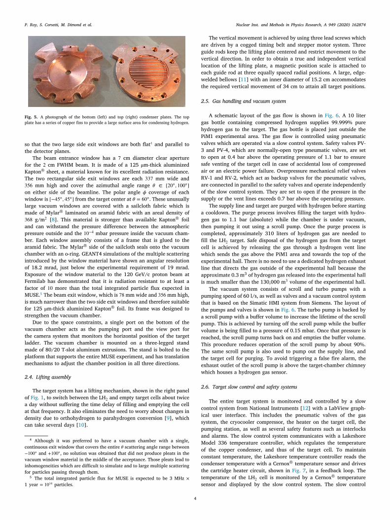
The condenser, shown in Fig. 5, is made of two copper platessoldered together to enclose a cavity with an internal surface area of346 cm2 for collecting and condensing hydrogen gas. The top plate hasa series of copper fins to provide the large surface area for condensinghydrogen, while the bottom plate contains a shallow, cone-shaped floorthat guides the liquefied hydrogen to the fill tube in the center ofthe bottom plate. The fill tube is made of heavy-walled copper with a8 mm inner and a 20 mm outer diameter and forms the sole connectionbetween the condenser and the target ladder. Boiled-off hydrogen fromthe target cell returns to the condenser cavity through the same tube.
The condenser is bolted to the cryocooler cold head. Apiezon N,a very low vapor pressure vacuum grease, is used to establish goodthermal contact between the cold head and the condenser. In order tomaintain constant temperature in the target cell, the condenser has twoidentical 25 Ω, 100 W heater circuits and two Cernox® temperature sen-sors which are controlled by the slow control system (see Section 2.6).One heater circuit and one temperature sensor are for regular operationwhile the others serve as backups.
2 Vertex reconstruction resolution for large angle scattering events is about1–2 mm in y (vertical) and z (along beam), but 1–2 cm in x (horizontal), whilefor small angle scattering events, it is about 1–2 mm in transverse directionand 1–2 cm in z (rms).
3 Sumitomo was chosen over Cryomech partly because similar cryocoolersare commonly used at PSI and because Sumitomo has a service center inDarmstadt, Germany.
Fig. 3. A photograph of the LH2 cell (top) and empty cell (bottom). The cell isreinforced with two wide and two narrow Kapton® strips glued to the end caps. Alsoshown is the cartridge heater, containing one 50 Ω, 50 W resistor, and one Cernox®temperature sensor (partially hidden) attached to the end cap of the LH2 cell.
Fig. 4. A schematic view of the beam focusing detector. Beam positions are measuredwith three small scintillators that are connected by light guides to SiPMs.
A feedthrough collar with three ports is connected to the chambertop. Two of the ports hold electrical feedthroughs for target temper-ature control and the beam focusing detector, and one port providesthe fluid feedthrough. The electrical feedthrough for the beam focusingdetector provides both low voltage to the SiPMs and signal readout foreach of the three SiPMs. The fluid feedthrough contains the stainlesssteel tubing for hydrogen gas inlet and outlet.
2.3. Vacuum chamber
The vacuum chamber, shown in the left panel of Fig. 1, is 66 cmhigh. Due to the considerable space constraints imposed on the targetsystem by the detectors, its horizontal dimensions are limited to a cir-cular area with a diameter of 48 cm. The chamber is made of stainlesssteel plates with a thickness of 9.5 mm. Based on structural stressanalysis using the ‘‘static structural’’ portion of the ANSYS simulationsoftware, this wall thickness provides at least a factor of two safetyfactor from the yield point [7]. The chamber has a trapezoidal shape
3
P. Roy, S. Corsetti, M. Dimond et al. Nuclear Inst. and Methods in Physics Research, A 949 (2020) 162874
Fig. 5. A photograph of the bottom (left) and top (right) condenser plates. The topplate has a series of copper fins to provide a large surface area for condensing hydrogen.
so that the two large side exit windows are both flat4 and parallel tothe detector planes.
The beam entrance window has a 7 cm diameter clear aperturefor the 2 cm FWHM beam. It is made of a 125 μm-thick aluminizedKapton® sheet, a material known for its excellent radiation resistance.The two rectangular side exit windows are each 337 mm wide and356 mm high and cover the azimuthal angle range 𝜃 ∈ [20◦, 100◦]on either side of the beamline. The polar angle 𝜙 coverage of eachwindow is [−45◦, 45◦] from the target center at 𝜃 = 60◦. These unusuallylarge vacuum windows are covered with a sailcloth fabric which ismade of Mylar® laminated on aramid fabric with an areal density of368 g/m2 [8]. This material is stronger than available Kapton® foiland can withstand the pressure difference between the atmosphericpressure outside and the 10−4 mbar pressure inside the vacuum cham-ber. Each window assembly consists of a frame that is glued to thearamid fabric. The Mylar® side of the sailcloth seals onto the vacuumchamber with an o-ring. GEANT4 simulations of the multiple scatteringintroduced by the window material have shown an angular resolutionof 18.2 mrad, just below the experimental requirement of 19 mrad.Exposure of the window material to the 120 GeV/c proton beam atFermilab has demonstrated that it is radiation resistant to at least afactor of 10 more than the total integrated particle flux expected inMUSE.5 The beam exit window, which is 78 mm wide and 356 mm high,is much narrower than the two side exit windows and therefore suitablefor 125 μm-thick aluminized Kapton® foil. Its frame was designed tostrengthen the vacuum chamber.
Due to the space constraints, a single port on the bottom of thevacuum chamber acts as the pumping port and the view port forthe camera system that monitors the horizontal position of the targetladder. The vacuum chamber is mounted on a three-legged standmade of 80/20 T-slot aluminum extrusions. The stand is bolted to theplatform that supports the entire MUSE experiment, and has translationmechanisms to adjust the chamber position in all three directions.
2.4. Lifting assembly
The target system has a lifting mechanism, shown in the right panelof Fig. 1, to switch between the LH2 and empty target cells about twicea day without suffering the time delay of filling and emptying the cellat that frequency. It also eliminates the need to worry about changes indensity due to orthohydrogen to parahydrogen conversion [9], whichcan take several days [10].
4 Although it was preferred to have a vacuum chamber with a single,continuous exit window that covers the entire 𝜃 scattering angle range between−100◦ and +100◦, no solution was obtained that did not produce pleats in thevacuum window material in the middle of the acceptance. Those pleats lead toinhomogeneities which are difficult to simulate and to large multiple scatteringfor particles passing through them.
5 The total integrated particle flux for MUSE is expected to be 3 MHz ×1 year = 1014 particles.
The vertical movement is achieved by using three lead screws whichare driven by a cogged timing belt and stepper motor system. Threeguide rods keep the lifting plate centered and restrict movement to thevertical direction. In order to obtain a true and independent verticallocation of the lifting plate, a magnetic position scale is attached toeach guide rod at three equally spaced radial positions. A large, edge-welded bellows [11] with an inner diameter of 15.2 cm accommodatesthe required vertical movement of 34 cm to attain all target positions.
2.5. Gas handling and vacuum system
A schematic layout of the gas flow is shown in Fig. 6. A 10 litergas bottle containing compressed hydrogen supplies 99.999% purehydrogen gas to the target. The gas bottle is placed just outside thePiM1 experimental area. The gas flow is controlled using pneumaticvalves which are operated via a slow control system. Safety valves PV-3 and PV-4, which are normally-open type pneumatic valves, are setto open at 0.4 bar above the operating pressure of 1.1 bar to ensuresafe venting of the target cell in case of accidental loss of compressedair or an electric power failure. Overpressure mechanical relief valvesRV-1 and RV-2, which act as backup valves for the pneumatic valves,are connected in parallel to the safety valves and operate independentlyof the slow control system. They are set to open if the pressure in thesupply or the vent lines exceeds 0.7 bar above the operating pressure.
The supply line and target are purged with hydrogen before startinga cooldown. The purge process involves filling the target with hydro-gen gas to 1.1 bar (absolute) while the chamber is under vacuum,then pumping it out using a scroll pump. Once the purge process iscompleted, approximately 310 liters of hydrogen gas are needed tofill the LH2 target. Safe disposal of the hydrogen gas from the targetcell is achieved by releasing the gas through a hydrogen vent linewhich sends the gas above the PiM1 area and towards the top of theexperimental hall. There is no need to use a dedicated hydrogen exhaustline that directs the gas outside of the experimental hall because theapproximate 0.3 m3 of hydrogen gas released into the experimental hallis much smaller than the 130,000 m3 volume of the experimental hall.
The vacuum system consists of scroll and turbo pumps with apumping speed of 60 l/s, as well as valves and a vacuum control systemthat is based on the Simatic HMI system from Siemens. The layout ofthe pumps and valves is shown in Fig. 6. The turbo pump is backed bya scroll pump with a buffer volume to increase the lifetime of the scrollpump. This is achieved by turning off the scroll pump while the buffervolume is being filled to a pressure of 0.15 mbar. Once that pressure isreached, the scroll pump turns back on and empties the buffer volume.This procedure reduces operation of the scroll pump by about 90%.The same scroll pump is also used to pump out the supply line, andthe target cell for purging. To avoid triggering a false fire alarm, theexhaust outlet of the scroll pump is above the target-chamber chimneywhich houses a hydrogen gas sensor.
2.6. Target slow control and safety systems
The entire target system is monitored and controlled by a slowcontrol system from National Instruments [12] with a LabView graph-ical user interface. This includes the pneumatic valves of the gassystem, the cryocooler compressor, the heater on the target cell, thepumping station, as well as several safety features such as interlocksand alarms. The slow control system communicates with a LakeshoreModel 336 temperature controller, which regulates the temperatureof the copper condenser, and thus of the target cell. To maintainconstant temperature, the Lakeshore temperature controller reads thecondenser temperature with a Cernox® temperature sensor and drivesthe cartridge heater circuit, shown in Fig. 7, in a feedback loop. Thetemperature of the LH2 cell is monitored by a Cernox® temperaturesensor and displayed by the slow control system. The slow control
4

P. Roy, S. Corsetti, M. Dimond et al. Nuclear Inst. and Methods in Physics Research, A 949 (2020) 162874
Fig. 6. A schematic layout of the gas handling and vacuum systems is shown, with the legend of the symbols on the right. The flexible lines accommodate vertical movement ofthe ladder. The gauge pressures of the relief valves RV-1, RV-2 and RV-CT, that serve as passive safety valves for the gas system, are indicated in the diagram. Note, that RV-INis not a primary safety valve.
Fig. 7. Photograph of two heater circuits, each consisting of two 50 Ω, 50 W cartridgeheaters connected in parallel, and two Cernox® temperature sensors attached to thebottom of the condenser, which is pictured upside down here. Each cartridge heateris glued and housed inside a copper block which is bolted to the condenser to ensuregood thermal contact.
system also controls the cartridge heater which is mounted on the outerface of the bottom end cap, as shown in Fig. 3. This heater is usedto speed up the evaporation of liquid hydrogen during the target shutdown process.
Hydrogen gas sensors placed in chimneys above the gas handlingpanel and the target chamber sound alarms if a hydrogen leak isdetected. Furthermore, these sensors are interlocked to PV-6 to auto-matically cut-off hydrogen supply in case a leak is detected.
Fig. 8. Results of the first hydrogen cooldown performed in the PiM1 experimentalhall at PSI covering the initial 3 h. The solid red (dotted blue) curve shows temperatureversus time for the condenser (target cell) as it is cooled down. The dashed green curveindicates the resistance of the level sensor inside the top end cap of the target cell. Atabout 2.3 h, the liquid level appears to reach the top end cap. The target cell is fullabout 2.5 h after cooldown start. (For interpretation of the references to color in thisfigure legend, the reader is referred to the web version of this article.)
3. Target operation
After passing all safety reviews, the MUSE LH2 target was filled withliquid hydrogen and ran steadily for over three days. Fig. 8 shows thefirst hydrogen cooldown. The solid red curve shows the temperature ofthe condenser as it is cooled down from room temperature to 21 K inabout 40 min. The dotted blue curve shows the temperature of the bot-tom of the target cell as it is cooled down by liquid hydrogen drippingfrom the condenser until it reaches liquid hydrogen temperature. Thedashed green curve indicates the resistance of the level sensor insidethe top end cap of the target cell. The increase in the resistance is dueto improved cooling of the sensor resistor as it is first in contact withand then immersed in LH2. The sharp increase, followed by a constantresistance after about 2.6 h indicates that the target is ‘‘full’’.
5

P. Roy, S. Corsetti, M. Dimond et al. Nuclear Inst. and Methods in Physics Research, A 949 (2020) 162874
Fig. 9. Results of the first hydrogen cooldown performed in the PiM1 experimentalhall at PSI covering the time period from 2–78 h. It takes about 6 h for the target celltemperature (dotted blue curve) to stabilize. The jitter level in the condenser readoutchannel (solid red curve) was reduced significantly at hour 31 by increasing the signalreadout averaging time from 1 to 5 s. (For interpretation of the references to color inthis figure legend, the reader is referred to the web version of this article.)
Fig. 10. Histogram of target temperature values measured during hours 6 − 78. Theshape of the distribution is purely Gaussian with a mean of 20.67 K and a standarddeviation of 0.01 K.
Fig. 9 shows data from the same cooldown as in Fig. 8. It takesabout 6 h for the target temperature to stabilize. Note that due to thelow beam power and the considerable cooling power provided by thecryocooler, it is not possible to tell when beam was on or off during thattime period. Fig. 10 shows the variation of the target temperature at thetarget cell operating temperature of 20.67 K during the time perioddisplayed in Fig. 9. It demonstrates that the target cell temperaturewas constant at the 0.01 K level over the entire 72 h period. The20.67 K target temperature corresponds to an operating pressure ofabout 1.1 bar6 and a target density of 0.070 g/cm3.
4. Conclusions
A liquid hydrogen target was built for the MUSE experiment atPSI which measures the proton charge radius with high precisionvia both elastic muon–proton and electron–proton scattering. In orderto take advantage of the unique opportunities afforded by the PiM1beamline at PSI, and to control for systematic uncertainties at the
6 The target was operated at 20.67 K along the liquid/gas saturation line,which corresponds to a pressure of very close to 1.1 bar. For details seehttps://webbook.nist.gov/chemistry/fluid/.
sub-percent level, strong constraints were put on the material budgetaround the target and on its temperature stability. Data collected froma commissioning run at PSI demonstrated that the target was run stablyat a temperature of (20.67±0.01) K over several days. This temperaturestability suggests a liquid hydrogen density stability of 0.02% onceequilibrium concentration of parahydrogen and orthohydrogen hasbeen reached [10].
Acknowledgments
We would like to thank Sheldon Stokes for leading the Creare Inc.team to help us design and build the target system, and Walter Fox (In-diana University) and Dany Horovitz (consultant to Hebrew Universityof Jerusalem) for their initial conceptual designs. We are grateful to Benvan den Brandt (PSI) for his many useful discussions and his specificsuggestions for how to build the Kapton® target cells. We also thankKlaus Kirch, Malte Hildebrandt and Stefan Ritt (all PSI) for their helpand feedback with the target safety procedures and documentation,and the PSI vacuum group for providing the vacuum system, andespecially Pascal Mayer for his design and assembly of the system. Weacknowledge Manuel Schwarz and Thomas Rauber (both PSI) for theircontinuous help and support, and Steffen Strauch (University of SouthCarolina) for his help with target simulations. W.J. Briscoe gratefullyacknowledges the helpful conversations with Greg Smith (JLab), KurtHanson (MAXlab) and Andreas Thomas (MAMI) during the target R&Dstage. This work was supported in part by US National Science Founda-tion grants 1614456, 1614850, 1614938, 1649873 and 1807338. Theinitial conceptual design was supported by US Department of Energygrant DE-SC0012485.
References
[1] P.J. Mohr, B.N. Taylor, D.B. Newell, CODATA Recommended values of thefundamental physical constants: 2006, Rev. Modern Phys. 80 (2008) 633–730,http://dx.doi.org/10.1103/RevModPhys.80.633.
[2] R. Pohl, et al., The size of the proton, Nature 466 (2010) 213–216, http://dx.doi.org/10.1038/nature09250.
[3] R. Pohl, R. Gilman, G.A. Miller, K. Pachucki, Muonic hydrogen and the protonradius puzzle, Annu. Rev. Nucl. Particle Sci. 63 (1) (2013) 175–204, http://dx.doi.org/10.1146/annurev-nucl-102212-170627.
[4] R. Gilman, et al., Technical design report for the Paul Scherrer InstituteExperiment R-12-01.1: Studying the proton ‘‘radius" puzzle with 𝜇𝑝 elasticscattering, 2017, arXiv:1709.09753.
[5] Creare Inc. designed and assembled most of the mechanical parts of targetsystem, while the Michigan group provided guidance and expertise in the designphase. The Michigan group also produced the Kapton cylinders and glued themto Creare-fabricated end caps, and performed or coordinated the safety tests,before installing and integrating the target system at PSI.
[6] The scintillators are made of 2 × 2 × 2 mm3 Saint-Gobain BC404 plastic and areconnected by 3 mm-diameter Saint-Gobain BCF-98 SC light guides to HamamatsuS13360-3050PE silicon photomultipliers. Each SiPM is operating at 55.5 V,consuming less than 0.2 𝜇A; this means the total power is below 33.3 𝜇W.
[7] The vacuum chamber was designed by Creare Inc. and built by Sharon VacuumCo Inc. using 316L stainless steel, which has a yield point of 290 MPa.
[8] The two large vacuum windows are covered with a sailcloth fabric by Dimension-Polyant, called D-P C785, which is made of Mylar® laminated on aramid fabricwith an areal density of 368 g/m2.
[9] J.W. Leachman, R.T. Jacobsen, S.G. Penoncello, E.W. Lemmon, Fundamentalequations of state for parahydrogen, normal hydrogen, and orthohydrogen, J.Phys. Chem. Ref. Data 38 (3) (2009) 721–748, http://dx.doi.org/10.1063/1.3160306.
[10] The saturated liquid density variation between parahydrogen and orthohydro-gen at 20 K is about 0.1%. The equilibrium concentration of orthohydrogenand parahydrogen changes from room temperature, where it is nearly 75%orthohydrogen and 25% parahydrogen, to above 99% parahydrogen and below1% orthohydrogen at 20 K [9]. Note that it can take several days to achieveequilibrium.
[11] The large, edge-welded bellows was manufactured by Metal-Flex® Inc. It haspart number 75060-9W/FLGES with an outer diameter of 19.1 cm and an axialstroke of 30.5 cm, and a life expectancy of a minimum of 10, 000 full strokecycles. Note that this is a soft limit which can be exceeded by 10% with only asmall decrease in expected life cycles.
[12] The slow control system is based on the Crio-9035 system from NationalInstruments. All safety related tasks are run on a built-in FPGA. The graphicalinterface is based on the LabVIEW Real-Time Module from National Instruments.
6