a look inside the 6-speed volkswagen automatic; part … look inside the 6-speed volkswagen...
TRANSCRIPT
� GEARSJuly200�
A Look Inside the 6-Speed Volkswagen Automatic; Part 2
by David Skora
A Look Inside the 6-Speed Volkswagen Automatic; PArt 2
In the last issue of GEARS we went over the theory of VW’s 09G and 09M 6-speed automatic transmis-
sion. In this issue, we’ll take one apart, and see what really makes this unit work.
Start by removing the external sen-sors, switches and oil cooler. Since this is probably your first time with one of these units, mark the wiring connec-tors and solenoids before removing the valve body. That way you’ll be sure to get it back together properly.
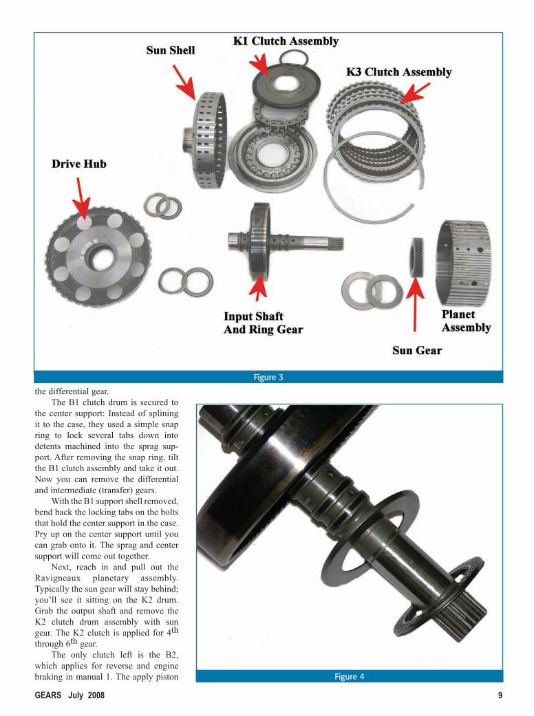
After splitting the case, all you’ll see is part of the differential and the front of the pump assembly; the rest of the transmission is still mounted inside the main part of the case. The only way to reach any of the internal components is by first removing the pump. As soon as you have the pump removed, notice that the stator is splined to the sun gear in the front planetary. This is typical for units with the Leppeletier planetary design.
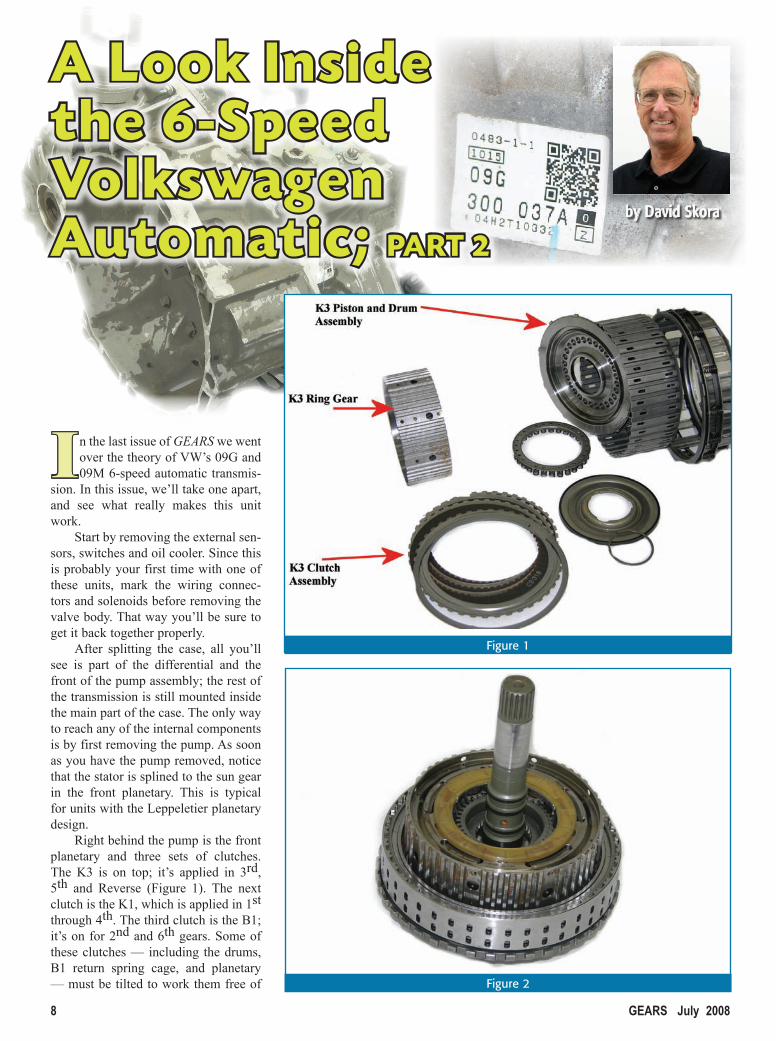
Right behind the pump is the front planetary and three sets of clutches. The K3 is on top; it’s applied in 3rd, 5th and Reverse (Figure 1). The next clutch is the K1, which is applied in 1st through 4th. The third clutch is the B1; it’s on for 2nd and 6th gears. Some of these clutches — including the drums, B1 return spring cage, and planetary — must be tilted to work them free of
Figure 1
Figure 2
GEARS July 2008 �
the differential gear.The B1 clutch drum is secured to
the center support: Instead of splining it to the case, they used a simple snap ring to lock several tabs down into detents machined into the sprag sup-port. After removing the snap ring, tilt the B1 clutch assembly and take it out. Now you can remove the differential and intermediate (transfer) gears.
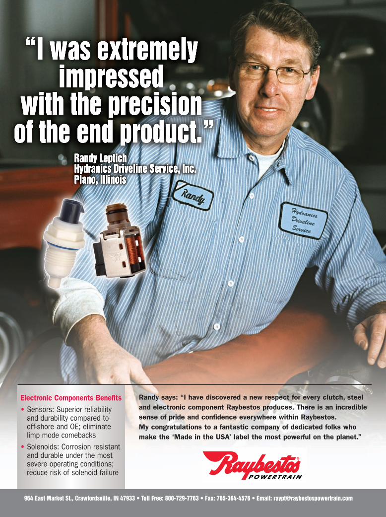
With the B1 support shell removed, bend back the locking tabs on the bolts that hold the center support in the case. Pry up on the center support until you can grab onto it. The sprag and center support will come out together.
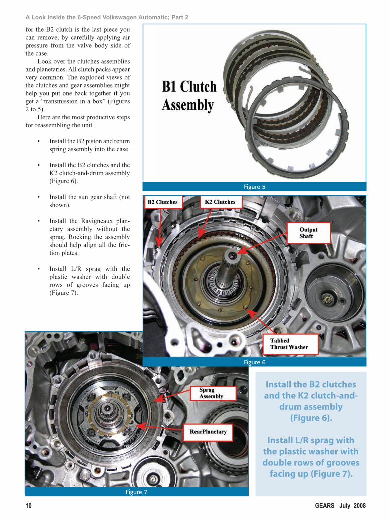
Next, reach in and pull out the Ravigneaux planetary assembly. Typically the sun gear will stay behind; you’ll see it sitting on the K2 drum. Grab the output shaft and remove the K2 clutch drum assembly with sun gear. The K2 clutch is applied for 4th through 6th gear.
The only clutch left is the B2, which applies for reverse and engine braking in manual 1. The apply piston
Figure 3
Figure 4
10 GEARSJuly2008
A Look Inside the 6-Speed Volkswagen Automatic; Part 2
Figure 5
for the B2 clutch is the last piece you can remove, by carefully applying air pressure from the valve body side of the case.
Look over the clutches assemblies and planetaries. All clutch packs appear very common. The exploded views of the clutches and gear assemblies might help you put one back together if you get a “transmission in a box” (Figures 2 to 5).
Here are the most productive steps for reassembling the unit.
• Install the B2 piston and return spring assembly into the case.
• Install the B2 clutches and the K2 clutch-and-drum assembly (Figure 6).
• Install the sun gear shaft (not shown).
• Install the Ravigneaux plan-etary assembly without the sprag. Rocking the assembly should help align all the fric-tion plates.
• Install L/R sprag with the plastic washer with double rows of grooves facing up (Figure 7).
Figure 6
Figure 7
Install the B2 clutches and the K2 clutch-and-
drum assembly (Figure 6).
Install L/R sprag with the plastic washer with double rows of grooves
facing up (Figure 7).
Randy says: “I have discovered a new respect for every clutch, steeland electronic component Raybestos produces. There is an incrediblesense of pride and confidence everywhere within Raybestos.My congratulations to a fantastic company of dedicated folks whomake the ‘Made in the USA’ label the most powerful on the planet.”
Electronic Components Benefits• Sensors: Superior reliability
and durability compared tooff-shore and OE; eliminatelimp mode comebacks
• Solenoids: Corrosion resistantand durable under the mostsevere operating conditions;reduce risk of solenoid failure
964 East Market St., Crawfordsville, IN 47933 • Toll Free: 800-729-7763 • Fax: 765-364-4576 • Email: [email protected]
RAYbestos plcd508.indd 19RAYbestos plcd508.indd 19 5/1/08 10:13:51 AM5/1/08 10:13:51 AM
12 GEARSJuly2008
A Look Inside the 6-Speed Volkswagen Automatic; Part 2
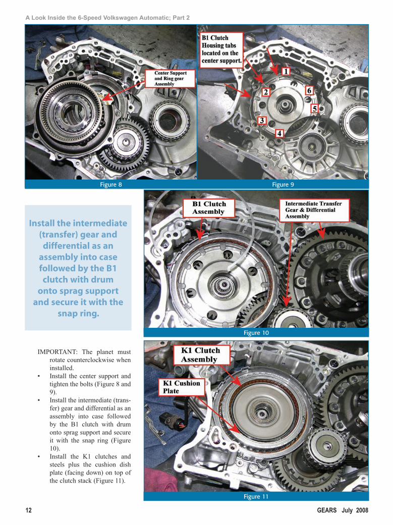
IMPORTANT: The planet must rotate counterclockwise when installed.
• Install the center support and tighten the bolts (Figure 8 and 9).
• Install the intermediate (trans-fer) gear and differential as an assembly into case followed by the B1 clutch with drum onto sprag support and secure it with the snap ring (Figure 10).
• Install the K1 clutches and steels plus the cushion dish plate (facing down) on top of the clutch stack (Figure 11).
Install the intermediate (transfer) gear and
differential as an assembly into case followed by the B1 clutch with drum
onto sprag support and secure it with the
snap ring.
Figure 10
Figure 8 Figure 9
Figure 11

Mork and Mindy are long gone, along with $2.00 movie tickets and gas at 70 cents a gallon. But TransTec® transmission kits have grown to become the leading brand requested by transmission profes-sionals. In fact, more TransTec® kits are installed than all other kits combined.
We’d like to thank our customers, representatives, suppliers and associates for their faithfulness and support throughout the past 30 years.
These years have been very good to us. We can’t wait to see what the future holds.
A Division of Freudenberg-NOK
Mork & Mindy
was a good year.1978
was aTV favorite70 cents a gallon
Gas was
A movie ticket cost $2
TransTec®kits were introduced
14 GEARSJuly2008
A Look Inside the 6-Speed Volkswagen Automatic; Part 2
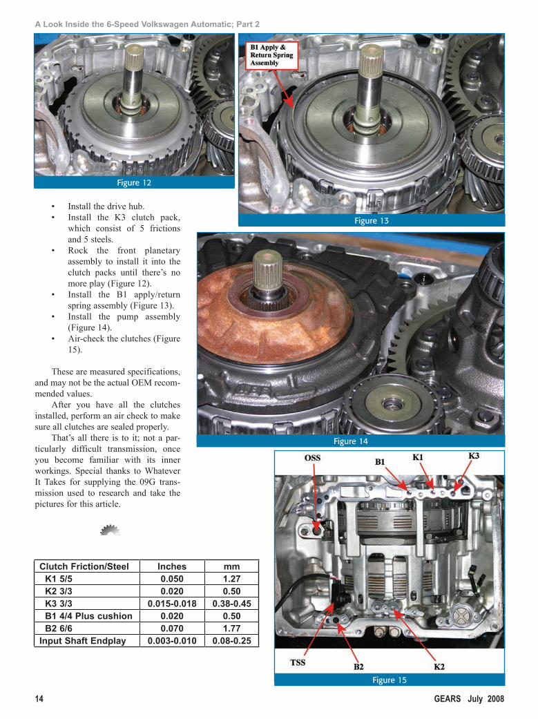
• Installthedrivehub.• Install the K3 clutch pack,
which consist of 5 frictionsand5steels.
• Rock the front planetaryassembly to install it into theclutch packs until there’s nomoreplay(Figure12).
• Install the B1 apply/returnspringassembly(Figure13).
• Install the pump assembly(Figure14).
• Air-checktheclutches(Figure15).
Thesearemeasuredspecifications,andmaynotbetheactualOEMrecom-mendedvalues.
After you have all the clutchesinstalled,performanairchecktomakesureallclutchesaresealedproperly.
That’s all there is to it; not apar-ticularly difficult transmission, onceyou become familiar with its innerworkings. Special thanks to WhateverIt Takes for supplying the 09G trans-mission used to research and take thepicturesforthisarticle.
Clutch Friction/Steel Inches mm K1 5/5 0.050 1.27 K2 3/3 0.020 0.50 K3 3/3 0.015-0.018 0.38-0.45 B1 4/4 Plus cushion 0.020 0.50 B2 6/6 0.070 1.77Input Shaft Endplay 0.003-0.010 0.08-0.25
Figure 12
Figure 14
Figure 13
Figure 15
COrrection
Cause
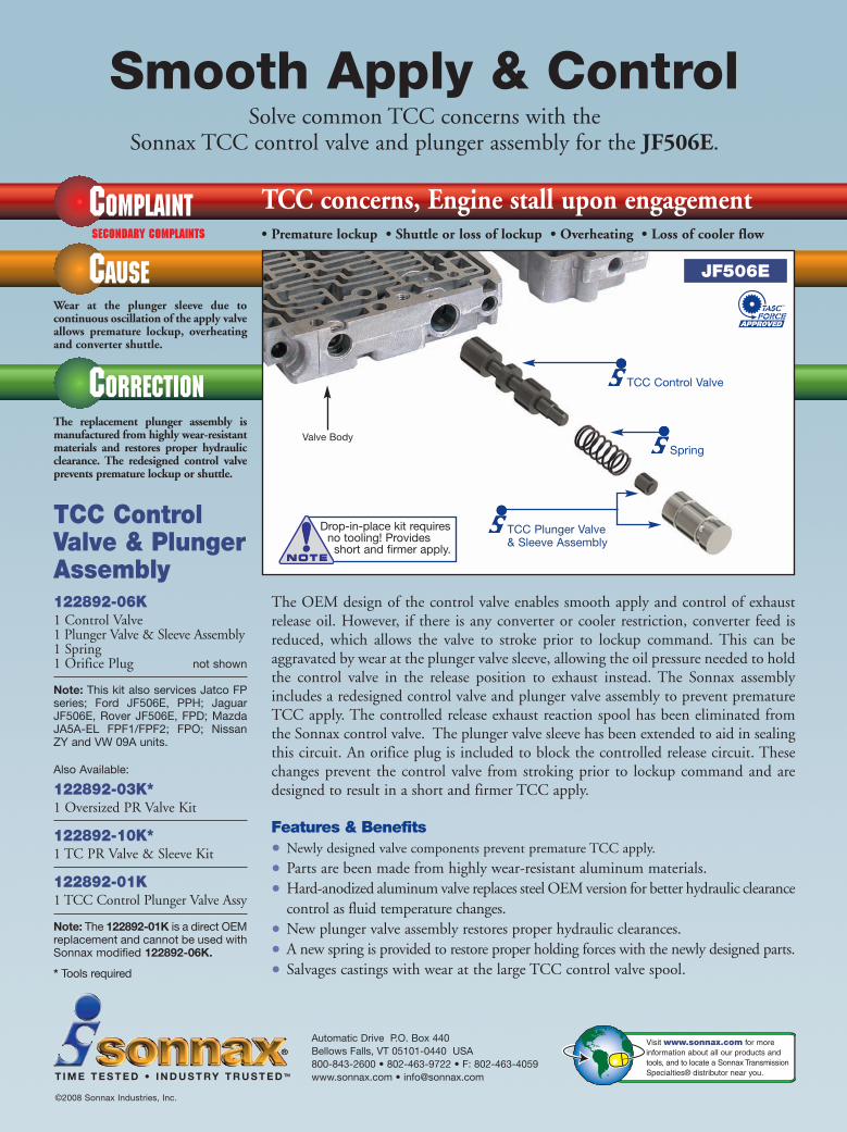
Smooth Apply & Control
COMPLAINT TCC concerns, Engine stall upon engagementSECONDARY COMPLAINTs • Premature lockup • Shuttle or loss of lockup • Overheating • Loss of cooler flow
Solve common TCC concerns with the Sonnax TCC control valve and plunger assembly for the JF506E.
Automatic Drive P.O. Box 440Bellows Falls, VT 05101-0440 USA800-843-2600 • 802-463-9722 • F: 802-463-4059www.sonnax.com • [email protected]
©2008 Sonnax Industries, Inc.
T I M E T E S T E D • I N D U S T RY T R U S T E D TM
Visit www.sonnax.com for more information about all our products andtools, and to locate a Sonnax TransmissionSpecialties® distributor near you.
Wear at the plunger sleeve due to continuous oscillation of the apply valveallows premature lockup, overheatingand converter shuttle.
The replacement plunger assembly ismanufactured from highly wear-resistantmaterials and restores proper hydraulicclearance. The redesigned control valveprevents premature lockup or shuttle.
TCC ControlValve & PlungerAssembly122892-06K1 Control Valve1 Plunger Valve & Sleeve Assembly1 Spring1 Orifice Plug not shown
Note: This kit also services Jatco FPseries; Ford JF506E, PPH; JaguarJF506E, Rover JF506E, FPD; MazdaJA5A-EL FPF1/FPF2; FPO; NissanZY and VW 09A units.
Also Available:
122892-03K*1 Oversized PR Valve Kit
122892-10K*1 TC PR Valve & Sleeve Kit
122892-01K1 TCC Control Plunger Valve Assy
Note: The 122892-01K is a direct OEMreplacement and cannot be used withSonnax modified 122892-06K.
* Tools required
JF506E
Drop-in-place kit requires no tooling! Provides
short and firmer apply.
TCC Plunger Valve & Sleeve Assembly
TCC Control Valve
Spring
The OEM design of the control valve enables smooth apply and control of exhaustrelease oil. However, if there is any converter or cooler restriction, converter feed isreduced, which allows the valve to stroke prior to lockup command. This can beaggravated by wear at the plunger valve sleeve, allowing the oil pressure needed to holdthe control valve in the release position to exhaust instead. The Sonnax assemblyincludes a redesigned control valve and plunger valve assembly to prevent prematureTCC apply. The controlled release exhaust reaction spool has been eliminated fromthe Sonnax control valve. The plunger valve sleeve has been extended to aid in sealingthis circuit. An orifice plug is included to block the controlled release circuit. Thesechanges prevent the control valve from stroking prior to lockup command and aredesigned to result in a short and firmer TCC apply.
Features & Benefits• Newly designed valve components prevent premature TCC apply.
• Parts are been made from highly wear-resistant aluminum materials.
• Hard-anodized aluminum valve replaces steel OEM version for better hydraulic clearancecontrol as fluid temperature changes.
• New plunger valve assembly restores proper hydraulic clearances.
• A new spring is provided to restore proper holding forces with the newly designed parts.
• Salvages castings with wear at the large TCC control valve spool.
Valve Body
TDIFCAD-06-08 5/9/08 11:40 AM Page 1