a lumped approach to fem modeling of loudspeaker … lumped approach to fem modeling of loudspeaker...
TRANSCRIPT

A lumped approach to FEM modeling of loudspeaker drive units
Mark DoddGP Acoustics
Research Department

Outline
• Lumped element models - overview• Finite Element methods• Lumped Finite element approach• Practical examples - Compression driver
copper sleeve & phase plug

Lumped loudspeaker models
• Simplest useful analysis
• Based on circuit analysis techniques
• Mass, spring, resistance, driving force and current-force coupler
MmsCms(x) Rms
Bl(x)
Re
v
Fm(x,I)
I
Bl(x)v Bl(x)IU
ZL(jω,x)

Lumped loudspeaker models• Very simplified & Very useful results

Non-linear Lumped loudspeaker models
• Mostly used to 'characterise' driver non-linearity using Klippel analyser
• Allow calculation of distortion
• Parameters informative large stimulus behaviour

Lumped loudspeaker models
BUT...• Can only accurately model flat rigid piston
on infinite baffle• No detailed information on shape for
magnet, suspension, membrane .........• Loudspeaker driver designers need more
detail
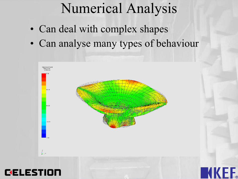
Numerical Analysis• Can deal with complex shapes• Can analyse many types of behaviour

• Acoustical • Finite & infinite regions
• Structural• Vibrational• Large Strain Problems
• Magnetic• Magneto-static• Magneto-dynamic
• Thermal
Relevant Behaviour?

Magneto-static FEM
Used for...
• Calculation of gap flux (B)
• Ensuring magnetic shielding
• Voice coil design

Magneto-Dynamic FEM
• Magneto-Dynamic FEM calculates sinusoidal electric currents coupled to magnetic flux.
• Can observe skin effect
• Calculate voltage/current for a number of frequencies
• Blocked impedance (inductive part of impedance)

Magneto-Dynamic FEM
• Permeability of steel near coil increases inductance
• Eddy currents induced – Vary strongly with frequency– Skin effect strong in steel
• Eddy currents decrease inductance
• Copper sleeves and conducting rings used to increase eddy currents & further decrease inductance

Magneto-dynamic FEM

Coupled Vibro-Acoustic FEM

Why don't we just use Multiphysics?
• Huge problem sizes & massive solution time
• Almost as hard to understand as a prototype
• Divide and conquer approach to designs• Multiple engineers can work on different aspects
• FEM to aid understanding
BUT...we still need an overview of performance.
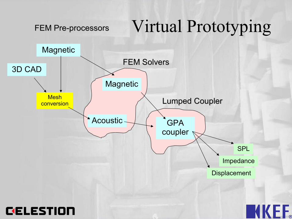
Virtual Prototyping
Magnetic
FEM SolversFEM Solvers
FEM Pre-processorsFEM Pre-processors
Lumped CouplerLumped Coupler
Magnetic
3D CAD
Mesh conversion
Acoustic GPA coupler
SPL
Impedance
Displacement
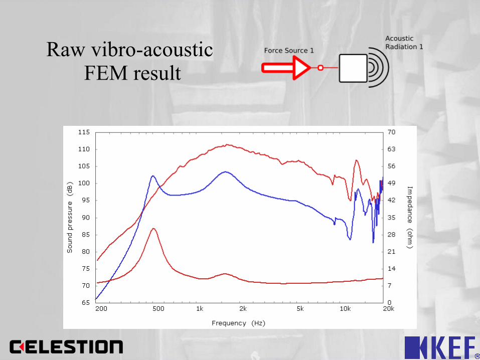
Raw vibro-acoustic FEM result

+ Static magnetic FE and coil design

+ dynamic electromagnetic FE
inductance

+ lumped mechanical
damping

+ lumped mechanical
stiffness

Practical Design based on New Methodology
F r e q u e n c y ( H z )2 0 0 5 0 0 1 k 2 k 5 k 1 0 k 2 0 k
( d B ) L e v e l , S P L
1 1 5
1 1 0
1 0 5
1 0 0
9 5
9 0
8 5
8 0
7 5
7 0
6 5
i F C : F E A - c o i l i n d u c t a n c e o f L = 0 . 0 5 4 R 2 = 2 L 2 = 0 . 2 3
F C : S P L f i n a l d e s i g n
Response on HornAir geometry

Wave Propogation at 8kHz
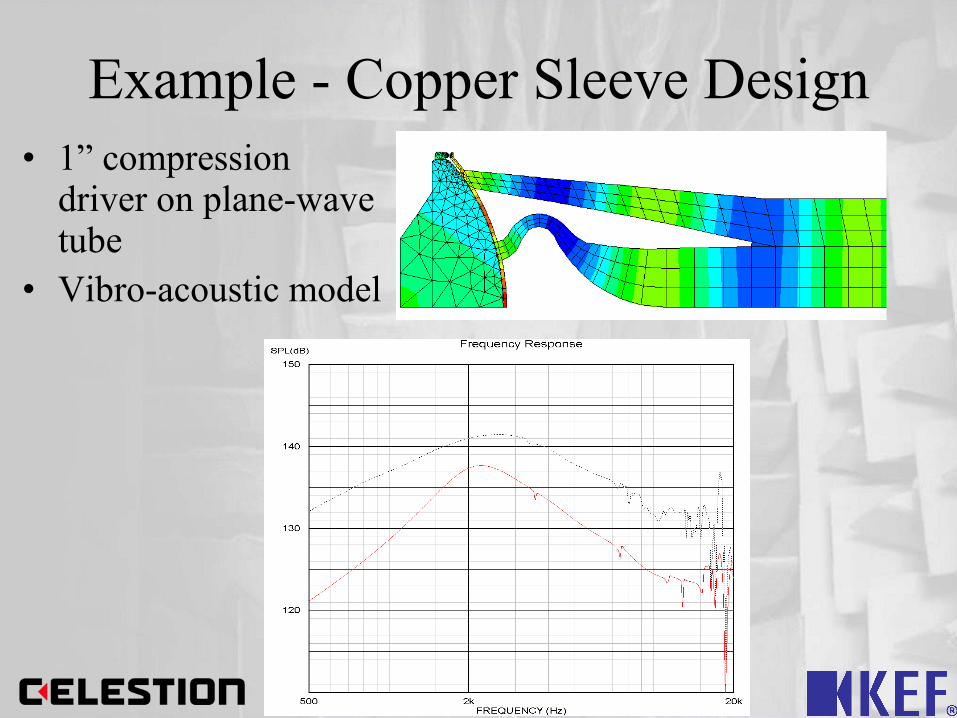
Example - Copper Sleeve Design• 1” compression
driver on plane-wave tube
• Vibro-acoustic model

Example - Copper Sleeve Design
• Using length of wire in coil
• Mean gap flux from Static Magnetic FEM
• BL=3.7

Example - Copper Sleeve Design
• Magneto Dynamic FEM calculates current in coil.
• Zb calculated with Ohms law at various frequencies

Example - Copper Sleeve Design
1000 2000 5000 10000135
140
145
150
155
160S
PL
dB
re 5
uPa
frequency Hz
cdx1425 on plane wave tube with different Cu cap thickness's
0.3mm Cu sleeve0.15mm Cu sleeve0.5mm Cu sleeve
NB; model includes coil inductance and static flux effects

• Phase-plug inner slot path shape
Example – Alternative geometries

Large strain FEM
Why do we need this kind of analysis?
• Max SPL often set by limits of driver motion
• Driver must not break, limit must be “soft”
• Instability must be avoided
• Major factor in generation of distortion

Large strain FEM

Large strain FEM

Magneto-static FEM

Magneto-dynamic FEM• Contour plots of calculated
blocked impedance
• Real and imaginary part
• Calculated for range of displacements and frequencies
4.2
3.8
3.4
3
2.6
2.2
1.8
1.4
1
0.6
0.2
Frequency, Hz50 100 200 500 1k 2k
0
-4
4
8
Dis
pla
cem
ent
mm
Impedance Real,Ohm
14
12
10
8
6
4
2
Frequency, Hz50 100 200 500 1k 2k
0
-4
4
8
Dis
pla
cem
ent m
m
Impedance imaginary, Ohm

FEM non-linear virtual prototype
• Use fem to derive Kms(x)
• Surround and suspension calculated separately and summed.

Virtual Prototyping
Magnetic
FEM SolversFEM Solvers
FEM Pre-processorsFEM Pre-processors
Lumped CouplerLumped Coupler
Magnetic
3D CAD
Mesh conversion
Acoustic GPA coupler
SPL
Impedance
Displacement
Distortion

FEM non-linear virtual prototype• Lumped non-linear model with FEM derived parameters• 90.56v.• SPL (red), 2nd harmonic (blue), 3rd harmonic (green)

Conclusions
• Simpler models clarify physics.• Simpler models solve faster but less detailed.• FEM/BEM can give fine detail and insight into
inner workings. Can take much time to set up and solve.
• FEM results much more useful when lumped
• Lumped FEM can give details of linear and non-linear behaviour

Thank You