a new mac approach in wireless body sensor networks for health care
TRANSCRIPT

A new MAC Approach in Wireless Body Sensor Networks for Health Care 91
A new MAC Approach in Wireless Body Sensor Networks for Health Care
Begonya Otal, Luis Alonso and Christos Verikoukis
X
A new MAC Approach in Wireless Body Sensor Networks for Health Care
Begonya Otal1, Luis Alonso2 and Christos Verikoukis1
1Centre Tecnològic de Telecomunicacions de Catalunya (CTTC), 2Signal Theory & Communications Dept., Universitat Politècnica de Catalunya (UPC)
Barcelona, Spain
1. Introduction
Although the challenges faced by wireless body sensor networks (BSNs) in healthcare environments are in a certain way similar to those already existing in current wireless sensor networks (WSNs), there are intrinsic differences, which require special attention (Yang, 2006). For instance, human body monitoring may be achieved by attaching sensors to the body’s surface as well as implanting them into tissues for a more accurate clinical practice. One of the major concerns is thereby that of extremely energy efficiency, which is the key to extend the lifetime of battery-powered body sensors, reduce maintenance costs and avoid invasive procedures to replace battery in the case of implantable devices. That is, BSNs in healthcare systems operate under conflicting requirements. These are the maintenance of the desired reliability and message latency of data transmissions, while simultaneously maximizing battery lifetime of individual body sensors. In doing so, the characteristics of the entire system, including physical (PHY), MAC and application (APP) layers have to be considered. In fact, the MAC layer is the one responsible for coordinating channel accesses, by avoiding collisions and scheduling data transmissions, to maximize throughput efficiency (and reliability) at an acceptable packet delay and minimal energy consumption. Now, the design of future MAC protocols for BSNs must tackle stringent quality of service (QoS) requirements, apart from the desired low power consumption. Hence, the right MAC approach is able to handle cross-layer PHY-MAC-APP features. In order to consider all the aforementioned healthcare requirements, this chapter first concentrates on the analysis and evaluation of the energy consumption in a MAC level. Thereafter, novel cross-layer fuzzy-logic techniques are proposed to enhance QoS resource management in the here portrayed MAC approach for BSNs. Simulation results are achieved to validate the overall system performance, and its scalability, by increasing the number of wireless on-body sensors in the BSN (see Fig. 1). In this context, among all IEEE 802 standards available today, the IEEE 802.15.4 (802.15.4, 2003) is regarded as the technology of choice for most BSN research studies (Yang, 2006); (Zhen et al., 2007); (Kumar et al., 2008). However, the 802.15.4 MAC is not actually intended to support any set of applications with stringent QoS, and, even though it consumes very low power, the figures do not reach the levels required in BSNs (Zhen et al., 2007); (Kumar
6
www.intechopen.com
Emerging Communications for Wireless Sensor Networks92
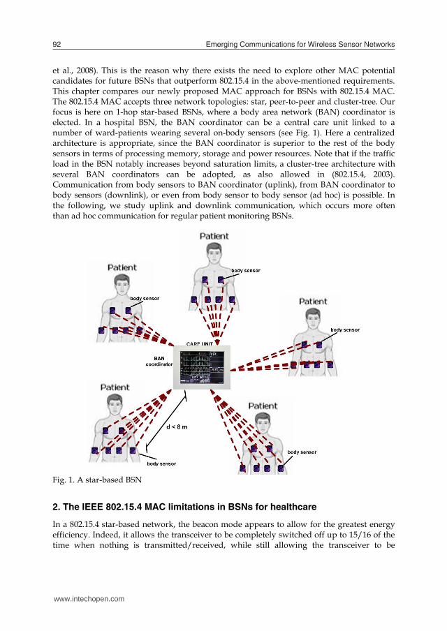
et al., 2008). This is the reason why there exists the need to explore other MAC potential candidates for future BSNs that outperform 802.15.4 in the above-mentioned requirements. This chapter compares our newly proposed MAC approach for BSNs with 802.15.4 MAC. The 802.15.4 MAC accepts three network topologies: star, peer-to-peer and cluster-tree. Our focus is here on 1-hop star-based BSNs, where a body area network (BAN) coordinator is elected. In a hospital BSN, the BAN coordinator can be a central care unit linked to a number of ward-patients wearing several on-body sensors (see Fig. 1). Here a centralized architecture is appropriate, since the BAN coordinator is superior to the rest of the body sensors in terms of processing memory, storage and power resources. Note that if the traffic load in the BSN notably increases beyond saturation limits, a cluster-tree architecture with several BAN coordinators can be adopted, as also allowed in (802.15.4, 2003). Communication from body sensors to BAN coordinator (uplink), from BAN coordinator to body sensors (downlink), or even from body sensor to body sensor (ad hoc) is possible. In the following, we study uplink and downlink communication, which occurs more often than ad hoc communication for regular patient monitoring BSNs.
Fig. 1. A star-based BSN
2. The IEEE 802.15.4 MAC limitations in BSNs for healthcare
In a 802.15.4 star-based network, the beacon mode appears to allow for the greatest energy efficiency. Indeed, it allows the transceiver to be completely switched off up to 15/16 of the time when nothing is transmitted/received, while still allowing the transceiver to be
synchronized to the network and able to transmit or receive a packet at any time (Bourgard et al., 2005). The beacon mode introduces the so-called superframe structure. The inter-beacon period is partially or entirely occupied by the superframe, which is divided into 16 slots. Among them, there are at most 7 guaranteed time slots (GTS), (i.e. they are dedicated to specific nodes), which form the contention free period (CFP) (802.15.4, 2003). This functionality targets very low latency applications, but it is not scalable in BSNs, since the number of dedicated slots is not sufficient (Zhen et al., 2007). In the medical field, where one illness usually boost-ups other illnesses, many body sensors should be able to reach the BAN coordinator via such guaranteed services. Further, the current protocol only supports first come first served based GTS allocation and does not take into account the traffic specification, delay requirements, and the energy resources. Again, in medical scenarios, many critical events may occur at a time, and some of them are more critical and need most urgent response (Kumar et al., 2008). An additional drawback with the current GTS allocation is the bandwidth under utilization. Most of the time, a device uses only a small portion of the allocated GTS slots, and the major portion remains unused, resulting in empty holes within the CFP. In such conditions, the use of the contention access period (CAP) is required; where channel accesses in the uplink are coordinated by a slotted carrier sense multiple access mechanism with collision avoidance (CSMA/CA). Nevertheless, in the literature (Bourgard et al., 2005); (Park et al., 2005); (Pollin et al., 2005), it has already been proved that the CSMA/CA mechanism has a significant negative impact on the overall energy consumption, as the traffic load in the network steadily increases. Thus, the appraisal of other existing MAC protocols in terms of delivery ratio, end-to-end delay and effective energy per information bit introduces important challenges in BSNs. That is the reason why we here introduce energy-aware radio activation policies into a high-performance MAC protocol different from CSMA/CA, while analyzing and evaluating its QoS and energy-saving performance in BSNs.
3. Overview on distributed queuing MAC protocols
This section highlights the basic features related to distributed queuing (DQ) MAC protocols that are essential for the understanding of the new QoS and energy-saving enhancements proposed in this chapter. The introduction of the Distributed Queuing Random Access Protocol (DQRAP) for local wireless communications was already presented in (Lin & Campbell, 1993) and later in (Alonso et al., 2005) under the name of Distributed Queuing Collision Avoidance (DQCA), as an adaptation to IEEE 802.11b MAC environments. It has already been shown that the throughput performance of a DQ MAC protocol outperforms CSMA/CA in all studied scenarios. The main characteristic of a DQ MAC protocol is that it behaves as a random access mechanism under low traffic conditions, and switches smoothly and automatically to a reservation scheme when the traffic load grows. That is, DQ MAC protocols show a near-optimum performance independent of the amount of active terminals and traffic load. Let us consider a star-based topology with several nodes and a network coordinator, following DQRAP original description (Xu & Campbell, 1992), the time axis is divided into an “access subslot” that is further divided into access minislots (m), and a “data subslot”. The basic idea is to concentrate user access requests in the access minislots, while the “data subslot” is devoted to collision-free data transmissions. The DQRAP analytical model
www.intechopen.com

A new MAC Approach in Wireless Body Sensor Networks for Health Care 93
et al., 2008). This is the reason why there exists the need to explore other MAC potential candidates for future BSNs that outperform 802.15.4 in the above-mentioned requirements. This chapter compares our newly proposed MAC approach for BSNs with 802.15.4 MAC. The 802.15.4 MAC accepts three network topologies: star, peer-to-peer and cluster-tree. Our focus is here on 1-hop star-based BSNs, where a body area network (BAN) coordinator is elected. In a hospital BSN, the BAN coordinator can be a central care unit linked to a number of ward-patients wearing several on-body sensors (see Fig. 1). Here a centralized architecture is appropriate, since the BAN coordinator is superior to the rest of the body sensors in terms of processing memory, storage and power resources. Note that if the traffic load in the BSN notably increases beyond saturation limits, a cluster-tree architecture with several BAN coordinators can be adopted, as also allowed in (802.15.4, 2003). Communication from body sensors to BAN coordinator (uplink), from BAN coordinator to body sensors (downlink), or even from body sensor to body sensor (ad hoc) is possible. In the following, we study uplink and downlink communication, which occurs more often than ad hoc communication for regular patient monitoring BSNs.
Fig. 1. A star-based BSN
2. The IEEE 802.15.4 MAC limitations in BSNs for healthcare
In a 802.15.4 star-based network, the beacon mode appears to allow for the greatest energy efficiency. Indeed, it allows the transceiver to be completely switched off up to 15/16 of the time when nothing is transmitted/received, while still allowing the transceiver to be
synchronized to the network and able to transmit or receive a packet at any time (Bourgard et al., 2005). The beacon mode introduces the so-called superframe structure. The inter-beacon period is partially or entirely occupied by the superframe, which is divided into 16 slots. Among them, there are at most 7 guaranteed time slots (GTS), (i.e. they are dedicated to specific nodes), which form the contention free period (CFP) (802.15.4, 2003). This functionality targets very low latency applications, but it is not scalable in BSNs, since the number of dedicated slots is not sufficient (Zhen et al., 2007). In the medical field, where one illness usually boost-ups other illnesses, many body sensors should be able to reach the BAN coordinator via such guaranteed services. Further, the current protocol only supports first come first served based GTS allocation and does not take into account the traffic specification, delay requirements, and the energy resources. Again, in medical scenarios, many critical events may occur at a time, and some of them are more critical and need most urgent response (Kumar et al., 2008). An additional drawback with the current GTS allocation is the bandwidth under utilization. Most of the time, a device uses only a small portion of the allocated GTS slots, and the major portion remains unused, resulting in empty holes within the CFP. In such conditions, the use of the contention access period (CAP) is required; where channel accesses in the uplink are coordinated by a slotted carrier sense multiple access mechanism with collision avoidance (CSMA/CA). Nevertheless, in the literature (Bourgard et al., 2005); (Park et al., 2005); (Pollin et al., 2005), it has already been proved that the CSMA/CA mechanism has a significant negative impact on the overall energy consumption, as the traffic load in the network steadily increases. Thus, the appraisal of other existing MAC protocols in terms of delivery ratio, end-to-end delay and effective energy per information bit introduces important challenges in BSNs. That is the reason why we here introduce energy-aware radio activation policies into a high-performance MAC protocol different from CSMA/CA, while analyzing and evaluating its QoS and energy-saving performance in BSNs.
3. Overview on distributed queuing MAC protocols
This section highlights the basic features related to distributed queuing (DQ) MAC protocols that are essential for the understanding of the new QoS and energy-saving enhancements proposed in this chapter. The introduction of the Distributed Queuing Random Access Protocol (DQRAP) for local wireless communications was already presented in (Lin & Campbell, 1993) and later in (Alonso et al., 2005) under the name of Distributed Queuing Collision Avoidance (DQCA), as an adaptation to IEEE 802.11b MAC environments. It has already been shown that the throughput performance of a DQ MAC protocol outperforms CSMA/CA in all studied scenarios. The main characteristic of a DQ MAC protocol is that it behaves as a random access mechanism under low traffic conditions, and switches smoothly and automatically to a reservation scheme when the traffic load grows. That is, DQ MAC protocols show a near-optimum performance independent of the amount of active terminals and traffic load. Let us consider a star-based topology with several nodes and a network coordinator, following DQRAP original description (Xu & Campbell, 1992), the time axis is divided into an “access subslot” that is further divided into access minislots (m), and a “data subslot”. The basic idea is to concentrate user access requests in the access minislots, while the “data subslot” is devoted to collision-free data transmissions. The DQRAP analytical model
www.intechopen.com

Emerging Communications for Wireless Sensor Networks94
approaches the delay and throughput performance of the theoretical optimum queuing systems M/M/1 or G/D/1, depending on the traffic distribution. Hence, DQ MAC protocols can be modelled as if every station in the system maintains two common logical distributed queues – the collision resolution queue (CRQ), and the data transmission queue (DTQ) –, physically implemented as four integers in each station; two station-dependant integers that represent the occupied position in each queue; and, two further integers shared among all stations in the system that visualize the total number of stations in each queue, CRQ and DTQ. The CRQ controls station accesses to the collision resolution server (the access minislots), while the DTQ is in charge of the data server (the “data subslot”). This provides a collision resolution tree algorithm that proves to be stable for every traffic load even over the system transmission capacity. Note that the number of access minislots is implementation dependant, but we are formally using 3 access minislots, following the original DQRAP structure and argumentation for maximizing its throughput performance (Xu & Campbell, 1992). A DQ MAC protocol consists of several strategic rules, independently performed by each station by managing the aforementioned four integers (i.e. corresponding to the two distributed queues, CRQ and DTQ) (Xu & Campbell, 1992), which answer: i) ‘who’ transmits in the data slot and ‘when’, ii) ‘who’ sends an access request sequence in the minislots (m) and ‘when’; and iii) ‘how’ to actualize their positions in the queues. Hence, the promising behaviour of DQRAP in (Lin & Campbell, 1993) ; (Xu & Campbell, 1992), and similarly of DQCA in (Alonso et al., 2005), in terms of delay and near-optimum throughput achievements (i.e. allowing high reliability), evokes the idea to further explore DQ MAC protocols in terms of energy consumption under BSN healthcare scenarios. This favourable behaviour is especially achieved thanks to the inherent protocol performance at eliminating collisions in data transmissions and minimizing the overhead of contention procedures (i.e. carrier sensing and back-off periods) with respect to CSMA/CA. Based on that, we introduce energy-efficient enhancements to allow radio activation policies and power management solutions for the proper use of DQ MAC in BSNs, while comparing it to the standard de facto (802.15.4, 2003). Additionally, we propose here a new cross-layer fuzzy-logic scheduling algorithm to improve QoS features, and by means of computer simulations, we evaluate its overall performance.
4. DQ MAC energy-saving enhancements for BSNs
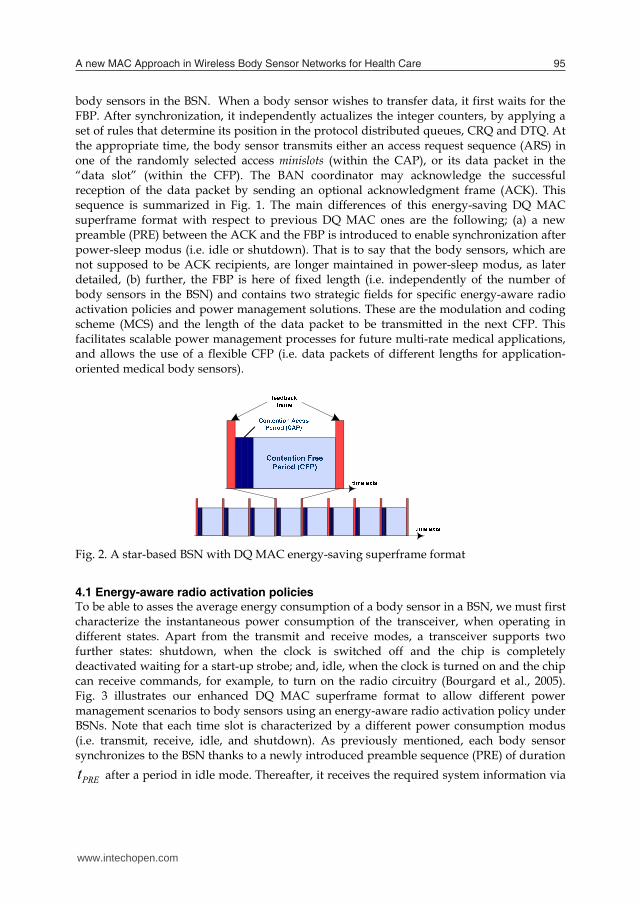
Fig. 2 shows the energy-saving superframe format of a DQ MAC protocol proposal for star-based BSNs. The complete energy-saving superframe structure comprises two differential parts; (a) from body sensors to BAN coordinator (uplink), with a CAP and a CFP. The CAP is further divided into m access minislots, whereas the CFP is devoted to collision-free data packet transmissions, and, (b) from BAN coordinator to body sensors (downlink) using the feedback frame, which contains several strategic fields. In fact, the DQ MAC superframe is bounded by the feedback packet (FBP) contained in the Fig. 2 portrayed feedback frame, which is broadcasted by the BAN coordinator. Similar to the 802.15.4 MAC superframe format, one of the main uses of the FBP is to synchronize the attached body sensors to the BAN coordinator. The FBP always contains relevant MAC control information (i.e. corresponding also to the protocol rules), which is essential for the right functioning of all
body sensors in the BSN. When a body sensor wishes to transfer data, it first waits for the FBP. After synchronization, it independently actualizes the integer counters, by applying a set of rules that determine its position in the protocol distributed queues, CRQ and DTQ. At the appropriate time, the body sensor transmits either an access request sequence (ARS) in one of the randomly selected access minislots (within the CAP), or its data packet in the “data slot” (within the CFP). The BAN coordinator may acknowledge the successful reception of the data packet by sending an optional acknowledgment frame (ACK). This sequence is summarized in Fig. 1. The main differences of this energy-saving DQ MAC superframe format with respect to previous DQ MAC ones are the following; (a) a new preamble (PRE) between the ACK and the FBP is introduced to enable synchronization after power-sleep modus (i.e. idle or shutdown). That is to say that the body sensors, which are not supposed to be ACK recipients, are longer maintained in power-sleep modus, as later detailed, (b) further, the FBP is here of fixed length (i.e. independently of the number of body sensors in the BSN) and contains two strategic fields for specific energy-aware radio activation policies and power management solutions. These are the modulation and coding scheme (MCS) and the length of the data packet to be transmitted in the next CFP. This facilitates scalable power management processes for future multi-rate medical applications, and allows the use of a flexible CFP (i.e. data packets of different lengths for application-oriented medical body sensors).
Fig. 2. A star-based BSN with DQ MAC energy-saving superframe format
4.1 Energy-aware radio activation policies To be able to asses the average energy consumption of a body sensor in a BSN, we must first characterize the instantaneous power consumption of the transceiver, when operating in different states. Apart from the transmit and receive modes, a transceiver supports two further states: shutdown, when the clock is switched off and the chip is completely deactivated waiting for a start-up strobe; and, idle, when the clock is turned on and the chip can receive commands, for example, to turn on the radio circuitry (Bourgard et al., 2005). Fig. 3 illustrates our enhanced DQ MAC superframe format to allow different power management scenarios to body sensors using an energy-aware radio activation policy under BSNs. Note that each time slot is characterized by a different power consumption modus (i.e. transmit, receive, idle, and shutdown). As previously mentioned, each body sensor synchronizes to the BSN thanks to a newly introduced preamble sequence (PRE) of duration
PREt after a period in idle mode. Thereafter, it receives the required system information via
www.intechopen.com
A new MAC Approach in Wireless Body Sensor Networks for Health Care 95
approaches the delay and throughput performance of the theoretical optimum queuing systems M/M/1 or G/D/1, depending on the traffic distribution. Hence, DQ MAC protocols can be modelled as if every station in the system maintains two common logical distributed queues – the collision resolution queue (CRQ), and the data transmission queue (DTQ) –, physically implemented as four integers in each station; two station-dependant integers that represent the occupied position in each queue; and, two further integers shared among all stations in the system that visualize the total number of stations in each queue, CRQ and DTQ. The CRQ controls station accesses to the collision resolution server (the access minislots), while the DTQ is in charge of the data server (the “data subslot”). This provides a collision resolution tree algorithm that proves to be stable for every traffic load even over the system transmission capacity. Note that the number of access minislots is implementation dependant, but we are formally using 3 access minislots, following the original DQRAP structure and argumentation for maximizing its throughput performance (Xu & Campbell, 1992). A DQ MAC protocol consists of several strategic rules, independently performed by each station by managing the aforementioned four integers (i.e. corresponding to the two distributed queues, CRQ and DTQ) (Xu & Campbell, 1992), which answer: i) ‘who’ transmits in the data slot and ‘when’, ii) ‘who’ sends an access request sequence in the minislots (m) and ‘when’; and iii) ‘how’ to actualize their positions in the queues. Hence, the promising behaviour of DQRAP in (Lin & Campbell, 1993) ; (Xu & Campbell, 1992), and similarly of DQCA in (Alonso et al., 2005), in terms of delay and near-optimum throughput achievements (i.e. allowing high reliability), evokes the idea to further explore DQ MAC protocols in terms of energy consumption under BSN healthcare scenarios. This favourable behaviour is especially achieved thanks to the inherent protocol performance at eliminating collisions in data transmissions and minimizing the overhead of contention procedures (i.e. carrier sensing and back-off periods) with respect to CSMA/CA. Based on that, we introduce energy-efficient enhancements to allow radio activation policies and power management solutions for the proper use of DQ MAC in BSNs, while comparing it to the standard de facto (802.15.4, 2003). Additionally, we propose here a new cross-layer fuzzy-logic scheduling algorithm to improve QoS features, and by means of computer simulations, we evaluate its overall performance.
4. DQ MAC energy-saving enhancements for BSNs
Fig. 2 shows the energy-saving superframe format of a DQ MAC protocol proposal for star-based BSNs. The complete energy-saving superframe structure comprises two differential parts; (a) from body sensors to BAN coordinator (uplink), with a CAP and a CFP. The CAP is further divided into m access minislots, whereas the CFP is devoted to collision-free data packet transmissions, and, (b) from BAN coordinator to body sensors (downlink) using the feedback frame, which contains several strategic fields. In fact, the DQ MAC superframe is bounded by the feedback packet (FBP) contained in the Fig. 2 portrayed feedback frame, which is broadcasted by the BAN coordinator. Similar to the 802.15.4 MAC superframe format, one of the main uses of the FBP is to synchronize the attached body sensors to the BAN coordinator. The FBP always contains relevant MAC control information (i.e. corresponding also to the protocol rules), which is essential for the right functioning of all
body sensors in the BSN. When a body sensor wishes to transfer data, it first waits for the FBP. After synchronization, it independently actualizes the integer counters, by applying a set of rules that determine its position in the protocol distributed queues, CRQ and DTQ. At the appropriate time, the body sensor transmits either an access request sequence (ARS) in one of the randomly selected access minislots (within the CAP), or its data packet in the “data slot” (within the CFP). The BAN coordinator may acknowledge the successful reception of the data packet by sending an optional acknowledgment frame (ACK). This sequence is summarized in Fig. 1. The main differences of this energy-saving DQ MAC superframe format with respect to previous DQ MAC ones are the following; (a) a new preamble (PRE) between the ACK and the FBP is introduced to enable synchronization after power-sleep modus (i.e. idle or shutdown). That is to say that the body sensors, which are not supposed to be ACK recipients, are longer maintained in power-sleep modus, as later detailed, (b) further, the FBP is here of fixed length (i.e. independently of the number of body sensors in the BSN) and contains two strategic fields for specific energy-aware radio activation policies and power management solutions. These are the modulation and coding scheme (MCS) and the length of the data packet to be transmitted in the next CFP. This facilitates scalable power management processes for future multi-rate medical applications, and allows the use of a flexible CFP (i.e. data packets of different lengths for application-oriented medical body sensors).
Fig. 2. A star-based BSN with DQ MAC energy-saving superframe format
4.1 Energy-aware radio activation policies To be able to asses the average energy consumption of a body sensor in a BSN, we must first characterize the instantaneous power consumption of the transceiver, when operating in different states. Apart from the transmit and receive modes, a transceiver supports two further states: shutdown, when the clock is switched off and the chip is completely deactivated waiting for a start-up strobe; and, idle, when the clock is turned on and the chip can receive commands, for example, to turn on the radio circuitry (Bourgard et al., 2005). Fig. 3 illustrates our enhanced DQ MAC superframe format to allow different power management scenarios to body sensors using an energy-aware radio activation policy under BSNs. Note that each time slot is characterized by a different power consumption modus (i.e. transmit, receive, idle, and shutdown). As previously mentioned, each body sensor synchronizes to the BSN thanks to a newly introduced preamble sequence (PRE) of duration
PREt after a period in idle mode. Thereafter, it receives the required system information via
www.intechopen.com

Emerging Communications for Wireless Sensor Networks96
the FBP of duration FBPt for updating the distributed queues, CRQ and DTQ (Xu & Campbell,
1992). After each FBP, a short inter-frame space IFSt is left to allow the MAC layer to process the data received from the PHY layer, like in (802.15.4, 2003). Active body sensors involved in the access procedure like in scenarios (1) and (2) start by sending an ARS, here of duration length
ARSt , in one of the randomly selected access minislots (Alonso et al., 2005). Prior to that, these body sensors should have switched its radio from idle to transmit mode, which take them a transition time iat for body sensor radio wake-up (i.e. from idle to active modes (Bourgard et al., 2005)). Next, scenario (3) depicts the transmission of a previously granted packet of average duration length DATAt preceded by the transition time iat . If the packet is received correctly, an
acknowledgement (ACK) of duration ACKt is sent back to the transmitting body sensor followed
by the FBP (and PRE) after a maximum time aw ACKt t , during which the receiver turns its
radio to idle mode to save energy. In (802.15.4, 2003), awt is characterized as the maximum time to wait for an ACK. Scenario (4) shows how an active body sensor waiting in idle mode synchronizes through the PRE to receive the FBP. Finally, scenario (5) portrays how a body sensor in shutdown state wakes up and waits for some time in idle mode to synchronize through the PRE and get the FBP to update the state of the CRQ and DTQ queues (see Section 3).
Fig. 3. Power management scenarios in BSNs
4.2 Energy-efficiency analysis Let us now define , tx rxP P and idleP as the power consumption in transmit, receive and idle
modes respectively, and similarly, , tx rxT T and idleT , as the average time a body sensor spends in each of the aforementioned modes within the queuing system (i.e. CRQ and DTQ). Thus, the average consumed energy per information bit for every active body sensor in the BSN can be expressed as
bit FRAME bitE E L , where bitL corresponds to the payload data
length in bits, and FRAMEE to
.
FRAME tx tx rx rx idle idleE P T P T P T (1)
The average time in transmit, receive and idle mode can be computed as,
( ) ,( ) ,
[ ( )].
tx tx ARS ia DATA ia
rx waiting PRE FBP ia ACK
idle waiting FRAME PRE FBP
T n t t t tT n t t t t
T n T t t
(2)
The average duration of the DQ MAC time superframe, FRAMET , derived from Fig. 2 is characterized as,
,FRAME ARS DATA aw PRE FBP IFST m t t t t t t (3) where m corresponds to the number of minislots used in the current DQ MAC superframe structure, and ARSt , DATAt , awt , ACKt , PREt , FBPt , IFSt and iat have been previously defined following the illustration example of power management scenarios in Fig. 2. Here, we specify waitingn and txn , as the total average number of slot time frames waiting in the
whole queuing system (i.e. CRQ and DTQ), and, the average number of slot time frames used to transmit an ARS in the CRQ system, respectively. Their concrete characterization is not straightforward, but both numbers can be derived from DQRAP original delay theoretical analysis in (Zhang & Campbell, 1993). Fig. 4(a) portrays the analytical results of the energy consumption per information bit of DQ MAC versus the theoretical analysis of 802.15.4 MAC in (Bourgard et al., 2005), as the relative traffic load in the BSN increases. It can be seen, that the use of DQ MAC outperforms 802.15.4 MAC by reducing a 37% the energy consumption per information bit, when the relative traffic load is as high as 60%. The here presented DQ MAC energy-efficient analysis is corroborated by computer simulations in Fig. 4(b) and its description follows.
4.3 Energy-efficiency evaluation The performance of the studied energy-efficiency analysis is validated via MATLAB computer simulations, by implementing the DQ MAC protocol (see Section 3), within a star-based BSN scenario, as the relative traffic load increases until saturation conditions. Relative traffic load is here defined, as the ratio of generated data packets per iteration. The traffic load rises by increasing the number of active body sensors in the BSN in each simulation. Note that all body sensors follow a Poisson traffic distribution, since we consider here a
www.intechopen.com

A new MAC Approach in Wireless Body Sensor Networks for Health Care 97
the FBP of duration FBPt for updating the distributed queues, CRQ and DTQ (Xu & Campbell,
1992). After each FBP, a short inter-frame space IFSt is left to allow the MAC layer to process the data received from the PHY layer, like in (802.15.4, 2003). Active body sensors involved in the access procedure like in scenarios (1) and (2) start by sending an ARS, here of duration length
ARSt , in one of the randomly selected access minislots (Alonso et al., 2005). Prior to that, these body sensors should have switched its radio from idle to transmit mode, which take them a transition time iat for body sensor radio wake-up (i.e. from idle to active modes (Bourgard et al., 2005)). Next, scenario (3) depicts the transmission of a previously granted packet of average duration length DATAt preceded by the transition time iat . If the packet is received correctly, an
acknowledgement (ACK) of duration ACKt is sent back to the transmitting body sensor followed
by the FBP (and PRE) after a maximum time aw ACKt t , during which the receiver turns its
radio to idle mode to save energy. In (802.15.4, 2003), awt is characterized as the maximum time to wait for an ACK. Scenario (4) shows how an active body sensor waiting in idle mode synchronizes through the PRE to receive the FBP. Finally, scenario (5) portrays how a body sensor in shutdown state wakes up and waits for some time in idle mode to synchronize through the PRE and get the FBP to update the state of the CRQ and DTQ queues (see Section 3).
Fig. 3. Power management scenarios in BSNs
4.2 Energy-efficiency analysis Let us now define , tx rxP P and idleP as the power consumption in transmit, receive and idle
modes respectively, and similarly, , tx rxT T and idleT , as the average time a body sensor spends in each of the aforementioned modes within the queuing system (i.e. CRQ and DTQ). Thus, the average consumed energy per information bit for every active body sensor in the BSN can be expressed as
bit FRAME bitE E L , where bitL corresponds to the payload data
length in bits, and FRAMEE to
.
FRAME tx tx rx rx idle idleE P T P T P T (1)
The average time in transmit, receive and idle mode can be computed as,
( ) ,( ) ,
[ ( )].
tx tx ARS ia DATA ia
rx waiting PRE FBP ia ACK
idle waiting FRAME PRE FBP
T n t t t tT n t t t t
T n T t t
(2)
The average duration of the DQ MAC time superframe, FRAMET , derived from Fig. 2 is characterized as,
,FRAME ARS DATA aw PRE FBP IFST m t t t t t t (3) where m corresponds to the number of minislots used in the current DQ MAC superframe structure, and ARSt , DATAt , awt , ACKt , PREt , FBPt , IFSt and iat have been previously defined following the illustration example of power management scenarios in Fig. 2. Here, we specify waitingn and txn , as the total average number of slot time frames waiting in the
whole queuing system (i.e. CRQ and DTQ), and, the average number of slot time frames used to transmit an ARS in the CRQ system, respectively. Their concrete characterization is not straightforward, but both numbers can be derived from DQRAP original delay theoretical analysis in (Zhang & Campbell, 1993). Fig. 4(a) portrays the analytical results of the energy consumption per information bit of DQ MAC versus the theoretical analysis of 802.15.4 MAC in (Bourgard et al., 2005), as the relative traffic load in the BSN increases. It can be seen, that the use of DQ MAC outperforms 802.15.4 MAC by reducing a 37% the energy consumption per information bit, when the relative traffic load is as high as 60%. The here presented DQ MAC energy-efficient analysis is corroborated by computer simulations in Fig. 4(b) and its description follows.
4.3 Energy-efficiency evaluation The performance of the studied energy-efficiency analysis is validated via MATLAB computer simulations, by implementing the DQ MAC protocol (see Section 3), within a star-based BSN scenario, as the relative traffic load increases until saturation conditions. Relative traffic load is here defined, as the ratio of generated data packets per iteration. The traffic load rises by increasing the number of active body sensors in the BSN in each simulation. Note that all body sensors follow a Poisson traffic distribution, since we consider here a
www.intechopen.com

Emerging Communications for Wireless Sensor Networks98
generalized case scenario. The energy consumption is computed considering every body sensor spent time and power consumption in each of the aforementioned states (i.e. transmit, receive and idle) following DQ MAC procedure in our simulated BSN scenario. Thus, the energy consumption per information bit is defined as the ratio of the total energy consumption per body sensor and per payload packet length (i.e. information bit). Every active body sensor is supposedly located at a random distance from the BAN coordinator, as portrayed in Fig.1. The channel link implementation is based on the path loss model of (802.15.4, 2003), where the average received power is expressed as a function of an arbitrary T–R separation distance of maximum 8 meters (i.e. within a hospital setting). In our simulations, the time-variant received signal also includes Additive White Gaussian Noise (AWGN) and the effect of log-normal shadowing, assuming the channel is coherent within the transmission of a DQ MAC superframe, like in indoor environments. The reference BSN scenario is characterised by the system parameters corresponding to the standardized 802.15.4 MAC default values in the upper frequency band 2.4 GHz at the fixed data rate 250 Kb/s (802.15.4, 2003). Following the illustration of DQ MAC superframe structure in Fig. 2, we choose the longest data payload lengths (L) of 80, 100 and 120 bytes, to minimize the PHY (6 bytes) and MAC (8 bytes) headers overhead per information bit. Further, a packet may be corrupted by bit errors due to noise. Hence, a body sensor waits for an ACK (11 bytes) for a maximum time of aw ACKt t , where awt is limited to 864 μs, as defined in (802.15.4, 2003). The synchronization PRE corresponds to 4 bytes and it is followed by the FBP of 11 bytes, similar to a beacon (802.15.4, 2003). Additionally, we use 3 access minislots, like in the literature (Xu & Campbell, 1992), and an ARS occupies hereby the same size as a preamble sequence (i.e. 4 bytes), which is a worst case assumption. Power consumption values are formalized as in (Bourgard et al., 2005), (i.e. rxP = 35.28 mW, idleP = 712 μW, and,
txP = 22.09 mW, for a transmit power of -5 dBm). The analytical and simulated results of DQ MAC energy consumption per information bit are depicted in Fig. 4(b). (a) (b) Fig. 4(a). Energy consumption per information bit – Analytical results DQ vs. 802.15.4 MAC
(b). DQ MAC energy consumption per information bit – Analytical vs. Simulated Here, it can be seen the excellent protocol performance even for the highest traffic load between 80% and 90%, which remains under 350 nJ/bit. Thus, the simulation results corroborate the accuracy of the newly introduced theoretical analysis in terms of energy efficiency. They also show the appropriate scalability of DQ MAC energy-saving performance for future BSN scenarios, while fulfilling healthcare stringent power consumption requirements 5. New DQBAN system modelling for QoS
Up to now, we mainly tackled energy-consumption per information bit and presented an enhanced energy-saving DQ MAC solution as a potential candidate to overcome 802.15.4 MAC deficit figures required in BSNs. However, the design of future MAC protocols for BSNs must also fulfill other stringent requirements, such as high reliability, fairness and low latency (i.e. QoS), apart from the desired low power consumption. For that purpose, a novel cross-layer fuzzy-rule scheduling algorithm is introduced for the first time within the use of a DQ MAC protocol (Otal et al., 2009). This operates on top of the energy-aware radio activation policies previously presented. The main idea hereby is to integrate a fuzzy-logic system in each body sensor to deal with multiple cross-layer input variables of diverse nature in an independent manner. By being autonomously aware of their current condition and specific medical requirements, body sensors are able to demand a “collision-free” time slot, whenever they consider it strictly necessarily (e.g. high system packet delay or low body sensor residual battery lifetime). Similarly, they may refuse to transmit, if there is a bad channel link, thus permitting another body sensor to do so. This results in improving the system overall performance, while keeping the inherent distributed behavior of a DQ MAC protocol. Hence, the here proposed Distributed Queuing Body Area Network (DQBAN) protocol is an alternative enhancement to 802.15.4 MAC in all possible BSN scenarios. DQBAN corresponds to an enhanced MAC model specially modified by means of a novel cross-layer fuzzy-logic scheduling mechanism on top of the above described energy-aware activation policies to satisfy energy-efficient and stringent QoS demands in healthcare scenarios. Hence, DQBAN supports high application-dependant performance requirements in terms of reliability, message latency and power consumption, while being adaptable to changing conditions, such as heterogeneous traffic load, interferences, and the number of sensors in a hospital BSN. DQBAN also utilizes the two common logical distributed queues CRQ and DTQ, for serving access requests (via the “access minislots”) and data packets (via the “data slot”), respectively. In the new logic system model though, instead of keeping a first-come-first-served discipline in DTQ, a cross-layer fuzzy-rule based scheduler is introduced, as portrayed in Fig. 5. The use of the scheduler permits a body sensor, though not occupying the first position in DTQ, to transmit its data in the next frame collision-free “data slot” in order to achieve a far more reliable system performance for medical applications. Practically speaking, this is obtained by integrating a fuzzy-logic system in each body sensor in the BSN. As explained later, a fuzzy-logic approach allows each particular body sensor to individually deal with multiple cross-layer inputs of diverse nature (i.e. x1, x2, to xk in Fig. 4). The basic idea is that body sensors consider their own QoS criteria, current channel
www.intechopen.com

A new MAC Approach in Wireless Body Sensor Networks for Health Care 99
generalized case scenario. The energy consumption is computed considering every body sensor spent time and power consumption in each of the aforementioned states (i.e. transmit, receive and idle) following DQ MAC procedure in our simulated BSN scenario. Thus, the energy consumption per information bit is defined as the ratio of the total energy consumption per body sensor and per payload packet length (i.e. information bit). Every active body sensor is supposedly located at a random distance from the BAN coordinator, as portrayed in Fig.1. The channel link implementation is based on the path loss model of (802.15.4, 2003), where the average received power is expressed as a function of an arbitrary T–R separation distance of maximum 8 meters (i.e. within a hospital setting). In our simulations, the time-variant received signal also includes Additive White Gaussian Noise (AWGN) and the effect of log-normal shadowing, assuming the channel is coherent within the transmission of a DQ MAC superframe, like in indoor environments. The reference BSN scenario is characterised by the system parameters corresponding to the standardized 802.15.4 MAC default values in the upper frequency band 2.4 GHz at the fixed data rate 250 Kb/s (802.15.4, 2003). Following the illustration of DQ MAC superframe structure in Fig. 2, we choose the longest data payload lengths (L) of 80, 100 and 120 bytes, to minimize the PHY (6 bytes) and MAC (8 bytes) headers overhead per information bit. Further, a packet may be corrupted by bit errors due to noise. Hence, a body sensor waits for an ACK (11 bytes) for a maximum time of aw ACKt t , where awt is limited to 864 μs, as defined in (802.15.4, 2003). The synchronization PRE corresponds to 4 bytes and it is followed by the FBP of 11 bytes, similar to a beacon (802.15.4, 2003). Additionally, we use 3 access minislots, like in the literature (Xu & Campbell, 1992), and an ARS occupies hereby the same size as a preamble sequence (i.e. 4 bytes), which is a worst case assumption. Power consumption values are formalized as in (Bourgard et al., 2005), (i.e. rxP = 35.28 mW, idleP = 712 μW, and,
txP = 22.09 mW, for a transmit power of -5 dBm). The analytical and simulated results of DQ MAC energy consumption per information bit are depicted in Fig. 4(b). (a) (b) Fig. 4(a). Energy consumption per information bit – Analytical results DQ vs. 802.15.4 MAC
(b). DQ MAC energy consumption per information bit – Analytical vs. Simulated Here, it can be seen the excellent protocol performance even for the highest traffic load between 80% and 90%, which remains under 350 nJ/bit. Thus, the simulation results corroborate the accuracy of the newly introduced theoretical analysis in terms of energy efficiency. They also show the appropriate scalability of DQ MAC energy-saving performance for future BSN scenarios, while fulfilling healthcare stringent power consumption requirements 5. New DQBAN system modelling for QoS
Up to now, we mainly tackled energy-consumption per information bit and presented an enhanced energy-saving DQ MAC solution as a potential candidate to overcome 802.15.4 MAC deficit figures required in BSNs. However, the design of future MAC protocols for BSNs must also fulfill other stringent requirements, such as high reliability, fairness and low latency (i.e. QoS), apart from the desired low power consumption. For that purpose, a novel cross-layer fuzzy-rule scheduling algorithm is introduced for the first time within the use of a DQ MAC protocol (Otal et al., 2009). This operates on top of the energy-aware radio activation policies previously presented. The main idea hereby is to integrate a fuzzy-logic system in each body sensor to deal with multiple cross-layer input variables of diverse nature in an independent manner. By being autonomously aware of their current condition and specific medical requirements, body sensors are able to demand a “collision-free” time slot, whenever they consider it strictly necessarily (e.g. high system packet delay or low body sensor residual battery lifetime). Similarly, they may refuse to transmit, if there is a bad channel link, thus permitting another body sensor to do so. This results in improving the system overall performance, while keeping the inherent distributed behavior of a DQ MAC protocol. Hence, the here proposed Distributed Queuing Body Area Network (DQBAN) protocol is an alternative enhancement to 802.15.4 MAC in all possible BSN scenarios. DQBAN corresponds to an enhanced MAC model specially modified by means of a novel cross-layer fuzzy-logic scheduling mechanism on top of the above described energy-aware activation policies to satisfy energy-efficient and stringent QoS demands in healthcare scenarios. Hence, DQBAN supports high application-dependant performance requirements in terms of reliability, message latency and power consumption, while being adaptable to changing conditions, such as heterogeneous traffic load, interferences, and the number of sensors in a hospital BSN. DQBAN also utilizes the two common logical distributed queues CRQ and DTQ, for serving access requests (via the “access minislots”) and data packets (via the “data slot”), respectively. In the new logic system model though, instead of keeping a first-come-first-served discipline in DTQ, a cross-layer fuzzy-rule based scheduler is introduced, as portrayed in Fig. 5. The use of the scheduler permits a body sensor, though not occupying the first position in DTQ, to transmit its data in the next frame collision-free “data slot” in order to achieve a far more reliable system performance for medical applications. Practically speaking, this is obtained by integrating a fuzzy-logic system in each body sensor in the BSN. As explained later, a fuzzy-logic approach allows each particular body sensor to individually deal with multiple cross-layer inputs of diverse nature (i.e. x1, x2, to xk in Fig. 4). The basic idea is that body sensors consider their own QoS criteria, current channel
www.intechopen.com

Emerging Communications for Wireless Sensor Networks100
quality and battery constraints, and make use of fuzzy-logic theory, as a control mechanism, to demand or refuse the next frame “data slot”, according to their particular needs.
Fig. 5. New DQBAN logic system model
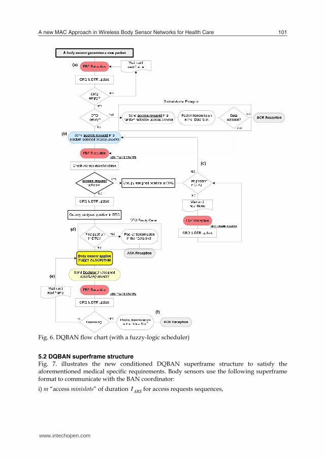
5.1 DQBAN body sensor flow chart As illustrated in the DQBAN flow chart of Fig. 6 a body sensor willing to transmit a packet must first synchronize with the BAN coordinator through the broadcasted FBP to update the state of the system queues (CRQ & DTQ) (see Fig. 6,(a)). Note that when both queues are empty, the protocol uses an exception of slotted-Aloha (Xu & Campbell, 1992). However, if CRQ is empty – but DTQ is not –, the body sensor sends an access request – randomly selecting one of the “access minislots” – to grant its access into DTQ (see Fig. 6,(b)). If its access request collides with any of another body sensor in the selected “access minislot”, these body sensors involved therein occupy the same position in CRQ (following the order of the selected minislot position), and wait for a future frame to compete for a free “access minislot” again to grant its access into a DTQ exclusive position. New body sensors, with a packet to send, are not allowed to enter the system until CRQ is empty (i.e. all current collisions are resolved) (see Fig. 6,(c)). When a body sensor selects successfully a free “access minislot” (known at the reception of the FBP), it takes immediately a place in DTQ up. If DTQ is now empty, it may be in the first position of DTQ, thus transmitting directly in the next DQBAN superframe “data slot” (see Fig. 6,(d)), DTQ Empty Case). If this is not the case, each body sensor applies its fuzzy-logic algorithm in order to demand a collision-free “data slot” (i.e. to be forwarded) or to refuse the next “data slot” (i.e. to be delayed) whenever it is required. As explained in the next section, this algorithm consists of a number of fuzzy-logic rules, which permit body sensors to find out ‘how favorable’ or ‘how critical’ their specific situation is, in a particular time frame. Every body sensor in DTQ has the chance to individually send its Decision (i.e. forward or delay) to the BAN coordinator via the “scheduling minislots”. Otherwise, it remains in the same position and no decision is sent to the BAN coordinator. When having all different results, the BAN coordinator notifies — through the broadcasted FBP — about the specific changes to improve the system overall performance: i) if a body sensor requires the next collision-free “data slot”, or ii) if a body sensor in the position to transmit indicated its refusal to do so (see Fig. 6,(e)). Upon reception of the FBP, each body sensor knows whether it may transmit in the next “data slot” or not, and updates the queue states consequently (see (Lin & Campbell, 1993); (Xu & Campbell, 1992)). Finally, the turn comes for the body sensor to transmit and wait for the reception of an ACK from the BAN coordinator (see Fig. 6, (f)).
Fig. 6. DQBAN flow chart (with a fuzzy-logic scheduler)
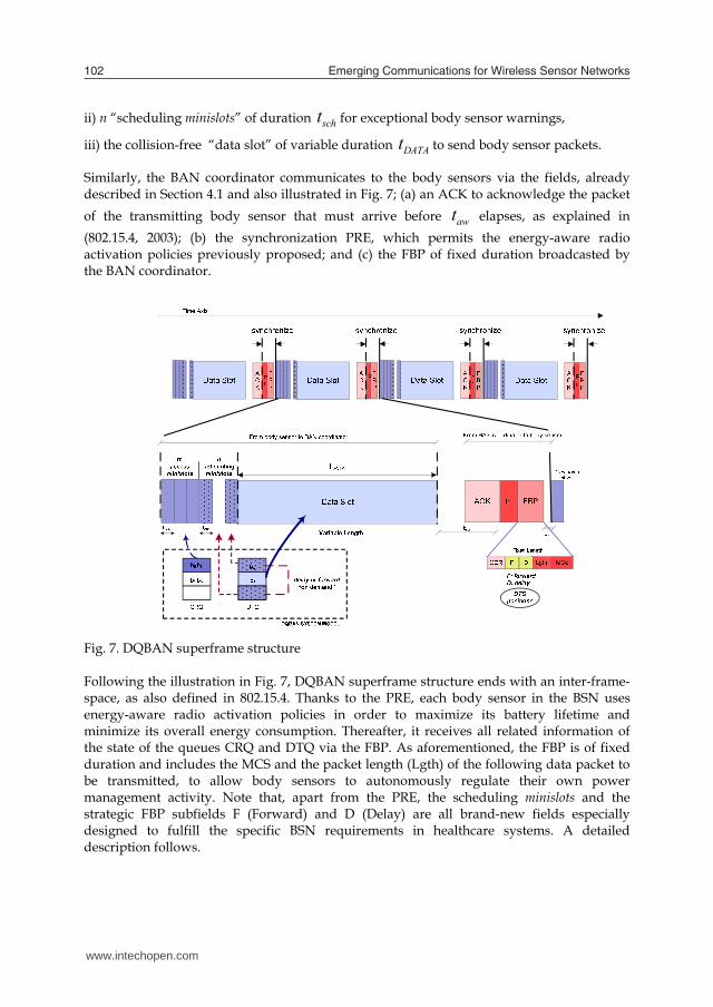
5.2 DQBAN superframe structure Fig. 7. illustrates the new conditioned DQBAN superframe structure to satisfy the aforementioned medical specific requirements. Body sensors use the following superframe format to communicate with the BAN coordinator: i) m “access minislots” of duration ARSt for access requests sequences,
www.intechopen.com
A new MAC Approach in Wireless Body Sensor Networks for Health Care 101
quality and battery constraints, and make use of fuzzy-logic theory, as a control mechanism, to demand or refuse the next frame “data slot”, according to their particular needs.
Fig. 5. New DQBAN logic system model
5.1 DQBAN body sensor flow chart As illustrated in the DQBAN flow chart of Fig. 6 a body sensor willing to transmit a packet must first synchronize with the BAN coordinator through the broadcasted FBP to update the state of the system queues (CRQ & DTQ) (see Fig. 6,(a)). Note that when both queues are empty, the protocol uses an exception of slotted-Aloha (Xu & Campbell, 1992). However, if CRQ is empty – but DTQ is not –, the body sensor sends an access request – randomly selecting one of the “access minislots” – to grant its access into DTQ (see Fig. 6,(b)). If its access request collides with any of another body sensor in the selected “access minislot”, these body sensors involved therein occupy the same position in CRQ (following the order of the selected minislot position), and wait for a future frame to compete for a free “access minislot” again to grant its access into a DTQ exclusive position. New body sensors, with a packet to send, are not allowed to enter the system until CRQ is empty (i.e. all current collisions are resolved) (see Fig. 6,(c)). When a body sensor selects successfully a free “access minislot” (known at the reception of the FBP), it takes immediately a place in DTQ up. If DTQ is now empty, it may be in the first position of DTQ, thus transmitting directly in the next DQBAN superframe “data slot” (see Fig. 6,(d)), DTQ Empty Case). If this is not the case, each body sensor applies its fuzzy-logic algorithm in order to demand a collision-free “data slot” (i.e. to be forwarded) or to refuse the next “data slot” (i.e. to be delayed) whenever it is required. As explained in the next section, this algorithm consists of a number of fuzzy-logic rules, which permit body sensors to find out ‘how favorable’ or ‘how critical’ their specific situation is, in a particular time frame. Every body sensor in DTQ has the chance to individually send its Decision (i.e. forward or delay) to the BAN coordinator via the “scheduling minislots”. Otherwise, it remains in the same position and no decision is sent to the BAN coordinator. When having all different results, the BAN coordinator notifies — through the broadcasted FBP — about the specific changes to improve the system overall performance: i) if a body sensor requires the next collision-free “data slot”, or ii) if a body sensor in the position to transmit indicated its refusal to do so (see Fig. 6,(e)). Upon reception of the FBP, each body sensor knows whether it may transmit in the next “data slot” or not, and updates the queue states consequently (see (Lin & Campbell, 1993); (Xu & Campbell, 1992)). Finally, the turn comes for the body sensor to transmit and wait for the reception of an ACK from the BAN coordinator (see Fig. 6, (f)).
Fig. 6. DQBAN flow chart (with a fuzzy-logic scheduler)
5.2 DQBAN superframe structure Fig. 7. illustrates the new conditioned DQBAN superframe structure to satisfy the aforementioned medical specific requirements. Body sensors use the following superframe format to communicate with the BAN coordinator: i) m “access minislots” of duration ARSt for access requests sequences,
www.intechopen.com
Emerging Communications for Wireless Sensor Networks102
ii) n “scheduling minislots” of duration scht for exceptional body sensor warnings,
iii) the collision-free “data slot” of variable duration DATAt to send body sensor packets.
Similarly, the BAN coordinator communicates to the body sensors via the fields, already described in Section 4.1 and also illustrated in Fig. 7; (a) an ACK to acknowledge the packet of the transmitting body sensor that must arrive before awt elapses, as explained in (802.15.4, 2003); (b) the synchronization PRE, which permits the energy-aware radio activation policies previously proposed; and (c) the FBP of fixed duration broadcasted by the BAN coordinator.
Fig. 7. DQBAN superframe structure Following the illustration in Fig. 7, DQBAN superframe structure ends with an inter-frame-space, as also defined in 802.15.4. Thanks to the PRE, each body sensor in the BSN uses energy-aware radio activation policies in order to maximize its battery lifetime and minimize its overall energy consumption. Thereafter, it receives all related information of the state of the queues CRQ and DTQ via the FBP. As aforementioned, the FBP is of fixed duration and includes the MCS and the packet length (Lgth) of the following data packet to be transmitted, to allow body sensors to autonomously regulate their own power management activity. Note that, apart from the PRE, the scheduling minislots and the strategic FBP subfields F (Forward) and D (Delay) are all brand-new fields especially designed to fulfill the specific BSN requirements in healthcare systems. A detailed description follows.
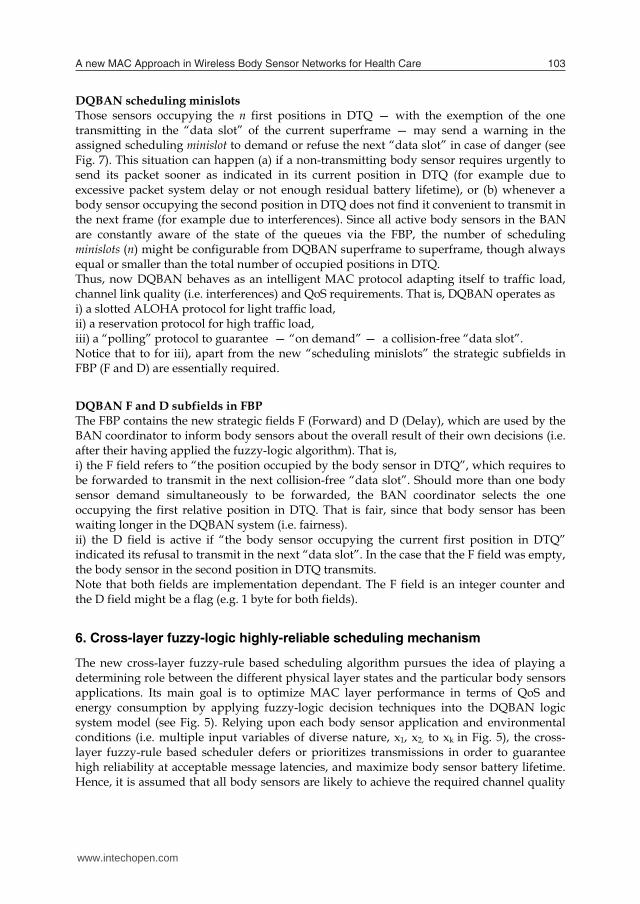
DQBAN scheduling minislots Those sensors occupying the n first positions in DTQ — with the exemption of the one transmitting in the “data slot” of the current superframe — may send a warning in the assigned scheduling minislot to demand or refuse the next “data slot” in case of danger (see Fig. 7). This situation can happen (a) if a non-transmitting body sensor requires urgently to send its packet sooner as indicated in its current position in DTQ (for example due to excessive packet system delay or not enough residual battery lifetime), or (b) whenever a body sensor occupying the second position in DTQ does not find it convenient to transmit in the next frame (for example due to interferences). Since all active body sensors in the BAN are constantly aware of the state of the queues via the FBP, the number of scheduling minislots (n) might be configurable from DQBAN superframe to superframe, though always equal or smaller than the total number of occupied positions in DTQ. Thus, now DQBAN behaves as an intelligent MAC protocol adapting itself to traffic load, channel link quality (i.e. interferences) and QoS requirements. That is, DQBAN operates as i) a slotted ALOHA protocol for light traffic load, ii) a reservation protocol for high traffic load, iii) a “polling” protocol to guarantee — “on demand” — a collision-free “data slot”. Notice that to for iii), apart from the new “scheduling minislots” the strategic subfields in FBP (F and D) are essentially required.
DQBAN F and D subfields in FBP The FBP contains the new strategic fields F (Forward) and D (Delay), which are used by the BAN coordinator to inform body sensors about the overall result of their own decisions (i.e. after their having applied the fuzzy-logic algorithm). That is, i) the F field refers to “the position occupied by the body sensor in DTQ”, which requires to be forwarded to transmit in the next collision-free “data slot”. Should more than one body sensor demand simultaneously to be forwarded, the BAN coordinator selects the one occupying the first relative position in DTQ. That is fair, since that body sensor has been waiting longer in the DQBAN system (i.e. fairness). ii) the D field is active if “the body sensor occupying the current first position in DTQ” indicated its refusal to transmit in the next “data slot”. In the case that the F field was empty, the body sensor in the second position in DTQ transmits. Note that both fields are implementation dependant. The F field is an integer counter and the D field might be a flag (e.g. 1 byte for both fields).
6. Cross-layer fuzzy-logic highly-reliable scheduling mechanism
The new cross-layer fuzzy-rule based scheduling algorithm pursues the idea of playing a determining role between the different physical layer states and the particular body sensors applications. Its main goal is to optimize MAC layer performance in terms of QoS and energy consumption by applying fuzzy-logic decision techniques into the DQBAN logic system model (see Fig. 5). Relying upon each body sensor application and environmental conditions (i.e. multiple input variables of diverse nature, x1, x2, to xk in Fig. 5), the cross-layer fuzzy-rule based scheduler defers or prioritizes transmissions in order to guarantee high reliability at acceptable message latencies, and maximize body sensor battery lifetime. Hence, it is assumed that all body sensors are likely to achieve the required channel quality
www.intechopen.com
A new MAC Approach in Wireless Body Sensor Networks for Health Care 103
ii) n “scheduling minislots” of duration scht for exceptional body sensor warnings,
iii) the collision-free “data slot” of variable duration DATAt to send body sensor packets.
Similarly, the BAN coordinator communicates to the body sensors via the fields, already described in Section 4.1 and also illustrated in Fig. 7; (a) an ACK to acknowledge the packet of the transmitting body sensor that must arrive before awt elapses, as explained in (802.15.4, 2003); (b) the synchronization PRE, which permits the energy-aware radio activation policies previously proposed; and (c) the FBP of fixed duration broadcasted by the BAN coordinator.
Fig. 7. DQBAN superframe structure Following the illustration in Fig. 7, DQBAN superframe structure ends with an inter-frame-space, as also defined in 802.15.4. Thanks to the PRE, each body sensor in the BSN uses energy-aware radio activation policies in order to maximize its battery lifetime and minimize its overall energy consumption. Thereafter, it receives all related information of the state of the queues CRQ and DTQ via the FBP. As aforementioned, the FBP is of fixed duration and includes the MCS and the packet length (Lgth) of the following data packet to be transmitted, to allow body sensors to autonomously regulate their own power management activity. Note that, apart from the PRE, the scheduling minislots and the strategic FBP subfields F (Forward) and D (Delay) are all brand-new fields especially designed to fulfill the specific BSN requirements in healthcare systems. A detailed description follows.
DQBAN scheduling minislots Those sensors occupying the n first positions in DTQ — with the exemption of the one transmitting in the “data slot” of the current superframe — may send a warning in the assigned scheduling minislot to demand or refuse the next “data slot” in case of danger (see Fig. 7). This situation can happen (a) if a non-transmitting body sensor requires urgently to send its packet sooner as indicated in its current position in DTQ (for example due to excessive packet system delay or not enough residual battery lifetime), or (b) whenever a body sensor occupying the second position in DTQ does not find it convenient to transmit in the next frame (for example due to interferences). Since all active body sensors in the BAN are constantly aware of the state of the queues via the FBP, the number of scheduling minislots (n) might be configurable from DQBAN superframe to superframe, though always equal or smaller than the total number of occupied positions in DTQ. Thus, now DQBAN behaves as an intelligent MAC protocol adapting itself to traffic load, channel link quality (i.e. interferences) and QoS requirements. That is, DQBAN operates as i) a slotted ALOHA protocol for light traffic load, ii) a reservation protocol for high traffic load, iii) a “polling” protocol to guarantee — “on demand” — a collision-free “data slot”. Notice that to for iii), apart from the new “scheduling minislots” the strategic subfields in FBP (F and D) are essentially required.
DQBAN F and D subfields in FBP The FBP contains the new strategic fields F (Forward) and D (Delay), which are used by the BAN coordinator to inform body sensors about the overall result of their own decisions (i.e. after their having applied the fuzzy-logic algorithm). That is, i) the F field refers to “the position occupied by the body sensor in DTQ”, which requires to be forwarded to transmit in the next collision-free “data slot”. Should more than one body sensor demand simultaneously to be forwarded, the BAN coordinator selects the one occupying the first relative position in DTQ. That is fair, since that body sensor has been waiting longer in the DQBAN system (i.e. fairness). ii) the D field is active if “the body sensor occupying the current first position in DTQ” indicated its refusal to transmit in the next “data slot”. In the case that the F field was empty, the body sensor in the second position in DTQ transmits. Note that both fields are implementation dependant. The F field is an integer counter and the D field might be a flag (e.g. 1 byte for both fields).
6. Cross-layer fuzzy-logic highly-reliable scheduling mechanism
The new cross-layer fuzzy-rule based scheduling algorithm pursues the idea of playing a determining role between the different physical layer states and the particular body sensors applications. Its main goal is to optimize MAC layer performance in terms of QoS and energy consumption by applying fuzzy-logic decision techniques into the DQBAN logic system model (see Fig. 5). Relying upon each body sensor application and environmental conditions (i.e. multiple input variables of diverse nature, x1, x2, to xk in Fig. 5), the cross-layer fuzzy-rule based scheduler defers or prioritizes transmissions in order to guarantee high reliability at acceptable message latencies, and maximize body sensor battery lifetime. Hence, it is assumed that all body sensors are likely to achieve the required channel quality
www.intechopen.com

Emerging Communications for Wireless Sensor Networks104
at a certain time, given the time-varying nature of the wireless link. Nevertheless, a body sensor that might have been waiting for too long in the system or suffer from critical residual battery lifetime will be prioritized so that its data is not compromised. Our scheduling algorithm employs three input continuous variables derived from each body sensor setting and the interaction with its changeable environmental conditions (i.e. wireless channel, system load) in order to decide the new order in DTQ. Bearing in mind the continuous, but dynamic and unpredictable constraints of our system, we found appropriate the use of fuzzy-logic theory for the scheduling algorithm implementation. The advantage of a fuzzy-logic approach is its simplicity of implementation and scalability when dealing with non-linear systems with multiple inputs of diverse nature (Srinoi et al., 2006).
6.1 Fuzzy-logic overview Fuzzy logic was introduced by Lofti Zadeh (1965), who claimed that many sets in the world that surrounds us are defined by a non-distinct boundary. Zadeh decided to extend two-valued logic, defined by the binary pair {0,1} to the whole continuous interval [0,1] thereby introducing a gradual transition from falsehood to truth. Fuzzy logic is a control and decision system approach that mimics human control logic, in the same way a human would make decisions. Fuzzy logic provides a simple way to arrive at a definite conclusion based upon vague, ambiguous or imprecise input information. Fuzzy-logic theory has been mainly applied to industrial problems including production systems. There has been significant attention given to modeling scheduling problems within a fuzzy framework. Several fuzzy logic based scheduling systems have been developed, although direct comparisons between them are difficult due to their different implementations and objectives (Srinoi et al., 2006). In general, a Fuzzy Logic System (FLS) is a nonlinear mapping of an input data vector into a scalar output. Fuzzy set theory establishes the specifics of the nonlinear mapping (Mendel, 1995). Fig. 8 depicts a FLS that is widely used in fuzzy logic controllers. A FLS maps crisp inputs into crisp outputs, and this mapping can be expressed quantitatively as y = f(x). It contains four components: fuzzifier, fuzzzy rules, inference engine, and defuzzifier.
x Uu U v V
( )y f x V
Fig. 8. Fuzzy logic system (FLS)
6.2 Fuzzy-logic scheduling algorithm In our current implementation design, the fuzzy-logic system integrated in each body sensor employs three cross-layer specific sensor-dependant (i) time-variant (ti) input variables to satisfy the above-mentioned requirements. These are; (a) the Signal-to-Noise Ratio in dB —
( )i iSNR t — derived at the reception of the FBP (see Fig. 7), assuming symmetry within uplink and downlink — to and from the BAN coordinator —given a certain coherence time; (b) the Waiting Time in the system in seconds — ( )i iWT t — calculated from an inherent clock; and, (c) the residual Battery Life in mAh — ( )i iBL t — derived from an inner hardware indicator. In general, a fuzzy-logic system is a nonlinear mapping of an input data vector into a scalar output and is widely used in fuzzy-logic controllers (Mendel, 1995). Fuzzy set theory establishes the specifics of the nonlinear mapping. A fuzzy logic controller contains four components: fuzzifier, fuzzzy rules, fuzzy inference process, and defuzzifier. The fuzzifier turns the input real values (also called crisp values) into linguistic variables. The fuzzzy rules are the linguistic rules, which make up the fuzzy logic controller decision behavior. The fuzzy inference process matches the linguistic input variables with the linguistic rules. The result of the fuzzy inference process is that the linguistic values are assigned to a set of linguistic output variables. Note that in our fuzzy-logic system implementation, the use of the defuzzifier is not required, since body sensors make use of a unique output linguistic variable (Decision), whose linguistic values remain invariable independently of the number of input real variables. Fuzzifier To facilitate the implementation design at the entrance of the fuzzy-logic system, we use normalized values with respect to each body sensor specific constraints: min
iSNR , derived
from its particular Bit-Error-Rate ( iBER ); maxiWT and min
iBL , application-related maximal message latency and body sensor minimal battery lifetime to send a packet of a specified length. Thus, at the entrance of the fuzzifier, there are the following normalized input crisp variables: (a) * min( ) ( )i i i i iSNR t SNR t SNR [dB]; (b) * max( ) ( )i i i i iWT t WT t WT [s]; and (c)
* min( ) ( )i i i i iBL t BL t BL [mAh]. These input normalized crisp variables in the fuzzifier are associated to the fuzzy sets with the following linguistic terms:
SNR , , ;
WT , , ;
BL , , .
dangerous poor superior
acceptable boundary excessive
critical balanced substancial
(4)
The input linguistic values {dangerous, poor, superior} constitute the antecedents of the linguistic rules for the associated input fuzzy variable SNR. The set of linguistic values {acceptable, boundary, excessive} and {critical, balanced, substantial} are associated to the input fuzzy variables WT and BL, respectively. Fig. 9 portrays an illustrative example of the membership functions used in our fuzzy-logic system for all the same sort of antecedents and consequents. The representation of linguistic2 is an isosceles triangle and the corresponding 1 2 3X , X , X figures are implementation dependant for each input fuzzy
variable and adjusted as a function of the known values miniSNR , max
iWT and miniBL . We
www.intechopen.com
A new MAC Approach in Wireless Body Sensor Networks for Health Care 105
at a certain time, given the time-varying nature of the wireless link. Nevertheless, a body sensor that might have been waiting for too long in the system or suffer from critical residual battery lifetime will be prioritized so that its data is not compromised. Our scheduling algorithm employs three input continuous variables derived from each body sensor setting and the interaction with its changeable environmental conditions (i.e. wireless channel, system load) in order to decide the new order in DTQ. Bearing in mind the continuous, but dynamic and unpredictable constraints of our system, we found appropriate the use of fuzzy-logic theory for the scheduling algorithm implementation. The advantage of a fuzzy-logic approach is its simplicity of implementation and scalability when dealing with non-linear systems with multiple inputs of diverse nature (Srinoi et al., 2006).
6.1 Fuzzy-logic overview Fuzzy logic was introduced by Lofti Zadeh (1965), who claimed that many sets in the world that surrounds us are defined by a non-distinct boundary. Zadeh decided to extend two-valued logic, defined by the binary pair {0,1} to the whole continuous interval [0,1] thereby introducing a gradual transition from falsehood to truth. Fuzzy logic is a control and decision system approach that mimics human control logic, in the same way a human would make decisions. Fuzzy logic provides a simple way to arrive at a definite conclusion based upon vague, ambiguous or imprecise input information. Fuzzy-logic theory has been mainly applied to industrial problems including production systems. There has been significant attention given to modeling scheduling problems within a fuzzy framework. Several fuzzy logic based scheduling systems have been developed, although direct comparisons between them are difficult due to their different implementations and objectives (Srinoi et al., 2006). In general, a Fuzzy Logic System (FLS) is a nonlinear mapping of an input data vector into a scalar output. Fuzzy set theory establishes the specifics of the nonlinear mapping (Mendel, 1995). Fig. 8 depicts a FLS that is widely used in fuzzy logic controllers. A FLS maps crisp inputs into crisp outputs, and this mapping can be expressed quantitatively as y = f(x). It contains four components: fuzzifier, fuzzzy rules, inference engine, and defuzzifier.
x Uu U v V
( )y f x V
Fig. 8. Fuzzy logic system (FLS)
6.2 Fuzzy-logic scheduling algorithm In our current implementation design, the fuzzy-logic system integrated in each body sensor employs three cross-layer specific sensor-dependant (i) time-variant (ti) input variables to satisfy the above-mentioned requirements. These are; (a) the Signal-to-Noise Ratio in dB —
( )i iSNR t — derived at the reception of the FBP (see Fig. 7), assuming symmetry within uplink and downlink — to and from the BAN coordinator —given a certain coherence time; (b) the Waiting Time in the system in seconds — ( )i iWT t — calculated from an inherent clock; and, (c) the residual Battery Life in mAh — ( )i iBL t — derived from an inner hardware indicator. In general, a fuzzy-logic system is a nonlinear mapping of an input data vector into a scalar output and is widely used in fuzzy-logic controllers (Mendel, 1995). Fuzzy set theory establishes the specifics of the nonlinear mapping. A fuzzy logic controller contains four components: fuzzifier, fuzzzy rules, fuzzy inference process, and defuzzifier. The fuzzifier turns the input real values (also called crisp values) into linguistic variables. The fuzzzy rules are the linguistic rules, which make up the fuzzy logic controller decision behavior. The fuzzy inference process matches the linguistic input variables with the linguistic rules. The result of the fuzzy inference process is that the linguistic values are assigned to a set of linguistic output variables. Note that in our fuzzy-logic system implementation, the use of the defuzzifier is not required, since body sensors make use of a unique output linguistic variable (Decision), whose linguistic values remain invariable independently of the number of input real variables. Fuzzifier To facilitate the implementation design at the entrance of the fuzzy-logic system, we use normalized values with respect to each body sensor specific constraints: min
iSNR , derived
from its particular Bit-Error-Rate ( iBER ); maxiWT and min
iBL , application-related maximal message latency and body sensor minimal battery lifetime to send a packet of a specified length. Thus, at the entrance of the fuzzifier, there are the following normalized input crisp variables: (a) * min( ) ( )i i i i iSNR t SNR t SNR [dB]; (b) * max( ) ( )i i i i iWT t WT t WT [s]; and (c)
* min( ) ( )i i i i iBL t BL t BL [mAh]. These input normalized crisp variables in the fuzzifier are associated to the fuzzy sets with the following linguistic terms:
SNR , , ;
WT , , ;
BL , , .
dangerous poor superior
acceptable boundary excessive
critical balanced substancial
(4)
The input linguistic values {dangerous, poor, superior} constitute the antecedents of the linguistic rules for the associated input fuzzy variable SNR. The set of linguistic values {acceptable, boundary, excessive} and {critical, balanced, substantial} are associated to the input fuzzy variables WT and BL, respectively. Fig. 9 portrays an illustrative example of the membership functions used in our fuzzy-logic system for all the same sort of antecedents and consequents. The representation of linguistic2 is an isosceles triangle and the corresponding 1 2 3X , X , X figures are implementation dependant for each input fuzzy
variable and adjusted as a function of the known values miniSNR , max
iWT and miniBL . We
www.intechopen.com
Emerging Communications for Wireless Sensor Networks106
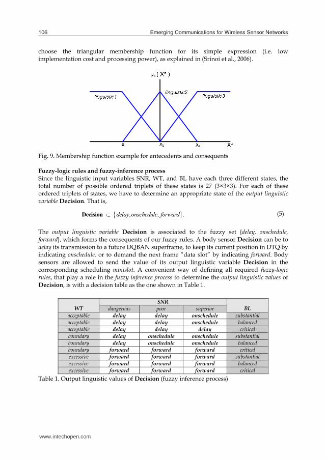
choose the triangular membership function for its simple expression (i.e. low implementation cost and processing power), as explained in (Srinoi et al., 2006).
Fig. 9. Membership function example for antecedents and consequents Fuzzy-logic rules and fuzzy-inference process Since the linguistic input variables SNR, WT, and BL have each three different states, the total number of possible ordered triplets of these states is 27 (3×3×3). For each of these ordered triplets of states, we have to determine an appropriate state of the output linguistic variable Decision. That is, , , .delay onschedule forwardDecision (5)
The output linguistic variable Decision is associated to the fuzzy set {delay, onschedule, forward}, which forms the consequents of our fuzzy rules. A body sensor Decision can be to delay its transmission to a future DQBAN superframe, to keep its current position in DTQ by indicating onschedule, or to demand the next frame “data slot” by indicating forward. Body sensors are allowed to send the value of its output linguistic variable Decision in the corresponding scheduling minislot. A convenient way of defining all required fuzzy-logic rules, that play a role in the fuzzy inference process to determine the output linguistic values of Decision, is with a decision table as the one shown in Table 1.
Table 1. Output linguistic values of Decision (fuzzy inference process)
WT
SNR BL dangerous poor superior
acceptable delay delay onschedule substantial acceptable delay delay onschedule balanced acceptable delay delay delay critical boundary delay onschedule onschedule substantial boundary delay onschedule onschedule balanced boundary forward forward forward critical excessive forward forward forward substantial excessive forward forward forward balanced excessive forward forward forward critical
Next, we provide seven high level fuzzy-logic rules for the output linguistic variable (Decision) with their antecedents and consequent as a result of the combination of the states in Table 1. The first three rules indicate when data transmission requires to be delayed. i
(1)R is used to
detect a bad link channel before transmitting. If there is still enough time and battery lifetime left, the aim is to defer data transmission; otherwise it may not be possible to guarantee a particular
iBER for the lowest power transmission state. i(2)R claims to wait
until batteries have been replaced, so that enough battery lifetime can be guaranteed during a packet transmission interval. In the same line, i
(3)R delays a transmission waiting for a
better channel quality link following Table 1 solution.
i
i
i
(1)
(2)
(3)
R : IF SNR is and WT is not and
BL is not THEN is .R : IF BL is and WT is THEN is .
R : IF SNR is not
dangerous excessivecritical delaycritical acceptable delay
sup
DecisionDecision
and WT is
THEN is .
erior acceptable
delayDecision
(6)
Both i
(4)R and i(5)R show when a body sensor can remain in the same position in DTQ since
its situation is not critical.
i
i
(4)
(5)
R : IF SNR is and WT is and
BL is not THEN is .R : IF SNR is not and WT is and
BL is not THEN
superior acceptable
critical onscheduledangerous boundary
critical
Decision
Decision is .onschedule
(7)
On the contrary, the last two rules warn body sensors about a critical situation to demand the next possible collision-free “data slot” to guarantee QoS. i
(6)R is used when a packet
system waiting time is too close to its maximum latency. Note that if SNR were dangerous, a body sensor in that situation could even increase its power transmission to compensate the bad quality link, assuming the implementation design allows that. i
(7)R warns each body
sensor about its critical residual battery life. The idea is to let the sensor send its packet in the next frame before batteries are replaced due to time constraints.
i
i
(6)
(7)
R : IF WT is THEN is .
R : IF BL is and WT is not
THEN is .
excessive forward
critical acceptable
forward
Decision
Decision
(8)
www.intechopen.com

A new MAC Approach in Wireless Body Sensor Networks for Health Care 107
choose the triangular membership function for its simple expression (i.e. low implementation cost and processing power), as explained in (Srinoi et al., 2006).
Fig. 9. Membership function example for antecedents and consequents Fuzzy-logic rules and fuzzy-inference process Since the linguistic input variables SNR, WT, and BL have each three different states, the total number of possible ordered triplets of these states is 27 (3×3×3). For each of these ordered triplets of states, we have to determine an appropriate state of the output linguistic variable Decision. That is, , , .delay onschedule forwardDecision (5)
The output linguistic variable Decision is associated to the fuzzy set {delay, onschedule, forward}, which forms the consequents of our fuzzy rules. A body sensor Decision can be to delay its transmission to a future DQBAN superframe, to keep its current position in DTQ by indicating onschedule, or to demand the next frame “data slot” by indicating forward. Body sensors are allowed to send the value of its output linguistic variable Decision in the corresponding scheduling minislot. A convenient way of defining all required fuzzy-logic rules, that play a role in the fuzzy inference process to determine the output linguistic values of Decision, is with a decision table as the one shown in Table 1.
Table 1. Output linguistic values of Decision (fuzzy inference process)
WT
SNR BL dangerous poor superior
acceptable delay delay onschedule substantial acceptable delay delay onschedule balanced acceptable delay delay delay critical boundary delay onschedule onschedule substantial boundary delay onschedule onschedule balanced boundary forward forward forward critical excessive forward forward forward substantial excessive forward forward forward balanced excessive forward forward forward critical
Next, we provide seven high level fuzzy-logic rules for the output linguistic variable (Decision) with their antecedents and consequent as a result of the combination of the states in Table 1. The first three rules indicate when data transmission requires to be delayed. i
(1)R is used to
detect a bad link channel before transmitting. If there is still enough time and battery lifetime left, the aim is to defer data transmission; otherwise it may not be possible to guarantee a particular
iBER for the lowest power transmission state. i(2)R claims to wait
until batteries have been replaced, so that enough battery lifetime can be guaranteed during a packet transmission interval. In the same line, i
(3)R delays a transmission waiting for a
better channel quality link following Table 1 solution.
i
i
i
(1)
(2)
(3)
R : IF SNR is and WT is not and
BL is not THEN is .R : IF BL is and WT is THEN is .
R : IF SNR is not
dangerous excessivecritical delaycritical acceptable delay
sup
DecisionDecision
and WT is
THEN is .
erior acceptable
delayDecision
(6)
Both i
(4)R and i(5)R show when a body sensor can remain in the same position in DTQ since
its situation is not critical.
i
i
(4)
(5)
R : IF SNR is and WT is and
BL is not THEN is .R : IF SNR is not and WT is and
BL is not THEN
superior acceptable
critical onscheduledangerous boundary
critical
Decision
Decision is .onschedule
(7)
On the contrary, the last two rules warn body sensors about a critical situation to demand the next possible collision-free “data slot” to guarantee QoS. i
(6)R is used when a packet
system waiting time is too close to its maximum latency. Note that if SNR were dangerous, a body sensor in that situation could even increase its power transmission to compensate the bad quality link, assuming the implementation design allows that. i
(7)R warns each body
sensor about its critical residual battery life. The idea is to let the sensor send its packet in the next frame before batteries are replaced due to time constraints.
i
i
(6)
(7)
R : IF WT is THEN is .
R : IF BL is and WT is not
THEN is .
excessive forward
critical acceptable
forward
Decision
Decision
(8)
www.intechopen.com
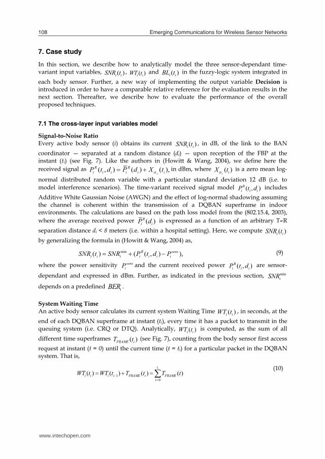
Emerging Communications for Wireless Sensor Networks108
7. Case study
In this section, we describe how to analytically model the three sensor-dependant time-variant input variables, ( )i iSNR t , ( )i iWT t and ( )i iBL t in the fuzzy-logic system integrated in each body sensor. Further, a new way of implementing the output variable Decision is introduced in order to have a comparable relative reference for the evaluation results in the next section. Thereafter, we describe how to evaluate the performance of the overall proposed techniques.
7.1 The cross-layer input variables model Signal-to-Noise Ratio Every active body sensor (i) obtains its current ( )i iSNR t , in dB, of the link to the BAN coordinator — separated at a random distance (di) — upon reception of the FBP at the instant (ti) (see Fig. 7). Like the authors in (Howitt & Wang, 2004), we define here the received signal as ( , ) ( ) ( ),
s
R Ri i i i i iP t d P d X t in dBm, where ( )
s iX t is a zero mean log-
normal distributed random variable with a particular standard deviation 12 dB (i.e. to model interference scenarios). The time-variant received signal model ( , )R
i i iP t d includes Additive White Gaussian Noise (AWGN) and the effect of log-normal shadowing assuming the channel is coherent within the transmission of a DQBAN superframe in indoor environments. The calculations are based on the path loss model from the (802.15.4, 2003), where the average received power ( )R
i iP d is expressed as a function of an arbitrary T–R separation distance di < 8 meters (i.e. within a hospital setting). Here, we compute ( )i iSNR t by generalizing the formula in (Howitt & Wang, 2004) as,
min( ) ( ( , ) ),R sensi i i i i i iSNR t SNR P t d P (9)
where the power sensitivity sensiP and the current received power ( , )R
i i iP t d are sensor-
dependant and expressed in dBm. Further, as indicated in the previous section, miniSNR
depends on a predefined iBER . System Waiting Time An active body sensor calculates its current system Waiting Time ( )i iWT t , in seconds, at the end of each DQBAN superframe at instant (ti), every time it has a packet to transmit in the queuing system (i.e. CRQ or DTQ). Analytically, ( )i iWT t is computed, as the sum of all different time superframes ( )FRAME iT t (see Fig. 7), counting from the body sensor first access request at instant (t = 0) until the current time (t = ti) for a particular packet in the DQBAN system. That is,
10
( ) ( ) ( ) ( )it
i i i i FRAME i FRAMEt
WT t WT t T t T t (10)
where ( )FRAME ARS sch DATA aw PRE FBP IFST m t n t t t t t t t . Please refer to Section 4.1 for the specific time definitions and bear in mind that the number of scheduling minislots ( )n tmight be configurable from DQBAN superframe to DQBAN superframe. Residual Battery Life Body sensor residual Battery Lifetime ( )i iBL t , in mAh, is obtained as the difference from its initial charged battery ini
iB at the time the sensor sends its first access request (t = 0) and the consumed battery cons
iB at the end of each time frame (t = ti) for a particular packet in the DQBAN queuing system. That is,
0( ) ( ) ( ( ) ( )),
itini cons ini tx rx idle
i i i i i i i i it
BL t B B t B B t B B t
(11)
where ( )consi iB t has been calculated following the power management scenario described in
Section 4 for a sensor waiting in DTQ. Further,
( ) ( ( ) ( )) ,
( ) ,
( ) ( ( ) ( ) ) ,
txi ARS sch txrxi pre FBP rx
idlei ARS sch DATA aw IFS idle
B t t t t t IB t t I
B t m t n t t T t t t I
(12)
where txI , rxI and idleI are the minimum consumption values in transmit, receive and idle modes corresponding to Chipcon specification data sheet for CC2420 transceiver (Chipcon) in mAh. Note that all other time values have been defined in Section 4.1.
7.2 Performance evaluation metrics The performance of the proposed techniques is evaluated in a star-based topology BSN where different body sensors with their specific medical requirements communicate with the BAN coordinator in a hospital care scenario through a shared wireless indoor radio channel (see Fig. 1). For scalability reasons, the proposed techniques have been assessed in two specific scenarios, i) a homogenous scenario characterized by a BSN with only wireless ECG body sensors. ii) a heterogeneous scenario characterized by a BSN with a number of ECG body sensors and other different medical sensors with their own specific QoS demands.
Table 2. Medical body sensors specifications
BODY SENSORS ECG Doctor PDA Blood Pressure
Respiratory Rate
Endoscope Imaging
BER 10-6 10-6 10-8 10-7 10-4 Latency 0.3 s 1 s 0.75 s 0.6 s 0.5 s
Traffic distribution Constant Poisson Constant Constant Poisson Message generation rate 500 byte/s 1000 byte/s 512 byte/s 1024 byte/s 1538,46 bytes/s Inter-arrival packet time 0.20 s 0.10 s 0.195 s 0.097 s 0.065 s
www.intechopen.com
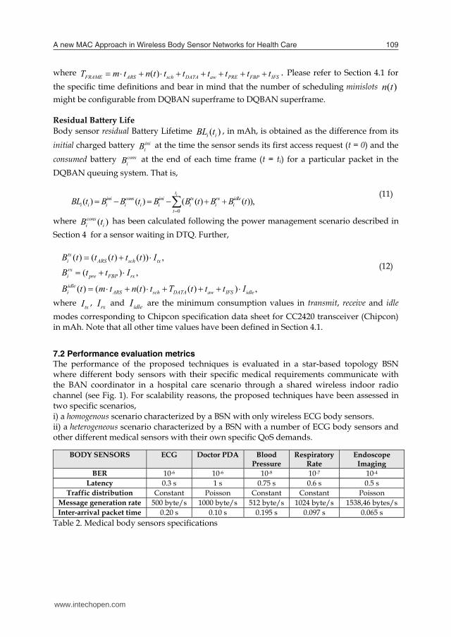
A new MAC Approach in Wireless Body Sensor Networks for Health Care 109
7. Case study
In this section, we describe how to analytically model the three sensor-dependant time-variant input variables, ( )i iSNR t , ( )i iWT t and ( )i iBL t in the fuzzy-logic system integrated in each body sensor. Further, a new way of implementing the output variable Decision is introduced in order to have a comparable relative reference for the evaluation results in the next section. Thereafter, we describe how to evaluate the performance of the overall proposed techniques.
7.1 The cross-layer input variables model Signal-to-Noise Ratio Every active body sensor (i) obtains its current ( )i iSNR t , in dB, of the link to the BAN coordinator — separated at a random distance (di) — upon reception of the FBP at the instant (ti) (see Fig. 7). Like the authors in (Howitt & Wang, 2004), we define here the received signal as ( , ) ( ) ( ),
s
R Ri i i i i iP t d P d X t in dBm, where ( )
s iX t is a zero mean log-
normal distributed random variable with a particular standard deviation 12 dB (i.e. to model interference scenarios). The time-variant received signal model ( , )R
i i iP t d includes Additive White Gaussian Noise (AWGN) and the effect of log-normal shadowing assuming the channel is coherent within the transmission of a DQBAN superframe in indoor environments. The calculations are based on the path loss model from the (802.15.4, 2003), where the average received power ( )R
i iP d is expressed as a function of an arbitrary T–R separation distance di < 8 meters (i.e. within a hospital setting). Here, we compute ( )i iSNR t by generalizing the formula in (Howitt & Wang, 2004) as,
min( ) ( ( , ) ),R sensi i i i i i iSNR t SNR P t d P (9)
where the power sensitivity sensiP and the current received power ( , )R
i i iP t d are sensor-
dependant and expressed in dBm. Further, as indicated in the previous section, miniSNR
depends on a predefined iBER . System Waiting Time An active body sensor calculates its current system Waiting Time ( )i iWT t , in seconds, at the end of each DQBAN superframe at instant (ti), every time it has a packet to transmit in the queuing system (i.e. CRQ or DTQ). Analytically, ( )i iWT t is computed, as the sum of all different time superframes ( )FRAME iT t (see Fig. 7), counting from the body sensor first access request at instant (t = 0) until the current time (t = ti) for a particular packet in the DQBAN system. That is,
10
( ) ( ) ( ) ( )it
i i i i FRAME i FRAMEt
WT t WT t T t T t (10)
where ( )FRAME ARS sch DATA aw PRE FBP IFST m t n t t t t t t t . Please refer to Section 4.1 for the specific time definitions and bear in mind that the number of scheduling minislots ( )n tmight be configurable from DQBAN superframe to DQBAN superframe. Residual Battery Life Body sensor residual Battery Lifetime ( )i iBL t , in mAh, is obtained as the difference from its initial charged battery ini
iB at the time the sensor sends its first access request (t = 0) and the consumed battery cons
iB at the end of each time frame (t = ti) for a particular packet in the DQBAN queuing system. That is,
0( ) ( ) ( ( ) ( )),
itini cons ini tx rx idle
i i i i i i i i it
BL t B B t B B t B B t
(11)
where ( )consi iB t has been calculated following the power management scenario described in
Section 4 for a sensor waiting in DTQ. Further,
( ) ( ( ) ( )) ,
( ) ,
( ) ( ( ) ( ) ) ,
txi ARS sch txrxi pre FBP rx
idlei ARS sch DATA aw IFS idle
B t t t t t IB t t I
B t m t n t t T t t t I
(12)
where txI , rxI and idleI are the minimum consumption values in transmit, receive and idle modes corresponding to Chipcon specification data sheet for CC2420 transceiver (Chipcon) in mAh. Note that all other time values have been defined in Section 4.1.
7.2 Performance evaluation metrics The performance of the proposed techniques is evaluated in a star-based topology BSN where different body sensors with their specific medical requirements communicate with the BAN coordinator in a hospital care scenario through a shared wireless indoor radio channel (see Fig. 1). For scalability reasons, the proposed techniques have been assessed in two specific scenarios, i) a homogenous scenario characterized by a BSN with only wireless ECG body sensors. ii) a heterogeneous scenario characterized by a BSN with a number of ECG body sensors and other different medical sensors with their own specific QoS demands.
Table 2. Medical body sensors specifications
BODY SENSORS ECG Doctor PDA Blood Pressure
Respiratory Rate
Endoscope Imaging
BER 10-6 10-6 10-8 10-7 10-4 Latency 0.3 s 1 s 0.75 s 0.6 s 0.5 s
Traffic distribution Constant Poisson Constant Constant Poisson Message generation rate 500 byte/s 1000 byte/s 512 byte/s 1024 byte/s 1538,46 bytes/s Inter-arrival packet time 0.20 s 0.10 s 0.195 s 0.097 s 0.065 s
www.intechopen.com
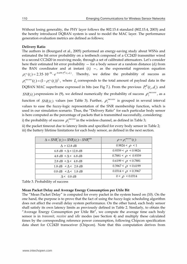
Emerging Communications for Wireless Sensor Networks110
Without losing generality, the PHY layer follows the 802.15.4 standard (802.15.4, 2003) and the hereby introduced DQBAN system is used to model the MAC layer. The performance generation evaluation metrics are defined as follows; Delivery Ratio The authors in (Bourgard et al., 2005) performed an energy-saving study about WSNs and estimated the bit error probability on a testbench composed of a CC2420 transmitter wired to a second CC2420 in receiving mode, through a set of calibrated attenuators. Let’s consider here their estimated bit error probability — for a body sensor at a random distance (di) from the BAN coordinator and at instant (ti) —, as the exponential regression equation
0.659 ( , )30( ) 2.35 10R
bit i i iP t di it e . Thereby, we define the probability of success as
( ) (1 ( )) ,bit iLsuccessi i i it t where iL corresponds to the total amount of payload data in the
DQBAN MAC superframe expressed in bits (see Fig 7.). From the previous ( , )Ri i iP t d and
( )i iSNR t expressions in (9), we defined numerically the probability of success successi , as a
function of ( )i iSNR t values (see Table 3). Further, successi is grouped in several interval
values to ease the fuzzy-logic representation of the SNR membership function, which is used in our simulation scenario. Thus, the “Delivery Ratio” for each particular body sensor is here computed as the percentage of packets that is transmitted successfully, considering: i) the probability of success success
i in the wireless channel, as defined in Table 3; ii) the packet timeout due to latency limits and specified for every body sensor in Table 2; iii) the battery lifetime limitations for each body sensor, as defined in the next section.
* min( ) ( )i i i i iSNR t SNR t SNR ( )successi it
> 12.8 dB 0.9824 < < 1
6.8 dB << 12.8 dB 0.9359 < < 0.9824
4.8 dB << 6.8 dB 0.7881 < < 0.9359
2.8 dB << 4.8 dB 0.6199 < < 0.7881
1.8 dB << 2.8 dB 0.3967 < < 0.6199
0.8 dB << 1.8 dB 0.0314 < < 0.3967
< 0.8 dB 0 < < 0.0314
Table 3. Probability of success Mean Packet Delay and Average Energy Consumption per Utile Bit The “Mean Packet Delay” is computed for every packet in the system based on (10). On the one hand, the purpose is to prove that the fact of using the fuzzy-logic scheduling algorithm does not affect the overall delay system performance. On the other hand, each body sensor shall satisfy its own latency limits as previously defined in Table 2. Similarly, to obtain the “Average Energy Consumption per Utile Bit”, we compute the average time each body sensor is in transmit, receive and idle modes (see Section 4) and multiply these calculated times by the corresponding reference power consumption, following Chipcon specification data sheet for CC2420 transceiver (Chipcon). Note that this computation derives from
formulas (11) and (12). To eventually attain the energy consumption per utile bit, we divide per the total average number of information (utile) bits per frame.
8. DQBAN performance evaluation results
By means of MATLAB computer simulations, we evaluate the aforementioned metrics — “Delivery Ratio”, “Mean Packet Delay” and “Average Energy Consumption per Utile Bit” —, to assess the scalability of the DQBAN system performance as the number of body sensors — in a star-based BSN with a single BAN coordinator — increases until saturation conditions, i) from 5 to 35 in a homogenous scenario with 1-lead ECG body sensors with different initial amount of battery; and, ii) from 10 to 35 in a heterogeneous scenario characterized by 4 different medical sensors as defined in Table 2 (i.e. Clinical PDA, Blood Pressure, Respiratory Rate, Endoscope Imaging) and a growing number of 1-lead ECG sensors. Be aware that all body sensors are randomly placed at 1-meter to 8-meter distance away from the BAN coordinator in order to symbolize different channel link qualities, as previously detailed in Section 7. In order to define the particular characteristics of the medical sensors, we have considered a similar approach as authors in (Golmie et al., 2005); (Chevrollier & Golmie, 2005). Medical sensors specifications in Table 2 typify each body sensor requirements in terms of BER, latency, traffic generation distribution and message generation rate or inter-arrival packet time at 250 Kb/s as in 802.15.4 (802.15.4, 2003). The selected medical sensors are just a mere example of possible applications in hospital settings. For the sake of simplicity, all body sensors in the heterogeneous scenario are initially charged with the same amount of battery, i.e. 5500 mAh in our simulations. Whenever a body sensor runs out of battery, its replacement is supposed to be automatically, since the number of body sensors just increases from iteration to iteration and, it never decreases.
8.1 System parameters Following DQBAN superframe structure (see Fig 7.), the chosen reference scenario is defined by the set of system parameters provided in Table 4, whose fields correspond to 802.15.4 MAC default values in the upper frequency band at 2.4 GHz and at the unique standardized data rate 250 Kb/s (802.15.4, 2003).
Table 4. DQBAN parameters based on 802.15.4 MAC values We use one of the longest possible data packet payload lengths — 100 bytes — in order to minimize PHY and MAC overhead per utile (information) bit. Observe that DQBAN preamble and FBP lengths have been based on the 802.15.4 PHY preamble and MAC beacon frame, respectively. For each of the four FBP subfields shown in Fig. 7 though, just 1 byte is required (i.e. 4 bytes). Here the DQBAN m access minislots occupy each the equivalent of 1 byte. That is a conservative estimate, since theoretically a single bit could do the job, and
PHY header 6 bytes ACK 11 bytes MAC header 9 bytes Preamble 4 bytes Data Payload 100 bytes FBP 11 bytes Taw 864 μs TIFS 192 μs
www.intechopen.com

A new MAC Approach in Wireless Body Sensor Networks for Health Care 111
Without losing generality, the PHY layer follows the 802.15.4 standard (802.15.4, 2003) and the hereby introduced DQBAN system is used to model the MAC layer. The performance generation evaluation metrics are defined as follows; Delivery Ratio The authors in (Bourgard et al., 2005) performed an energy-saving study about WSNs and estimated the bit error probability on a testbench composed of a CC2420 transmitter wired to a second CC2420 in receiving mode, through a set of calibrated attenuators. Let’s consider here their estimated bit error probability — for a body sensor at a random distance (di) from the BAN coordinator and at instant (ti) —, as the exponential regression equation
0.659 ( , )30( ) 2.35 10R
bit i i iP t di it e . Thereby, we define the probability of success as
( ) (1 ( )) ,bit iLsuccessi i i it t where iL corresponds to the total amount of payload data in the
DQBAN MAC superframe expressed in bits (see Fig 7.). From the previous ( , )Ri i iP t d and
( )i iSNR t expressions in (9), we defined numerically the probability of success successi , as a
function of ( )i iSNR t values (see Table 3). Further, successi is grouped in several interval
values to ease the fuzzy-logic representation of the SNR membership function, which is used in our simulation scenario. Thus, the “Delivery Ratio” for each particular body sensor is here computed as the percentage of packets that is transmitted successfully, considering: i) the probability of success success
i in the wireless channel, as defined in Table 3; ii) the packet timeout due to latency limits and specified for every body sensor in Table 2; iii) the battery lifetime limitations for each body sensor, as defined in the next section.
* min( ) ( )i i i i iSNR t SNR t SNR ( )successi it
> 12.8 dB 0.9824 < < 1
6.8 dB << 12.8 dB 0.9359 < < 0.9824
4.8 dB << 6.8 dB 0.7881 < < 0.9359
2.8 dB << 4.8 dB 0.6199 < < 0.7881
1.8 dB << 2.8 dB 0.3967 < < 0.6199
0.8 dB << 1.8 dB 0.0314 < < 0.3967
< 0.8 dB 0 < < 0.0314
Table 3. Probability of success Mean Packet Delay and Average Energy Consumption per Utile Bit The “Mean Packet Delay” is computed for every packet in the system based on (10). On the one hand, the purpose is to prove that the fact of using the fuzzy-logic scheduling algorithm does not affect the overall delay system performance. On the other hand, each body sensor shall satisfy its own latency limits as previously defined in Table 2. Similarly, to obtain the “Average Energy Consumption per Utile Bit”, we compute the average time each body sensor is in transmit, receive and idle modes (see Section 4) and multiply these calculated times by the corresponding reference power consumption, following Chipcon specification data sheet for CC2420 transceiver (Chipcon). Note that this computation derives from
formulas (11) and (12). To eventually attain the energy consumption per utile bit, we divide per the total average number of information (utile) bits per frame.
8. DQBAN performance evaluation results
By means of MATLAB computer simulations, we evaluate the aforementioned metrics — “Delivery Ratio”, “Mean Packet Delay” and “Average Energy Consumption per Utile Bit” —, to assess the scalability of the DQBAN system performance as the number of body sensors — in a star-based BSN with a single BAN coordinator — increases until saturation conditions, i) from 5 to 35 in a homogenous scenario with 1-lead ECG body sensors with different initial amount of battery; and, ii) from 10 to 35 in a heterogeneous scenario characterized by 4 different medical sensors as defined in Table 2 (i.e. Clinical PDA, Blood Pressure, Respiratory Rate, Endoscope Imaging) and a growing number of 1-lead ECG sensors. Be aware that all body sensors are randomly placed at 1-meter to 8-meter distance away from the BAN coordinator in order to symbolize different channel link qualities, as previously detailed in Section 7. In order to define the particular characteristics of the medical sensors, we have considered a similar approach as authors in (Golmie et al., 2005); (Chevrollier & Golmie, 2005). Medical sensors specifications in Table 2 typify each body sensor requirements in terms of BER, latency, traffic generation distribution and message generation rate or inter-arrival packet time at 250 Kb/s as in 802.15.4 (802.15.4, 2003). The selected medical sensors are just a mere example of possible applications in hospital settings. For the sake of simplicity, all body sensors in the heterogeneous scenario are initially charged with the same amount of battery, i.e. 5500 mAh in our simulations. Whenever a body sensor runs out of battery, its replacement is supposed to be automatically, since the number of body sensors just increases from iteration to iteration and, it never decreases.
8.1 System parameters Following DQBAN superframe structure (see Fig 7.), the chosen reference scenario is defined by the set of system parameters provided in Table 4, whose fields correspond to 802.15.4 MAC default values in the upper frequency band at 2.4 GHz and at the unique standardized data rate 250 Kb/s (802.15.4, 2003).
Table 4. DQBAN parameters based on 802.15.4 MAC values We use one of the longest possible data packet payload lengths — 100 bytes — in order to minimize PHY and MAC overhead per utile (information) bit. Observe that DQBAN preamble and FBP lengths have been based on the 802.15.4 PHY preamble and MAC beacon frame, respectively. For each of the four FBP subfields shown in Fig. 7 though, just 1 byte is required (i.e. 4 bytes). Here the DQBAN m access minislots occupy each the equivalent of 1 byte. That is a conservative estimate, since theoretically a single bit could do the job, and
PHY header 6 bytes ACK 11 bytes MAC header 9 bytes Preamble 4 bytes Data Payload 100 bytes FBP 11 bytes Taw 864 μs TIFS 192 μs
www.intechopen.com

Emerging Communications for Wireless Sensor Networks112
practically speaking, each body sensor access request could be a separate modulated signal transmission (Xu & Campbell, 1992). Similarly, for the DQBAN novel n scheduling minislots, the same length of 1 byte is reserved to indicate either forward or delay (i.e. Decision output linguistic values). In our current DQBAN simulations, there are m = 3 access minislots (as in the original (Xu & Campbell, 1992); and n = 5 scheduling minislots, even though n could be configurable from DQBAN superframe to DQBAN superframe, depending on the number of body sensors in DTQ. To simulate the fuzzy-logic system integrated each body sensor, we utilize a MATLAB fuzz-logic toolbox. The aforementioned 1 3X , X values for each
membership function (see Fig 8) are derived by computer simulations as: (a) 1 3X , X 1.8,12.8 dB for SNR (following Table 3); (b) 1 3X ,X -0.108,0.012 seconds for
WT, and (c) 1 3X , X 1000, 2000 mAh for BL.
8.2 Simulation results For the overall evaluation of the DQBAN MAC system performance, we carried out the following models and comparisons among them in both homogenous and heterogeneous depicted hospital care scenarios, A. DQBAN model (i.e. with the fuzzy-logic system scheduler and energy-aware radio activation policies), B. DQ model with a general cost function scheduler as in (Chen et al., 2006) and energy-aware radio activation policies, C. DQ without any scheduler implementation as in Section 4 (i.e. though with the energy-aware radio activation policies), D. DQ with neither any energy-aware radio activation policy nor any scheduling algorithm implementation, that is as in (Lin & Campbell, 1993); (Xu & Campbell, 1992).
The results of the “Delivery Ratio”, “Mean Packet Delay” and “Average Energy Consumption per Utile Bit” metrics are portrayed in Fig. 9 and Fig. 10 after long iterating and achieving the permanent regime of the DQBAN scheme.
Homogenous Scenario Fig. 10 depicts the DQBAN MAC performance in a homogenous BSN with an increasing number of 1-lead ECG body sensors, whose characteristics are specified in Table 2. Note that 20% of the ECG sensors involved in each simulation are initially charged with much less amount of battery. The idea is to evaluate the energy-saving behavior of the DQBAN system as the traffic load rises until saturation conditions. The “Average Energy Consumption per Utile Bit” in graphic Fig. 10(a) illustrates the requirement of an energy-aware activation policy. In a typical DQ MAC protocol (Lin & Campbell, 1993); (Xu & Campbell, 1992), no energy-saving techniques are utilized. Therefore, as the traffic load increases in the BSN, body sensors remaining longer in the system may run out of battery. As a result, the average energy-consumption per delivered information bit increases. Fig. 10(c) emphasizes that by using energy-aware radio activation policies plus a scheduling algorithm, the MAC layer improves in terms of average energy consumption per utile bit. DQBAN outperforms the aforementioned B. and C. implementations. Notice that it was already proved in Section 4 that the energy-consumption of the DQ MAC (implementation C.) outperforms 802.15.4 in
all possible scenarios. The “Delivery Ratio” graphic Fig. 10(b) proves that the fact of scheduling data packets taking cross-layer constraints into account outperforms the first come first served discipline of the original DQ protocol by guaranteeing the QoS requirements of high reliability, right message latency and enough battery lifetime to all body sensors transmissions in the BSN (as described in Section 7.2). The use of DQBAN with the proposed cross-layer fuzzy-rule base scheduling algorithm reaches more than 95% of transmission successes, even though 20% of the ECG sensors have critical battery constraints. Close to saturation limits, DQBAN achievement is specifically 42.75% superior to the original DQ protocol without any energy-aware policy (i.e. implementation D.) and 11.78% superior compared to implementation C. The slight raise in the “Delivery Ratio”, in implementations A. and B., results from the growing number of body sensors in DTQ. That is, it is easier to find a body sensor with the appropriate environmental conditions to be scheduled in the first place, while others are reluctant to transmit. Further, Fig. 10(d) confirms that the use DQBAN is also appropriate in terms of “Mean Packet Delay” and still outperforms implementation B., as in all previous studied scenarios.
Fig. 10. “Average energy consumption per utile bit” (a) – (c), “Delivery Ratio” (b) and “Mean Packet Delay” (d) in the homogenous Scenario
www.intechopen.com

A new MAC Approach in Wireless Body Sensor Networks for Health Care 113
practically speaking, each body sensor access request could be a separate modulated signal transmission (Xu & Campbell, 1992). Similarly, for the DQBAN novel n scheduling minislots, the same length of 1 byte is reserved to indicate either forward or delay (i.e. Decision output linguistic values). In our current DQBAN simulations, there are m = 3 access minislots (as in the original (Xu & Campbell, 1992); and n = 5 scheduling minislots, even though n could be configurable from DQBAN superframe to DQBAN superframe, depending on the number of body sensors in DTQ. To simulate the fuzzy-logic system integrated each body sensor, we utilize a MATLAB fuzz-logic toolbox. The aforementioned 1 3X , X values for each
membership function (see Fig 8) are derived by computer simulations as: (a) 1 3X , X 1.8,12.8 dB for SNR (following Table 3); (b) 1 3X ,X -0.108,0.012 seconds for
WT, and (c) 1 3X , X 1000, 2000 mAh for BL.
8.2 Simulation results For the overall evaluation of the DQBAN MAC system performance, we carried out the following models and comparisons among them in both homogenous and heterogeneous depicted hospital care scenarios, A. DQBAN model (i.e. with the fuzzy-logic system scheduler and energy-aware radio activation policies), B. DQ model with a general cost function scheduler as in (Chen et al., 2006) and energy-aware radio activation policies, C. DQ without any scheduler implementation as in Section 4 (i.e. though with the energy-aware radio activation policies), D. DQ with neither any energy-aware radio activation policy nor any scheduling algorithm implementation, that is as in (Lin & Campbell, 1993); (Xu & Campbell, 1992).
The results of the “Delivery Ratio”, “Mean Packet Delay” and “Average Energy Consumption per Utile Bit” metrics are portrayed in Fig. 9 and Fig. 10 after long iterating and achieving the permanent regime of the DQBAN scheme.
Homogenous Scenario Fig. 10 depicts the DQBAN MAC performance in a homogenous BSN with an increasing number of 1-lead ECG body sensors, whose characteristics are specified in Table 2. Note that 20% of the ECG sensors involved in each simulation are initially charged with much less amount of battery. The idea is to evaluate the energy-saving behavior of the DQBAN system as the traffic load rises until saturation conditions. The “Average Energy Consumption per Utile Bit” in graphic Fig. 10(a) illustrates the requirement of an energy-aware activation policy. In a typical DQ MAC protocol (Lin & Campbell, 1993); (Xu & Campbell, 1992), no energy-saving techniques are utilized. Therefore, as the traffic load increases in the BSN, body sensors remaining longer in the system may run out of battery. As a result, the average energy-consumption per delivered information bit increases. Fig. 10(c) emphasizes that by using energy-aware radio activation policies plus a scheduling algorithm, the MAC layer improves in terms of average energy consumption per utile bit. DQBAN outperforms the aforementioned B. and C. implementations. Notice that it was already proved in Section 4 that the energy-consumption of the DQ MAC (implementation C.) outperforms 802.15.4 in
all possible scenarios. The “Delivery Ratio” graphic Fig. 10(b) proves that the fact of scheduling data packets taking cross-layer constraints into account outperforms the first come first served discipline of the original DQ protocol by guaranteeing the QoS requirements of high reliability, right message latency and enough battery lifetime to all body sensors transmissions in the BSN (as described in Section 7.2). The use of DQBAN with the proposed cross-layer fuzzy-rule base scheduling algorithm reaches more than 95% of transmission successes, even though 20% of the ECG sensors have critical battery constraints. Close to saturation limits, DQBAN achievement is specifically 42.75% superior to the original DQ protocol without any energy-aware policy (i.e. implementation D.) and 11.78% superior compared to implementation C. The slight raise in the “Delivery Ratio”, in implementations A. and B., results from the growing number of body sensors in DTQ. That is, it is easier to find a body sensor with the appropriate environmental conditions to be scheduled in the first place, while others are reluctant to transmit. Further, Fig. 10(d) confirms that the use DQBAN is also appropriate in terms of “Mean Packet Delay” and still outperforms implementation B., as in all previous studied scenarios.
Fig. 10. “Average energy consumption per utile bit” (a) – (c), “Delivery Ratio” (b) and “Mean Packet Delay” (d) in the homogenous Scenario
www.intechopen.com

Emerging Communications for Wireless Sensor Networks114
Heterogeneous Scenario Fig. 11 illustrates the DQBAN MAC performance in a hospital scenario with heterogeneous traffic. The heterogeneous BSN is characterized by four specific medical body/portable sensors defined in Table 2; a blood pressure body sensor, a respiratory rate body sensor, a real-time endoscope camera and a portable clinical PDA, while the number of ECG body sensors increases from simulated iteration to iteration, as previously explained. In order to facilitate the evaluation of the “Delivery Ratio” metric of the implementations A., B. and C., Fig. 11(a) portrays the performance of the Blood Pressure body sensor and the average performance of the total number of ECG sensors in the heterogeneous BSN, separately. When it comes to evaluate the “Delivery Ratio” of the Blood Pressure body sensor, DQBAN is specifically 3.44% and 10% higher than that of implementations B. and C., respectively. In the average ECG case, DQBAN is 3.38% and 10.83% better than B. and C., respectively, while reaching more than 96% of transmission successes. Similarly, Fig. 11(b) depicts the DQBAN achievements for the Respiratory Rate body sensor (17.10%) and the Endoscope Imaging (13.18%) with respect to implementation C. As aforementioned, the slight raise in the “Delivery Ratio”, in implementations A. and B., results from the growing number of body sensors in DTQ.
Fig. 11. DQBAN “Delivery Ratio” (a) – (b), “Average Energy Consumption per Utile Bit” (c) and “Mean Packet Delay” (d) in the heterogeneous Scenario
In saturation conditions, DQBAN reaches nearly 90% (Respiratory Rate sensor) and 95% (Endoscope Imaging) of transmission successes. Like in the previous studied homogenous scenario, Fig. 11 (c) and (d) show the “Average Energy Consumption per Utile Bit” and the “Mean Packet Delay” of all medical body sensors involved therein, confirming again the good inherent performance of the DQBAN model. In general, DQBAN outperforms the B. and C. implementations in all analyzed scenarios, while being more appropriate than B. in terms of scalability for healthcare applications.
9. Conclusions
In this chapter, a new energy-efficiency theoretical analysis for an enhanced DQ MAC protocol has been introduced, as a potential candidate for future BSNs. For that purpose, energy-aware radio activation policies are first introduced in order to allow power management regulation to minimize the energy consumption per information bit. The analytical study has been validated by simulation results, which have shown that the proposed mechanism outperforms IEEE 802.15.4 MAC energy-efficiency for all traffic loads in a generalized BSN scenario. Further, the proposed MAC protocol commitment is to also guarantee that all packet transmissions are served with their particular application-dependant QoS requirements (i.e. reliability and message latency), without endangering body sensors battery lifetime in BSNs. For that purpose, a cross-layer fuzzy-rule scheduling algorithm has been introduced. This scheduling mechanism permits a body sensor, though not occupying the first position in the new MAC queuing model, to send its packet in the next frame in order to achieve a far more reliable system performance. The new DQBAN MAC model has been evaluated in a star-based BSNs under two different realistic hospital scenarios with diverse medical body sensor characterizations. The evaluation metric results are in terms of “delivery ratio”, “average energy consumption per utile bit” and “mean packet delay”, as the traffic load in the BSN rises to saturation limits. By means of computer simulations, the DQBAN MAC model has shown to achieve higher reliabilities than other possible MAC implementations, while fulfilling body sensor specific latency demands and battery limits. Thus, the use of DQBAN MAC reaches high transmission successes even in saturation conditions, while keeping the good inherent energy-saving protocol behaviour. This proves to scale for future BSN in healthcare scenarios.
10. References
Alonso, L.; Ferrús, R. & Agustí, R. (2005). WLAN Throughput Improvement via Distributed Queuing MAC, IEEE Communication Letters, pp. 310–12, Vol. 9, No. 4, April 2005.
Bourgard, B.; Catthoor, F.; Daly, D.C.; Chandrakasam A. & Dehaene, W. (2005). Energy Efficiency of the IEEE 802.15.4 Standard in Dense Wireless Microsensor Networks: Modeling and Improvement Perspectives, Proceedings of IEEE Design Automation and Test in Europe Conference and Exhibition, pp. 196-201, Calgary, Canada, March 2005.
Chen, J-L.; Chang, Y-C. & Chen, M-C. (2006). Enhancing WLAN/UMTS Dual-Mode Services Using a Novel Distributed Multi-Agent Scheduling Scheme, Proceedings of the 11th IEEE Symposium on Computers and Communications (ISCC'06), Sardinia, Italy, June 2006.
www.intechopen.com
A new MAC Approach in Wireless Body Sensor Networks for Health Care 115
Heterogeneous Scenario Fig. 11 illustrates the DQBAN MAC performance in a hospital scenario with heterogeneous traffic. The heterogeneous BSN is characterized by four specific medical body/portable sensors defined in Table 2; a blood pressure body sensor, a respiratory rate body sensor, a real-time endoscope camera and a portable clinical PDA, while the number of ECG body sensors increases from simulated iteration to iteration, as previously explained. In order to facilitate the evaluation of the “Delivery Ratio” metric of the implementations A., B. and C., Fig. 11(a) portrays the performance of the Blood Pressure body sensor and the average performance of the total number of ECG sensors in the heterogeneous BSN, separately. When it comes to evaluate the “Delivery Ratio” of the Blood Pressure body sensor, DQBAN is specifically 3.44% and 10% higher than that of implementations B. and C., respectively. In the average ECG case, DQBAN is 3.38% and 10.83% better than B. and C., respectively, while reaching more than 96% of transmission successes. Similarly, Fig. 11(b) depicts the DQBAN achievements for the Respiratory Rate body sensor (17.10%) and the Endoscope Imaging (13.18%) with respect to implementation C. As aforementioned, the slight raise in the “Delivery Ratio”, in implementations A. and B., results from the growing number of body sensors in DTQ.
Fig. 11. DQBAN “Delivery Ratio” (a) – (b), “Average Energy Consumption per Utile Bit” (c) and “Mean Packet Delay” (d) in the heterogeneous Scenario
In saturation conditions, DQBAN reaches nearly 90% (Respiratory Rate sensor) and 95% (Endoscope Imaging) of transmission successes. Like in the previous studied homogenous scenario, Fig. 11 (c) and (d) show the “Average Energy Consumption per Utile Bit” and the “Mean Packet Delay” of all medical body sensors involved therein, confirming again the good inherent performance of the DQBAN model. In general, DQBAN outperforms the B. and C. implementations in all analyzed scenarios, while being more appropriate than B. in terms of scalability for healthcare applications.
9. Conclusions
In this chapter, a new energy-efficiency theoretical analysis for an enhanced DQ MAC protocol has been introduced, as a potential candidate for future BSNs. For that purpose, energy-aware radio activation policies are first introduced in order to allow power management regulation to minimize the energy consumption per information bit. The analytical study has been validated by simulation results, which have shown that the proposed mechanism outperforms IEEE 802.15.4 MAC energy-efficiency for all traffic loads in a generalized BSN scenario. Further, the proposed MAC protocol commitment is to also guarantee that all packet transmissions are served with their particular application-dependant QoS requirements (i.e. reliability and message latency), without endangering body sensors battery lifetime in BSNs. For that purpose, a cross-layer fuzzy-rule scheduling algorithm has been introduced. This scheduling mechanism permits a body sensor, though not occupying the first position in the new MAC queuing model, to send its packet in the next frame in order to achieve a far more reliable system performance. The new DQBAN MAC model has been evaluated in a star-based BSNs under two different realistic hospital scenarios with diverse medical body sensor characterizations. The evaluation metric results are in terms of “delivery ratio”, “average energy consumption per utile bit” and “mean packet delay”, as the traffic load in the BSN rises to saturation limits. By means of computer simulations, the DQBAN MAC model has shown to achieve higher reliabilities than other possible MAC implementations, while fulfilling body sensor specific latency demands and battery limits. Thus, the use of DQBAN MAC reaches high transmission successes even in saturation conditions, while keeping the good inherent energy-saving protocol behaviour. This proves to scale for future BSN in healthcare scenarios.
10. References
Alonso, L.; Ferrús, R. & Agustí, R. (2005). WLAN Throughput Improvement via Distributed Queuing MAC, IEEE Communication Letters, pp. 310–12, Vol. 9, No. 4, April 2005.
Bourgard, B.; Catthoor, F.; Daly, D.C.; Chandrakasam A. & Dehaene, W. (2005). Energy Efficiency of the IEEE 802.15.4 Standard in Dense Wireless Microsensor Networks: Modeling and Improvement Perspectives, Proceedings of IEEE Design Automation and Test in Europe Conference and Exhibition, pp. 196-201, Calgary, Canada, March 2005.
Chen, J-L.; Chang, Y-C. & Chen, M-C. (2006). Enhancing WLAN/UMTS Dual-Mode Services Using a Novel Distributed Multi-Agent Scheduling Scheme, Proceedings of the 11th IEEE Symposium on Computers and Communications (ISCC'06), Sardinia, Italy, June 2006.
www.intechopen.com

Emerging Communications for Wireless Sensor Networks116
Chevrollier, N. & Golmie, N. (2005). On the Use of Wireless Network Technologies in Healthcare Environments, Proceedings of 5th Workshop on Applications and Services n Wireless Networks (ASWN’05), pp. 147-152, Paris, France, June 2005.
Chipcon, SmartRF CC2420: 2.4 GHz IEEE802.15.4/Zigbee RF Transceiver, Data Sheet. Golmie, N.; Cypher, D. & Rebala, O. (2005). Performance Analysis of Low-Rate Wireless
Technologies for Medical Applications, Elsevier Computer Communications, pp. 1266–1275, Vol. 28, No. 10, June 2005.
Howitt, I. & Wang, J. (2004). Energy Efficient Power Control Policies for the Low Rate WPAN, Proceedings IEEE Sensor and Ad Hoc Communications and Networks (SECON 2004), pp. 527–536, Santa Clara, California, US, October 2004.
IEEE Std. 802.15.4-2003, IEEE Standards for Information Technology Part 15.4: Wireless Medium Access Control (MAC) and Physical Layer (PHY) Specifications for Low-Rate Wireless Personal Area Networks (LR-WPANs), 1st October 2003.
Kumar, P.; Günes, M.; Almamou, A.B. & Schiller, J. (2008). Real-time, Bandwidth, and Energy Efficient IEEE 802.15.4 for Medical Applications, Proceedings of 7th GI/ITG KuVS Fachgespräch Drahtlose Sensornetze, FU Berlin, Germany, September 2008.
Lin, H.J. & Campbell, G. (1993). Using DQRAP (Distributed Queuing Random Access Protocol) for local wireless communications, Proceedings of Wireless'93, pp. 625-635, Calgary, Canada, July 1993.
Mendel, J.M. (1995). Fuzzy Logic Systems for Engineering: A Tutorial, Proceedings of the IEEE, pp. 345-377, Vol. 83, No. 3, March 1995.
Otal, B.; Alonso, L. & Verikoukis, C. (2009). Highly Reliable Energy-Saving MAC for Wireless Body Sensor Networks in Healthcare Systems, IEEE Journal on Selected Areas in Communications (JSAC) - Wireless and Pervasive Communications for Healthcare, June 2009.
Park, T-R.; Kim, T.H.; Choi, J.Y.; Choi, S. & Kwon, W.H. (2005). Throughput and Energy Consumption Analysis of IEEE 802.15.4 slotted CSMA/CA, Electronic Letters, Vol. 41, No.18, September 2005.
Pollin S. et al. (2005). Performance Analysis of Slotted IEEE 802.15.4 Medium Access Layer, Technical Report DAWN Project, September 2005.
Srinoi, P.; Shayan, E. & Ghotb, F. (2006). Scheduling of Flexible Manufacturing Systems Using Fuzzy Logic, International Journal of Production Research, pp. 1-21. Vol. 44, No. 11 2006.
Xu, X. & Campbell, G. (1992). A Near Perfect Stable Random Access Protocol for a Broadcast Channel, Proceedings of IEEE Communications, Discovering a New World of Communications (SUPERCOMM/ICC'92), pp. 370–374, Vol. 1, Chicago, USA, June 1992.
Yang, G-Z. (Ed.) (2006), Body Sensor Networks, Springer-Verlag London Limited 2006, ISBN-10: 1-84628-272-1.
Zhang & Campbell, G. (1993). Performance Analysis of Distributed Queuing Random Access Protocol - DQRAP, DQRAP Research Group Report 93-1, Computer Science Dept. IIT, August 1993.
Zhen, B.; Li, H-B. & Kohno, R. (2007), IEEE Body Area Networks for Medical Applications, Proceedings of IEEE 4th International Symposium on Wireless Communication Systems (ISWCS 2007), pp. 327-331, Trondheim, Norway, October 2007.
www.intechopen.com

Emerging Communications for Wireless Sensor NetworksEdited by
ISBN 978-953-307-082-7Hard cover, 270 pagesPublisher InTechPublished online 07, February, 2011Published in print edition February, 2011
InTech EuropeUniversity Campus STeP Ri Slavka Krautzeka 83/A 51000 Rijeka, Croatia Phone: +385 (51) 770 447 Fax: +385 (51) 686 166www.intechopen.com
InTech ChinaUnit 405, Office Block, Hotel Equatorial Shanghai No.65, Yan An Road (West), Shanghai, 200040, China
Phone: +86-21-62489820 Fax: +86-21-62489821
Wireless sensor networks are deployed in a rapidly increasing number of arenas, with uses ranging fromhealthcare monitoring to industrial and environmental safety, as well as new ubiquitous computing devices thatare becoming ever more pervasive in our interconnected society. This book presents a range of excitingdevelopments in software communication technologies including some novel applications, such as in highaltitude systems, ground heat exchangers and body sensor networks. Authors from leading institutions on fourcontinents present their latest findings in the spirit of exchanging information and stimulating discussion in theWSN community worldwide.
How to referenceIn order to correctly reference this scholarly work, feel free to copy and paste the following:
Begonya Otal, Luis Alonso and Christos Verikoukis (2011). A New MAC Approach in Wireless Body SensorNetworks for Health Care, Emerging Communications for Wireless Sensor Networks, (Ed.), ISBN: 978-953-307-082-7, InTech, Available from: http://www.intechopen.com/books/emerging-communications-for-wireless-sensor-networks/a-new-mac-approach-in-wireless-body-sensor-networks-for-health-care

© 2011 The Author(s). Licensee IntechOpen. This chapter is distributedunder the terms of the Creative Commons Attribution-NonCommercial-ShareAlike-3.0 License, which permits use, distribution and reproduction fornon-commercial purposes, provided the original is properly cited andderivative works building on this content are distributed under the samelicense.