a new system for continuous respirometry of...
TRANSCRIPT
'. Exp. BioL (1961), 38, 323-341 223With 11 text-figures
Printed in Great Britain
A NEW SYSTEM FOR CONTINUOUS RESPIROMETRY OFSMALL AIR-BREATHING INVERTEBRATES UNDER
NEAR-NATURAL CONDITIONS
BY A. MACFADYEN
University College of Swansea
(Received 19 September i960)
INTRODUCTION
The limitations of conventional respirometers, confined to short-term experimentsand working under constant temperature conditions, have recently become manifestin two main fields. First, the investigation of short-term responses of organisms totemperature changes, as carried out by Grainger (1956) and others, has shown theexistence of oscillatory changes in respiration and revealed the need for a respirometerin which animals can be subjected to temperature changes. Secondly, ecologists, in aneffort to place food-chain studies on a quantitative basis, have turned to respirationrate as a generally applicable measure of metabolic activity regardless of the energysource of the species concerned (Balogh & Gere, 1953; Bornebusch, 1930; Gere, 1957;Kalle, 1948; Lindemann, 1942; Macfadyen, 1948, 1957; Overgaard, 1949; Teal, 1957).In this field of work it is of less interest to determine instantaneous values of respirationthan to be able to relate the parameters, such as mean and excursion, of a daily cycle ofrespiration rate to those of the daily temperature regime. This represents a radicaldeparture from the conventional analytical study of respiration rate, and demands anew technique appropriate to the study of respiration under near-natural conditions.The apparatus to be described has been evolved to meet these requirements and pro-vides a continuous record of respiration under conditions of fluctuating temperature.
PRINCIPLES OF OPERATION
The respirometer to be described incorporates two principles which are well known.The first is that introduced by Barcroft of uniting the two halves of a differentialrespirometer by a block of brass in order to equalize the temperatures in the two halvesand at the same time to isolate the system from the surrounding atmosphere and thusrender it independent of barometric fluctuations. The second principle is the electro-lytic generation of oxygen to replace that removed by the animal, thus permittinglonger-term experiments than would otherwise be possible. This appears to have beenarrived at independently on a number of occasions (Fernandes, 1923; De Boer, 1929;Swaby & Passey, 1953; Capraro, 1953) and has been used in conjunction with theWarburg constant-volume respirometer. Swaby & Passey introduced the furtherprinciple of causing the contraction of gas volume, which results from respiration andthe absorption of carbon dioxide in alkali, to draw up sulphuric acid to a platinum(anode inside the experimental chamber and thus making the electrolytic oxygen
324 A. MACFADYEN
generation automatically equal to the demands of the experimental material. Oxygenwas measured indirectly in a gas voltameter where the hydrogen liberated from thecathode was collected.
In a Barcroft-type respirometer, such as that described here, sulphuric acid cannotbe used as the electrolyte, because the hydrogen liberated at the cathode will increasethe pressure inside the isolated system; but by using copper sulphate solution metalliccopper of negligible volume is deposited at the cathode and by using electrical methodsof current measurement the gas voltameter can be dispensed with.
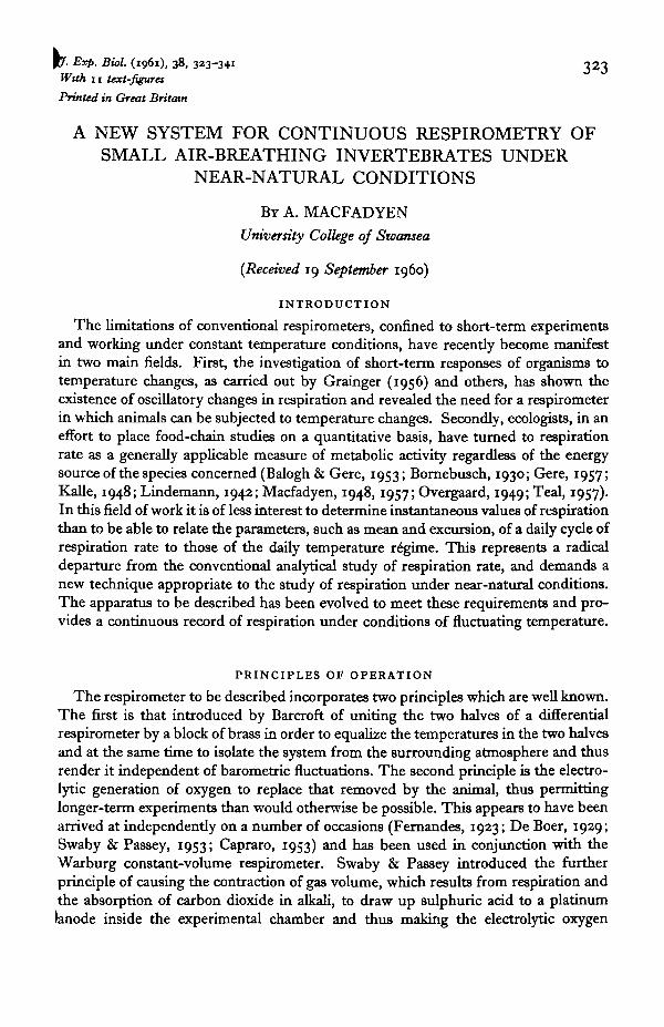
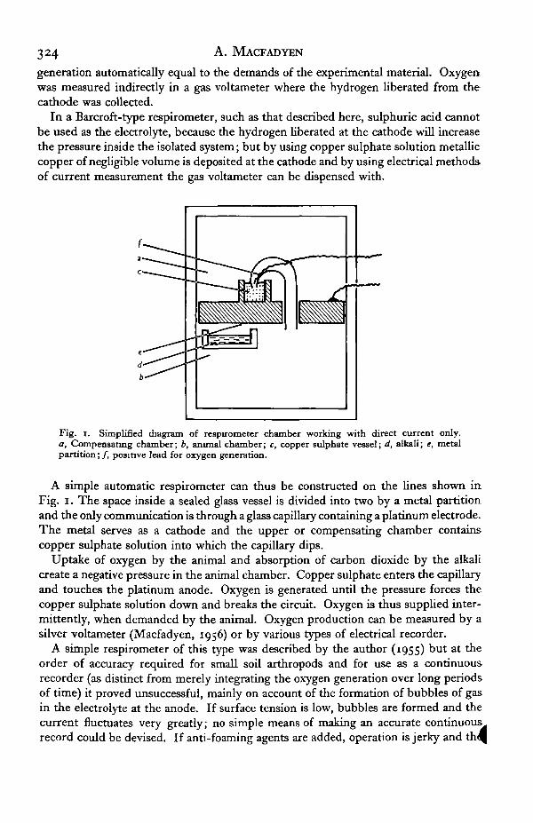
Fig. i. Simplified diagram of respirometer chamber working with direct current only.a, Compensating chamber; b, animal chamber; c, copper sulphate vessel; d, alkali; e, metalpartition; /, positive lead for oxygen generation.
A simple automatic respirometer can thus be constructed on the lines shown inFig. i. The space inside a sealed glass vessel is divided into two by a metal partitionand the only communication is through a glass capillary containing a platinum electrode.The metal serves as a cathode and the upper or compensating chamber containscopper sulphate solution into which the capillary dips.
Uptake of oxygen by the animal and absorption of carbon dioxide by the alkalicreate a negative pressure in the animal chamber. Copper sulphate enters the capillaryand touches the platinum anode. Oxygen is generated until the pressure forces thecopper sulphate solution down and breaks the circuit. Oxygen is thus supplied inter-mittently, when demanded by the animal. Oxygen production can be measured by asilver voltameter (Macfadyen, 1956) or by various types of electrical recorder.
A simple respirometer of this type was described by the author (1955) but at theorder of accuracy required for small soil arthropods and for use as a continuousrecorder (as distinct from merely integrating the oxygen generation over long periodsof time) it proved unsuccessful, mainly on account of the formation of bubbles of gasin the electrolyte at the anode. If surface tension is low, bubbles are formed and thecurrent fluctuates very greatly; no simple means of making an accurate continuousrecord could be devised. If anti-foaming agents are added, operation is jerky and

Continuous respirometry under near-natural conditions 325
results are inaccurate. For larger animals and greater rates of respiration an all-d.c.respirometer on these lines is quite feasible, as has recently been shown by Wintering-ham (1959), who, however, does not use a compensating chamber.
Fig. 2. Simplified diagram of respirometer chamber working with separate pressure-detectingand oxygen-generating electrodes, a-f, As in Fig. i ; g, lead to pressure-detecting electrode;h, pressure-detecting electrode; j , lead to compensating oxygen generator; k, compensatingcopper sulphate vessel; /, compensating alkali vessel; m, tnode amplifier; n, relay for switchingon d.c. to c.
A more accurate and sensitive respirometer can be constructed by separating thetwo functions of oxygen generation and pressure-change detection at two differentelectrodes as, for example, in Fig. 2. The only change introduced here is that pressurechange is detected by an electrode which is connected in a bridge circuit supplied withalternating current. By using a thermionic valve as detector very low currents arepassed, polarization of the electrode is prevented and small changes in the level of themeniscus can be detected. Such a change results in the valve relay closing and switch-ing on direct current to the anode in the copper sulphate solution in the animalchamber. It will be noticed that in this version the compensating chamber containsduplicate vessels for both alkali and copper sulphate. These are necessary to preventspurious gas-volume changes when temperature changes are made (see below). Theyare also important at the start of an experiment because carbon dioxide in the com-pensating chamber is absorbed at the same rate as in the experimental chamber; thetwo oxygen generators can be used in turn to bring the meniscus in the pressure-detecting electrode to its working position.
With the basic layout of Fig. 2, and using a vessel of 25 cm.8 capacity in each half,sufficient accuracy can be achieved for measuring respiration rates of small arthropodsof the order of 1 mg. weight. In order to increase accuracy various other principleswere investigated, including those advocated by Burk & Hobby (1954) in their hydro-static amplifier respirometer and 'paradox' respirometer. These attempts failed toincrease sensitivity possibly because the principles which they employ cannot be
^ to the Barcroft-type respirometer. The increased sensitivity needed for small
326 A. MACFADYEN
species down to about o-oi mg. weight is obtained instead by the use of scaled-downversions of the respirometer herein described, together with improved methods ofpressure-change detection.
A PRACTICAL A.C. RESPIROMETER
The various elaborations of the arrangement illustrated in Fig. 2 which are requiredto produce a workable instrument can be considered under two main headings: thedesign of the respirometer vessel itself and that of the control and recording system.The various component parts of these will now be considered in turn.
(a) The design of the respirometer chamber (Fig. 3)
The effects of temperature change
In order that temperature changes shall not produce different rates of expansion inthe animal and compensating chambers the following principles must be observed inpractice:
(1) The two chambers should be as similar as possible in size, shape and construc-tion so that rates of heating of both gases and liquids will be the same. If the volumesand surface areas of liquids are different, transient differences in vapour pressure willoccur as the temperature changes. The magnitude of such differences is correlatedmore closely with the acceleration than with the velocity of temperature change.
(2) The chambers must be thermally united by a good conductor and madeindependent of room temperatures by insulation or by submergence in a water-bath.Thick glass walls used in earlier models were found to be inadequate as insulators whenused in air in a 'constant temperature' (i.e. + i° C.) room. Since electrically conduct-ing leads must pass into the chambers these leads must be as long and thin as possibleand arranged symmetrically.
Spurious gas absorption is an important factor to be guarded against in the design ofthe chambers. This can occur at rates much greater than the respiration rates beingmeasured, due to (1) the use of water which is not fully aerated (e.g. recently distilledwater) in making up solutions, and (2) chemical oxidation of metal when in contactwith dilute alkali. The remedy for the first trouble is obvious. The second has beenovercome by the use of titanium or copper, plated first with silver and then withrhodium, for all metal parts.
The strength of the solutions used in the chambers is determined by two factors: theenvironmental demands of the animals, and the balance of vapour pressures. Saturatedcopper sulphate solution is in equilibrium with air at about 98 % relative humidity andso is 4 % alkali, so that no distillation between these solutions occurs. Furthermore,most terrestrial invertebrates thrive in humidities of this order. If drier conditions arerequired and stronger alkali is used the surface of the copper sulphate chamber mustbe made as small as possible. If the respirometer were used with aquatic animals, byplacing them in dishes of water inside the chamber, the vapour pressure balance mightbe upset and the thermal capacity of the animal chamber would certainly be increased:both these effects could presumably be balanced by a similar dish in the compensatingchamber.
The low level of carbon dioxide in the air results in somewhat artificial condition^

Continuous respirometry under near-natural conditions 327
for the animals, as in most other respirometers. It is proposed to rectify this by theuse of carbon dioxide buffers (Umbreit, 1957), but these have not yet been tried.
The pressure-detecting system is simply a switch which causes oxygen generation to bestarted or stopped with a minimal change in pressure. In principle a non-conductingcapillary coated with a thin layer of a noble metal could be used but no fully satisfactorycoating has yet been produced. A Pyrex glass capillary with a fine platinum electrodefused in the glass has been found to be chemically and mechanically reliable. At firstthe wire was carefully centred in the capillary but this resulted in discontinuous opera-tion. If the wire is arranged to touch the side (as in Fig. 8) a film of dilute alkali isstretched between the wire and the bulk of the fluid. The controller is sensitive to a
Scale: 1 cm.
Fig. 3. Section through plastic type respirometer of 2*5 c.c. capacity. Animal chamber on theleft, compensating chamber ori the right. The remaining half is similar except that the smallvessels c and g are balanced by similar ones containing alkali (for temperature compensation).The animals rest on a gauze or in a glass chamber (not shown) within the left-hand chamber.The lid (not shown) is held in place by wing nuts on three screws; these screws also hold inplace the bottom piece n. The cut surfaces of the titanium (or rhodium-plated copper) bars areshaded; these are bolted to a common copper heat-sink which may be immersed in a water-bath, a, Lead to pressure-detecting electrode; b, oxygen-generating electrode, compensatingchamber; c, oxygen-generating cell containing copper sulphate solution; d, glass bulb ofpressure-detecting electrode; e, alkali vessel of compensating chamber; / , capillary tube ofpressure-detecting electrode; g, oxygen-generating cell, animal chamber; h, synthetic rubber' O '-ring; j , spare connexion for use with thermistor and included for heat balance; k, alkalivessel, animal chamber; /, titanium (or rhodium-plated copper) bar in the top of which vesselsare drilled; m, main body of respirometer made from styrene/rubber (Styron 475); n, bottomplate of respirometer made from Perspex; o, insulating tubes of Perspex.

328 A. MACFADYEN
change of approximately 3000 Q, in 25,000 Q. so that the stretching and contraction ofthe film can cause the oxygen to be switched on and off without the film being brokenor the column being sucked into the narrow region above the tip of the wire. Used inthis way, operation of the oxygen generator results from barely perceptible changes ofliquid level. There is no advantage to be gained from making the capillary diameterless than about o-8 mm.
The use of plastics was approached very cautiously, especially in view of reports thatthese can be highly toxic (see Jeanson-Luusinang, 1958). However, the materialsreferred to were the earlier plastics such as polyvinyl chloride which contain largequantities of toxic 'plasticisers'. Polystyrene can be produced without the incorpora-tion of plasticisers and an impact-resistant grade containing rubber (Styron 475) wasfound to have no effect on longevity of mites kept in a vessel lined with this materialand to be well suited to the present purpose.
The plastic respirometer vessel has the following advantages:
(1) Almost perfect thermal symmetry. Transient spurious uptake rates of less than0-2 mm.8/hr. are produced by temperature changes of i° C./hr. and accelerations of50 C./hr.2. These results could be further improved if necessary by adjustment ofsolutions in the two chambers.
(2) The actual vessels are not submerged in the water-bath, and animals can beobserved during experiments without disturbance. They can also be given any desiredlight regime. It should be noticed, however, that the sensitivity of the apparatus issuch that the thermal conduction of the £ in. Perspex lid cannot be neglected. A strongdraught or a finger placed asymmetrically on the lid will cause an immediate spurious'uptake' or 'generation' of gas.
(3) The vessels are robust and very easily loaded and emptied. They stay suspendedabove the water-bath, and connected to the controller in a normal room; they can bechanged in 2 or 3 min. While the lid is being screwed down, the conductivity of thepressure-detecting electrode is monitored. If the meniscus is too low, the screw on theanimal chamber side is screwed down until it rises and then that on the other side, sothat the meniscus starts close to the working position. Final adjustment is made bygenerating oxygen alternately in the two chambers and, as a result, recordings canbegin within a few minutes.
(4) Ease of construction. All the parts can be made without difficulty on a smalllathe, and small (sensitive) vessels are no more difficult to make than larger ones. Sofar, vessels from 2-5 to 20 c.c. capacity have been made without difficulty.
(b) The design of the control and recording system
In principle this is as follows:
A timing mechanism, driven by a synchronous electric motor, 'interrogates' therespirometer at regular intervals, 'offering' oxygen. This process will be referred to asthe cycle. If at the beginning of the cycle oxygen is required (as indicated by the posi-tion of the alkali meniscus in the capillary) the oxygen-generating current is switchedon and continues to flow until the next 'interrogation' at the beginning of the nextcycle. If the 'no more oxygen required' signal is given in the middle of an 'on' cycle(i.e. a cycle during which the oxygen-generating current is flowing) the current is

Continuous respirometry under near-natural conditions 329
switched off until the' interrogation' at the beginning of the next cycle; similarly, if the'oxygen required' signal is given in the middle of an 'off' cycle the current is notswitched on until the' interrogation' at the beginning of the next cycle. Oxygen is thussupplied in units or 'doses'. Records are made by perforation of a moving strip ofpaper. On the time track a mark is made at the beginning of each cycle; on therespirometer track a mark is made at the beginning of each ' on' cycle. The respiratoryrate is calculated from the mark/space ratio on the respirometer track, taken over someconvenient number (usually 30) of cycles.
Fullrate
505-0
Time5-0
1O010
•| £x 1-0-0-97 •
• H &x 5-0-1-33 • • • •
1100 .
• •
• •
•1-11
•I
10-55
Fig. 4 a. Copy of a record of a respiration experiment marked to show the manner of calculat-ing respiration rates The pre-set rates at which oxygen would be generated if switched oncontinuously are shown on the right.
Fig. 46. The same record as 4a with 'batching' circuits in operation (see p. 339).
In this system the control and recording of six respirometers involves three separatepieces of equipment, the full details of which are given in Appendix 2 (Figs. 9, 10).They are briefly:
(a) An amplifier enabling the signal corresponding to the position of the meniscusin the pressure-detecting electrode to open or close an electromagnetic relay; thecircuit for this differs from that in Fig. 2 mainly in that a pentode amplifier is used andthat the switching of the oxygen-generating direct current is over-ridden by the timingmechanism so that closing and opening of the relay can only occur at set times.Various switches and controls are provided so that the current can be controlled andmetered.
(b) A timing mechanism. This involves a switch, driven by a synchronous motor,and a number of relays so arranged as to govern the operations of the oxygen-generat-ing cells in the respirometers and to send signals to the recorder in order to wind on thepaper and make a mark when the appropriate cell has received a supply of oxygen.
(c) A recorder. This consists of a solenoid-operated drive for the paper and sevenPBolenoid-operated markers equipped with steel gramophone needle tips which prick
21 Exp. Biol 38, 2
33° A. MACFADYEN
the paper. Six of the markers correspond to the six respirometers and produce marksevery time oxygen is provided. The seventh provides a time track which is marked atthe beginning of each cycle, i.e. every time oxygen is ' offered'. This track is interruptedevery 30 cycles by a cam-operated switch coupled to the paper drive; the resulting gapsat about 3 in. intervals facilitate the reading of the record. An example of an actualrecord is produced in Fig. 4a, in which the time track is central and the 30-cycle gapsrepresent ends of 5 min. intervals. The record can be read in many different ways butthe following method is usually adopted.
(1) The oxygen supply current of each respirometer is set to a certain rate such that,if oxygen were continuously demanded, the rate of supply would be a whole numberof cubic millimetres per hour. (The meter of Fig. 9 is directly calibrated in these unitsat a number of fixed temperatures.) The rate chosen is about twice the maximum antici-pated demand so that oxygen will be accepted for about 50 % of the time.
(2) The ratio of occasions when oxygen is accepted to the total number when it isoffered (30) can be measured for each 5 min. period and the ratio multiplied by thechosen rate (item 1).
(3) However, strict adherence to this rule may result in an apparent periodicity inrespiration rate since ' acceptances' may occur in groups which succeed one another atintervals of more or less than 5 min. It is therefore preferable to modify the method ofreading. A reading period is arbitrarily considered to start with the first of a group ofmarks and to end with the last of a group of spaces. During this period the ratio ofmarks to marks plus spaces (not necessarily 30) is multiplied by the rate factor and isrecorded for the corresponding 5 min. period. The record in Fig. 4 a has been markedwith time of day and fractions as read. The reading process is facilitated by the use of aruler calibrated to fit the punch marks.
PERFORMANCE
A. Performance at constant temperature
(i) Sensitivity. A limit to performance is set by the volume-sensitivity of therespirometer which is in turn determined by (a) the size of the chambers, and (b) thesensitivity of the pressure-detecting system. With 2-5 c.c. chambers the change involume required to turn the oxygen supply on or off is of the order of o-1 mm.3.
The size of the respiratory chamber is set by the size of the animal. The sensitivityof the pressure-detecting system depends upon the diameter of the capillary and uponthe amplification factor; in both these directions there is scope for[improvement if thisbecomes necessary.
(ii) Stability. Within the limits of sensitivity stability is complete. That is to say, ifthe respirometer is set up without any respiring tissue and with the capillary meniscusin the working position it will remain so indefinitely.
(iii) Accuracy. The record shows the number of 'doses' of oxygen supplied in agiven time, and the accuracy of the method in terms of rate of oxygen consumptiondepends upon the accuracy with which the amount of oxygen supplied in a ' dose' isknown. The electrochemical equivalent of oxygen is of course known with a highdegree of accuracy. The evolution of oxygen from copper sulphate solution at the lowrates here used has been tested in a modified Warburg apparatus and no depar tur^

Continuous respirometry under near-natural conditions 331
from theoretical expectation has been found. The accuracy is therefore determined inpractice by (a) the stability of the oxygen-generating current, (b) the accuracy withwhich it is measured, (c) the extent of electrical leakage in the associated circuits and(d) the accuracy with which time is measured. The following steps have been taken toaccount for these factors:
(a) The use of a large-capacity 6 V. dry battery, partially discharged, as an indepen-dent source and the use of a high resistance in series with the copper sulphate cell.(b) The calibration of the good quality moving-coil meter using a Tinsley potentio-meter and the avoidance of current values involving small deflexions. This is probablythe weakest link in the chain at present and may limit accuracy to ± 3 % but a moreaccurate meter could be used if the nature of the experiments demanded it. (c) This isa matter of careful construction and regular checking of respirometers before use, butno serious trouble has been experienced in practice, (d) The synchronous motorrunning from 50 c./s. mains is unlikely to vary by more than 1 %, but a clockworkmovement could be substituted if necessary. There remains the possibility thatalthough the timing mechanism itself may be accurate the operation of the switch gearmay involve some delay and thus curtail the time during which the oxygen-generatingcurrent flows. As is explained in the Appendix, the time lost in this way is not morethan 0-2 sec. (2 % of a 10 sec. dose). This loss could be reduced if necessary in moreaccurate work.
As a check on the level of accuracy of the whole respirometer, comparative trialswere carried out with a Warburg respirometer (Shandon with 15 c.c. reaction vessels).Disks of carrot root (6 mm. diameter x 2 mm. thick, weight about 8 mg.) were used.The mean respiration rates over a 4 hr. period were:
Warburg: 1-35, 1-02, 0-67, 1-19 mean i-o6± 0-29 mm.8/hr./mg.
New respirometer: i-oo, o-8i, 1*29, 1-48, 1-15 mean 1-14 ± 0-26 mm.8/hr./mg.
Similar results were obtained in other trials and it was concluded that there was nodifference in absolute level of accuracy between the two respirometers.
Any method which involves measurement of amount of oxygen consumed in a finitetime interval must inevitably lag upon events when the rate of oxygen consumption ischanging. If the time interval is reduced the lag is reduced, but at the expense ofaccuracy. The errors thus occasioned can be calculated from the sensitivity of therespirometer and from the following parameters which can be varied at will so as toprovide the most acceptable compromise: (a) the strength of the oxygen-generatingcurrent; (b) the duration of the cycle; (c) the number of cycles over which the rate ofoxygen consumption is calculated.
B. Performance tmder changing temperature
The effect of change of temperature on a respirometer with a compensating chamberis to produce movements in the connecting capillary due to changes in gas expansionand vapour pressure in the two chambers. In a symmetrical apparatus such movementsare transient and can usually be correlated with either the acceleration or the velocityof temperature change. An example of such an effect is shown in Fig. 5 a. If tempera-ture changes are not to produce effects of this kind, the two chambers must be con-
nected by a good thermal conductor, and preferably some inertia in the form of high

332 A. MACFADYEN
thermal capacity should be present in the system. The plastic type of respirometercontains a total of 400 g. of copper (thermal capacity about 40 cal./° C.) and the rate ofconduction between each chamber and the water-bath is about 5000 times as great asthat through the plastic and the leads. The surface areas of the fluids present in thedepressions in the copper rods are independent of the volume, but if volumes are
080706
0-4030201
30-20
10
1-0-20-30-50-
u+0-
10
Temperature °C.
Rate of change of temperature, °C /hr.
Respiration rate, mm.3/hr.
"i r n 1 1 1 1 r~ i i10 mln. Intervals
1 r
1-s -
U -
13-12-11-
8-
Temperature, ° C .
Respiration rate, mm.Vhr. # # . #
\ I T10 mln. intervals
r i 1 1
Fig. 5. Graphs to show spurious changes in respiration rate, produced by changes in tempera-ture, (a) Temperature, rate of change of temperature and readings from earlier glass type ofrespirometer. (6) Temperature and readings from compensated plastic type of respirometer.

Continuous respirometry under near-natural conditions 333
markedly unequal they affect the thermal inertia of the chambers in a predictablemanner (the gas in the chamber containing least fluid expands faster as the temperatureof the whole system is raised). For normal purposes the chambers may be filled withequal volumes of fluids as judged by eye, but when large rates of temperature change areto be made, preliminary experiments must be carried out in which the volumes areadjusted to produce a negligible spurious response. In this way rates of change of5° C./hr. and accelerations of 250 C./hr.2 have been shown to produce spurious effectsof less than 1 mm.3/hr. and lasting for less than 10 min. (Fig. 5 b). There is no reason tosuppose that these results could not be improved on, but these figures correspond tofaster changes of temperature than have been required up to the present.
RESULTS
Experiments to date have been confined to constant temperatures maintained to+ 0-02° C. by a Sunvic thermostat, relay and proportionating head; but a thermostatgiving sinusoidal temperature cycles of controlled amplitude has also been constructedand will be described in due course. Temperature can be measured in the water-bath orinside the respirometer by mean9 of a thermistor. A number of results have beenobtained with invertebrates of different sizes and, whereas some species show littlediurnal variation in rate, others show marked changes, a phenomenon which is thoughtnot to have been reported before in terrestrial invertebrates. Some typical results aregiven in Figs. 6 and 7.
13-
12-
11-
10-9-
i 8-m 7 -
E 6 -
5-
4-
3-
1514
*. 13
12
11
i 10'ft. ^ " 9\ / E
V V • E 8
"V* 5
18 24 6 12 18 24 6 12Hours
-•
- •
* • • • • ••
• • " •
- • v«" v * ' ••* • •• • • ' . • v .--
1 1 1 1 1 1 1 1 1 16 12 18 24 6 12 18 24 6 12
Hours
Fig. 6 Fig. 7Fig. 6. The first two complete diurnal cycles of respiration taken from a 4-day experimenton Platyhtmu triangidaru, $ pre-adult. This experiment was exceptional in showing arapid decrease in mean rate (at the end of 4 days the animal was alive but respired at only0-2 mm.'/ hr.). Temperature 190 C.
Fig. 7. The final ai days of a 5-day experiment on Orascut asellui showing a tendency to highrates about dawn. Temperature 180 C.
Applications
The respirometer is intended for investigations in which long-term measurements atvariable temperatures are required. In the case of water-living forms such as ProtozoaB i d Nematoda the Cartesian diver respirometer (Holter, 1943; Linderstram-Lang, 1943)
334 A. MACFADYEN
has greater sensitivity and gives consistent results (Overgaard, 1949). The morecomplex reactions of air-breathing animals and their dependence on diurnal tempera-ture and light cycles for normal activity (Cloudsley-Thompson, 1951 a, b) demand thesimulation of these cycles and the use of continuous recording during longer experi-ments. The study of acclimatization and reactions to sudden changes of temperaturehas only recently been attempted (Grainger, 1956; Kerkut & Taylor, 1956) and exist-ing types of respirometer are unsuitable. It is hoped that in these two fields which arecommon to physiology and ecology the new apparatus may prove particularly useful.In addition, the recording facility may well prove of use in more conventional respiro-metry, especially where a number of experiments are to be run simultaneously. Thereis no reason to suppose that the limits of accuracy, sensitivity and independence offluctuating temperature have yet been approached. The cost of the complete apparatuswith six plastic chambers is certainly less than £50 for materials.
SUMMARY
1. A new system of respirometry for long-term experiments on small air-breathinginvertebrates is described for use in work where changing temperature conditions areessential. There is no reason why the same system should not be used for largeranimals.
2. The respirometer is of the Barcroft, compensating type, isolated from the atmo-sphere, and has provision for temperature equilibration in the two vessels.
3. Oxygen is automatically replenished by electrolysis of copper sulphate solution inthe chamber as it is used by the animal and the rate of replenishment is recorded.
4. The main features in design of such an apparatus, its limitations and accuracyare discussed. The accuracy is comparable with that of a Warburg respirometer and thesensitivity, at better than o-1 mm.8 of oxygen/hour, is about ten times as great.
5. A special control and recording system has been developed in order to reduceexpense and simplify the interpretation of the data from six respirometers over longperiods.
6. It is shown that the errors arising from temperature changes can be reduced toacceptable levels for most purposes. The apparatus is therefore suitable for use in thestudy of acclimatization and of responses to rhythmical temperature changes.
7. Examples of respiration records are given which illustrate the possibilities ofbeing able to follow respiration rates through several diurnal cycles.
8. Practical details of construction are given in the appendices.
The need for a respirometer of this nature first became clear to me after discussionswith Mr Charles Elton, F.R.S., in about 1951. It is thanks to his encouragement andthe patient advice of my colleagues, both in the Bureau of Animal Population, Oxford,and in the Botany and Zoology Departments at Swansea, that the demands of aseemingly impossible specification have been met. An earlier draft of this paper wasseen by Prof. V. B. Wigglesworth who made many suggestions and criticisms whichhave resulted in radical improvements both to the apparatus and to the paper. ImperialChemical Industries, Waunarlwydd Titanium Plant, generously supplied titanimetal, and British Resin Products, Research and Development Division, kindl|
Continuous respirometry under near-natural conditions 335
produced the polystyrene blocks. Messrs Edwards High Vacuum Ltd. gave advice onthe use of' O' rings, waxes, and silicone greases. Mr Tweedy, manager of South WalesTransport Co. Ltd., and his colleagues advised me on the use of T.I.M. bus ticketpaper and arranged for a supply. To all these people I am duly grateful; and also to mywife whose encouragement and advice have been constant through many set-backs.During the first period of this work I was in receipt of a grant from the NatureConservancy, to whom I am most thankful.
APPENDIX I
Construction of the plastic respirometer vessels (Fig. 3)
(Note. A list of suppliers of equipment and materials is given at the end ofAppendix 2.)
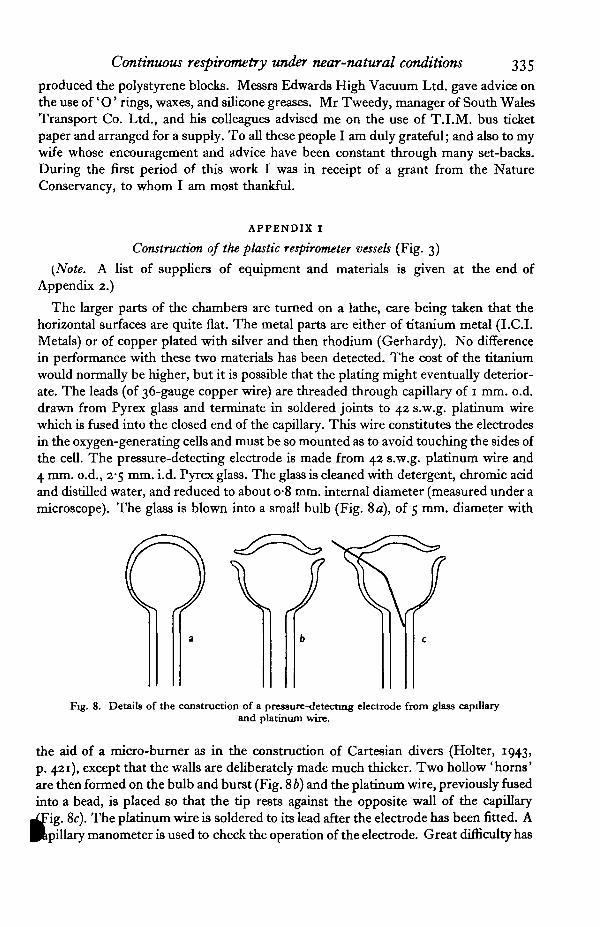
The larger parts of the chambers are turned on a lathe, care being taken that thehorizontal surfaces are quite flat. The metal parts are either of titanium metal (I.C.I.Metals) or of copper plated with silver and then rhodium (Gerhardy). No differencein performance with these two materials has been detected. The cost of the titaniumwould normally be higher, but it is possible that the plating might eventually deterior-ate. The leads (of 36-gauge copper wire) are threaded through capillary of 1 mm. o.d.drawn from Pyrex glass and terminate in soldered joints to 42 s.w.g. platinum wirewhich is fused into the closed end of the capillary. This wire constitutes the electrodesin the oxygen-generating cells and must be so mounted as to avoid touching the sides ofthe cell. The pressure-detecting electrode is made from 42 s.w.g. platinum wire and4 mm. o.d., 2-5 mm. i.d. Pyrex glass. The glass is cleaned with detergent, chromic acidand distilled water, and reduced to about o-8 mm. internal diameter (measured under amicroscope). The glass is blown into a small bulb (Fig. 8 a), of 5 mm. diameter with
Fig. 8. Details of the construction of a pressure-detecting electrode from glass capillaryand platinum wire.
the aid of a micro-burner as in the construction of Cartesian divers (Holter, 1943,p. 421), except that the walls are deliberately made much thicker. Two hollow 'horns'are then fonned on the bulb and burst (Fig. 8 b) and the platinum wire, previously fusedinto a bead, is placed so that the tip rests against the opposite wall of the capillary
. 8c). The platinum wire is soldered to its lead after the electrode has been fitted. Apillary manometer is used to check the operation of the electrode. Great difficulty has

336 A. MACFADYEN
been experienced in producing gas-tight joints which can stand thermal expansion andoccasional wetting with alkali. The main joints are made with rubber 'O ' rings (Edwards)and these, provided that the maker's specifications are followed, have proved completelygas-tight as well as permitting dismantling of the apparatus if necessary. The jointsbetween the polystyrene block and the glass capillaries are made with a polystyrenecement (suggested to me by Mr Hayward and described by Lund, 1949), containing15 g. polystyrene, 5 ml. dibutylphthalate and 30 ml. xylol. This cement is veryreliable but it should be allowed at least 3 days to dry and to allow the plasticiser toevaporate. The junction between the lid and the body of the respirometer is sealed withEdwards High Vacuum Silicone Grease.
A variety of experimental chambers can be placed inside the respirometer accordingto need. Immobile materials can be placed on a coverslip cut to allow passage of air.Larger animals can rest on a piece of stainless steel gauze provided that faeces will notfall into the solutions below. Alternatively, simple cells can be made from hangingdrop rings and coverslips. In experiments with carrot slices it was found that thesebecome desiccated when placed on a gauze above 4 % and even 1 % alkali, but whenone side rested on a piece of coverslip the rate of desiccation was very greatly reduced.
APPENDIX 2
The control apparatus (Fig. 9)
(1) The amplifier. This has a.c. supplied to both anode and grid so that when thetwo supplies are in phase, anode current flows; when in antiphase the valve does notconduct. The screen is supplied with 180 V. d.c. which was found empirically to givegreatest sensitivity under these conditions. The transformer supplying the bridge inthe grid circuit of the valve is connected so that, when the pressure detector is on opencircuit, the grid is supplied with 18 V. in antiphase to the anode; as the impedancebetween the pressure-detecting electrode and the earth connexion falls below 28,000 Othe phase is reversed, the valve conducts and the anode relay opens. The anode circuitresembles a normal power pack smoothed by resistance and condenser.
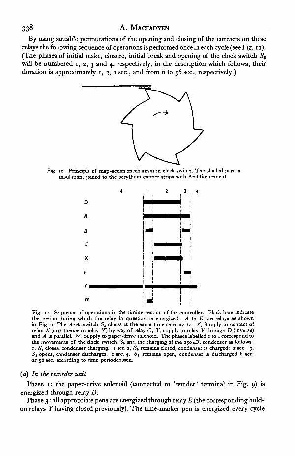
(2) The timing mechanism is governed by a self-starting synchronous electric clockmotor (surplus stores) which closes a switch 55 for about 3 sec. once in each cycle.A snap-action mechanism in this switch is essential to prevent multiple firing andsparking (Fig. 10). The motor drives a cam cut from brass which during most of theperiod rubs on the lower piece of beryllium copper; this piece is cemented withAraldite (Aero Resins Ltd.) to a piece of laminated resin plastic, and this in turn to theupper spring of beryllium copper which is the live contact of the switch. The cam isconnected to earth by a slip-ring. Only when the spring has been fully raised does thetip of the cam make a snap connexion with the spring itself. The circuit is openedequally suddenly as the spring falls from the tip of the cam point.
Relay D is driven directly by Sb; one of the contacts applies a negative potentialto the common point between relay A on the one hand and the 25O/iF. condenserin series with relay B on the other. As the condenser charges up on the closing (anddischarges on the opening) of the clock switch S&, relay B closes; otherwise it is open.The condenser discharge also maintains relay A open for a while after the clock switc||has opened.

A. MACFADYEN
By using suitable permutations of the opening and closing of the contacts on theserelays the following sequence of operations is performed once in each cycle (see Fig. 11).(The phases of initial make, closure, initial break and opening of the clock switch 5S
will be numbered i, 2, 3 and 4, respectively, in the description which follows; theirduration is approximately i, 2, 1 sec., and from 6 to 56 sec, respectively.)
Fig. 10. Principle of snap-action mechanism in clock switch. The shaded part isinsulation, joined to the beryllium copper strips with Araldite cement.
D
A
8
C
X
£
r •
W UFig. 11. Sequence of operations in the timing section of the controller. Black bars indicatethe period during which the relay in question is energized. A to E are relays as shownin Fig. 9. The clock-switch St closes at the same time as relay D. X, Supply to contact ofrelay X (and thence to relay Y) by way of relay C; Y, supply to relay Y through D (inverse)and A in parallel. W, Supply to paper-drive solenoid. The phases labelled i to 4 correspond tothe movements of the clock switch 5, and the charging of the 250/iF. condenser as follows:1, Sg closes, condenser charging. 1 sec 2, St remains closed, condenser is charged: 2 sec 3,St opens, condenser discharges. 1 sec 4, 5 , remains open, condenser is discharged 6 sec.or 56 sec according to time periodchosen.
(a) In the recorder unit
Phase 1: the paper-drive solenoid (connected to 'winder' terminal in Fig. 9) isenergized through relay D.
Phase 3: all appropriate pens are energized through relay E (the corresponding hold-on relays Y having closed previously). The time-marker pen is energized every cycle
Continuous respirometry under near-natural conditions 339
except that once every 30 cycles the circuit is interrupted by a switch on the film driveunit so that a gap is left which facilitates reading the record.
(b) In the amplifier circuit
As explained previously the function of the timing mechanism is to ensure thatoxygen is generated for definite periods of time. When respiration causes the gridresistance of the amplifier to rise and the anode relay (X) to close nothing happens untilthe end of the current phase (4). When the clock switch 56 closes, first after a delay ofone second relay C closes and then relay Y closes. The contacts on this relay performthree functions: (i) the coil of relay Y is supplied direct with d.c. and cannot then beopened during the ensuing period regardless of what happens to the anode relay; (ii)the circuit to the corresponding pen solenoid is completed so that, when relay E closesduring phase 3, this pen will make a punch mark; and (iii) direct current is switched tothe positive electrode in the copper sulphate cell in the respirometer, thus generatingoxygen.
This state of affairs persists for the remainder of phase 4. During phase 1 of the nextcycle (see Fig. 11) the direct positive supply to relay Y through its own contacts isinterrupted—by relay D—for about 0-2 sec only. If relay X at this time is still closed afurther period of oxygen generation will follow, but if it has opened as a result of nomore oxygen being required, relay Y will remain open for the ensuing period.
(c) Additional facilities
Temperature in the respirometer cells can be measured by thermistors whose resis-tance can be recorded by any suitable recording milliammeter. An inexpensive devicefor this purpose has been described (Kempson & Macfadyen, 1954) in which theposition of a microammeter needle is recorded on film. The timing and control sectionsof the present apparatus can be substituted for those of the temperature recorder sothat only the camera and circuit selector of the recorder need be used. Alternatively,the thermistors can be connected directly to a bridge circuit metered by a high-resistance recording milliammeter such as the Fielden servograph; this has been doneand it provides a very accurate and easily read record but is limited to reading fourthermistors only. Again, if mean temperatures only are required a temperatureintegrator (Macfadyen, 1956) can be used.
Batching mechanism. At the cost of some loss of sensitivity the reading of the paperrecord can be made easier by batching all the marks for a given set of 30 cycles at thebeginning of the set. This has the effect of making the paper read like a series of histo-grams as in Fig. 5 b. The anode relay is made to lock itself open as soon as any gap inoxygen demand occurs and to stay open until the end of the set of 30 cycles. At theend of the set the relay is allowed to close and the pent-up demand for oxygen is thensatisfied during the next set of cycles. The locking-open is done by connecting theotherwise unused contact on the X relay to the grid circuit of the same valve; interrup-tion of the screen current to all valves by relay F restores the relay AT to a closed posi-tion. This device is best used with a cycle of 10 sec. duration and even then the meanlength of the 'off' period is increased to 2\ min. with a corresponding decrease insensitivity. A switch (54) is provided to maintain the screen supply and cut out theJbacthing mechanism when not required.
34-o A. MACFADYEN
(3) The metering and switching section. Switch Sx provides facilities for (a) meteringthe voltage drop across the anode relays of the six amplifiers by switching and thuschecking on the correct operation of these circuits, (b) for inserting the 4 in., 50 micro-ampere meter in the oxygen-generating circuits in order to set the rate of oxygensupply. The accuracy of this meter is not very high, and for more careful work thanhas been attempted so far a better class instrument could be used. Two ranges areprovided covering 1-11 and 10-100 mm.3/hr. oxygen rates. The face of the meter isdirectly calibrated in these units at io°, 150 and 200 C. respirometer temperature. Anadditional meter position provides for a check on the continuity of the oxygen-generating circuits.
52 selects from the six circuits that circuit whose operation is being monitored by .S .̂53 is repeated for each circuit and is used to select a fast or slow rate of oxygen
generation (further controlled by the 220 K resistor). Further positions are used toapply a ' force' voltage (at 30 mA.) to either of the oxygen generators during initialsetting up so as to bring the liquid in the pressure-detecting electrode to its workingposition.
(4) Components. Most components used in the control unit were derived fromgovernment surplus sources or were bought from Radiospares Ltd. The heavy-dutyrelay E (from Londex Ltd.) handles the solenoid currents, the remaining relays are ofPost Office type, all with 200 £2 coils except the relays X (5000 Q) and relay B(500 £}). Relays Y have heavy-duty contacts. Condensers are of paper block typeexcept the two high values which are electrolytic. Resistances are of standard carbontype except for the 220,000 Q. variable controls which are of the pre-set wire woundtype (Egen Electric Ltd.).
(5) The marker unit. The mechanical details of this unit will depend on availablematerials; the main points of design concern the paper wind and the solenoids. Busticket paper 1-5 in. (38 mm.) wide was chosen as a cheap recording medium (6 rolls atzd. each are used in a week with cycles of 10 sec. duration), but it is not so easy to use asperforated film which can be driven by a sprocket wheel and is more rigid. Difficultywas experienced in achieving consistent spacing and in preventing sideways movementand creasing of the paper. These faults can be corrected by arranging for the paper topass between rollers, of which one is driven by a solenoid and ratchet mechanism andthe other (of small diameter) is freely floating in guides but mounted on a spindle whichis pulled by strong springs towards the spindle of the driven roller. The unused roll ofpaper should rest in a box whose sides help to guide the paper towards the rollers. Themarking needles are mounted on rocking arms whose other ends are pulled downwardsby springs and upwards by solenoids (Phillips Control). These are of a type (41 \i\izDC) intended for intermittent use on 12 V. d.c. and provide ample force for the purpose.In fact, it is advisable to connect them in series with a 2 ii resistance to reduce thepenetration of the needle and this may usefully take the form of a Post Office counterwith parallel resistance.
List of suppliers
Aero Research Ltd., Duxford, Cambridge.British Resin Products, Research and Development Division, Barry, Glamorgan.Edwards High Vacuum Ltd., Manor Royal, Crawley, Sussex.

Continuous respirometry under near-natural conditions 341
List of suppliers (cont.)
Egen Electric Ltd., Charfleet Estate, Canvey Island, Essex.Fielden Electronics Ltd., Wythenshawe, Manchester 22.I.C.I. Metals Division, Titanium Plant, Waunarlwydd, Swansea, Glamorgan.Johnson Mathey and Co. Ltd., 78 Hatton Gardens, London, E.C. 1.Londex Ltd., 207 Anerley Road, London, S.E. 20.National Cash Register Co., North Circular Road, London, N.W. 2.Phillips Control (G.B.) Ltd., Farnborough, Hants.
REFERENCES
BALOOH, J. & GERE, G. (1953). tjber die ErnShrungsbiologie und Luftstickstoff-bindung der Hyphantria-raupen. Ada Biologica Acad. Sci. Hung. 4, 431-52.
BORNEBUSCH, C H. (1930). The Fauna of Forest Soil Copenhagen.BURK, D. & HOBBY, G. (1954). Hydraulic-leverage principles for magnification of sensitivity of gas
change in free and fixed volume manometry. Science, 120, 640-8.CAPRARO, V. (1953). A new method of measuring oxygen consumed in the metabolism of small animals.
Nature, Lond , 172, 815.CLOUDSLEY-THOMPSON, J. L. (1951a). Studies in diurnal rhythms. 1. Rhythmic behaviour in Milli-
pedes. J. Exp. Btol. 38, 165-73.CLOUDSLEY-THOMPSON, J. L. (19516). On the sensory responses to environmental stimuli, and the
sensory physiology of millipedes (Diplopoda). Proc. zool. Soc. Lond. 131, 253-75.DE BOER, S. R (1929). Respiration of Phycomycetes. Rec. Trav. bot. nierl. as, 117-329.FERNANDES, D. S. (1923). Aerobe und anaerobe Atmung bei Keimlingen von Pisum sativum. Rec. Trav.
bot. nierl. 20, 103-256.GERE, G. (1957). Productive biologic grouping of organisms and their role in ecological communities.
Ann. Univ. Set. Budapest de Rolande Edtvds nominatae, 1, 61-9.GRAINGER, J. N. R. (1956). Effects of changes of temperature on the respiration of certain Crustacea.
Nature, Lond., 178, 930—1.HOLTER, H (1943). Technique of the Cartesian diver. C.R. Lab. Carlsberg (Ser. chim.), 24, 400-78.JKANSON-LUUSINANG, C. (1958). Influence des des matieres plastiques sur un elevage des Collemboles.
Vie et Milieu, 9, 469-75.KALLE, K. (1948). Zur Frage der Produktionsleistung des Meeres. Dtsch. hydrogr. Z. 1, 1-17KEMPSON, D. A. & MACFADYEN, A (1954). An inexpensive multi-point recorder for field use. J. Anim.
Ecol. 33, 376-80.KERKUT, G. A. & TAYLOR, B. J. R. (1956). Effect of temperature on the spontaneous activity from the
isolated ganglia of the slug, cockroach and crayfish Nature, Lond., 178, 426.LINDBMANN, R L (1942). The trophic-dynamic aspect of ecology. Ecology, 33, 399-418.LINDERSTRBM-LANG, K. (1943). On the theory of the Cartesian diver microrespirometer. C.R. Lab.
Carlsberg (Ser. chim.), 34, 333-98.LUND, J. W. G. (1949). Studies on Astenonella: 1. The origin and nature of the cells producing seasonal
maxima. J. Ecol. 37, 380-419. (See p. 391 )MACFADYBN, A. (1948). The meaning of productivity in biological systems. J. Anim. Ecol. 17, 75-80.MACFADYEN, A. (1955). Notes on two pieces of apparatus for the study of metabolism in soil animals. In
Soil Zoology, pp. 315-32. Ed. D. K. Kevan. Butterworth.MACFADYEN, A (1956). The use of a temperature integrator in the study of soil temperature. Oikos, 7,
56-81.MACFADYEN, A. (1957). Animal Ecology: Aims and Methods. London. (See chap. 10.)OVEROAARD, C. (1049). Studies on the soil microfauna. 2. The soil-inhabiting nematodes. Nat. Jutland.
3, 1-131-
SWABY, R. J. & PASSEY, B. I. (1953). A simple macrorespirometer for studies in soil microbiology.Aust. J. Agric. Res. 4, 334-9.
TEAL, J. M. (1957). Community metabolism in a temperate cold spring. Ecol. Monogr. 37, 283-302.UMBREIT, W. W. (1957). Manometric Methods, pp. 43-4 3rd ed. Minneapolis: Burgess.WrNTERiNGHAM, F. P. W. (1959). An electrolytic respirometer for insects Laboratory Practice, 8, 372-5.
