a novel complex-coefficient in-band interference
TRANSCRIPT
sensors
Article
A Novel Complex-Coefficient In-Band InterferenceSuppression Algorithm for Cognitive Ultra-WideBand Wireless Sensors Networks
Hailiang Xiong 1,*, Wensheng Zhang 1,*, Hongji Xu 1, Zhengfeng Du 1, Huaibin Tang 2
and Jing Li 3
1 School of Information Science and Engineering, Shandong University, Jinan 250100, China;[email protected] (H.X.); [email protected] (Z.D.)
2 School of Microelectronics, Shandong University, Jinan 250100, China; [email protected] Shanghai Institute of Technical Physics, Chinese Academy of Sciences, Shanghai 200083, China;
[email protected]* Correspondence: [email protected] or [email protected] (H.X.);
[email protected] (W.Z.)
Academic Editor: Boon-Chong SeetReceived: 11 March 2017; Accepted: 19 May 2017; Published: 25 May 2017
Abstract: With the rapid development of wireless communication systems and electronic techniques,the limited frequency spectrum resources are shared with various wireless devices, leading toa crowded and challenging coexistence circumstance. Cognitive radio (CR) and ultra-wide band(UWB), as sophisticated wireless techniques, have been considered as significant solutions to solve theharmonious coexistence issues. UWB wireless sensors can share the spectrum with primary user (PU)systems without harmful interference. The in-band interference of UWB systems should be consideredbecause such interference can severely affect the transmissions of UWB wireless systems. In orderto solve the in-band interference issues for UWB wireless sensor networks (WSN), a novel in-bandnarrow band interferences (NBIs) elimination scheme is proposed in this paper. The proposed narrowband interferences suppression scheme is based on a novel complex-coefficient adaptive notch filterunit with a single constrained zero-pole pair. Moreover, in order to reduce the computation complexityof the proposed scheme, an adaptive complex-coefficient iterative method based on two-order Taylorseries is designed. To cope with multiple narrow band interferences, a linear cascaded high orderadaptive filter and a cyclic cascaded high order matrix adaptive filter (CCHOMAF) interferencesuppression algorithm based on the basic adaptive notch filter unit are also presented. The theoreticalanalysis and numerical simulation results indicate that the proposed CCHOMAF algorithm canachieve better performance in terms of average bit error rate for UWB WSNs. The proposed in-bandNBIs elimination scheme can significantly improve the reception performance of low-cost andlow-power UWB wireless systems.
Keywords: ultra-wide band; cognitive radio; signal to interference and noise ratio; wirelesssensor networks; interference avoiding; notch filter; power spectrum density; time hopping;complex-coefficient; spread spectrum; bit error ratio
1. Introduction
Broadband wireless communications, electronics and sensor networks technologies have evolveddramatically in the past twenty years. The growth tendency of wireless sensor networks and theelectronics devices market is expected to continue in the following few decades, as the demandfor information services is increasing. With more and more communication system and electronic
Sensors 2017, 17, 1206; doi:10.3390/s17061206 www.mdpi.com/journal/sensors

Sensors 2017, 17, 1206 2 of 21
devices going to wireless, the next generation of wireless sensor networks will be confronted withfrequency spectral crowding, and coexistence with the pre-existing wireless devices will be one ofthe most important challenges [1–4]. Cognitive radio (CR) techniques [2,5,6] and ultra-wide band(UWB) radio communication techniques are considered as a part of the most important solutions forfriendly coexistence. In recent years, ultra-wide band (UWB) wireless communication and sensornetwork technologies have attracted considerable interests in academia and industry [7–10], dueto their promise to provide precision positioning and reliable communication ability at low costwith extremely low energy consumption [11,12]. Ultra-wide band wireless sensor networks arecharacterized as the transmitted signals with instantaneous frequency spectral occupancy greater than500 MHz, or with a fractional bandwidth of more than 20% [13]. UWB radio techniques originallystarted with the spark-gap transmitter of Hertz and Marconi. However, it was not until the 1990sthat the interest was renewed. The pioneering work of developing the concept of time-hopping (TH)impulse-based ultra-wide band radio systems can be found in [8,9]. In recent years, the impulse-basedUWB techniques have been considered as a competitive candidate for the low-cost high performancewireless sensor networks.
UWB wireless sensors promise to coexist with other licensed and unlicensed narrow band orbroadband wireless signals [14]. To ensure the UWB signal without causing significant interferencesto the incumbent systems, a number of very strict regulations are imposed on UWB wireless sensornetworks [15]. According to the frequency spectrum regulations of the Federal CommunicationsCommission (FCC), UWB wireless sensors must transmit below specified power levels in order notto cause notable interferences with the pre-existing wireless devices in the same frequency spectrum.The detailed average power spectral density (PSD) limitation of the transmitted UWB radios forthe indoor environment and the outdoor environment can be found in [13]. However, from thenarrow band interferences’ side point of view, the effects of pre-existing narrow band radios onthe UWB wireless sensor networks can still be notable. In some extreme situations, the stronginterference signals may jam the reception module of the UWB wireless sensors thoroughly [16,17].The unifying mathematical framework is developed to characterize the aggregate interferencein wireless heterogeneous networks [18–20]. The aggregate multiple access interferences andthe narrow band interferences are modeled as Gaussian random variables from which the varianceis determined [21–23]. Even if the bandwidth of narrow band interferences is only a small fractionof the huge frequency spectrum UWB radio occupied, due to their relatively high PSD with respectto the primary ultra-wide band radios, the reception performance of the UWB wireless sensors canbe influenced enormously. The work in [24] indicated that the average probability of error (PE) ofthe ultra-wide band sensors will be observably degraded due to the influence of in-band pre-existingstrong narrow band interferences (NBIs). The inherent processing gain of the impulse-based UWBwireless signal can resist the narrow band interferences to a certain level [9,25]. However, on manypractical occasions, even the inherent processing gain is insufficient enough to compensate the impactsof in-band pre-existing strong NBIs [26,27]. Consequently, either the UWB wireless sensors networkdesigner needs to consider how to avoid the transmission of the UWB wireless signal over thefrequencies of strong narrow band interferences or the UWB receivers need to utilize narrow bandinterference suppression techniques to elevate the reception performance, the transmitted range, thesystem capacity and the data rate of the UWB radio devices.
In recent years, the significant progress in UWB wireless communications and electronics hasenabled the development of low-cost, low-power, multi-functional sensors nodes that are small in sizeand communicate untethered in a short range [28–31]. Compared with traditional narrow bandand broadband wireless communication systems, interferences suppression in UWB wireless sensornetworks is a more challenging issue due to the rather restricted PSD transmission and the extremelywide frequency band occupied [3,32]. Given the low power consumed and low cost requirementsin practical UWB wireless senors applications, at the same time noticing other basic limitations such aslow computation complexity in both hardware and software, the in-band narrow band interferences
Sensors 2017, 17, 1206 3 of 21
issue should be disposed of more specifically, and some appropriate approaches that are able to dealwith narrow band interference need to be developed [33–36].
A universal consideration for narrow band interferences’ alleviation is avoiding the interferencesat the transmitter. The work in [37,38] presented the methods via designing the optimal time-hoppingsequences or direct spread spectrum codes with the proper waveform to mitigate the narrow bandinterferences. If the statistic characteristics of the narrow band interference are known, the narrowband interferences can be avoided by means of adjusting the transmission parameters at the transmitterappropriately, since the impacts of interferences can be directly related to the spectral characteristics ofthe impulse UWB waveform at the receiver. Once the sub-band of frequency spectrum where narrowband interferences are present can be avoided, the impacts of in-band narrow band interferences onthe UWB wireless sensors can be alleviated. A good example for the implementation of the above idealis designing a proper pulse shape via combination and optimization of a number of the basic Gaussianwaveform and the n-th order derivative of the Gaussian monocycle [39]. In addition, interferenceavoiding can be realized by some physical solutions. In [40], a narrow band interference avoidancestrategy based on frequency notch antenna design is presented. The basic consideration is to createfrequency notches by adding a slight resonant module to the ultra-wide band antenna, which makes itinsensitive to some featured frequencies. In the above approach, we should note that the receptionperformance of the ultra-wide band antenna will deteriorate with the number of notches increasing.Therefore, the idea of the frequency notched antenna is not practical enough at avoiding a number ofstrong in-band narrow band interferences in the same UWB wireless sensor networks.
Another interference alleviation approach is canceling the interferences at the UWB receiver [41–43].Interference detection and avoiding in the frequency domain are common considerations [44].In addition, the front end analog frequency domain notch fixed filtering strategy at the ultra-wide bandwireless sensor networks seems to have high feasibility. The main deficiencies of the above-mentionedNBI-avoiding algorithms are that they are heavily dependent on the precision of a priori knowledge ofthe central frequency and the bandwidth of the NBIs and channel state information [45,46]. Withoutobtaining the exact information on the central frequencies of the interferences, the analog filter willbecome unavailable for interference canceling. Assuming the integral knowledge about the narrowband interference is known, when there is a set of narrow band interferences and the central frequencyor the amplitude of the narrow band interferences is varying, methods utilizing analog notch filters ornotch antennas may lose their practicality. In addition, utilizing traditional fixed analog filters in thefrequency domain will no doubt increase the computation complexity, size, power consumption andcost of the ultra-wide band wireless sensor networks.
In this article, we present a novel complex-coefficient in-band adaptive NBI-avoiding schemefor time hopping coding division impulse ultra-wide band wireless sensor networks. To simplify thereception processing, a novel adaptive complex-coefficient iteration relationship based on Taylor seriesof the one order complex value notch filter unit with a single zero-pole pair is derived. Based on ourprevious works [35,36], to cope with multiple in-band strong NBIs in the same ultra-wide band wirelesssensor networks, a complex-coefficient linear cascaded high order adaptive notch filter (ANF) and anovel cyclic cascaded high order matrix adaptive notch filter (CCHOMAF) NBI-elimination algorithmbased on the proposed basic ANF units are presented. The proposed method is able to elevate thereception performance of UWB wireless sensor networks, not only in additive white Gaussian noise(AWGN) environments, but also in the ultra-wide band multipath fading channels. Since the proposedinterference suppression processing can be executed before signal demodulation, it is also fit forthe non-coherent impulse UWB wireless sensors [47]. The theoretical analysis and numerical simulationresults indicate that the proposed CCHOMAF algorithm has perfect performance in ultra-wide bandwireless sensor networks under strong in-band NBIs, in which an ideal average bit error probabilityperformance versus signal to interference and noise ratio (SINR) enhancement is acquired. Overall,the proposed complex-coefficient adaptive notch filter the in-band NBI-elimination scheme can greatlyelevate the immunity against NBIs for the ultra-wide band wireless sensors, which is quite suitable for

Sensors 2017, 17, 1206 4 of 21
improving the reception performance of low-cost low-power consumption cognitive ultra-wide bandwireless sensor networks.
The remainder of the article is outlined as follows. The time hopping code division pulse positionmodulation (PPM)-based impulse radio (IR) ultra-wide band wireless signal model is presentedin Section 2. The reception performance under the AWGN channel and under the multipath fadingpropagation channel in the presence of narrow band interferences are discussed and comparedin Section 3. The detailed procedure of the basic complex-coefficient adaptive notch filter unit with asingle zero-pole pair is developed, and the closed form relationship of the weight coefficient basedon Taylor series expansion is derived in Section 4. To cope with multiple in-band narrow bandinterferences, a linear cascaded high order adaptive notch filter and a novel cyclic cascaded highorder adaptive notch filter interference elimination algorithm based on the proposed basic one orderadaptive notch filter unit are also considered in Section 4. The numerical results are presented andthe reception performances and performance elevated under different channel conditions are discussedin Section 4. Finally, Section 5 draws the conclusions of the article.
2. Ultra-Wide Band Senor Networks Signal Model
We consider binary time hopping code division pulse position modulation (PPM) impulse radioultra-wide band wireless sensor networks with Nu users [48], where the transmitted UWB wirelesssignal with PPM from the q-th user can be written as [36]
s[q](t) =
√E[q]
N f
∞
∑i=0
Ξ[q]
(⌊i
N f
⌋)d[q](i) ptx
(t− iTf − cTH
[q] (i)Tc − ς[q]
), (1)
where E[q] denotes the average energy per transmitted symbol of the q-th user; each symbol consists ofN f basic pulses ptx(t) with an ultrashort time duration Tp; the frame period is Tf seconds; the numberof time slots per frame is N = Tf /Tc; the chip period is Tc; commonly, the chip period is longer
than the impulse duration; Ξ[q]
(⌊i/N f
⌋)denotes the information symbol transmitted by the q-th
ultra-wide band sensor; the index of the symbol is⌊
i/N f
⌋(bzc denotes the integer part of z); d[q](i) is
binary random variables taking values ±1 with equal probability; and cTH[q] (i) is the time hopping code
of the q-th user, where cTH[q] (i) ∈ 0, 1, ..., Nh − 1; the timing jitter of the q-th user ς[q] ∼ U (0, Tc) with
U (a, b) denoting the uniform distribution on the interval [a, b].We choose the impulse wave ptx(t) to be the second derivative of a Gaussian monocycle, which
can be expressed as:
ptx (t) =
√1√πτp
[1− 4π
(t
τp
)2]
exp
[−2π
(t
τp
)2]
, (2)
where τp is the normalization duration factor controlling the 3-dB bandwidth.
3. Performance Analysis
3.1. Analysis for AWGN without Narrow Band Interference
We first consider a simple case, where the ultra-wide band signal is transmitted in the AWGNchannel without narrow band interference. The received signal over the AWGN channel with Nu
ultra-wide band users can be expressed as:
ra(t) =Nu
∑q=1
√E[q]
N f
∞
∑i=0
Ξ[q]
(⌊i
N f
⌋)d[q](i)prx
(t− iTf − cTH
[q] (i)Tc − τ[q]
)+ σ2
nn(t), (3)

Sensors 2017, 17, 1206 5 of 21
where prx(t) represents the received ultra-wide band impulse, τ[q] denotes the propagation time delayof the q-th user and n(t) denotes the normalized white noise.
In AWGN channel, the ultra-wide band wireless receiver commonly consists of a correlatorstructure or matched filter (MF), where the received hybrid signals are correlated with the local templateat the receiver. The local template of the k-th information bit for the p-th user can be expressed as:
stemp,[p](t) =(k+1)N f−1
∑i=kN f
d[p](i)prx
(t− iTf − cTH
[p] (i)Tc − ς[p]
), (4)
where the p-th user is assumed to be the primary user.The output of the local correlator for the p-th user can be written as:
ymf =∫
ra(t)stemp,[p](t)dt =
√E[p]
N fΞ[p]
(k+1)N f−1
∑i=kN f
Rrx(ς[p](i)) + ymai + n, (5)
where Rrx(x) =∫ +∞−∞ prx(t)prx(x− t)dt is the autocorrelation function of the received ultra-wide band
pulse waveform, ymai denotes the multi address interferences (MAIs) from other ultra-wide band usersand n denotes the output noise, which can be modeled as a normal distribution n ∼ N (0, N f σ2
n).Commonly, the second term MAIs can be rewritten as the sum of the multi-access interference
terms from each user:
ymai =p−1
∑q=1
√E[q]
N fy[q] +
Nu
∑q=p+1
√E[q]
N fy[q], (6)
where each interference term is in turn the summation of interference to the pulses of the desired user.Considering the symbol synchronous and chip synchronous code division case, y[q] is asymptoticallydistributed as [49]:
y[q] ∼ N (0,N f
NER2
rx(ς[q])+ ER2rx(Tc − |ς[q]|)). (7)
Thus, the unconditional bit error probability under AWGN channel can be expressedapproximately as:
Pe ≈ Q
√
E1ER2rx(ς[p])√√√√ 1
N
(p−1∑
q=1E[q]Υ[q] +
Nu∑
q=p+1E[q]Υ[q]
)+ σ2
n
, (8)
where Υ[q] = ER2rx(ς[q]) + ER2
rx(Tc − |ς[q]|), σ2n = VarRrx(ς[p]), and the Q-function Q(z)
is defined as:
Q(z) =1√2π
∫ +∞
zexp(−Θ2
2)dΘ. (9)

Sensors 2017, 17, 1206 6 of 21
3.2. Analysis for Multipath Fading Channel in the Presence of In-Band Narrow Band Interferences
The practical UWB propagation environment is a dense multipath fading channel with the impulseresponse of the Saleh-Valenzuela (SV) model [12,50,51], which can be expressed in general as:
h(t) =L
∑l=1
K
∑k=1
αk,lexp (jφk,l) δ(t− Tl − τk,l), (10)
where αk,l denotes the coefficient of the k-th component in the l-th cluster, Tl denotes the time delay ofthe l-th cluster, τk,l denotes the time delay of the k-th MPC relative to the l-th cluster arrival time Tland φk,l denotes the random phase, which is a uniform distribution random variable.
The distributions of the cluster arrival times Tl can be approximated by a basic Poisson process,and the ray arrival times τk,l can be given by a hybrid Poisson random process. The power delayprofile is exponential within each cluster:
E∣∣αk,l
∣∣2 = Ωl1
γl [(1− β)λ1 + βλ2 + 1]exp(−τk,l/rl), (11)
where Ωl denotes the integrated energy of the l-th cluster and γl denotes the intra-cluster decaytime constant.
Commonly, the cluster decay rates depend linearly on the arrival time of the cluster:
rl ∝ kγTl + γ0, (12)
where kγ describes the increase of the decay constant with delay.The mean energy of the l-th cluster follows in general an exponential decay:
10log(Ωl) = 10log(exp(−Tl/Γ)) + Mcluster, (13)
where Mcluster is a normally-distributed variable with standard deviation σcluster around it.For the simplicity of the analysis, we use the modified multi-path channels according to (10); then,
the channel propagation model can be considered as [50,52]:
hMP(t) =Lp
∑lp=1
αlp δ(t− τlp), (14)
where we consider Lp resolvable multi-path components, αlp denotes the fading coefficient of the lp-thmulti-path and τlp denotes the time delay of the lp-th multi-path. Therefore, the received UWB signalthrough the multi-path channel can be written as:
sU(t)=Nu
∑q=1
s[q](t)⊗ hMP(t)
=Nu
∑q=1
√E[q]
N f
∞
∑i=0
Ξ[q]
(⌊i
N f
⌋)d[q](i)u[q]
(t− iTf − cTH
[q] (i)Tc − τ[q]
), (15)
where:
u[q](t) =Lp
∑lp=1
α[q],lp prx(t− τ[q],lp + τ[q],0), (16)
with prx(t) being the received UWB pulse with unit energy.

Sensors 2017, 17, 1206 7 of 21
The impact of interferences in UWB-based heterogeneous wireless sensor networks canbe modeled by stochastic geometry, and the signal sN
m(t) transmitted by the m-th narrowband interference [53] can be written as:
sNm(t) =
√2EN
∞
∑n=−∞
aNm,ng(t− nTN
c − τm)× cos(2π f Nm (t− τm) + θN
m,n), (17)
where EN denotes the average energy per transmitted symbol, g(t) denotes the normalized ultra-wideband baseband pulse waveform satisfying the Nyquist criterion, aN
m,n denotes the m-th transmittedbaseband symbol of the m-th NBI, f N
m denotes the central frequency of the m-th in-band NBI componentand θN
m,n denotes the random phase.Commonly, the above reception NBI component can be approximated by a tone with the frequency
f Nm , so the NBIs can be written as:
sN(t) ≈√
2EN
TNc
M
∑m=1
cos(2π f Nm (t− τm) + θm), (18)
where TNc denotes the average symbol duration of in-band narrow band interference and τm denotes
the random time delay of the m-th NBI.The total received signal of the ultra-wide band wireless sensors can be written as:
rtotal(t)= sU(t) + sN(t) + σ2nn(t). (19)
One of the key advantages of UWB signals is immunity to fading; the Rake combining receivercan exploit the high degree of diversity that results from a large number of multipath components(MPCs) [51]. Combining all resolvable paths as in the all-Rake (ARake) receiver provides the optimalperformance. However, the number of MPCs that can be utilized in a typical Rake combiner is limitedby power consumption constraints, complexity considerations and the availability of channel estimates.To reduce the computation complexity, selective Rake (SRake) and partial Rake (PRake) are also widelyutilized. In this subsection, we consider a Rake receiver to combine a set of multipath components of thehybrid signal. Without loss of generality, we assume User 1 is the primary user of interest. To simplifythe discussion, only symbol synchronization and the chip synchronization case are considered in thiswork. The local template signal for the k-th information bit can be expressed as:
stemp,[1](t) =(k+1)N f−1
∑i=kN f
d[1](i)v[q](
t− iTf − cTH[1] (i)Tc
), (20)
where:
v[q](t) =Lr
∑lr=1
ψlr prx(t− τlr ,[q]), (21)
with Ψ = [ψ1, ψ2, ..., ψLr ] being the Rake combining weight coefficients [48,54–56]. The local templatedescribed by (20) and (21) can represent different multipath diversity combining schemes throughassigning a proper value for the weight coefficients vector Ψ. Commonly, the fingers number Lr of apractical Rake receiver should be smaller than the number of resolvable multipath Lp, with Lr ≤ Lp.In an Lr finger Rake, the weight coefficients for Lp − Lr multipath components not used in the Rakereceiver are set to zero while the remaining Lr weight coefficients are determined according to acombining scheme, typically including maximal ratio combining (MRC) [55], equal gain combining(EGC) [51] and selection combining (SC) [54].

Sensors 2017, 17, 1206 8 of 21
The output of the Rake receiver is given by:
yr =∫sU(t) + sN(t) + σ2
nn(t)stemp,[1](t)dt = Udes + Imai + Inbi + N, (22)
where the first term Udes is due to the desired ultra-wide band signal:
Udes =
√E1
N fΞ[1]Ru[q]v[q](0), (23)
with Ru[q]v[q](x) =∫
u[q](t − x)v[q](x)dt denoting the cross-correlation between u[q](t) of (16) andv[q](t) of (21), Imai is the MAI, Inbi is the interference term caused by the narrow band interferencesand N is the output noise, which is approximate to a normal distribution N ∼ N (0, N f σ2
nEv[1]) withEv[1] =
∫(v[1](t))2dt.
Thus, the average probability of bit error can be expressed approximately as:
Pe ≈ Q
√
E1Ru[1]v[1](0)√1N
Nu∑
q=2E[q]σ
2mai,[q] + σ2
nbiEv[1] + σ2nEv[1]
. (24)
Usually, the received hybrid wireless signal is subject to the aggregation of the original UWBradio suffering from multi-path propagation, multiple access interferences, narrow band interferencesfrom the pre-existing wireless communication system and additive white Gaussian noise. If one onlyconsiders the AWGN case, the optimum receiver could consist of a matched filter (correlation) receiver,where the hybrid received wireless signal is correlated with the transmitted ultra-wide band pulseptx(t). Once multi-path propagation is considered, an ideal receiver will be replaced by the well-knownRake receiver [51] and channel equalizer [23], since the huge transmission bandwidths introduce ahigh degree of diversity at the receiver due to a large number of resolvable multi-path components.Commonly, the multiple access interferences (MAI) can be mitigated by designing and choosingthe proper time-hopping sequences and direct spread spectrum codes [37,38] or utilizing multi-userdetection (MUD) techniques [57]. In this paper, we focus on the in-band interferences from the otherpre-existing narrow band wireless signals. However, the proposed method can be used combined withany other interference mitigation approaches and digital reception techniques.
4. NBI Suppression Algorithm
We should notice that the reception performance of ultra-wide band wireless sensors can beeasily degraded by in-band pre-existing NBIs with high level power spectrum density. In practicalapplication situation, in-band narrow band interferences (wireless systems, such as global systems formobile (GSM) communications systems, wideband code-division multiple-access (WCDMA) mobilecommunication systems, time division-synchronous code division multiple access (TD-SCDMA)mobile communication systems, long-term evolution (LTE) mobile communication systems, universalmobile telecommunications (UMTS), satellite communication systems, global navigation satellitesystem (GNSS), Bluetooth, ZigBee, digital video broadcasting (DVB), wireless fidelity (WiFi) and RFIDnetworks, etc.) is ubiquitous in the ultra-wide band radio devices, which makes the inherent in-bandNBI immunity not sufficient enough. The performance of practical UWB wireless sensors willdeteriorate, if no proper interference suppression countermeasure is employed in front of the receiver.
4.1. Single Narrow Band Interference Suppression
To simplify the discussion, without loss generality, we observe the one order complex-coefficientadaptive notch filter unit with a single constrained zero-pole pair first [35]. The transfer function of

Sensors 2017, 17, 1206 9 of 21
the one order complex-coefficient infinite impulse response (IIR) adaptive notch filter unit can beexpressed as:
H1(z) =z− z1
z− p1, (25)
where z1 and p1 denote the zero point and the pole point of the basic one order complex-coefficientadaptive notch filter unit, respectively. For the one order IIR notch filter, the stability condition requiresthat p1 must be less than one.
We constrain the zero-pole pair as follows: (1) the zero point is strictly located on the unit circle;(2) the pole point is located inside and close to the unit circle; (3) the zero point and the pole point areunder the same frequency angle related to the central frequency of narrow band interference. In otherwords, the relationship between the zero point and the pole point can be described as:
p1 = ρz1 = ρexp(jχ1), (26)
where χ1 denotes the notch angular frequency with χ1 = argz1, 0 ≤ χ1 < 2π and ρ representsthe distance between the origin point and the pole point in the complex plane with 0 < ρ < 1.As depicted in Figure 1, the zero point on the unit circle brings about an infinite depth notch aroundχ1, and the parameter ρ controls the bandwidth of the notch. We should note that the parameter ρ ischosen to be close to, but less than one to obtain the narrow band notch and avoid any filter instabilityproblems. In Figure 1, the mathematic mark argz1 denotes taking the argument of the complexvariable z1. From (25) and (26), we can obtain the following relationship in the time domain:
y1(n)− ρh1(n)y1(n− 1) = x1(n)− h1(n)x1(n− 1), (27)
where x1(n) (n = 1, 2, 3...) denotes the hybrid input of the one order complex-coefficient ANF unitwith a single zero-pole pair including the useful ultra-wide band wireless signal, in-band pre-existingstrong NBIs, MAI and additive white Gaussian noises, and h1(n) is the adaptive complex-coefficientof the basic one order adaptive notch filter unit. Due to the above-mentioned constrained relationship,the coefficient of notch filter can be reexpressed as:
h1(n) =| h1(n) | expj argh1(n) = expjχ1(n), (28)
where χ1(n) denotes the instantaneous phase relating to angular frequency for the n-th moment.
Normalized Frequency Angle
1arg z
0
No
rmal
ized
Fre
qu
ency
Res
po
nse
1( )H z
Figure 1. Normalized frequency response of one order complex-coefficient adaptive notch filter unit.
Sensors 2017, 17, 1206 10 of 21
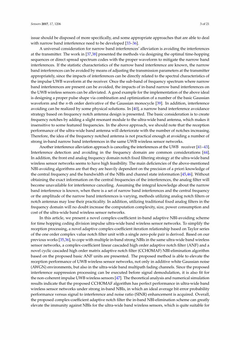
The detailed implementation of the one order complex-coefficient adaptive notch filter unitwith a single constrained zero-pole pair is depicted in Figure 2. Once the frequency angle χ1(n)has converged to the objective central frequency of NBI, the adaptive notch filter unit will cut offthe corresponding in-band strong NBI component. In this place, we define the error function e1(n) as:
e1(n) = x1(n)− h1(n)x1(n− 1) + ρh1(n)y1(n− 1). (29)
According to adaptive filter theory, the objection is to minimize the mean square error (MSE) ofe1(n); hence, the cost function becomes:
C1(n) = E| e1(n) |2 ≈1N
N
∑n=1e1(n)e∗1(n), (30)
where * denotes the complex conjugate.
1( )x n
1( )y n1
z
1( )h n
Adaptive Iteration
1( )h n
Figure 2. Implementation of the one order complex-coefficient notch filter unit with a single constrainedzero-pole pair.
The adaptive weight coefficient of the one-order adaptive notch filter with a single zero-pole pairis determined by minimizing the cost function C1(n). Thus, the iteration relationship can be consideredas the gradient of C1(n) with the instantaneous angular frequency χ1(n), which can be given by:
∇C1(n)∇χ1(n)
= jx1(n)x∗1(n− 1)exp−jχ1(n) − jx∗1(n)x1(n− 1)expjχ1(n)
+jρx∗1(n)y1(n− 1)expjχ1(n) − jρx1(n)y∗1(n− 1)exp−jχ1(n). (31)
We denote T1(n) = x1(n)x∗1(n − 1)exp−jχ1(n) + ρx∗1(n)y1(n − 1)expjχ1(n); thus, thefollowing one-step adaptive frequency angle iteration relationship can be obtained:
χ1(n+1) = χ1(n) + µImag[T1(n)], (32)
where µ denotes the adaptive step-size associated with the convergence rate of the proposed ANF andImag denotes taking the imaginary part of the complex variabled.
From (32), the following iteration relationship can be obtained:
expjχ1(n+1) = expjχ1(n) · expjµImag[T1(n)]. (33)

Sensors 2017, 17, 1206 11 of 21
Expending (33) with the second order Taylor series expansion yields:
expjχ1(n+1)=expjχ1(n)1+ jµImag[T1(n)]+12!jµImag[T1(n)]2 +ojµImag[T1(n)]2, (34)
where a function f (x) is o(g(x)) if limx→0 f (x)/g(x) = 0. Substituting h1(n) = expjχ1(n) into (34),we obtain the iteration relationship of adaptive weight coefficient as:
h1(n+1) = h1(n)1 + jµImag[T1(n)]−12µImag[T1(n)]2. (35)
To clarify the proposed adaptive weight coefficient iteration algorithm, we summarizethe procedure of the above-mentioned complex-coefficient ANF unit with a single zero-pole pairin Table 1.
Table 1. The detailed procedure of the one order complex-coefficient notch filter unit with a singleconstrained zero-pole pair.
Step 1 initialize system variables x1(0) = 0.1, y1(0) = 0.1,
set initial value h1(1) = 1;Step 2 for n = 1, 2, 3..., calculate the intermediate variables according to
T1(n) = x1(n)x∗1(n− 1)h∗1(n) + ρx∗1(n)y1(n− 1)h1(n) ;Step 3 for n = 1, 2, 3..., calculate the complex coefficient according to
h1(n+1)=h1(n)1+ jµImag[T1(n)]− 12µImag[T1(n)]2 ;
Step 4 calculate the output of the adaptive notch filter unit according toy1(n) = x1(n)− h1(n)x1(n− 1) + ρh1(n)y1(n− 1),and then turn back to Step 2.
4.2. Linear Cascaded High Order Complex-Coefficient Adaptive Notch Filter
For the multiple in-band strong NBI case, it is inevitable to utilize high-order ANF. If we directlyexpand the numerator polynomial into the high-order finite impulse response (FIR) filter and adjustthe denominator polynomial at the same time, it is rather hard to guarantee all of the pole pointsdistribute inside the unit circle to satisfy stability.
A feasible approach is to cascade the proposed one order complex efficient IIR ANF units intolinear cascaded (LC) high order ANF [36]. The implementation of the linear cascaded high ordercomplex-coefficient ANF is depicted in Figure 3. The transfer function of K-order linear cascadedcomplex efficient ANF becomes:
H(z) =K
∏k=1
Hk(z) =K
∏k=1
1− hkz−1
1− ρhkz−1 , (36)
where Hk(z) denotes the transfer function of the k-th basic IIR notch filter unit and hk denotes the k-thadaptive weight coefficient. The frequency response of the above transfer function has a unified gainat all frequencies; except at the notch frequencies in the present of narrow band interferences, theirgains approximate to zero.

Sensors 2017, 17, 1206 12 of 21
1( )kx n 1
z
1( )kh n
Adaptive IterationAdaptive Iteration
1( )kh n
( )ky n
1
z
( )kh n
Adaptive IterationAdaptive Iteration
( )kh n
Cell k-1 Cell k
1( )ky n
Figure 3. Implementation of linear cascaded complex-coefficient high order adaptive notch filter.
In the LC high order complex-coefficient ANF framework, the output of the (k−1)-th oneorder ANF unit can be considered as the input of the k-th complex-coefficient one order ANF unit,so the difference equation of the k-th section is given by:
yk(n) = yk−1(n)− hk(n)yk−1(n− 1) + ρhk(n)yk(n− 1). (37)
Thus, the intermediate variable of the k-th one order complex-coefficient ANF unit becomes:
Tk(n) = yk−1(n)y∗k−1(n− 1)h∗k (n) + ρy∗k−1(n)yk(n− 1)hk(n). (38)
The complex coefficients’ iteration relationship for the k-th one order complex-coefficient IIR ANFunit can be expressed as:
hk(n+1) = hk(n)1 + jµImag[Tk(n)]−12µImag[Tk(n)]2. (39)
In the LC K-order complex-coefficient ANF, the adaptive iteration relationship of each one orderANF unit can be updated separately, since the objection frequency of NBI in each ANF unit is different.The processing of the LC high order complex-coefficient ANF algorithm based on one order ANF unitcan be found in Table 2.
Table 2. The procedure of the linear cascaded high order complex-coefficient adaptive notch filteralgorithm based on the basic one order adaptive notch filter unit.
Step 1 initialize system variables x1(0) = 0.1, y1(0) = 0.1, yk(0) = 0.1,set initial value hk(1) = 1, for k = 1, 2..., K;
Step 2 for n = 1, 2, 3..., calculate the intermediate variable according toTk(n) = yk−1(n)y∗k−1(n− 1)h∗k (n) + ρy∗k−1(n)yk(n− 1)hk(n);
Step 3 for n = 1, 2, 3..., calculate the adaptive instantaneous complex weight coefficients according to
hk(n+1)=hk(n)1+ jµImag[Tk(n)]− 12µImag[Tk(n)]2 ;
Step 4 calculate the output of the adaptive notch filter unit according toyk(n) = yk−1(n)− hk(n)yk−1(n− 1) + ρhk(n)yk(n− 1)and then turn back to Step 2.

Sensors 2017, 17, 1206 13 of 21
4.3. Cyclic Cascaded High Order Complex-Coefficient Matrix Adaptive Notch Filter
In the linear cascaded high order complex-coefficient adaptive notch filter, the trackingperformance will degrade, since the input of the current section of the adaptive notch filter unitis the output of the previous one. Moreover, the convergence rate will decrease. To overcome the aboveshortcomings, we propose a cyclic cascaded framework, which is depicted in Figure 4. A K-order cycliccascaded matrix adaptive notch filter is composed of the K× K basic one order IIR notch filter units.Apparently, K × K adaptive coefficients should be calculated for each iteration in a K-order cycliccascaded high order matrix adaptive notch filter. In fact, only K active adaptive weight coefficientsin the left column as depicted under the solid line in Figure 4 should be determined according to theweight coefficient iteration algorithm. Meanwhile, the updated complex value weight coefficientsare copied to the other corresponding adaptive notch filter units at each iteration, which reduced thealgorithm complexity greatly. For a k order CCHOMANF, only 12k multipliers and 5k adders are usedto fulfil the update of the adaptive weight coefficients. Commonly, the number of in-band narrowband interferences with different central frequencies is not more than 10 in practical ultra-wide bandwireless sensor networks. In other words, the order of CCHOMANF is not very large, so we can set3 ≤ k < 10, which makes the computation complexity of the proposed narrow band interferencesuppression algorithm reasonable.
2NF
3NF
NFK
1NF
2NF
1,1( )y n
1NF
1NFK
NFK
1
K( )x n
( )y n
NFK 1NF1NFK
1NFK NFK
2NFK
2NFK 3NFK
2,1( )y n
1,1( )Ky n
,1( )Ky n
1, ( )Ky n
2, ( )Ky n
1, ( )K Ky n
, ( )K Ky n
1, 1( )Ky n
2, 1( )Ky n
1, 1( )K Ky n
, 1( )K Ky n
Figure 4. The framework of cyclic cascaded high order complex-coefficient matrix adaptive notch filterbased on one order complex-coefficient adaptive notch filter units.
To simplify the discussion, we define adaptive notch filter cell NFk (k = 1, 2, ..., K) as the k-th activebasic adaptive notch filter unit, which is depicted in left column in Figure 4. The transfer function ofthe k-th active adaptive notch filter is given by:
Hk(z) =1− hkz−1
1− ρhkz−1 . (40)
Hence, the transfer function of cyclic cascaded high order matrix adaptive notch filter canbe described as:
H(z) =1K
K
∑m=1
K
∏k=1
Hk(z), (41)

Sensors 2017, 17, 1206 14 of 21
where Hk(z) designates the k-th one order complex-coefficient IIR adaptive notch filter unit.The normalized frequency response of K order CCHOMANF is depicted in Figure 5. In theory,
a K order CCHOMANF can suppress K narrow band interferences. Substantially, in the cyclic cascadedhigh order matrix adaptive notch filter, the entire complex plane is divided into K circulator sectionswith each section being monitored by a basic one-order adaptive notch filter unit. The specific numberof cascaded units is dependent on the practical application situation. In this place, we note that theorder number K of CCHOMANF does not need to be adjusted in different application scenarios, evenif the number of narrow band interferences is variable. Normally, we consider 5≤K≤10 (let the ordernumber K be lager than the number of narrow band interferences in different frequencies). When Kis more than the number of narrow band interferences NNBIs, K−NNBIs redundant adaptive notch filterunits will present. The redundant complex-coefficient adaptive notch filter cells will vibrate around thecentral frequencies of narrow band interferences close to them. Therefore, the proposed CCHOMANFstill runs soundly, even though the order of the CCHOMANF K is not equal to the number ofnarrow band interferences. It is worth noting that, in the initialization stage, we set hk(1) as follows:h1(1) = 1, h2(1) = cos(2π/K) + jsin(2π/K), hk(1) = cos(2(k− 1)π/K) + jsin(2(k− 1)π/K), whichguarantees that different adaptive notch filter units converge to different narrow band interferencesclose to them, rather than some certain narrow band interference.
0
Norm
aliz
ed F
requen
cy R
esponse
Normalized Frequency Angle
( )H z
1arg h 2arg h arg Kh
Figure 5. Normalized frequency response of the K order complex-coefficient cyclic cascaded matrixadaptive notch filter.
Through the aforementioned construction, the cyclic cascaded high order adaptive notch filterhas the following excellent properties: (1) all of the weight coefficients are sought simultaneously asdepicted in the left column in Figure 4, alleviating the associated polynomial deflation; (2) a prioriinformation or constraints on the zero-pole locations are easily incorporated into the estimationprocedure; (3) the iterations utilizing the gradient-descent algorithm have been proven to be relativelyeffective with a minimum computational complexity; and (4) the imperfect knowledge of the practicalultra-wide band channel has tiny effects on the proposed narrow band interferences suppression sincethe interference components will be cleaned off rather than be recovered.
5. Numerical Simulation Results and Reception Performance Analysis
In this section, the numerical simulation results are presented to illustrate the receptionperformance of time hopping pulse position modulation impulse-based ultra-wide band wirelesssensors and the performance enhancement provided by the complex-coefficient adaptive notch filternarrow band interference suppression algorithm developed in this paper under different channelpropagation environments. We consider a second derivative of the Gaussian monocycle transmittedimpulse waveform with τp = 0.0625 ns. The frame length Tf = 512 ns; the duration of the chipTc = 0.25 ns; the number of time slots per frame is 2048; the number of transmitted base band pulses

Sensors 2017, 17, 1206 15 of 21
per symbol Ns = 4; and the number of active users Nu = 8. We suppose the time hopping codes fordifferent users are orthogonal.
SNR (dB)0 2 4 6 8 10 12 14 16 18 20
Ave
rage
Bit
Err
or P
roba
bilit
y
10-5
10-4
10-3
10-2
10-1
100
No NBIISR=5dBISR=10dBISR=15dBISR=20dBISR=25dB
Figure 6. Average bit error probability of the TH-pulse position modulation (PPM) UWB wirelesssensors in the unfaded scenario with the narrow band interferences under different power levels.
We first observe the reception performance of the time hopping pulse position modulation impulseultra-wide band signal in the present of narrow band interferences under additive white Gaussiannoise (unfaded scenario) channel. Figure 6 shows the simulated average bit error probability (BEP)versus average signal to noise ratio (SNR) for different values of the narrow band interference to signalratio (ISR). We can find that the narrow band interference will deteriorate the system performance,especially when the ISR is more than 10 dB.
Time (ns)0 20 40 60 80 100 120 140 160 180 200
Nor
mal
ized
Impu
lse
resp
onse
0
0.1
0.2
0.3
0.4
0.5
0.6
0.7
0.8
0.9
1
Figure 7. Normalized impulse response of the IEEE 802.15.4a CM1 channel model for the indoorresidential line of sight scenario.
Sensors 2017, 17, 1206 16 of 21
SNR (dB)0 5 10 15 20 25
Ave
rage
Bit
Err
or P
roba
bilit
y
10-5
10-4
10-3
10-2
10-1
100
No NBIISR=5dBISR=10dBISR=15dBISR=20dBISR=25dB
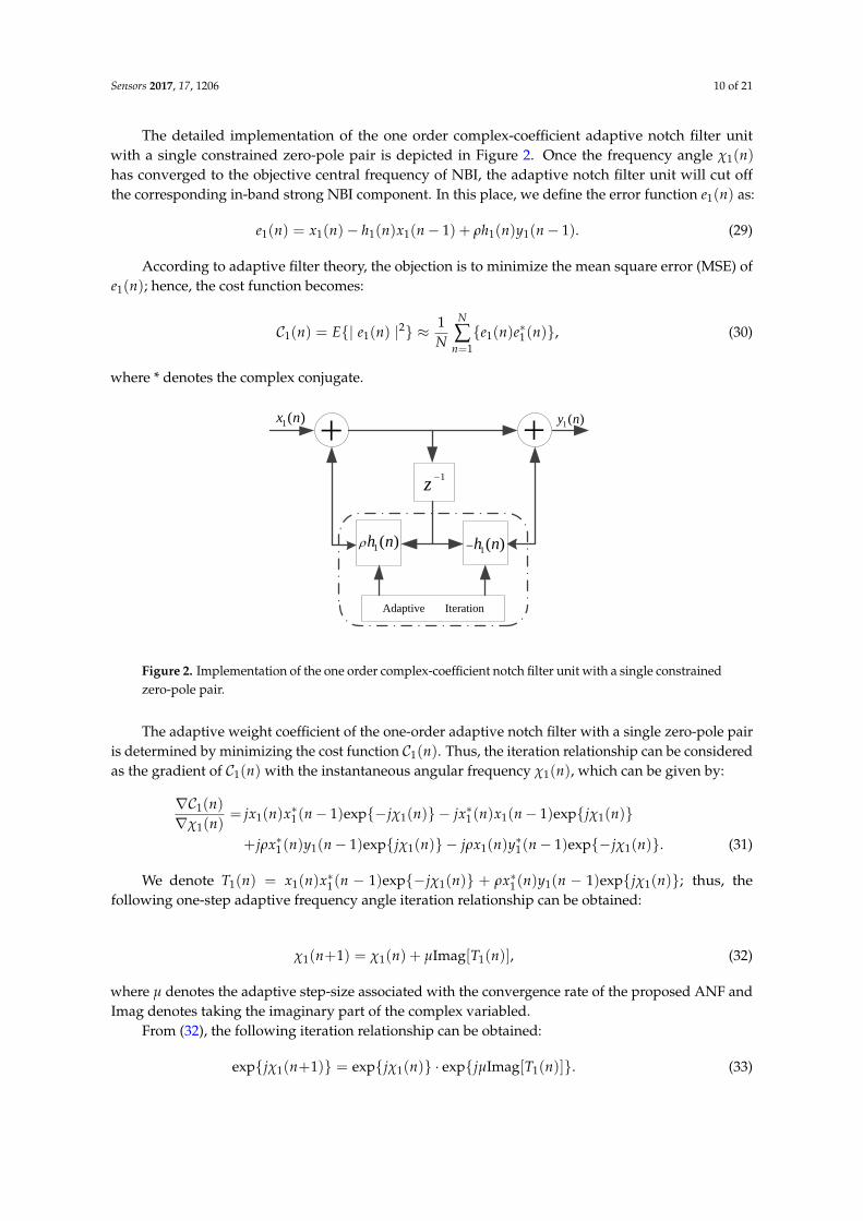
Figure 8. Average bit error probability for the TH-PPM UWB wireless sensors with narrow bandinterferences under the IEEE 802.15.4a CM1 multipath fading channel.
The practical ultra-wide band radio propagation environment is a dense multipath fading channel.A number of UWB channel models have been proposed in the last decade: [58] suggested a modelfor the frequency range below 1 GHz. The IEEE 802.15.3a group developed a channel model thatis valid from 3 GHz to 10 GHz, but is designed only for indoor residential and office environments,and the distance between transmitter and receiver is restricted to 10 m [59]. The IEEE 802.15.3a channelmodel is parameterized for line of sight (LOS), as well as non-line of sight (NLOS) circumstancesin residential, industrial, office, farm and open outdoor environments. Based on more practicalmeasurements than the IEEE 802.15.3a channel model, the IEEE 802.15.4a work groups provided a moregeneral parameterized ultra-wide band channel model from 2 GHz to 10 GHz. The standard ultra-wideband channel model also covers office, farm, residential, industrial, open outdoor environments andbody-area networks with both LOS and NLOS cases [50,60]. In this place, we first consider theIEEE 802.15.4a CM1 channel model for the indoor residential environment under the line of sightcase. The normalized impulse response in the IEEE 802.15.4a CM1 channel model is depicted inFigure 7. The impulse response of the ultra-wide band CM1 channel consists of hundreds of resolvablemulti-path components. It is not difficult to notice that the channel impulse response of CM1 is thesum of attenuated, delayed and distorted multipath components, and in this case, well-known Rakereceivers can be used to collect the dispersive energy of multipath components. A Rake receivercan consist of a matched filter with a tapped delay line matching the impulse response of the practicalultra-wide band channel. It also can be replaced by a set of time delay correlators that are sampled atthe delays related to specific multipath components.
We next consider the case in which the time hopping ultra-wide band wireless signal undergoesmultipath fading. More specifically, the IEEE 802.15.4a CM1 channel model for the indoor residentialenvironment under line of sight case is considered. In the simulations, selective Rake combiningis employed, where the number of fingers Lr is chosen big enough. The results are averagedover 1000 channel realizations, each associated with a random TH code. It can be seen fromFigure 8 that the performance is severely degraded by the presence of fading on the desired signalcomparing the average bit error probability with the previous scenarios. When the ISR is more than20 dB, the system performance is unsatisfactory if no proper narrow band interference suppression
Sensors 2017, 17, 1206 17 of 21
is employed. The proposed interference suppression algorithm can greatly improve the receptionperformance under the strong in-band interferences case.
Time (ns)0 20 40 60 80 100 120 140 160 180 200
Nor
mal
ized
Impu
lse
resp
onse
0
0.1
0.2
0.3
0.4
0.5
0.6
0.7
0.8
0.9
1
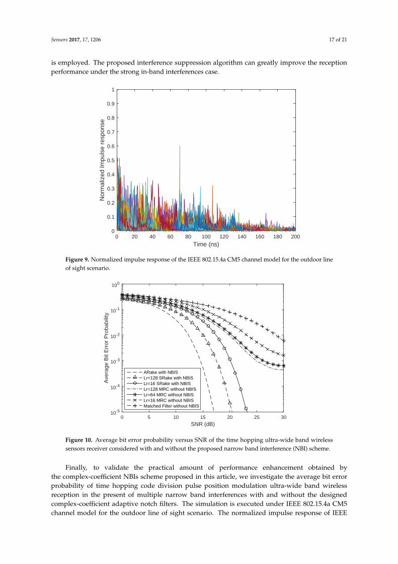
Figure 9. Normalized impulse response of the IEEE 802.15.4a CM5 channel model for the outdoor lineof sight scenario.
SNR (dB)0 5 10 15 20 25 30
Ave
rage
Bit
Err
or P
roba
bilit
y
10-5
10-4
10-3
10-2
10-1
100
ARake with NBISLr=128 SRake with NBISLr=16 SRake with NBISLr=128 MRC without NBISLr=64 MRC without NBISLr=16 MRC without NBISMatched Filter without NBIS
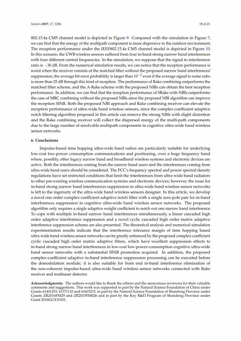
Figure 10. Average bit error probability versus SNR of the time hopping ultra-wide band wirelesssensors receiver considered with and without the proposed narrow band interference (NBI) scheme.
Finally, to validate the practical amount of performance enhancement obtained bythe complex-coefficient NBIs scheme proposed in this article, we investigate the average bit errorprobability of time hopping code division pulse position modulation ultra-wide band wirelessreception in the present of multiple narrow band interferences with and without the designedcomplex-coefficient adaptive notch filters. The simulation is executed under IEEE 802.15.4a CM5channel model for the outdoor line of sight scenario. The normalized impulse response of IEEE
Sensors 2017, 17, 1206 18 of 21
802.15.4a CM5 channel model is depicted in Figure 9. Compared with the simulation in Figure 7,we can find that the energy of the multipath component is more dispersive in the outdoor environment.The reception performance under the IEEE802.15.4a CM5 channel model is depicted in Figure 10.In this scenario, the UWB wireless sensors suffered from four in-band strong narrow band interferenceswith four different central frequencies. In the simulation, we suppose that the signal to interferenceratio is −30 dB. From the numerical simulation results, we can notice that the reception performance isworst when the receiver consists of the matched filter without the proposed narrow band interferences’suppression; the average bit error probability is larger than 10−2 even if the average signal to noise ratiois more than 25 dB through this kind of reception. The performance of Rake combining outperforms thematched filter scheme, and the A-Rake scheme with the proposed NBIs can obtain the best receptionperformance. In addition, we can find that the reception performance of SRake with NBIs outperformsthe case of MRC combining without the proposed NBIs since the proposed NBI algorithm can improvethe reception SINR. Both the proposed NBI approach and Rake combining receiver can elevate thereception performance of ultra-wide band wireless sensors, since the complex-coefficient adaptivenotch filtering algorithm proposed in this article can remove the strong NBIs with slight distortionand the Rake combining receiver will collect the dispersed energy of the multi-path componentsdue to the large number of resolvable multipath components in cognitive ultra-wide band wirelesssensor networks.
6. Conclusions
Impulse-based time hopping ultra-wide band radios are particularly suitable for underlyinglow-cost low-power consumption communications and positioning, over a huge frequency bandwhere, possibly, other legacy narrow band and broadband wireless systems and electronic devices areactive. Both the interferences coming from the narrow band users and the interferences coming fromultra-wide band users should be considered. The FCC’s frequency spectral and power spectral densityregulations have set restricted conditions that limit the interferences from ultra-wide band radiatorsto other pre-existing wireless communication systems and electronic devices; however, the issue forin-band strong narrow band interferences suppression in ultra-wide band wireless sensor networksis left to the ingenuity of the ultra-wide band wireless sensors designer. In this article, we developa novel one order complex-coefficient adaptive notch filter with a single zero-pole pair for in-bandinterferences suppression in cognitive ultra-wide band wireless sensor networks. The proposedalgorithm only requires a single adaptive weight coefficient to notch out one narrow band interference.To cope with multiple in-band narrow band interferences simultaneously, a linear cascaded highorder adaptive interference suppression and a novel cyclic cascaded high order matrix adaptiveinterference suppression scheme are also presented. The theoretical analysis and numerical simulationexperimentation results indicate that the interference tolerance margin of time hopping basedultra-wide band wireless sensor networks can be greatly enhanced by the proposed complex-coefficientcyclic cascaded high order matrix adaptive filters, which have excellent suppression effects toin-band strong narrow band interferences in low-cost low-power-consumption cognitive ultra-wideband sensor networks with a substantial SINR promotion acquired. In addition, the proposedcomplex-coefficient adaptive in-band interference suppression processing can be executed beforethe demodulation module; it is also suitable for front end in-band interference elimination ofthe non-coherent impulse-based ultra-wide band wireless sensor networks connected with Rakereceiver and multiuser detector.
Acknowledgments: The authors would like to thank the editors and the anonymous reviewers for their valuablecomments and suggestions. This work was supported in part by the Natural Science Foundation of China underGrants 61401253, 61371110 and 61603215, in part by the Natural Science Foundation of Shandong Province underGrants ZR2016FM29 and ZR2015FM026 and in part by the Key R&D Program of Shandong Province underGrant 2016GGX10101.

Sensors 2017, 17, 1206 19 of 21
Author Contributions: Hailiang Xiong and Wensheng Zhang conceived and designed the experiments; Hongji Xuperformed the experiments; Zhengfeng Du and Huaibin Tang analyzed the data; Jing Li contributed analysis toolsand numerical simulations; Hailiang Xiong wrote the article; Wensheng Zhang revised the article.
Conflicts of Interest: The authors declare no conflict of interest.
References
1. Sherman, M.; Mody, A.N.; Martinez, R.; Rodriguez, C.; Reddy, R. Standards Supporting Cognitive Radioand Networks, Dynamic Spectrum Access, and Coexistence. IEEE Commun. Mag. 2008, 46, 72–79.
2. Haykin, S. Cognitive Radio: Brain-Empowered Wireless Communications. IEEE J. Sel. Areas Commun. 2005,23, 201–220.
3. Zabini, F.; Conti, A. Inhomogeneous Poisson Sampling of Finite-Energy Signals with Uncertainties in Rd.IEEE Trans. Signal Process. 2016, 64, 4679–4694.
4. Xiao, Z.; Liu, H.; Vincent, H.; Li, T.; Wang, D. Analytical Study on Multi-Tier 5G Heterogeneous Small CellNetworks: Coverage Performance and Energy Efficiency. Sensors 2016, 16, 1854.
5. Huseyin, A.; Sahin Mustafa, E. Narrowband Interference Issues in Ultra Wideband Systems. Ultra WidebandWirel. Commun. 2006, 255–275, doi:10.1002/9780470042397.ch11.
6. Sithamparanathan, K.; Giorgetti, A. Cognitive Radio Techniques: Spectrum Sensing, Interference Mitigation,and Localization; Artech House: Norwood, MA, USA, 2012.
7. Thirumalaivasan, K.; Nakkeeran, R.; Oudaya Coumar, S. Effective Notch Ultra-Wideband Filter UsingRing Resonator for the Rejection of IEEE 802.11a. In Proceedings of the 2nd International Conference onComputing, Communication and Networking Technology, Karur, India, 29–31 July 2010; pp. 1–4.
8. Win, M.Z.; Scholtz, R.A. Impulse Radio: How it Works. IEEE Commun. Lett. 1998, 2, 36–38.9. Scholtz, R.A. Multiple Access with Time-Hopping Impulse Modulation. In Proceedings of the 1993 IEEE
Miltary Communications Conference (MILCOM), Los Angeles, CA, USA, 10–12 November 1993, pp. 447–450.10. Fontana, R.J. Recent System Applications of Short-Pulse Ultra-Wideband (UWB) Technology. IEEE Trans.
Microw. Theory Tech. 2004, 52, 2087–2104.11. Xiong, H.; Cheng, J. Investigation of Short-Range High Precision 3D Localization Via UWB Radio.
In Proceedings of the 2014 IEEE Global Communications Conference (GLOBECOM), Austin, TX, USA,8–12 December 2014.
12. Yang, L.Q.; Giannakis, G.B. Ultra-Wideband Communications: An Idea Whose Time Has Come. IEEE SignalProcess Mag. 2004, 21, 26–54.
13. Martin, K.J. Ferderal Communications Commission (FCC): Ultra-Wideband Transmission Communications;Ferderal Communications Commission First Report and Order; FCC: Washington, DC, USA, 2002; pp. 98–153.
14. Chiani, M.; Giorgetti, A. Coexistence between UWB and Narrow-Band Wireless Communication Systems.Proc. IEEE 2009, 97, 231–254.
15. Win, M.Z.; Dardari, D.; Molisch, A.F.; Wiesbeck, W.; Zhang, J.Y. History and Applications of UWB. Proc. IEEE2009, 97, 198–204.
16. Giorgetti, A.; Chiani, M.; Win, M.Z. The Effect of Narrowband Interference on Wideband WirelessCommunication Systems. IEEE Trans. Commun. 2005, 53, 2139–2149.
17. Da Silva, C.R.C.M.; Milstein, L.B. The Effects of Narrowband Interference on UWB Communication Systemswith Imperfect Channel Estimation. IEEE J. Sel. Areas Commun. 2006, 24, 717–723.
18. Win, M.Z.; Pinto, P.C.; Shepp, L. A Mathematical Theory of Network Interference and Its Applications.Proc. IEEE 2009, 97, 205–230.
19. Conti, A.; Panchenko, D.; Sidenko, S.; Tralli, V. Log-Concavity Property of the Error Probability withApplication to Local Bounds for Wireless Communications. IEEE Trans. Inf. Theory 2009, 55, 2766–2775.
20. Rabbachin, A.; Quek, T.Q.S.; Shin, H.; Win, M.Z. Cognitive Network Interference. IEEE J. Sel. Areas Commun.2011, 29, 480–493.
21. McEliece, R.; Stark, W. Channels with Block Interference. IEEE Trans. Inf. Theory 1984, 30, 44–53.22. Chiani, M.; Conti, A.; Andrisano, O. Outage Evaluation for Slow Frequency-Hopping Mobile Radio Systems.
IEEE Trans. Commun. 1999, 47, 1865–1874.23. Conti, A.; Masini, B.; Zabini, F.; Andrisano, O. On the Down-Link Performance of Multi-Carrier CDMA
Systems with Partial Equalization. IEEE Trans. Wirel. Commun. 2007, 6, 230–239.

Sensors 2017, 17, 1206 20 of 21
24. Shi, K.; Zhou, Y.; Kelleci, B.; Fischer, T.W.; Serpedin, E.; Karsilayan, A.I. Impacts of Narrowband Interferenceon OFDM-UWB Receivers: Analysis and Mitigation. IEEE Trans. Signal Process. 2007, 55, 1118–1128.
25. Lehmann, N.H.; Haimovich, A.M. The Power Spectral Density of a Time Hopping UWB Signal: A Survey.In Proceedings of the 2003 IEEE Conference on Ultra Wideband Systems and Technologies, Reston, VA, USA,16–19 November 2003; pp. 234–239.
26. Hamalainen, M.; Hovinen, V.; Tesi, R.; Iinatti, J.H.J.; Latva-aho, M. On the UWB System Coexistence withGSM900, UMTS/WCDMA, and GPS. IEEE J. Sel. Areas Commun. 2002, 20, 1712–1721.
27. Chu, X.L.; Murch, R.D. The Effect of NBI on UWB Time-Hopping Systems. IEEE Trans. Wirel. Commun. 2004,3, 1431–1436.
28. Akyildiz, I.F.; Su, W.; Sankarasubramaniam, Y.; Cayirci, E. A Survey on Sensor Networks. IEEE Commun. Mag.2002, 40, 102–114.
29. Tubaishat, M.; Madria, S. Sensor Networks: An Overview. IEEE Potentials 2003, 22, 20–23.30. Dardari, D.; Conti, A.; Buratti, C.; Verdone, R. Mathematical Evaluation of Environmental Monitoring
Estimation Error Through Energy-Efficient Wireless Sensor Networks. IEEE Trans. Mob. Comput. 2007,6, 790–802.
31. Estrin, D.; Girod, L.; Pottie, G.; Srivastava, M. Instrumenting the World with Wireless Sensor Networks.In Proceedings of the 2001 IEEE International Conference on Acoustics, Speech, and Signal Processing,Salt Lake City, UT, USA, 7–11 May 2001; Volume 4, 2033–2036.
32. Wu, X.; Yang, Z. Coding Versus Spreading for Narrowband Interference Suppression. IEEE Trans. Veh. Technol.2016, 65, 2129–2141.
33. Somayazulu, V.S.; Foerster, J.R.; Roy, S. Design Challenges for Very High Data Rate UWB Systems.In Proceedings of the 36th Asilomar Conference on Signals, Systems and Computers, Pacific Grove, CA,USA, 3–6 November 2002; Volume 1, pp. 717–721.
34. Kikuta, K.; Hirose, A. Narrowband Interference Mitigation in UWB Systems Utilizing Frequency Dependenceof Null Formation in Array Antennas. IEEE Access 2017, 4, 8715–8720.
35. Xiong, H.; Zhang, W.; Du, Z.; He, B.; Yuan, D. Front-End Narrowband Interference Mitigation for DS-UWBReceiver. IEEE Trans. Wirel. Commun. 2013, 12, 4328–4337.
36. Xiong, H. An Efficient Narrowband Interference Suppression Approach in Ultra Wide Band Receiver.IEEE Sens. J. 2017, 17, 2741–2748.
37. Shao, H.; Beaulieu, N.C. Direct Sequence and Time-Hopping Sequence Designs for Narrowband InterferenceMitigation in Impulse Radio UWB Systems. IEEE Trans. Commun. 2011, 59, 1957–1965.
38. Giorgetti, A. Interference Mitigation Technique by Sequence Design in UWB Cognitive Radio. In Proceedingsof the 3rd International Symposium on Applied Sciences in Biomedical and Communication Technologies,Rome, Italy, 7–10 November 2010; pp. 1–5.
39. Wu, X.; Tian, Z.; Davidson, T.N.; Giannakis, G.B. Optimal Waveform Design for UWB Radios. IEEE Trans.Signal Process. 2006, 54, 2009–2021.
40. Schantz, H.G.; Wolenec, G.; Myszka, E.M. Frequency Notched UWB Antennas. In Proceedings of the 2003IEEE Conference on Ultra Wideband Systems and Technologies, Reston, VA, USA, 16–19 November 2003;pp. 214–218.
41. Wu, Z.Z.; Shim, Y.; Rais-Zadeh, M. Miniaturized UWB Filters Integrated with Tunable Notch Filters Usinga Silicon-Based Integrated Passive Device Technology. IEEE Trans. Microw. Theory Tech. 2012, 60, 518–527.
42. Song, K.J.; Xue, Y. Compact Ultra-Wideband (UWB) Bandpass Filters with Multiple Notched Bands.IEEE Microw. Wirel. Compon. Lett. 2010, 20, 447–449.
43. Ghatak, R.; Sarkar, P.; Mishra, R.K.; Poddar, D.R. A Compact UWB Bandpass Filter with Embedded SIR asBand Notch Structure. IEEE Microw. Wirel. Compon. Lett. 2011, 21, 261–263.
44. Mariani, A.; Giorgetti, A.; Chiani, M. Wideband Spectrum Sensing by Model Order Selection. IEEE Trans.Wirel. Commun. 2015, 14, 6710–6721.
45. Chen, X.H.; Zhang, L.J.; Peng, Y.T. UWB Bandpass Filter with Sharp Rejection and Narrow Notched Band.Electron. Lett. 2014, 50, 1077–1079.
46. Luo, X.; Ma, J.G.; Seng, K.Y.; Li, E.P. Compact Ultra-Wideband (UWB) Bandpass Filter with Ultra-NarrowDual- and Quad-Notched Bands. IEEE Trans. Microw. Theory Tech. 2011, 59, 1509–1519.
47. Decarli, N.; Giorgetti, A.; Dardari, D.; Chiani, M.; Win, M.Z. Stop-and-Go Receivers for Non-CoherentImpulse Communications. IEEE Trans. Wirel. Commun. 2014, 13, 4821–4835.

Sensors 2017, 17, 1206 21 of 21
48. Win, M.Z.; Scholtz, R.A. Ultra-Wide Bandwidth Time-Hopping Spread-Spectrum Impulse Radio for WirelessMultiple-Access Communications. IEEE Trans. Commun. 2000, 48, 679–689.
49. Gezici, S.; Molisch, A.F.; Poor, H.V.; Kobayashi, H. The Tradeoff between Processing Gains of an ImpulseRadio UWB System in the Presence of Timing Jitter. IEEE Signal Commun. 2007, 55, 1504–1515.
50. Molisch, A.F.; Balakrishnan, K.; Cassioli, D.; Chong, C.; Emami, S.; Fort, A.; Karedal, J.; Kunisch, J.;Schantz, H.; Schuster, U.; et al. IEEE 802.15.4a Channel Model-Final Report; The Institute of Electrical andElectronics Engineers Report, TG4a; IEEE 802.15.4 Task Group: New York, NY, USA, 2004; pp. 1–48.
51. Cassioli, D.; Win, M.Z.; Vatalaro, F.; Molisch, A.F. Low Complexity Rake Receivers in Ultra-WidebandChannels. IEEE Trans. Wirel. Commun. 2007, 6, 1265–1275.
52. Karapistoli, E.; Pavlidou, F.N.; Gragopoulos, I.; Tsetsinas, I. An Overview of the IEEE 802.15.4a Standard.IEEE Commun. Mag. 2010, 48, 47–53.
53. Pinto, P.C.; Giorgetti, A.; Win, M.Z.; Chiani, M. A Stochastic Geometry Approach to Coexistencein Heterogeneous Wireless Networks. IEEE J. Sel. Areas Commun. 2009, 27, 1268–1282.
54. Win, M.Z.; Chrisikos, G.; Sollenberger, N.R. Performance of Rake Reception in Dense Multipath Channels:Implications of Spreading Bandwidth and Selection Diversity Order. IEEE J. Sel. Areas Commun. 2000,18, 1516–1525.
55. Conti, A.; Gifford, W.M.; Win, M.Z.; Chiani, M. Optimized Simple Bounds for Diversity Systems.IEEE Trans. Commun. 2009, 57, 2674–2685.
56. Chu, X.; Murch, R.; Liu, J.; Ghavami, M. Pilot-Channel-Assisted Log-Likelihood-Ratio Selective RakeCombining for Low-Rate Ultra-Wideband Communications. IEEE Trans. Commun. 2008, 56, 1313–1323.
57. Martret, C.J.L.; Giannakis, G.B. All-Digital Impulse Radio with Multiuser Detection for Wireless CellularSystems. IEEE Trans. Commun. 2002, 50, 1440–1450.
58. Cassioli, D.; Win, M.Z.; Molisch, A.F. The Ultra-Wide Bandwidth Indoor Channel—From Statistical Modelto Simulations. IEEE J. Sel. Areas Commun. 2002, 20, 1247–1257.
59. Molisch, A.F.; Cassioli, D.; Chong, C.C.; Emami, S.; Fort, A.; Kannan, B.; Karedal, J.; Kunisch, J.; Schantz, H.G.;Siwiak, K.; et al. A Comprehensive Standardized Model for Ultrawideband Propagation Channels.IEEE Trans. Antennas Propag. 2006, 54, 3151–3166.
60. Doucet, A.; Wang, X.D. Monte Carlo Methods for Signal Processing: A Review in the Statistical SignalProcessing Context. IEEE Signal Process. Mag. 2005, 22, 152–170.
c© 2017 by the authors. Licensee MDPI, Basel, Switzerland. This article is an open accessarticle distributed under the terms and conditions of the Creative Commons Attribution(CC BY) license (http://creativecommons.org/licenses/by/4.0/).