a novel separated position and orientation system
TRANSCRIPT

Research ArticleA Novel Separated Position and Orientation System Integratedwith Inertially Stabilized Platform
Yanshun Zhang 1 Shuangji Feng 1 ZhanqingWang 2
Xiaopeng Xi 34 andMing Li 1
1School of Instrumentation and Optoelectronic Engineering Beihang University Beijing 100191 China2School of Automation Beijing Institute of Technology Beijing 100081 China3Tianjin Zhong Wei Aerospace Data System Technology Co Ltd Tianjin 300301 China4Tianjin Key Laboratory of Intelligent Information Processing in Remote Sensing Tianjin 300100 China
Correspondence should be addressed to Shuangji Feng qidaifsj6buaaeducn
Received 21 June 2017 Accepted 15 January 2018 Published 15 February 2018
Academic Editor Sebastien Poncet
Copyright copy 2018 Yanshun Zhang et alThis is an open access article distributed under the Creative Commons Attribution Licensewhich permits unrestricted use distribution and reproduction in any medium provided the original work is properly cited
Considering the application requirements of independent imaging payloads design a novel scheme of separated position andorientation system (POS) is proposed in which the high-precision inertial sensors of traditional centralized POS fixed on theimaging payloads are mounted on three gimbals of the inertially stabilized platform (ISP) respectively and make them integratedThen the kinematics model of the ISP system is built to transmit the inertial information measured by separated inertial sensorsmounted on ISP gimbals and flight body to the imaging payloads calculating the position and attitude of the imaging payloads toachieve the function of separated POS Based on the model a series of simulations indicate that the precision difference betweenseparated system and centralized system is ignorable under the condition of angular motion and variable velocity motion Besidesthe effective function equal to traditional centralized system the separated POS enhances the integration with the ISP Moreoverit improves the design independence of the imaging payloads significantly
1 Introduction
Theremote sensing system is an effective way to achieve high-resolution earth observations and obtain high-resolutionimages [1 2] It has been widely applied in mapping landresources exploration disaster monitoring and digital cityconstruction [3ndash5] Nowadays common remote sensing sys-tem is composed of imaging payloads position and orienta-tion system (POS) and inertially stabilized platform (ISP)The imaging payloads are mounted on azimuth gimbal of theISP system and the POS consists of three gyros and threeaccelerometers are usually fixed on the imaging payloads sothat the motion parameters of the imaging payloads can bemeasured by POS directly [6ndash8] (It is called ldquocentralizedPOSrdquo below)
In the centralized POS extra angular rate gyros aremounted on roll pitch and azimuth gimbals of the ISP sys-tem respectively to achieve feed forward control [9ndash11] suchas Swiss Leica PAV80 and PVA100 in which the centralized
POS is assembled inside the camera and additional piezoelec-tric gyros are located at three gimbals [12] However BUAAfixes the centralized POS on the shell of camera meanwhilethe open-loop fiber optic gyros (or MEMS gyros) and quartzaccelerometers are installed on each gimbal for rate feedbackand initial leveling [13 14] The traditional scheme in whichimaging payloads centralized POS and ISP are designedindependently and assembled separately requires the specialinstallation space for POS to be reserved in or besides theimaging payloads increasing the difficulty in designing imag-ing payloads independently [15] Moreover the gravity centerof imaging payloads and POS supported by ISP changeswhen different types of centralized POS are adopted whichintroduces eccentric torque and the torque is not easy to beeliminated by balance weight [16ndash18] As a result the controlprecision of the ISP system declines in dynamic situations
Therefore it is significant to explore the stabilizationmethod of imaging payloads by integrating centralized POS
HindawiMathematical Problems in EngineeringVolume 2018 Article ID 4150706 10 pageshttpsdoiorg10115520184150706
2 Mathematical Problems in Engineering
Pitch gimbal
Roll gimbal
Imaging payloads
Flight body
Flying direction
V
Centralized POSAzimuthgimbal
Tr
Ka
Kp
Tp
Kr
Gy
GzMa
Ta
Mr
Gx
Mp
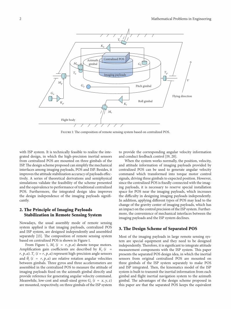
Figure 1 The composition of remote sensing system based on centralized POS
with ISP system It is technically feasible to realize the inte-grated design in which the high-precision inertial sensorsfrom centralized POS are mounted on three gimbals of theISPThe design scheme proposed can simplify themechanicalinterfaces among imaging payloads POS and ISP Besides itimproves the attitude stabilization accuracy of payloads effec-tively A series of theoretical derivations and semiphysicalsimulations validate the feasibility of the scheme presentedand the equivalence to performance of traditional centralizedPOS Furthermore the integrated design idea improvesthe design independence of the imaging payloads signifi-cantly
2 The Principle of Imaging PayloadsStabilization in Remote Sensing System
Nowadays the usual assembly mode of remote sensingsystem applied is that imaging payloads centralized POSand ISP system are designed independently and assembledseparately [13] The composition of remote sensing systembased on centralized POS is shown in Figure 1
From Figure 1 119872119894 (119894 = 119903 119901 119886) denote torque motorsAmplification gain coefficients are described by 119870119894 (119894 =119903 119901 119886) 119879119894 (119894 = 119903 119901 119886) represent high-precision angle sensorsand 120579119894 (119894 = 119903 119901 119886) are relative rotation angular velocitiesbetween gimbals Three gyros and three accelerometers areassembled in the centralized POS to measure the attitude ofimaging payloads fixed on the azimuth gimbal directly andprovide reference for generating angular velocity commandMeanwhile low-cost and small-sized gyros 119866119894 (119894 = 119909 119910 119911)are mounted respectively on three gimbals of the ISP system
to provide the corresponding angular velocity informationand conduct feedback control [19 20]
When the system works normally the position velocityand attitude information of imaging payloads provided bycentralized POS can be used to generate angular velocitycommand which transformed into torque motor controlsignals driving three gimbals to expected position Howeversince the centralized POS is fixedly connected with the imag-ing payloads it is necessary to reserve special installationspace for POS near the imaging payloads which increasesthe difficulty in designing imaging payloads independentlyIn addition applying different types of POS may lead to thechange of the gravity center of imaging payloads which hasan impact on the control precision of the ISP system Further-more the convenience of mechanical interfaces between theimaging payloads and the ISP system declines
3 The Design Scheme of Separated POS
Most of the imaging payloads in large remote sensing sys-tem are special equipment and they need to be designedindependentlyTherefore it is significant to integrate attitudemeasurement components with the ISP system This paperpresents the separated POS design idea in which the inertialsensors from original centralized POS are mounted onthree gimbals of the ISP system separately to make POSand ISP integrated Then the kinematics model of the ISPsystem is built to transmit the inertial information from eachgimbal and flight inertial navigation system to the azimuthgimbal The advantages of the design scheme proposed inthis paper are that the separated POS keeps the equivalent
Mathematical Problems in Engineering 3
performance with traditional centralized POS but it reducesthe number of inertial devices and simplifies the mechanicaland electronic interfaces between the imaging payloads andISP system compared with traditional large remote sensingsystem Moreover the separated system enhances the controlaccuracy of the ISP system and the design independence ofthe imaging payloads significantly
31 Coordinates Commonly Used in Centralized POS andISP System Imaging payloads usually need to be stable inlocal geographical coordinate One motion vector may havedifferent expressions in different coordinates Therefore themotion vectors should be decomposed to the specified coor-dinates in attitude determination and gimbals control Thecoordinates usednormally in inertially stabilized platformareshown as follows
(1) Navigation coordinate119874119909119899119910119899119911119899 119909119899 119910119899 and 119911119899 denotethe east north and up directions of the local horizon
(2) Base coordinate119874119909119887119910119887119911119887 119909119887 119910119887 and 119911119887 represent theright forward and up directions of the flight body
(3) Roll coordinate 119874119909119903119910119903119911119903 roll axes 119910119903 and 119910119887 are inthe same direction and the roll coordinate is rotatedroll angle 120579119903 around axis 119910119887 with respect to basecoordinate
(4) Pitch coordinate 119874119909119901119910119901119911119901 pitch axis 119909119901 is coaxialwith 119909119903 and the pitch coordinate is turned pitch angle120579119901 around axis 119909119903 with respect to roll coordinate
(5) Azimuth coordinate 119874119909119886119910119886119911119886 azimuth axis 119911119886 iscollinear with 119911119901 and the azimuth coordinate isrotated azimuth angle 120579119886 around axis 119911119901 with respectto pitch coordinate
Roll angle 120579119903 pitch angle 120579119901 and azimuth angle 120579119886 standfor the rotation angles of roll-pitch-azimuth coordinates withrespect to body coordinate [6] (The positive rotation iscounterclockwise) The variables in different coordinates canbe converted mutually through these angles The coordinatesof the ISP system and the conversion relationship are shownin Figure 2
32 The Design Philosophy of Separated POS The key pointsof separated POS integrated with ISP system are as followsthe inertial sensors (three gyros and three accelerometers) areno longer fixedly connected with imaging payloads as cen-tralized POS they are separately mounted on three gimbalsof the ISP system to make up separate inertial measurementunits According to the kinematics model of the ISP systembuilt below the motion information provided by inertialsensors fixed on three gimbals and the information providedby flight inertial navigation system are transmitted to imagingpayloads generating the inertial measurement signals whichreflect the motion status of imaging payloads Utilizing thesignals with inertial navigation algorithm can achieve theperformance of separated POS The scheme is equivalentto fixing virtual centralized POS on the imaging payloadswhich is called ldquovirtual centralized POSrdquo in Figure 3 Thecomposition of remote sensing system with separated POS isshown in Figure 3
p
p
r
a
O
r
a
zb
ya
yp
r
a
p
xr
xb
xaxp
zrzp za
yb yr
Figure 2 Gimbals coordinate converted diagrammatic sketch
In Figure 3 the sensitive axes of three gyros are respec-tively coaxially mounted with roll axis pitch axis andazimuth axis of gimbals tomeasure angular velocities of threeframes with respect to inertial space Two accelerometers119860119909 119860119910 are orthogonally mounted on the pitch gimbal andtheir sensitive axes are respectively collinear with 119909119901 and 119910119901to measure specific forces of the pitch gimbal in horizontaldirection Another accelerometer 119860119911 is fixed on the azimuthgimbal and its sensitive axis is collinear with 119911119886 of azimuthcoordinate tomeasure specific forces of payloads along 119911-axisdirectly Angle sensors are installed at the rotation axis of eachgimbal and their sensitive axes are coaxial with each gimbalspin axis to measure the relative angles between gimbals Theflight inertial device is fixed on flight body tomeasure inertialinformation 120596119894119887
In this scheme the palstances 120596119894119903 120596119894119901 120596119894119886 of gimbals withrespect to inertial space and angular velocity 120596119894119887 of flightbody constitute the angular velocity of azimuth coordinateattached to imaging payloadsTherefore the outputs of gyrosand flight inertial navigation system constitute the angularvelocities equal to the measurements provided by centralizedPOS namely achieving the performance of separated POS
Compared with centralized POS the separated POSadopted in remote sensing system has the following advan-tages firstly the integrated design scheme simplifies themechanical interfaces between imaging payloads and POSISP as well as improving the design independence Secondlythe gyros mounted on three gimbals can also provide ratefeedback information which enhances the feedback controlprecision and improves the synchronization between motionmeasurement and control command significantly Thirdlythe number of inertial sensors declines in contrast to tradi-tional centralized POS
33 The Kinematics Model of the Separated POS Integratedwith ISP System Since the inertial sensors of the separatedPOS are mounted on three gimbals of the ISP system theangular velocities and specific forces output cannot reflect themotion status of the imaging payloads fixed on the azimuth
4 Mathematical Problems in Engineering
Pitch gimbal
Roll gimbal
Azimuthgimbal
Imaging payloads
Flying direction
Virtualcentralized POS
Flight inertial navigation system
V
Flight body
Tr
Tp
aziaz
Ka
Kr
Ma
Mr
Ta
ipx
Mp
Gx
Gy
Gz
Kp
Ap
Ar
Aa
yr
yb
xb
xp
iry
ibzibx
zb
iby
Figure 3 Diagram of remote sensing system with separated POS
gimbal directly Therefore it is necessary to convert andtransmit the signal from the flight inertial navigation systemand the inertial sensors of separated POS to the azimuthgimbal and then obtain the motion information of imagingpayloads and realize the attitudes measurement and stabilityIn other words virtual centralized POS is generated cor-respondingly by converting the information from inertialsensors of the separated POS to imaging payloads The maincontent of this section consists of the conversion and trans-mission of inertial signals from gyros and accelerometers
331TheConversion and Transmission ofMeasurement Signalfrom Gyros The angular velocities of three gimbals withrespect to inertial space are measured by gyros fixed ongimbalsThe gyros in flight navigation system can provide theangular velocity of flight body with respect to inertial spaceThey need to be converted and transmitted to imaging pay-loads to calculate attitudes and generate control commandAs follows the conversion and transmissionmodel of inertialangular velocities is derived
Assume that 997888120596119887119894119887 = [120596119894119887119909 120596119894119887119910 120596119894119887119911]119879 denotes angularvelocity of flight body The angular velocity of roll gim-bal with respect to inertial space is expressed as 997888120596119903119894119903 =[120596119894119903119909 120596119894119903119910 120596119894119903119911]119879 997888120596119901119894119901 = [120596119894119901119909 120596119894119901119910 120596119894119901119911]119879 represents theangular velocity of pitch gimbal with relative to inertial space997888120596119886119894119886 = [120596119894119886119909 120596119894119886119910 120596119894119886119911]119879 is the angular velocity of azimuthgimbal with relative to inertial space And the angularvelocities of the gimbals obtained by pitch-roll-azimuth
sequence of rotations are described by 120579119901 120579119903 and 120579119886 respec-tively
Firstly the transmission relationship of angular velocitiesbetween flight body and roll gimbal is discussed Since theroll gimbal is mounted on the base of flight body the angularvelocity of roll gimbal is comprised of angular velocity offlight body and spin velocity of roll gimbal The angularvelocity of flight body is projected to roll gimbal and addedto spin velocity of roll gimbal the result is given by
997888120596119903119894119903 = 119862119903119887997888120596 119894119887 + 997888120596119887119903 =[[[[
120596119894119887119909 cos 120579119903 minus 120596119894119887119911 sin 120579119903120596119894119887119910 + 120579119903
120596119894119887119909 sin 120579119903 + 120596119894119887119911 cos 120579119903
]]]] (1)
Secondly on the base of angular velocity of roll gimbalobtained the transmission rule of angular velocities betweenroll and pitch gimbals is discussed Since the rotation axis ofpitch gimbal is fixed on the roll gimbal and orthogonal to therotation axis of roll gimbal the angular velocity of pitch frameis made up of angular velocity of roll gimbal and spin velocityof pitch gimbal The velocity of roll gimbal is projected topitch gimbal and added to spin velocity of pitch gimbal theresult is given by
997888120596119901119894119901 = 119862119901119903997888120596 119894119903 + 997888120596119903119901 =[[[[
120596119894119903119909 + 120579119901120596119894119903119910 cos 120579119901 + 120596119894119903119911 sin 120579119901minus120596119894119903119910 sin 120579119901 + 120596119894119903119911 cos 120579119901
]]]] (2)
Mathematical Problems in Engineering 5
Thirdly the angular velocity of azimuth gimbal is ob-tained from projection of angular velocity of pitch gimbalSince the azimuth gimbal is installed in the pitch gimbalthrough bearings the rotation axis of azimuth gimbal iscoaxial with the axis 119911119886 of azimuth coordinate Consideringthe spin velocity of azimuth gimbal the angular velocity ofazimuth gimbal can be expressed as
997888120596119886119894119886 = 119862119886119901997888120596119901119894119901 + 997888120596119901119886 =[[[[
120596119894119901119909 cos 120579119886 + 120596119894119901119910 sin 120579119886minus120596119894119901119909 sin 120579119886 + 120596119894119901119910 cos 120579119886120596119894119901119911 + 120579119886
]]]] (3)
According to (1) (2) and (3) the angular velocity ofimaging payloads with respect to inertial space is given by
997888120596119886119894119886 = [[[
120596119894119886119909120596119894119886119910120596119894119886119911]]]
= [[[[
cos 120579119886 cos 120579119903 + sin 120579119886 sin 120579119901 sin 120579119903 sin 120579119886 cos 120579119901 sin 120579119886 sin 120579119901 cos 120579119903 minus cos 120579119886 sin 120579119903minus cos 120579119903 sin 120579119886 + cos 120579119886 sin 120579119901 sin 120579119903 cos 120579119886 sin 120579119901 cos 120579119886 sin 120579119901 cos 120579119903 + sin 120579119886 sin 120579119903
cos 120579119901 sin 120579119903 minus sin 120579119901 cos 120579119901 cos 120579119903]]]][[[
120596119894119887119909120596119894119887119910120596119894119887119911]]]
+ [[[[
cos 120579119901 sin 120579119886 cos 120579119886 0cos 120579119886 cos 120579119901 minus sin 120579119901 0minus sin 120579119901 0 1
]]]]
[[[[
120579119903120579119901120579119886
]]]]
(4)
From (4) the angular velocity of imaging payloads withrespect to inertial space can be obtained according to angularvelocities of flight body 120596119894119887119909 120596119894119887119910 and 120596119894119887119911 and spin velocitiesof gimbals 120579119903 120579119901 and 120579119886 then angular velocity commandcan be generated to make platform stable However theprecision of rotational rates between gimbals is limited byangle sensors mounted along rotation axis of gimbals Theangular velocities are calculated by angle differential but thedeviation of angle differential is so large that the stabilizationprecision of imaging payloads declinesTherefore it is signif-icant to enhance the stabilization of platform by improvingthe measurement precision of spin velocities of gimbals
The precision of angular velocity measured by gyro ismuch higher than angle differential of angle sensor There-fore it can improve the stabilization of platform by fixinggyros on three gimbals to measure spin velocities of gimbals
120596119894119903119910 = 120596119894119887119910 + 120579119903120596119894119901119909 = 120596119894119903119909 + 120579119901120596119894119886119911 = 120596119894119901119911 + 120579119886
(5)
Thus the angular velocities of gimbals with respect toinertial space can be measured directly by gyros instead ofoutput derivation from angle sensors
According to (1) and (2) it can be known that
120596119901119894119901119909 = 120596119903119894119903119910 cos 120579119901 + 120596119903119894119903119911 sin 120579119901 (6)
120596119903119894119903119911 = 120596119887119894119887119909 sin 120579119903 + 120596119887119894119887119911 cos 120579119903 (7)
Substituting (7) into (6) one obtains
120596119901119894119901119910 = 120596119903119894119903119910 cos 120579119901 + (120596119887119894119887119909 sin 120579119903 + 120596119887119894119887119911 cos 120579119903) sin 120579119901 (8)
Substituting (8) into (3) one obtains
[[[
120596119894119886119909120596119894119886119910120596119894119886119911]]]= [[[
cos 120579119886 cos 120579119901 sin 120579119886 0minus sin 120579119886 cos 120579119901 cos 120579119886 00 0 1
]]][[[
120596119894119901119909120596119894119903119910120596119894119886119911]]]
+[[[[[
sin 120579119903 sin 120579119901 sin 120579119886 0 cos 120579119903 sin 120579119901 sin 120579119886sin 120579119903 sin 120579119901 cos 120579119886 0 cos 120579119903 sin 120579119901 cos 120579119886
0 0 0
]]]]][[[
120596119894119887119909120596119894119887119910120596119894119887119911]]]
(9)
From (9) it can be seen that angular velocities of imagingpayloads with respect to inertial space can be obtainedaccording to the angular velocities of gimbals 120596119894119901119909 120596119894119903119910 and120596119894119886119911 and the angular velocity of flight body 120596119894119887332 The Conversion and Transmission of Measurement Sig-nal from Accelerometers The sensitive axes of three accelero-meters are always orthogonal which decreases the difficultyin decoupling According to the principle of coordinatetransformation the outputs of two accelerometers fixed onthe pitch gimbal are projected to azimuth coordinate to getthree-axis acceleration of azimuth gimbal
[[[
acc119886119909acc119886119910acc119886119911
]]]= [[[
cos 120579119886 sin 120579119886 0minus sin 120579119886 cos 120579119886 00 0 1
]]][[[
acc119901119909acc119901119910acc119886119911
]]] (10)
From (10) the information of the accelerometers fixedseparately on different gimbals is utilized to obtain the outputof accelerometers equal to that in centralized POS
Therefore the inertial information measured by gyrosand accelerometers fixed on gimbals and the signals gener-ated from flight inertial navigation system can be transmitted
6 Mathematical Problems in Engineering
to the imaging payloads according to (9) and (10) Afterattitude calculation the corresponding function of separatedPOS can be realized
4 Simulation
To validate the feasibility and precision of the separatedPOS proposed in this paper the semiphysical simulations areconducted The scheme is as follows
(1) Utilize trajectory generator to produce exact naviga-tion data (including the output of three gyros andthree accelerometers attitude and position informa-tion of the imaging payloads) in different motionconditions to test the performance of the separatedPOS and the centralized POS
(2) Add the sensor errors which reflect the sensor perfor-mance to the exact data output by trajectory generatorto generate semiphysical simulation data
(3) Read the semiphysical data to calculate the attitudeof imaging payloads in the separated POS and thecentralized POS respectively
(4) Compare the calculation results with the exact atti-tude from trajectory generator to test the equivalenceof the main performance between the separated POSand the centralized POS
Two kinds of experiments are designed under angularmotion and variable rectilinear motion to compare theperformances of the separated POS and the centralized POS
41 The Performance Comparison of Separated POS andCentralized POS in Angular Motion When angular motionof gimbals exists the outputs of gyros and accelerometersfixed on gimbals are projected to the azimuth gimbal throughangles provided by angle sensors Thus the precision of theangle sensors has an effect on the performance of separatedPOSThis section analyzes the performance of separated POSand centralized POSwhen the angle sensor error exists or not
411 Trajectory Generation The ideal navigation data ofthe separated POS and the centralized POS is generatedrespectively by trajectory generator and the length of datais 600 s In the process the base of platform keeps motionlessand the three gimbals keep rotating around each axis at theuniform speedsThe azimuth angle ranges from 0∘ to 20∘ thepitch angle ranges from 0∘ to 10∘ and the roll angle rangesfrom 0∘ to 5∘ The attitude variation curve of the platform isshown in Figure 4
Based on the ideal data generated by trajectory generatorthe sensor errors reflecting real sensor performance are addedto produce semiphysical simulation data The constant drift-ing of gyro is 001∘h and the constant bias of accelerometeris 50 ug (119892 =97803267714ms2)
412 The POS Performance Comparison Experiments withoutAngle Sensor Error After reading the semiphysical simu-lation data added to inertial sensor errors from gyro and
0
5
Roll
angl
e (∘ )
0
20
40
Azi
mut
h an
gle(
∘ )
0
10
20
Pitc
h an
gle (
∘ )
100 200 300 400 500 6000Time (s)
100 200 300 400 500 6000Time (s)
100 200 300 400 500 6000Time (s)
Figure 4 The platform attitude generated by trajectory generator
accelerometer the attitude of the imaging payloads is calcu-lated by the separated POS and the centralized POS respec-tively Then the comparison between calculation results andideal attitude from trajectory generator is carried out Theattitude errors are shown in Figure 5(a) the differencesbetween attitude errors of separated POS and centralizedPOS are shown in Figure 5(b) According to Figure 5 theattitude error characteristics can be displayed visually toanalyze whether the performance of separated POS is equalto centralized POS or not when angle sensor error does notexist
From Figure 5 the attitude errors of separated POS andcentralized POS are similar And the maximum three-axisattitude (azimuth angle pitch angle and roll angle) errorsof separated POScentralized POS caused by errors fromgyro and accelerometer are 7653 times 10minus4∘7593 times 10minus4∘2151 times 10minus3∘2148 times 10minus3∘ and 1037 times 10minus3∘1037 times10minus3∘ respectively The minute differences of attitude errorsbetween separated POS and centralized POS during thewhole process are shown in Figure 5(b) The maximumdifferences of the three-axis attitude errors are 7353 times 10minus7∘2978 times 10minus6∘ and 5772 times 10minus6∘ respectively which canbe ignored compared with the corresponding attitude errorsshown in Figure 5(a) Therefore the equivalence of theseparated POS and the centralized POS is validated whenangle sensor error does not exist
413 The POS Performance Comparison Experiments withAngle Sensor Error The angle sensor error 210158401015840 is addedto inertial data generated by trajectory generator And theattitudes calculated by separated POS and centralized POSrespectively are compared to ideal attitudes The attitudeerrors are shown in Figure 6(a) and the minute differencesbetween the attitude errors of two POSs are shown in Fig-ure 6(b) Based on Figure 6 the attitude error characteristicscan be displayed visually to analyze whether the performanceof separated POS is equal to centralized POS or not whenangle sensor error exists
Mathematical Problems in Engineering 7
0 100 200 300 400 500 600Time (s)
0 100 200 300 400 500 600Time (s)
Separated pos attitude errorCentralized pos attitude error
Pitc
han
gle e
rror
(∘)
Roll
angl
e err
or(∘
)
times10minus3
times10minus3
times10minus3
minus1
minus05
0
Azi
mut
han
gle e
rror
(∘)
0
2
4
0
1
2
100 200 300 400 500 6000Time (s)
(a) The attitude errors of separated POS and centralized POS compared withideal attitudes
times10minus5
times10minus5
times10minus5
Diff
eren
ce o
f azi
mut
han
gle e
rror
s(∘ )
Diff
eren
ce o
f pitc
han
gle e
rror
s(∘ )
Diff
eren
ce o
f rol
lan
gle e
rror
s(∘ )
minus2
0
2
minus1
0
1
minus1
0
1
100 200 300 400 500 6000Time (s)
100 200 300 400 500 6000Time (s)
100 200 300 400 500 6000Time (s)
(b) The differences between attitude errors of separated POS and centralizedPOS
Figure 5 The attitude errors without angle sensor error
0 100 200 300 400 500 600Time (s)
0 100 200 300 400 500 600Time (s)
0 100 200 300 400 500 600Time (s)
Pitc
han
gle e
rror
(∘)
Roll
angl
e err
or(∘
)
times10minus3
times10minus3
times10minus3
Azi
mut
han
gle e
rror
(∘)
minus1
minus05
1
0
2
4
0
1
2
Separated POS attitude errorCentralized POS attitude error
(a) The attitude errors of separated POS and centralized POS compared withthe ideal attitudes
0 100 200 300 400 500 600Time (s)
minus5
0
5
Diff
eren
ce o
f azi
mut
han
gle e
rror
s(∘ )
Diff
eren
ce o
f pitc
han
gle e
rror
s(∘ )
Diff
eren
ce o
f rol
lan
gle e
rror
s(∘ )
times10minus4
times10minus4
times10minus4
minus1
0
1
0
2
4
100 200 300 400 500 6000Time (s)
100 200 300 400 500 6000Time (s)
(b) The differences between attitude errors of separated POS and centralizedPOS
Figure 6 The attitude errors with angle sensor error
8 Mathematical Problems in Engineering
0
10
20
Azi
mut
h an
gle(
∘ )
0
5
10
Pitc
h an
gle (
∘ )
0
5
Roll
angl
e(∘ )
100 200 300 400 500 6000Time (s)
100 200 300 400 500 6000Time (s)
100 200 300 400 500 6000Time (s)
(a) The attitude angle of platform
0
2
4
0
5
10
0
1
2
100 200 300 400 500 6000time (s)
100 200 300 400 500 6000time (s)
100 200 300 400 500 6000time (s)
Ve
(ms)
Vn
(ms)
Vu
(ms)
(b) The linear velocity of flight body
Figure 7 The attitude angle of platform and linear velocity of flight body produced by trajectory generator
From Figure 6 the attitude errors of separated POS andcentralized POS are similar And the maximum three-axisattitude (azimuth angle pitch angle and roll angle) errorsof separated POScentralized POS caused by errors addedfrom gyro accelerometer and angle sensor are 8331 times10minus4∘7593 times 10minus4∘ 2399 times 10minus3∘2148 times 10minus3∘ and 8057times10minus4∘1033 times 10minus3∘ respectively The small differencesbetween attitude errors of separated POS and centralized POSduring the whole process are shown in Figure 6(b)Themax-imum differences of the three-axis attitude errors are 7383 times10minus5∘ 2513times10minus4∘ and 2271times10minus4∘ respectively which canbe ignored compared with the corresponding attitude errorsshown in Figure 6(a)
Comparing the three-axis attitude errors in Figures 5(b)and 6(b) the differences between the attitude errors of twoPOSs increase after adding the angle sensor error and thecorresponding maximum values are 6747 times 10minus5∘ 2483 times10minus4∘ and 2213 times 10minus4∘ respectively They can also beneglected in contrast to the attitude errors calculated byseparated POS and centralized POS respectively Thereforethe equivalence of the separated and centralized POS is notinfluenced by angle sensor error
42 The Performance Comparison of Separated POS andCentralized POS in Variable Rectilinear Motion In the actualflight process the variable rectilinear motion of flight bodyhas an effect on attitude calculation precision of the inertiallystabilized platform Thus the influence of linear accelerationfrom flight body is analyzed in the separated POS and thecentralized POS Besides the performance comparison oftwo POSs is also discussed
421 Trajectory Generation The ideal navigation data ofthe separated POS and the centralized POS is respectivelygenerated by trajectory generator and the length of data
is 600 s In the process the velocity of flight body andthe attitude of imaging payloads change synchronously Thetrajectory includes three parts (1198791 1198792 and 1198793) and eachpart sustains 200 s In part 1198791 the azimuth angle ranges from0∘ to 20∘ and the velocity of flight body changes from 0 to5ms with constant acceleration at the same time in part 1198792pitch angle ranges from 0∘ to 10∘ meanwhile the velocityof flight body changes from 5ms to 10ms with constantacceleration in part 1198793 roll angle ranges from 0∘ to 5∘ andthe flight velocity also changes from 10ms to 5ms with con-stant acceleration The attitude and velocity variation curvesgenerated by trajectory generator are shown in Figure 7
The constant drifting of the gyro 001∘h the constantbias of accelerometer 50 ug and the angle sensor error 210158401015840 areadded to the ideal navigation data generated by trajectorygenerator to produce semiphysical simulation data
422 The POS Performance Comparison Experiments WhenFlight Body Moves with Variable Velocity Reading the semi-physical simulation data added to sensor errors the attitudeof the imaging payloads is calculated by separated POS andcentralized POS respectivelyThe attitude errors are shown inFigure 8(a) and the minute differences between the attitudeerrors of two POSs are shown in Figure 8(b) According toFigure 8 the attitude error characteristics can be displayedvisually to analyze whether the equivalence of the separatedand centralized POS exists or not when flight body moveswith variable velocity
From Figure 8 the attitude errors of the separated POSare similar to that of centralized POS And the maximumthree-axis attitude (azimuth angle pitch angle and roll angle)errors of separated POScentralized POS caused by sensorerrors are 5968 times 10minus5∘1443 times 10minus4∘ 2946 times 10minus3∘2728 times10minus3∘ and 5395 times 10minus4∘7493 times 10minus4∘ respectively Theminute differences between attitude errors of separated POS
Mathematical Problems in Engineering 9Pi
tch
angl
e err
or(∘
)Ro
llan
gle e
rror
(∘)
times10minus3
times10minus3
times10minus3
Azi
mut
han
gle e
rror
(∘)
Separated pos attitude errorCentralized pos attitude error
minus1
0
1
0
2
4
0
05
1
100 200 300 400 500 6000Time (s)
100 200 300 400 500 6000Time (s)
100 200 300 400 500 6000Time (s)
(a) The attitude errors of separated POS and centralized POS compared withthe ideal attitudes
Diff
eren
ce o
f azi
mut
han
gle e
rror
s(∘ )
Diff
eren
ce o
f pitc
han
gle e
rror
s(∘ )
Diff
eren
ce o
f rol
lan
gle e
rror
s(∘ )
times10minus4
times10minus4
times10minus4
minus2
0
2
0
2
4
minus5
0
5
100 200 300 400 500 6000Time (s)
100 200 300 400 500 6000Time (s)
100 200 300 400 500 6000Time (s)
(b) The differences between attitude errors of separated POS and centralizedPOS
Figure 8 The attitude errors with variable velocity motion
and centralized POS during the whole process are shown inFigure 8(b) And the maximum differences of the three-axisattitude errors are 1272 times 10minus4∘ 2173 times 10minus4∘ and 2098 times10minus4∘ which can be also ignored in contrast to the attitudeerror shown in Figure 8(a)
Therefore the attitude calculation results of the two POSsare similar namely the equivalence of the separated POS andthe centralized POS is validated even if the flight body moveswith variable velocity
5 Conclusion
Based on the analysis for characteristics of remote sens-ing system the design idea of separated POS integratedwith ISP system is proposed in this paper The attitude ofimaging payloads is obtained after calculating the inertialparameters from three gyros and accelerometers mountedon different gimbals and effective information introducedby flight inertial navigation system under the principle ofcoordinate transformation The separated POS not onlysimplifies the mechanical and electronic interfaces betweenimaging payloads and ISP system but also improves thetransmission precision of angular velocities among gimbalsMoreover the signals provided by gyros can also be applied asrate feedback directly which decreases the number of inertialsensors used in the ISP system but improves the controlprecision of gimbals A series of theoretical derivations andsemiphysical simulations under different motion conditionsvalidate the correctness and effectiveness of design schemepresented in this paper Besides the effective function equal to
centralized system the separated POS enhances the integra-tionwith the ISP system and decreases the cost and volume ofremote sensing system Furthermore it improves the designindependence of the imaging payloads significantly whichpredicts the good application prospects
Conflicts of Interest
The authors declare that there are no conflicts of interestregarding the publication of this paper
Acknowledgments
Thiswork is supported by theNational Natural Science Foun-dation of China under Grant no 61473019 Beijing NaturalScience Foundation under Grant no 4172036 Beijing Scienceand Technology Plan under Grant no D171100006217003and Open Research Fund of the State Key Laboratory ofTianjin Key Laboratory of Intelligent Information Processingin Remote Sensing under Grant no 2016-ZW-KFJJ-01
References
[1] X-L Chen H-M Zhao P-X Li and Z-Y Yin ldquoRemote sens-ing image-based analysis of the relationship between urban heatisland and land usecover changesrdquo Remote Sensing of Environ-ment vol 104 no 2 pp 133ndash146 2006
[2] S Gairola S Proches and D Rocchini ldquoHigh-resolution satel-lite remote sensing A new frontier for biodiversity explorationin Indian Himalayan forestsrdquo International Journal of RemoteSensing vol 34 no 6 pp 2006ndash2022 2013
10 Mathematical Problems in Engineering
[3] M Meroni A Schucknecht D Fasbender et al ldquoRemote sens-ing monitoring of land restoration interventions in semi-aridenvironments with a beforendashafter control-impact statisticaldesignrdquo International Journal of Applied Earth Observation andGeoinformation vol 59 pp 42ndash52 2017
[4] K Xu X Zhang Z Chen W Wu and T Li ldquoRisk assessmentfor wildfire occurrence in high-voltage power line corridorsby using remote-sensing techniques a case study in HubeiProvince Chinardquo International Journal of Remote Sensing vol37 no 20 pp 4818ndash4837 2016
[5] NThomas C Hendrix and R G Congalton ldquoA comparison ofurbanmappingmethods using high-resolution digital imageryrdquoPhotogrammetric Engineering and Remote Sensing vol 69 no 9pp 963ndash972 2003
[6] Y Zou and X Lei ldquoA compound control method based on theadaptive neural network and sliding mode control for inertialstable platformrdquo Neurocomputing vol 155 pp 286ndash294 2015
[7] X Zhou G Gong J Li H Zhang and R Yu ldquoDecoupling con-trol for a three-axis inertially stabilized platform used for aerialremote sensingrdquo Transactions of the Institute of Measurementand Control vol 37 no 9 pp 1135ndash1145 2015
[8] Y Zhang C Du and Q Mu ldquoRandom error modelling andcompensation of accelerometer in airborne remote sensing sta-bilized platformrdquo Transactions of the Institute of Measurementand Control vol 35 no 4 pp 503ndash509 2013
[9] J M Hilkert ldquoInertially stabilized platform technology con-cepts and principlesrdquo IEEE Control Systems Magazine vol 28no 1 pp 26ndash46 2008
[10] M K Masten ldquoInertially stabilized platforms for optical imag-ing systems tracking dynamic targets with mobile sensorsrdquoIEEE Control Systems Magazine vol 28 no 1 pp 47ndash64 2008
[11] H G Wang and T C Williams ldquoStrategic inertial navigationsystems high-accuracy inertially stabilized platforms for hostileenvironmentsrdquo IEEE Control Systems Magazine vol 28 no 1pp 65ndash85 2008
[12] Q Mu G Liu and X Lei ldquoA RBFNN-Based Adaptive Distur-bance Compensation Approach Applied to Magnetic Suspen-sion Inertially Stabilized Platformrdquo Mathematical Problems inEngineering vol 2014 Article ID 657985 2014
[13] X Zhou Y Jia Q Zhao and T Cai ldquoDual-rate-loop controlbased on disturbance observer of angular acceleration for athree-axis aerial inertially stabilized platformrdquo ISA Transac-tions vol 63 pp 288ndash298 2016
[14] J Fang and R Yin ldquoAn adaptive nonlinear control for gyrostabilized platform based on neural networks and disturbanceobserverrdquo Mathematical Problems in Engineering vol 2014Article ID 472815 2014
[15] X Zhou B Zhao W Liu H Yue R Yu and Y Zhao ldquoA com-pound scheme on parameters identification and adaptive com-pensation of nonlinear friction disturbance for the aerial iner-tially stabilized platformrdquo ISA Transactions vol 67 pp 293ndash305 2017
[16] J C Fang Z H Qi andM Y Zhong ldquoFeedforward compensa-tion method for three axes inertially stabilized platform imbal-ance torquerdquo Journal of Chinese Inertial Technology vol 18 no1 pp 38ndash43 2010
[17] C Bai and Z Zhang ldquoAcceleration-based mass imbalance feed-forward compensation for inertial stabilized platformrdquo Interna-tional Journal of Control Automation and Systems vol 12 no3 pp 609ndash617 2014
[18] S Li andM Zhong ldquoHigh-precision disturbance compensationfor a three-axis gyro-stabilized camera mountrdquo IEEEASMETransactions onMechatronics vol 20 no 6 pp 3135ndash3147 2015
[19] Y Zhang and R Zhu ldquoA novel gyro installation mode of three-axis stabilized platform used for airborne earth observationrdquoHangkong XuebaoActa Aeronautica et Astronautica Sinica vol31 no 3 pp 614ndash619 2010
[20] W Ji Q Li B Xu D Zhao and S Fang ldquoAdaptive fuzzy PIDcomposite control with hysteresis-band switching for line ofsight stabilization servo systemrdquo Aerospace Science and Tech-nology vol 15 no 1 pp 25ndash32 2011
Hindawiwwwhindawicom Volume 2018
MathematicsJournal of
Hindawiwwwhindawicom Volume 2018
Mathematical Problems in Engineering
Applied MathematicsJournal of
Hindawiwwwhindawicom Volume 2018
Probability and StatisticsHindawiwwwhindawicom Volume 2018
Journal of
Hindawiwwwhindawicom Volume 2018
Mathematical PhysicsAdvances in
Complex AnalysisJournal of
Hindawiwwwhindawicom Volume 2018
OptimizationJournal of
Hindawiwwwhindawicom Volume 2018
Hindawiwwwhindawicom Volume 2018
Engineering Mathematics
International Journal of
Hindawiwwwhindawicom Volume 2018
Operations ResearchAdvances in
Journal of
Hindawiwwwhindawicom Volume 2018
Function SpacesAbstract and Applied AnalysisHindawiwwwhindawicom Volume 2018
International Journal of Mathematics and Mathematical Sciences
Hindawiwwwhindawicom Volume 2018
Hindawi Publishing Corporation httpwwwhindawicom Volume 2013Hindawiwwwhindawicom
The Scientific World Journal
Volume 2018
Hindawiwwwhindawicom Volume 2018Volume 2018
Numerical AnalysisNumerical AnalysisNumerical AnalysisNumerical AnalysisNumerical AnalysisNumerical AnalysisNumerical AnalysisNumerical AnalysisNumerical AnalysisNumerical AnalysisNumerical AnalysisNumerical AnalysisAdvances inAdvances in Discrete Dynamics in
Nature and SocietyHindawiwwwhindawicom Volume 2018
Hindawiwwwhindawicom
Dierential EquationsInternational Journal of
Volume 2018
Hindawiwwwhindawicom Volume 2018
Decision SciencesAdvances in
Hindawiwwwhindawicom Volume 2018
AnalysisInternational Journal of
Hindawiwwwhindawicom Volume 2018
Stochastic AnalysisInternational Journal of
Submit your manuscripts atwwwhindawicom
2 Mathematical Problems in Engineering
Pitch gimbal
Roll gimbal
Imaging payloads
Flight body
Flying direction
V
Centralized POSAzimuthgimbal
Tr
Ka
Kp
Tp
Kr
Gy
GzMa
Ta
Mr
Gx
Mp
Figure 1 The composition of remote sensing system based on centralized POS
with ISP system It is technically feasible to realize the inte-grated design in which the high-precision inertial sensorsfrom centralized POS are mounted on three gimbals of theISPThe design scheme proposed can simplify themechanicalinterfaces among imaging payloads POS and ISP Besides itimproves the attitude stabilization accuracy of payloads effec-tively A series of theoretical derivations and semiphysicalsimulations validate the feasibility of the scheme presentedand the equivalence to performance of traditional centralizedPOS Furthermore the integrated design idea improvesthe design independence of the imaging payloads signifi-cantly
2 The Principle of Imaging PayloadsStabilization in Remote Sensing System
Nowadays the usual assembly mode of remote sensingsystem applied is that imaging payloads centralized POSand ISP system are designed independently and assembledseparately [13] The composition of remote sensing systembased on centralized POS is shown in Figure 1
From Figure 1 119872119894 (119894 = 119903 119901 119886) denote torque motorsAmplification gain coefficients are described by 119870119894 (119894 =119903 119901 119886) 119879119894 (119894 = 119903 119901 119886) represent high-precision angle sensorsand 120579119894 (119894 = 119903 119901 119886) are relative rotation angular velocitiesbetween gimbals Three gyros and three accelerometers areassembled in the centralized POS to measure the attitude ofimaging payloads fixed on the azimuth gimbal directly andprovide reference for generating angular velocity commandMeanwhile low-cost and small-sized gyros 119866119894 (119894 = 119909 119910 119911)are mounted respectively on three gimbals of the ISP system
to provide the corresponding angular velocity informationand conduct feedback control [19 20]
When the system works normally the position velocityand attitude information of imaging payloads provided bycentralized POS can be used to generate angular velocitycommand which transformed into torque motor controlsignals driving three gimbals to expected position Howeversince the centralized POS is fixedly connected with the imag-ing payloads it is necessary to reserve special installationspace for POS near the imaging payloads which increasesthe difficulty in designing imaging payloads independentlyIn addition applying different types of POS may lead to thechange of the gravity center of imaging payloads which hasan impact on the control precision of the ISP system Further-more the convenience of mechanical interfaces between theimaging payloads and the ISP system declines
3 The Design Scheme of Separated POS
Most of the imaging payloads in large remote sensing sys-tem are special equipment and they need to be designedindependentlyTherefore it is significant to integrate attitudemeasurement components with the ISP system This paperpresents the separated POS design idea in which the inertialsensors from original centralized POS are mounted onthree gimbals of the ISP system separately to make POSand ISP integrated Then the kinematics model of the ISPsystem is built to transmit the inertial information from eachgimbal and flight inertial navigation system to the azimuthgimbal The advantages of the design scheme proposed inthis paper are that the separated POS keeps the equivalent
Mathematical Problems in Engineering 3
performance with traditional centralized POS but it reducesthe number of inertial devices and simplifies the mechanicaland electronic interfaces between the imaging payloads andISP system compared with traditional large remote sensingsystem Moreover the separated system enhances the controlaccuracy of the ISP system and the design independence ofthe imaging payloads significantly
31 Coordinates Commonly Used in Centralized POS andISP System Imaging payloads usually need to be stable inlocal geographical coordinate One motion vector may havedifferent expressions in different coordinates Therefore themotion vectors should be decomposed to the specified coor-dinates in attitude determination and gimbals control Thecoordinates usednormally in inertially stabilized platformareshown as follows
(1) Navigation coordinate119874119909119899119910119899119911119899 119909119899 119910119899 and 119911119899 denotethe east north and up directions of the local horizon
(2) Base coordinate119874119909119887119910119887119911119887 119909119887 119910119887 and 119911119887 represent theright forward and up directions of the flight body
(3) Roll coordinate 119874119909119903119910119903119911119903 roll axes 119910119903 and 119910119887 are inthe same direction and the roll coordinate is rotatedroll angle 120579119903 around axis 119910119887 with respect to basecoordinate
(4) Pitch coordinate 119874119909119901119910119901119911119901 pitch axis 119909119901 is coaxialwith 119909119903 and the pitch coordinate is turned pitch angle120579119901 around axis 119909119903 with respect to roll coordinate
(5) Azimuth coordinate 119874119909119886119910119886119911119886 azimuth axis 119911119886 iscollinear with 119911119901 and the azimuth coordinate isrotated azimuth angle 120579119886 around axis 119911119901 with respectto pitch coordinate
Roll angle 120579119903 pitch angle 120579119901 and azimuth angle 120579119886 standfor the rotation angles of roll-pitch-azimuth coordinates withrespect to body coordinate [6] (The positive rotation iscounterclockwise) The variables in different coordinates canbe converted mutually through these angles The coordinatesof the ISP system and the conversion relationship are shownin Figure 2
32 The Design Philosophy of Separated POS The key pointsof separated POS integrated with ISP system are as followsthe inertial sensors (three gyros and three accelerometers) areno longer fixedly connected with imaging payloads as cen-tralized POS they are separately mounted on three gimbalsof the ISP system to make up separate inertial measurementunits According to the kinematics model of the ISP systembuilt below the motion information provided by inertialsensors fixed on three gimbals and the information providedby flight inertial navigation system are transmitted to imagingpayloads generating the inertial measurement signals whichreflect the motion status of imaging payloads Utilizing thesignals with inertial navigation algorithm can achieve theperformance of separated POS The scheme is equivalentto fixing virtual centralized POS on the imaging payloadswhich is called ldquovirtual centralized POSrdquo in Figure 3 Thecomposition of remote sensing system with separated POS isshown in Figure 3
p
p
r
a
O
r
a
zb
ya
yp
r
a
p
xr
xb
xaxp
zrzp za
yb yr
Figure 2 Gimbals coordinate converted diagrammatic sketch
In Figure 3 the sensitive axes of three gyros are respec-tively coaxially mounted with roll axis pitch axis andazimuth axis of gimbals tomeasure angular velocities of threeframes with respect to inertial space Two accelerometers119860119909 119860119910 are orthogonally mounted on the pitch gimbal andtheir sensitive axes are respectively collinear with 119909119901 and 119910119901to measure specific forces of the pitch gimbal in horizontaldirection Another accelerometer 119860119911 is fixed on the azimuthgimbal and its sensitive axis is collinear with 119911119886 of azimuthcoordinate tomeasure specific forces of payloads along 119911-axisdirectly Angle sensors are installed at the rotation axis of eachgimbal and their sensitive axes are coaxial with each gimbalspin axis to measure the relative angles between gimbals Theflight inertial device is fixed on flight body tomeasure inertialinformation 120596119894119887
In this scheme the palstances 120596119894119903 120596119894119901 120596119894119886 of gimbals withrespect to inertial space and angular velocity 120596119894119887 of flightbody constitute the angular velocity of azimuth coordinateattached to imaging payloadsTherefore the outputs of gyrosand flight inertial navigation system constitute the angularvelocities equal to the measurements provided by centralizedPOS namely achieving the performance of separated POS
Compared with centralized POS the separated POSadopted in remote sensing system has the following advan-tages firstly the integrated design scheme simplifies themechanical interfaces between imaging payloads and POSISP as well as improving the design independence Secondlythe gyros mounted on three gimbals can also provide ratefeedback information which enhances the feedback controlprecision and improves the synchronization between motionmeasurement and control command significantly Thirdlythe number of inertial sensors declines in contrast to tradi-tional centralized POS
33 The Kinematics Model of the Separated POS Integratedwith ISP System Since the inertial sensors of the separatedPOS are mounted on three gimbals of the ISP system theangular velocities and specific forces output cannot reflect themotion status of the imaging payloads fixed on the azimuth
4 Mathematical Problems in Engineering
Pitch gimbal
Roll gimbal
Azimuthgimbal
Imaging payloads
Flying direction
Virtualcentralized POS
Flight inertial navigation system
V
Flight body
Tr
Tp
aziaz
Ka
Kr
Ma
Mr
Ta
ipx
Mp
Gx
Gy
Gz
Kp
Ap
Ar
Aa
yr
yb
xb
xp
iry
ibzibx
zb
iby
Figure 3 Diagram of remote sensing system with separated POS
gimbal directly Therefore it is necessary to convert andtransmit the signal from the flight inertial navigation systemand the inertial sensors of separated POS to the azimuthgimbal and then obtain the motion information of imagingpayloads and realize the attitudes measurement and stabilityIn other words virtual centralized POS is generated cor-respondingly by converting the information from inertialsensors of the separated POS to imaging payloads The maincontent of this section consists of the conversion and trans-mission of inertial signals from gyros and accelerometers
331TheConversion and Transmission ofMeasurement Signalfrom Gyros The angular velocities of three gimbals withrespect to inertial space are measured by gyros fixed ongimbalsThe gyros in flight navigation system can provide theangular velocity of flight body with respect to inertial spaceThey need to be converted and transmitted to imaging pay-loads to calculate attitudes and generate control commandAs follows the conversion and transmissionmodel of inertialangular velocities is derived
Assume that 997888120596119887119894119887 = [120596119894119887119909 120596119894119887119910 120596119894119887119911]119879 denotes angularvelocity of flight body The angular velocity of roll gim-bal with respect to inertial space is expressed as 997888120596119903119894119903 =[120596119894119903119909 120596119894119903119910 120596119894119903119911]119879 997888120596119901119894119901 = [120596119894119901119909 120596119894119901119910 120596119894119901119911]119879 represents theangular velocity of pitch gimbal with relative to inertial space997888120596119886119894119886 = [120596119894119886119909 120596119894119886119910 120596119894119886119911]119879 is the angular velocity of azimuthgimbal with relative to inertial space And the angularvelocities of the gimbals obtained by pitch-roll-azimuth
sequence of rotations are described by 120579119901 120579119903 and 120579119886 respec-tively
Firstly the transmission relationship of angular velocitiesbetween flight body and roll gimbal is discussed Since theroll gimbal is mounted on the base of flight body the angularvelocity of roll gimbal is comprised of angular velocity offlight body and spin velocity of roll gimbal The angularvelocity of flight body is projected to roll gimbal and addedto spin velocity of roll gimbal the result is given by
997888120596119903119894119903 = 119862119903119887997888120596 119894119887 + 997888120596119887119903 =[[[[
120596119894119887119909 cos 120579119903 minus 120596119894119887119911 sin 120579119903120596119894119887119910 + 120579119903
120596119894119887119909 sin 120579119903 + 120596119894119887119911 cos 120579119903
]]]] (1)
Secondly on the base of angular velocity of roll gimbalobtained the transmission rule of angular velocities betweenroll and pitch gimbals is discussed Since the rotation axis ofpitch gimbal is fixed on the roll gimbal and orthogonal to therotation axis of roll gimbal the angular velocity of pitch frameis made up of angular velocity of roll gimbal and spin velocityof pitch gimbal The velocity of roll gimbal is projected topitch gimbal and added to spin velocity of pitch gimbal theresult is given by
997888120596119901119894119901 = 119862119901119903997888120596 119894119903 + 997888120596119903119901 =[[[[
120596119894119903119909 + 120579119901120596119894119903119910 cos 120579119901 + 120596119894119903119911 sin 120579119901minus120596119894119903119910 sin 120579119901 + 120596119894119903119911 cos 120579119901
]]]] (2)
Mathematical Problems in Engineering 5
Thirdly the angular velocity of azimuth gimbal is ob-tained from projection of angular velocity of pitch gimbalSince the azimuth gimbal is installed in the pitch gimbalthrough bearings the rotation axis of azimuth gimbal iscoaxial with the axis 119911119886 of azimuth coordinate Consideringthe spin velocity of azimuth gimbal the angular velocity ofazimuth gimbal can be expressed as
997888120596119886119894119886 = 119862119886119901997888120596119901119894119901 + 997888120596119901119886 =[[[[
120596119894119901119909 cos 120579119886 + 120596119894119901119910 sin 120579119886minus120596119894119901119909 sin 120579119886 + 120596119894119901119910 cos 120579119886120596119894119901119911 + 120579119886
]]]] (3)
According to (1) (2) and (3) the angular velocity ofimaging payloads with respect to inertial space is given by
997888120596119886119894119886 = [[[
120596119894119886119909120596119894119886119910120596119894119886119911]]]
= [[[[
cos 120579119886 cos 120579119903 + sin 120579119886 sin 120579119901 sin 120579119903 sin 120579119886 cos 120579119901 sin 120579119886 sin 120579119901 cos 120579119903 minus cos 120579119886 sin 120579119903minus cos 120579119903 sin 120579119886 + cos 120579119886 sin 120579119901 sin 120579119903 cos 120579119886 sin 120579119901 cos 120579119886 sin 120579119901 cos 120579119903 + sin 120579119886 sin 120579119903
cos 120579119901 sin 120579119903 minus sin 120579119901 cos 120579119901 cos 120579119903]]]][[[
120596119894119887119909120596119894119887119910120596119894119887119911]]]
+ [[[[
cos 120579119901 sin 120579119886 cos 120579119886 0cos 120579119886 cos 120579119901 minus sin 120579119901 0minus sin 120579119901 0 1
]]]]
[[[[
120579119903120579119901120579119886
]]]]
(4)
From (4) the angular velocity of imaging payloads withrespect to inertial space can be obtained according to angularvelocities of flight body 120596119894119887119909 120596119894119887119910 and 120596119894119887119911 and spin velocitiesof gimbals 120579119903 120579119901 and 120579119886 then angular velocity commandcan be generated to make platform stable However theprecision of rotational rates between gimbals is limited byangle sensors mounted along rotation axis of gimbals Theangular velocities are calculated by angle differential but thedeviation of angle differential is so large that the stabilizationprecision of imaging payloads declinesTherefore it is signif-icant to enhance the stabilization of platform by improvingthe measurement precision of spin velocities of gimbals
The precision of angular velocity measured by gyro ismuch higher than angle differential of angle sensor There-fore it can improve the stabilization of platform by fixinggyros on three gimbals to measure spin velocities of gimbals
120596119894119903119910 = 120596119894119887119910 + 120579119903120596119894119901119909 = 120596119894119903119909 + 120579119901120596119894119886119911 = 120596119894119901119911 + 120579119886
(5)
Thus the angular velocities of gimbals with respect toinertial space can be measured directly by gyros instead ofoutput derivation from angle sensors
According to (1) and (2) it can be known that
120596119901119894119901119909 = 120596119903119894119903119910 cos 120579119901 + 120596119903119894119903119911 sin 120579119901 (6)
120596119903119894119903119911 = 120596119887119894119887119909 sin 120579119903 + 120596119887119894119887119911 cos 120579119903 (7)
Substituting (7) into (6) one obtains
120596119901119894119901119910 = 120596119903119894119903119910 cos 120579119901 + (120596119887119894119887119909 sin 120579119903 + 120596119887119894119887119911 cos 120579119903) sin 120579119901 (8)
Substituting (8) into (3) one obtains
[[[
120596119894119886119909120596119894119886119910120596119894119886119911]]]= [[[
cos 120579119886 cos 120579119901 sin 120579119886 0minus sin 120579119886 cos 120579119901 cos 120579119886 00 0 1
]]][[[
120596119894119901119909120596119894119903119910120596119894119886119911]]]
+[[[[[
sin 120579119903 sin 120579119901 sin 120579119886 0 cos 120579119903 sin 120579119901 sin 120579119886sin 120579119903 sin 120579119901 cos 120579119886 0 cos 120579119903 sin 120579119901 cos 120579119886
0 0 0
]]]]][[[
120596119894119887119909120596119894119887119910120596119894119887119911]]]
(9)
From (9) it can be seen that angular velocities of imagingpayloads with respect to inertial space can be obtainedaccording to the angular velocities of gimbals 120596119894119901119909 120596119894119903119910 and120596119894119886119911 and the angular velocity of flight body 120596119894119887332 The Conversion and Transmission of Measurement Sig-nal from Accelerometers The sensitive axes of three accelero-meters are always orthogonal which decreases the difficultyin decoupling According to the principle of coordinatetransformation the outputs of two accelerometers fixed onthe pitch gimbal are projected to azimuth coordinate to getthree-axis acceleration of azimuth gimbal
[[[
acc119886119909acc119886119910acc119886119911
]]]= [[[
cos 120579119886 sin 120579119886 0minus sin 120579119886 cos 120579119886 00 0 1
]]][[[
acc119901119909acc119901119910acc119886119911
]]] (10)
From (10) the information of the accelerometers fixedseparately on different gimbals is utilized to obtain the outputof accelerometers equal to that in centralized POS
Therefore the inertial information measured by gyrosand accelerometers fixed on gimbals and the signals gener-ated from flight inertial navigation system can be transmitted
6 Mathematical Problems in Engineering
to the imaging payloads according to (9) and (10) Afterattitude calculation the corresponding function of separatedPOS can be realized
4 Simulation
To validate the feasibility and precision of the separatedPOS proposed in this paper the semiphysical simulations areconducted The scheme is as follows
(1) Utilize trajectory generator to produce exact naviga-tion data (including the output of three gyros andthree accelerometers attitude and position informa-tion of the imaging payloads) in different motionconditions to test the performance of the separatedPOS and the centralized POS
(2) Add the sensor errors which reflect the sensor perfor-mance to the exact data output by trajectory generatorto generate semiphysical simulation data
(3) Read the semiphysical data to calculate the attitudeof imaging payloads in the separated POS and thecentralized POS respectively
(4) Compare the calculation results with the exact atti-tude from trajectory generator to test the equivalenceof the main performance between the separated POSand the centralized POS
Two kinds of experiments are designed under angularmotion and variable rectilinear motion to compare theperformances of the separated POS and the centralized POS
41 The Performance Comparison of Separated POS andCentralized POS in Angular Motion When angular motionof gimbals exists the outputs of gyros and accelerometersfixed on gimbals are projected to the azimuth gimbal throughangles provided by angle sensors Thus the precision of theangle sensors has an effect on the performance of separatedPOSThis section analyzes the performance of separated POSand centralized POSwhen the angle sensor error exists or not
411 Trajectory Generation The ideal navigation data ofthe separated POS and the centralized POS is generatedrespectively by trajectory generator and the length of datais 600 s In the process the base of platform keeps motionlessand the three gimbals keep rotating around each axis at theuniform speedsThe azimuth angle ranges from 0∘ to 20∘ thepitch angle ranges from 0∘ to 10∘ and the roll angle rangesfrom 0∘ to 5∘ The attitude variation curve of the platform isshown in Figure 4
Based on the ideal data generated by trajectory generatorthe sensor errors reflecting real sensor performance are addedto produce semiphysical simulation data The constant drift-ing of gyro is 001∘h and the constant bias of accelerometeris 50 ug (119892 =97803267714ms2)
412 The POS Performance Comparison Experiments withoutAngle Sensor Error After reading the semiphysical simu-lation data added to inertial sensor errors from gyro and
0
5
Roll
angl
e (∘ )
0
20
40
Azi
mut
h an
gle(
∘ )
0
10
20
Pitc
h an
gle (
∘ )
100 200 300 400 500 6000Time (s)
100 200 300 400 500 6000Time (s)
100 200 300 400 500 6000Time (s)
Figure 4 The platform attitude generated by trajectory generator
accelerometer the attitude of the imaging payloads is calcu-lated by the separated POS and the centralized POS respec-tively Then the comparison between calculation results andideal attitude from trajectory generator is carried out Theattitude errors are shown in Figure 5(a) the differencesbetween attitude errors of separated POS and centralizedPOS are shown in Figure 5(b) According to Figure 5 theattitude error characteristics can be displayed visually toanalyze whether the performance of separated POS is equalto centralized POS or not when angle sensor error does notexist
From Figure 5 the attitude errors of separated POS andcentralized POS are similar And the maximum three-axisattitude (azimuth angle pitch angle and roll angle) errorsof separated POScentralized POS caused by errors fromgyro and accelerometer are 7653 times 10minus4∘7593 times 10minus4∘2151 times 10minus3∘2148 times 10minus3∘ and 1037 times 10minus3∘1037 times10minus3∘ respectively The minute differences of attitude errorsbetween separated POS and centralized POS during thewhole process are shown in Figure 5(b) The maximumdifferences of the three-axis attitude errors are 7353 times 10minus7∘2978 times 10minus6∘ and 5772 times 10minus6∘ respectively which canbe ignored compared with the corresponding attitude errorsshown in Figure 5(a) Therefore the equivalence of theseparated POS and the centralized POS is validated whenangle sensor error does not exist
413 The POS Performance Comparison Experiments withAngle Sensor Error The angle sensor error 210158401015840 is addedto inertial data generated by trajectory generator And theattitudes calculated by separated POS and centralized POSrespectively are compared to ideal attitudes The attitudeerrors are shown in Figure 6(a) and the minute differencesbetween the attitude errors of two POSs are shown in Fig-ure 6(b) Based on Figure 6 the attitude error characteristicscan be displayed visually to analyze whether the performanceof separated POS is equal to centralized POS or not whenangle sensor error exists
Mathematical Problems in Engineering 7
0 100 200 300 400 500 600Time (s)
0 100 200 300 400 500 600Time (s)
Separated pos attitude errorCentralized pos attitude error
Pitc
han
gle e
rror
(∘)
Roll
angl
e err
or(∘
)
times10minus3
times10minus3
times10minus3
minus1
minus05
0
Azi
mut
han
gle e
rror
(∘)
0
2
4
0
1
2
100 200 300 400 500 6000Time (s)
(a) The attitude errors of separated POS and centralized POS compared withideal attitudes
times10minus5
times10minus5
times10minus5
Diff
eren
ce o
f azi
mut
han
gle e
rror
s(∘ )
Diff
eren
ce o
f pitc
han
gle e
rror
s(∘ )
Diff
eren
ce o
f rol
lan
gle e
rror
s(∘ )
minus2
0
2
minus1
0
1
minus1
0
1
100 200 300 400 500 6000Time (s)
100 200 300 400 500 6000Time (s)
100 200 300 400 500 6000Time (s)
(b) The differences between attitude errors of separated POS and centralizedPOS
Figure 5 The attitude errors without angle sensor error
0 100 200 300 400 500 600Time (s)
0 100 200 300 400 500 600Time (s)
0 100 200 300 400 500 600Time (s)
Pitc
han
gle e
rror
(∘)
Roll
angl
e err
or(∘
)
times10minus3
times10minus3
times10minus3
Azi
mut
han
gle e
rror
(∘)
minus1
minus05
1
0
2
4
0
1
2
Separated POS attitude errorCentralized POS attitude error
(a) The attitude errors of separated POS and centralized POS compared withthe ideal attitudes
0 100 200 300 400 500 600Time (s)
minus5
0
5
Diff
eren
ce o
f azi
mut
han
gle e
rror
s(∘ )
Diff
eren
ce o
f pitc
han
gle e
rror
s(∘ )
Diff
eren
ce o
f rol
lan
gle e
rror
s(∘ )
times10minus4
times10minus4
times10minus4
minus1
0
1
0
2
4
100 200 300 400 500 6000Time (s)
100 200 300 400 500 6000Time (s)
(b) The differences between attitude errors of separated POS and centralizedPOS
Figure 6 The attitude errors with angle sensor error
8 Mathematical Problems in Engineering
0
10
20
Azi
mut
h an
gle(
∘ )
0
5
10
Pitc
h an
gle (
∘ )
0
5
Roll
angl
e(∘ )
100 200 300 400 500 6000Time (s)
100 200 300 400 500 6000Time (s)
100 200 300 400 500 6000Time (s)
(a) The attitude angle of platform
0
2
4
0
5
10
0
1
2
100 200 300 400 500 6000time (s)
100 200 300 400 500 6000time (s)
100 200 300 400 500 6000time (s)
Ve
(ms)
Vn
(ms)
Vu
(ms)
(b) The linear velocity of flight body
Figure 7 The attitude angle of platform and linear velocity of flight body produced by trajectory generator
From Figure 6 the attitude errors of separated POS andcentralized POS are similar And the maximum three-axisattitude (azimuth angle pitch angle and roll angle) errorsof separated POScentralized POS caused by errors addedfrom gyro accelerometer and angle sensor are 8331 times10minus4∘7593 times 10minus4∘ 2399 times 10minus3∘2148 times 10minus3∘ and 8057times10minus4∘1033 times 10minus3∘ respectively The small differencesbetween attitude errors of separated POS and centralized POSduring the whole process are shown in Figure 6(b)Themax-imum differences of the three-axis attitude errors are 7383 times10minus5∘ 2513times10minus4∘ and 2271times10minus4∘ respectively which canbe ignored compared with the corresponding attitude errorsshown in Figure 6(a)
Comparing the three-axis attitude errors in Figures 5(b)and 6(b) the differences between the attitude errors of twoPOSs increase after adding the angle sensor error and thecorresponding maximum values are 6747 times 10minus5∘ 2483 times10minus4∘ and 2213 times 10minus4∘ respectively They can also beneglected in contrast to the attitude errors calculated byseparated POS and centralized POS respectively Thereforethe equivalence of the separated and centralized POS is notinfluenced by angle sensor error
42 The Performance Comparison of Separated POS andCentralized POS in Variable Rectilinear Motion In the actualflight process the variable rectilinear motion of flight bodyhas an effect on attitude calculation precision of the inertiallystabilized platform Thus the influence of linear accelerationfrom flight body is analyzed in the separated POS and thecentralized POS Besides the performance comparison oftwo POSs is also discussed
421 Trajectory Generation The ideal navigation data ofthe separated POS and the centralized POS is respectivelygenerated by trajectory generator and the length of data
is 600 s In the process the velocity of flight body andthe attitude of imaging payloads change synchronously Thetrajectory includes three parts (1198791 1198792 and 1198793) and eachpart sustains 200 s In part 1198791 the azimuth angle ranges from0∘ to 20∘ and the velocity of flight body changes from 0 to5ms with constant acceleration at the same time in part 1198792pitch angle ranges from 0∘ to 10∘ meanwhile the velocityof flight body changes from 5ms to 10ms with constantacceleration in part 1198793 roll angle ranges from 0∘ to 5∘ andthe flight velocity also changes from 10ms to 5ms with con-stant acceleration The attitude and velocity variation curvesgenerated by trajectory generator are shown in Figure 7
The constant drifting of the gyro 001∘h the constantbias of accelerometer 50 ug and the angle sensor error 210158401015840 areadded to the ideal navigation data generated by trajectorygenerator to produce semiphysical simulation data
422 The POS Performance Comparison Experiments WhenFlight Body Moves with Variable Velocity Reading the semi-physical simulation data added to sensor errors the attitudeof the imaging payloads is calculated by separated POS andcentralized POS respectivelyThe attitude errors are shown inFigure 8(a) and the minute differences between the attitudeerrors of two POSs are shown in Figure 8(b) According toFigure 8 the attitude error characteristics can be displayedvisually to analyze whether the equivalence of the separatedand centralized POS exists or not when flight body moveswith variable velocity
From Figure 8 the attitude errors of the separated POSare similar to that of centralized POS And the maximumthree-axis attitude (azimuth angle pitch angle and roll angle)errors of separated POScentralized POS caused by sensorerrors are 5968 times 10minus5∘1443 times 10minus4∘ 2946 times 10minus3∘2728 times10minus3∘ and 5395 times 10minus4∘7493 times 10minus4∘ respectively Theminute differences between attitude errors of separated POS
Mathematical Problems in Engineering 9Pi
tch
angl
e err
or(∘
)Ro
llan
gle e
rror
(∘)
times10minus3
times10minus3
times10minus3
Azi
mut
han
gle e
rror
(∘)
Separated pos attitude errorCentralized pos attitude error
minus1
0
1
0
2
4
0
05
1
100 200 300 400 500 6000Time (s)
100 200 300 400 500 6000Time (s)
100 200 300 400 500 6000Time (s)
(a) The attitude errors of separated POS and centralized POS compared withthe ideal attitudes
Diff
eren
ce o
f azi
mut
han
gle e
rror
s(∘ )
Diff
eren
ce o
f pitc
han
gle e
rror
s(∘ )
Diff
eren
ce o
f rol
lan
gle e
rror
s(∘ )
times10minus4
times10minus4
times10minus4
minus2
0
2
0
2
4
minus5
0
5
100 200 300 400 500 6000Time (s)
100 200 300 400 500 6000Time (s)
100 200 300 400 500 6000Time (s)
(b) The differences between attitude errors of separated POS and centralizedPOS
Figure 8 The attitude errors with variable velocity motion
and centralized POS during the whole process are shown inFigure 8(b) And the maximum differences of the three-axisattitude errors are 1272 times 10minus4∘ 2173 times 10minus4∘ and 2098 times10minus4∘ which can be also ignored in contrast to the attitudeerror shown in Figure 8(a)
Therefore the attitude calculation results of the two POSsare similar namely the equivalence of the separated POS andthe centralized POS is validated even if the flight body moveswith variable velocity
5 Conclusion
Based on the analysis for characteristics of remote sens-ing system the design idea of separated POS integratedwith ISP system is proposed in this paper The attitude ofimaging payloads is obtained after calculating the inertialparameters from three gyros and accelerometers mountedon different gimbals and effective information introducedby flight inertial navigation system under the principle ofcoordinate transformation The separated POS not onlysimplifies the mechanical and electronic interfaces betweenimaging payloads and ISP system but also improves thetransmission precision of angular velocities among gimbalsMoreover the signals provided by gyros can also be applied asrate feedback directly which decreases the number of inertialsensors used in the ISP system but improves the controlprecision of gimbals A series of theoretical derivations andsemiphysical simulations under different motion conditionsvalidate the correctness and effectiveness of design schemepresented in this paper Besides the effective function equal to
centralized system the separated POS enhances the integra-tionwith the ISP system and decreases the cost and volume ofremote sensing system Furthermore it improves the designindependence of the imaging payloads significantly whichpredicts the good application prospects
Conflicts of Interest
The authors declare that there are no conflicts of interestregarding the publication of this paper
Acknowledgments
Thiswork is supported by theNational Natural Science Foun-dation of China under Grant no 61473019 Beijing NaturalScience Foundation under Grant no 4172036 Beijing Scienceand Technology Plan under Grant no D171100006217003and Open Research Fund of the State Key Laboratory ofTianjin Key Laboratory of Intelligent Information Processingin Remote Sensing under Grant no 2016-ZW-KFJJ-01
References
[1] X-L Chen H-M Zhao P-X Li and Z-Y Yin ldquoRemote sens-ing image-based analysis of the relationship between urban heatisland and land usecover changesrdquo Remote Sensing of Environ-ment vol 104 no 2 pp 133ndash146 2006
[2] S Gairola S Proches and D Rocchini ldquoHigh-resolution satel-lite remote sensing A new frontier for biodiversity explorationin Indian Himalayan forestsrdquo International Journal of RemoteSensing vol 34 no 6 pp 2006ndash2022 2013
10 Mathematical Problems in Engineering
[3] M Meroni A Schucknecht D Fasbender et al ldquoRemote sens-ing monitoring of land restoration interventions in semi-aridenvironments with a beforendashafter control-impact statisticaldesignrdquo International Journal of Applied Earth Observation andGeoinformation vol 59 pp 42ndash52 2017
[4] K Xu X Zhang Z Chen W Wu and T Li ldquoRisk assessmentfor wildfire occurrence in high-voltage power line corridorsby using remote-sensing techniques a case study in HubeiProvince Chinardquo International Journal of Remote Sensing vol37 no 20 pp 4818ndash4837 2016
[5] NThomas C Hendrix and R G Congalton ldquoA comparison ofurbanmappingmethods using high-resolution digital imageryrdquoPhotogrammetric Engineering and Remote Sensing vol 69 no 9pp 963ndash972 2003
[6] Y Zou and X Lei ldquoA compound control method based on theadaptive neural network and sliding mode control for inertialstable platformrdquo Neurocomputing vol 155 pp 286ndash294 2015
[7] X Zhou G Gong J Li H Zhang and R Yu ldquoDecoupling con-trol for a three-axis inertially stabilized platform used for aerialremote sensingrdquo Transactions of the Institute of Measurementand Control vol 37 no 9 pp 1135ndash1145 2015
[8] Y Zhang C Du and Q Mu ldquoRandom error modelling andcompensation of accelerometer in airborne remote sensing sta-bilized platformrdquo Transactions of the Institute of Measurementand Control vol 35 no 4 pp 503ndash509 2013
[9] J M Hilkert ldquoInertially stabilized platform technology con-cepts and principlesrdquo IEEE Control Systems Magazine vol 28no 1 pp 26ndash46 2008
[10] M K Masten ldquoInertially stabilized platforms for optical imag-ing systems tracking dynamic targets with mobile sensorsrdquoIEEE Control Systems Magazine vol 28 no 1 pp 47ndash64 2008
[11] H G Wang and T C Williams ldquoStrategic inertial navigationsystems high-accuracy inertially stabilized platforms for hostileenvironmentsrdquo IEEE Control Systems Magazine vol 28 no 1pp 65ndash85 2008
[12] Q Mu G Liu and X Lei ldquoA RBFNN-Based Adaptive Distur-bance Compensation Approach Applied to Magnetic Suspen-sion Inertially Stabilized Platformrdquo Mathematical Problems inEngineering vol 2014 Article ID 657985 2014
[13] X Zhou Y Jia Q Zhao and T Cai ldquoDual-rate-loop controlbased on disturbance observer of angular acceleration for athree-axis aerial inertially stabilized platformrdquo ISA Transac-tions vol 63 pp 288ndash298 2016
[14] J Fang and R Yin ldquoAn adaptive nonlinear control for gyrostabilized platform based on neural networks and disturbanceobserverrdquo Mathematical Problems in Engineering vol 2014Article ID 472815 2014
[15] X Zhou B Zhao W Liu H Yue R Yu and Y Zhao ldquoA com-pound scheme on parameters identification and adaptive com-pensation of nonlinear friction disturbance for the aerial iner-tially stabilized platformrdquo ISA Transactions vol 67 pp 293ndash305 2017
[16] J C Fang Z H Qi andM Y Zhong ldquoFeedforward compensa-tion method for three axes inertially stabilized platform imbal-ance torquerdquo Journal of Chinese Inertial Technology vol 18 no1 pp 38ndash43 2010
[17] C Bai and Z Zhang ldquoAcceleration-based mass imbalance feed-forward compensation for inertial stabilized platformrdquo Interna-tional Journal of Control Automation and Systems vol 12 no3 pp 609ndash617 2014
[18] S Li andM Zhong ldquoHigh-precision disturbance compensationfor a three-axis gyro-stabilized camera mountrdquo IEEEASMETransactions onMechatronics vol 20 no 6 pp 3135ndash3147 2015
[19] Y Zhang and R Zhu ldquoA novel gyro installation mode of three-axis stabilized platform used for airborne earth observationrdquoHangkong XuebaoActa Aeronautica et Astronautica Sinica vol31 no 3 pp 614ndash619 2010
[20] W Ji Q Li B Xu D Zhao and S Fang ldquoAdaptive fuzzy PIDcomposite control with hysteresis-band switching for line ofsight stabilization servo systemrdquo Aerospace Science and Tech-nology vol 15 no 1 pp 25ndash32 2011
Hindawiwwwhindawicom Volume 2018
MathematicsJournal of
Hindawiwwwhindawicom Volume 2018
Mathematical Problems in Engineering
Applied MathematicsJournal of
Hindawiwwwhindawicom Volume 2018
Probability and StatisticsHindawiwwwhindawicom Volume 2018
Journal of
Hindawiwwwhindawicom Volume 2018
Mathematical PhysicsAdvances in
Complex AnalysisJournal of
Hindawiwwwhindawicom Volume 2018
OptimizationJournal of
Hindawiwwwhindawicom Volume 2018
Hindawiwwwhindawicom Volume 2018
Engineering Mathematics
International Journal of
Hindawiwwwhindawicom Volume 2018
Operations ResearchAdvances in
Journal of
Hindawiwwwhindawicom Volume 2018
Function SpacesAbstract and Applied AnalysisHindawiwwwhindawicom Volume 2018
International Journal of Mathematics and Mathematical Sciences
Hindawiwwwhindawicom Volume 2018
Hindawi Publishing Corporation httpwwwhindawicom Volume 2013Hindawiwwwhindawicom
The Scientific World Journal
Volume 2018
Hindawiwwwhindawicom Volume 2018Volume 2018
Numerical AnalysisNumerical AnalysisNumerical AnalysisNumerical AnalysisNumerical AnalysisNumerical AnalysisNumerical AnalysisNumerical AnalysisNumerical AnalysisNumerical AnalysisNumerical AnalysisNumerical AnalysisAdvances inAdvances in Discrete Dynamics in
Nature and SocietyHindawiwwwhindawicom Volume 2018
Hindawiwwwhindawicom
Dierential EquationsInternational Journal of
Volume 2018
Hindawiwwwhindawicom Volume 2018
Decision SciencesAdvances in
Hindawiwwwhindawicom Volume 2018
AnalysisInternational Journal of
Hindawiwwwhindawicom Volume 2018
Stochastic AnalysisInternational Journal of
Submit your manuscripts atwwwhindawicom
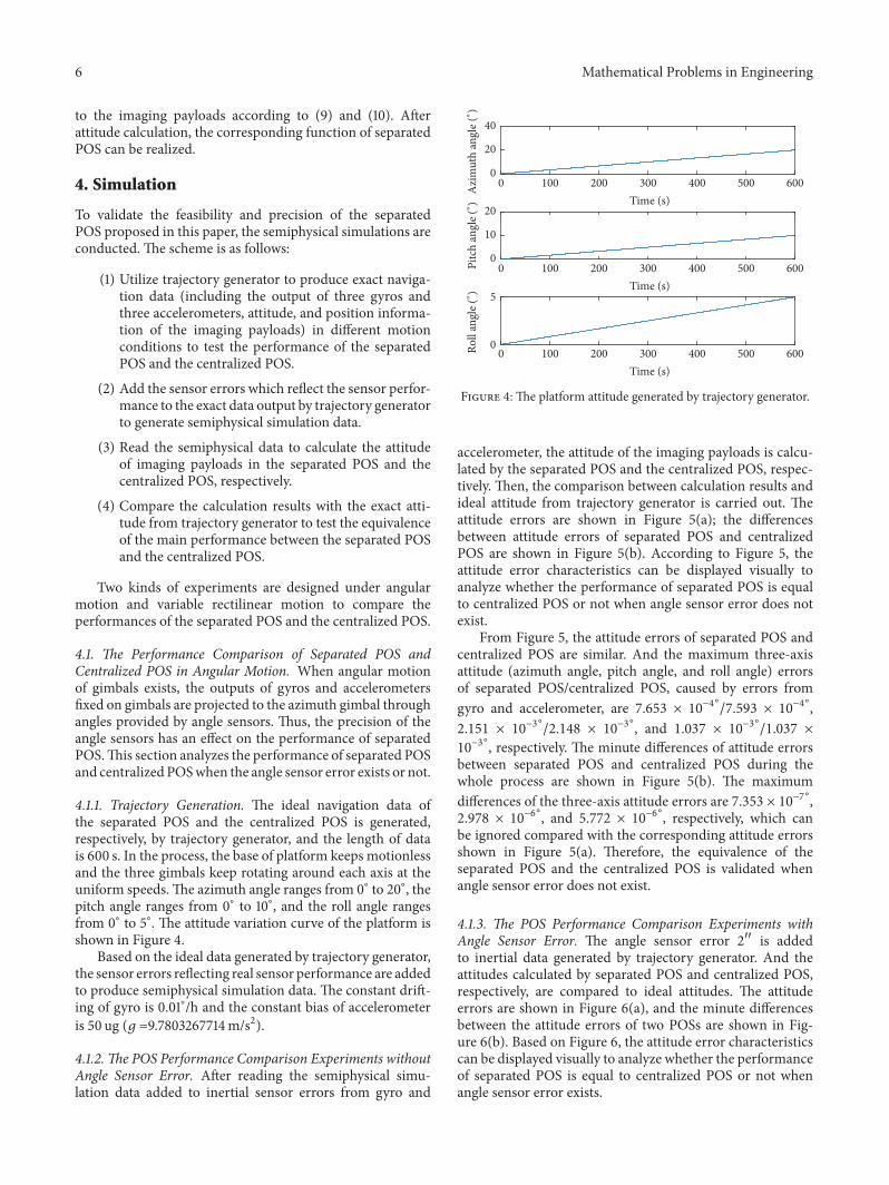
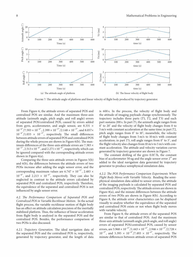

Hindawiwwwhindawicom Volume 2018
MathematicsJournal of
Hindawiwwwhindawicom Volume 2018
Mathematical Problems in Engineering
Applied MathematicsJournal of
Hindawiwwwhindawicom Volume 2018
Probability and StatisticsHindawiwwwhindawicom Volume 2018
Journal of
Hindawiwwwhindawicom Volume 2018
Mathematical PhysicsAdvances in
Complex AnalysisJournal of
Hindawiwwwhindawicom Volume 2018
OptimizationJournal of
Hindawiwwwhindawicom Volume 2018
Hindawiwwwhindawicom Volume 2018
Engineering Mathematics
International Journal of
Hindawiwwwhindawicom Volume 2018
Operations ResearchAdvances in
Journal of
Hindawiwwwhindawicom Volume 2018
Function SpacesAbstract and Applied AnalysisHindawiwwwhindawicom Volume 2018
International Journal of Mathematics and Mathematical Sciences
Hindawiwwwhindawicom Volume 2018
Hindawi Publishing Corporation httpwwwhindawicom Volume 2013Hindawiwwwhindawicom
The Scientific World Journal
Volume 2018
Hindawiwwwhindawicom Volume 2018Volume 2018
Numerical AnalysisNumerical AnalysisNumerical AnalysisNumerical AnalysisNumerical AnalysisNumerical AnalysisNumerical AnalysisNumerical AnalysisNumerical AnalysisNumerical AnalysisNumerical AnalysisNumerical AnalysisAdvances inAdvances in Discrete Dynamics in
Nature and SocietyHindawiwwwhindawicom Volume 2018
Hindawiwwwhindawicom
Dierential EquationsInternational Journal of
Volume 2018
Hindawiwwwhindawicom Volume 2018
Decision SciencesAdvances in
Hindawiwwwhindawicom Volume 2018
AnalysisInternational Journal of
Hindawiwwwhindawicom Volume 2018
Stochastic AnalysisInternational Journal of
Submit your manuscripts atwwwhindawicom