a power center 8.1 getting start
TRANSCRIPT

8/6/2019 a Power Center 8.1 Getting Start
http://slidepdf.com/reader/full/a-power-center-81-getting-start 1/158
Getting Started
Informatica PowerCenter ® (Version 8.1.1)

8/6/2019 a Power Center 8.1 Getting Start
http://slidepdf.com/reader/full/a-power-center-81-getting-start 2/158
Informatica PowerCenter Getting StartedVersion 8.1.1September 2006
Copyright (c) 1998–2006 Informatica Corporation. All rights reserved. Printed in the USA.
This software and documentation contain proprietary information of Informatica Corporation and are provided under a license agreement containingrestrictions on use and disclosure and are also protected by copyright law. Reverse engineering of the software is prohibited. No part of this document may bereproduced or transmitted in any form, by any means (electronic, photocopying, recording or otherwise) without prior consent of Informatica Corporation.
Use, duplication, or disclosure of the Software by the U.S. Government is subject to the restrictions set forth in the applicable software license agreement and asprovided in DFARS 227.7202-1(a) and 227.7702-3(a) (1995), DFARS 252.227-7013(c)(1)(ii) (OCT 1988), FAR 12.212(a) (1995), FAR 52.227-19, or FAR 52.227-14 (ALT III), as applicable. The information in this document is subject to change wi thout notice. If you find any problems in the documentation, please report them to us in writing.Informatica Corporation does not warrant that this documentation is error free.
Informatica, PowerCenter, PowerCenterRT, PowerCenter Connect, PowerCenter Data Analyzer, PowerMart, SuperGlue, Metadata Manager, Informatica DataQuality and Informatica Data Explorer are trademarks or registered trademarks of Informatica Corporation in the United States and in jurisdictions throughoutthe world. All other company and product names may be trade names or trademarks of their respective owners.
Portions of this software and/or documentation are subject to copyright held by third parties, including without l imitation: Copyright DataDirect Technologies,1999-2002. All rights reserved. Copyright © Sun Microsystems. All Rights Reserved. Copyright © RSA Security Inc. All Rights Reserved. Copyright © OrdinalTechnology Corp. A ll Rights Reserved.
Informatica PowerCenter products contain ACE (TM) software copyrighted by Douglas C. Schmidt and his research group at Washington University andUniversity of California, Irvine, Copyright (c) 1993-2002, all rights reserved.
Portions of this software contain copyrighted material from The JBoss Group, LLC. Your right to use such materials is set forth in the GNU Lesser GeneralPublic License Agreement, which may be found at http://www.opensource.org/licenses/lgpl-license.php. The JBoss materials are provided free of charge by Informatica, “as-is”, without warranty of any kind, either express or implied, including but not limited to the implied warranties of merchantability and fitnessfor a particular purpose.
Portions of this software contain copyrighted material from Meta Integration Technology, Inc. Meta Integration® is a registered trademark of Meta IntegrationTechnology, Inc.
This product includes software developed by the Apache Software Foundation (http://www.apache.org/). The Apache Software is Copyright (c) 1999-2005 The Apache Software Foundation. All rights reserved.
This product includes software developed by the OpenSSL Project for use in the OpenSSL Toolkit and redistribution of this software is subject to terms availableat http://www.openssl.org. Copyright 1998-2003 The OpenSSL Project. All Rights Reserved.
The zlib library included with th is software is Copyright (c) 1995-2003 Jean-loup Gailly and Mark Adler.
The Curl license provided with this Software is Copyright 1996-2004, Daniel Stenberg, <[email protected]>. All Rights Reserved.
The PCRE library included with this software is Copyright (c) 1997-2001 University of Cambridge Regular expression support is provided by the PCRE library package, which is open source software, written by Philip Hazel. The source for this library may be found at ftp://ftp.csx.cam.ac.uk/pub/software/programming/pcre.
InstallAnywhere is Copyright 2005 Zero G Software, Inc. All Rights Reserved.
Portions of the Software are Copyright (c) 1998-2005 The OpenLDAP Foundation. All rights reserved. Redistribution and use in source and binary forms, with
or without modification, are permitted only as authorized by the OpenLDAP Public License, available at h ttp://www.openldap.org/software/release/license.html.This Software is protected by U.S. Patent Numbers 6,208,990; 6,044,374; 6 ,014,670; 6,032,158; 5,794,246; 6,339,775 and other U.S. Patents Pending.
DISCLAIMER: Informatica Corporation provides this documentation “as is” without warranty of any kind, either express or implied,including, but not limited to, the implied warranties of non-infringement, merchantability, or use for a particular purpose. The information provided in thisdocumentation may include technical inaccuracies or typographical errors. Informatica could make improvements and/or changes in the products described inthis documentation at any time without notice.

8/6/2019 a Power Center 8.1 Getting Start
http://slidepdf.com/reader/full/a-power-center-81-getting-start 3/158
ii i
Table of Contents
Preface . . . . . . . . . . . . . . . . . . . . . . . . . . . . . . . . . . . . . . . . . . . . . . . . .vii
About This Book . . . . . . . . . . . . . . . . . . . . . . . . . . . . . . . . . . . . . . . . . . . viiiDocument Conventions . . . . . . . . . . . . . . . . . . . . . . . . . . . . . . . . . . . viii
Other Informatica Resources . . . . . . . . . . . . . . . . . . . . . . . . . . . . . . . . . . . . ixVisiting Informatica Customer Portal . . . . . . . . . . . . . . . . . . . . . . . . . . ixVisiting the Informatica Web Site . . . . . . . . . . . . . . . . . . . . . . . . . . . . . ixVisiting the Informatica Developer Network . . . . . . . . . . . . . . . . . . . . . ix
Visiting the Informatica Knowledge Base . . . . . . . . . . . . . . . . . . . . . . . . ixObtaining Technical Support . . . . . . . . . . . . . . . . . . . . . . . . . . . . . . . . ix
Chapter 1: Product Overview . . . . . . . . . . . . . . . . . . . . . . . . . . . . . . . . 1
Introduction . . . . . . . . . . . . . . . . . . . . . . . . . . . . . . . . . . . . . . . . . . . . . . . . 2Sources . . . . . . . . . . . . . . . . . . . . . . . . . . . . . . . . . . . . . . . . . . . . . . . . . 3
Targets . . . . . . . . . . . . . . . . . . . . . . . . . . . . . . . . . . . . . . . . . . . . . . . . . 4PowerCenter Domain . . . . . . . . . . . . . . . . . . . . . . . . . . . . . . . . . . . . . . . . . . 5
Service Manager . . . . . . . . . . . . . . . . . . . . . . . . . . . . . . . . . . . . . . . . . . . 6 Application Services . . . . . . . . . . . . . . . . . . . . . . . . . . . . . . . . . . . . . . . . 6
PowerCenter Repository . . . . . . . . . . . . . . . . . . . . . . . . . . . . . . . . . . . . . . . . 7 Administration Console . . . . . . . . . . . . . . . . . . . . . . . . . . . . . . . . . . . . . . . . 8PowerCenter Client . . . . . . . . . . . . . . . . . . . . . . . . . . . . . . . . . . . . . . . . . . 10
PowerCenter Designer . . . . . . . . . . . . . . . . . . . . . . . . . . . . . . . . . . . . . 10Data Stencil . . . . . . . . . . . . . . . . . . . . . . . . . . . . . . . . . . . . . . . . . . . . . 11Repository Manager . . . . . . . . . . . . . . . . . . . . . . . . . . . . . . . . . . . . . . . 12
Workflow Manager. . . . . . . . . . . . . . . . . . . . . . . . . . . . . . . . . . . . . . . . 14 Workflow Monitor . . . . . . . . . . . . . . . . . . . . . . . . . . . . . . . . . . . . . . . . 15
Repository Service . . . . . . . . . . . . . . . . . . . . . . . . . . . . . . . . . . . . . . . . . . . 17Integration Service . . . . . . . . . . . . . . . . . . . . . . . . . . . . . . . . . . . . . . . . . . . 18
Web Services Hub . . . . . . . . . . . . . . . . . . . . . . . . . . . . . . . . . . . . . . . . . . . 19Data Analyzer . . . . . . . . . . . . . . . . . . . . . . . . . . . . . . . . . . . . . . . . . . . . . . 20
Data Analyzer Components . . . . . . . . . . . . . . . . . . . . . . . . . . . . . . . . . 20Metadata Manager . . . . . . . . . . . . . . . . . . . . . . . . . . . . . . . . . . . . . . . . . . . 22
Metadata Manager Components . . . . . . . . . . . . . . . . . . . . . . . . . . . . . . 22
PowerCenter Repository Reports . . . . . . . . . . . . . . . . . . . . . . . . . . . . . . . . . 24

8/6/2019 a Power Center 8.1 Getting Start
http://slidepdf.com/reader/full/a-power-center-81-getting-start 4/158
iv Table of Contents
Chapter 2: Before You Begin . . . . . . . . . . . . . . . . . . . . . . . . . . . . . . . . 25
Overview . . . . . . . . . . . . . . . . . . . . . . . . . . . . . . . . . . . . . . . . . . . . . . . . . .26Getting Started . . . . . . . . . . . . . . . . . . . . . . . . . . . . . . . . . . . . . . . . . .26
Using the PowerCenter Client in the Tutorial . . . . . . . . . . . . . . . . . . . . . 26Connecting to Databases . . . . . . . . . . . . . . . . . . . . . . . . . . . . . . . . . . . . . . . 28
Chapter 3: Tutorial Lesson 1 . . . . . . . . . . . . . . . . . . . . . . . . . . . . . . . . 31
Creating Repository Users and Groups . . . . . . . . . . . . . . . . . . . . . . . . . . . . . 32Connecting to the Repository . . . . . . . . . . . . . . . . . . . . . . . . . . . . . . . . 32Creating a Group . . . . . . . . . . . . . . . . . . . . . . . . . . . . . . . . . . . . . . . . . 34
Assigning Privileges to a Group . . . . . . . . . . . . . . . . . . . . . . . . . . . . . . . 35Creating a User . . . . . . . . . . . . . . . . . . . . . . . . . . . . . . . . . . . . . . . . . . 36
Creating a Folder . . . . . . . . . . . . . . . . . . . . . . . . . . . . . . . . . . . . . . . . . . . . 38Folder Permissions . . . . . . . . . . . . . . . . . . . . . . . . . . . . . . . . . . . . . . . . 38Creating Folders in This Tutorial. . . . . . . . . . . . . . . . . . . . . . . . . . . . . .38
Creating Source Tables . . . . . . . . . . . . . . . . . . . . . . . . . . . . . . . . . . . . . . . . 40 What Comes Next . . . . . . . . . . . . . . . . . . . . . . . . . . . . . . . . . . . . . . . . . . . 43
Chapter 4: Tutorial Lesson 2 . . . . . . . . . . . . . . . . . . . . . . . . . . . . . . . . 45
Creating Source Definitions . . . . . . . . . . . . . . . . . . . . . . . . . . . . . . . . . . . . 46Viewing Source Definitions. . . . . . . . . . . . . . . . . . . . . . . . . . . . . . . . . . 48
Creating Target Defin itions and Target Tables . . . . . . . . . . . . . . . . . . . . . . .51
Creating Target Definitions. . . . . . . . . . . . . . . . . . . . . . . . . . . . . . . . . .51Creating Target Tables . . . . . . . . . . . . . . . . . . . . . . . . . . . . . . . . . . . . . 53
What Comes Next . . . . . . . . . . . . . . . . . . . . . . . . . . . . . . . . . . . . . . . . . . . 55
Chapter 5: Tutorial Lesson 3 . . . . . . . . . . . . . . . . . . . . . . . . . . . . . . . . 57
Creating a Pass-Through Mapping . . . . . . . . . . . . . . . . . . . . . . . . . . . . . . . . 58
Creating a Mapping . . . . . . . . . . . . . . . . . . . . . . . . . . . . . . . . . . . . . . . 59Connecting Transformations . . . . . . . . . . . . . . . . . . . . . . . . . . . . . . . . . 60
Creating Sessions and Workflows . . . . . . . . . . . . . . . . . . . . . . . . . . . . . . . . . 62Configuring Database Connections in the Workflow Manager . . . . . . . . . 63Creating a Reusable Session . . . . . . . . . . . . . . . . . . . . . . . . . . . . . . . . . 65Creating a Workflow. . . . . . . . . . . . . . . . . . . . . . . . . . . . . . . . . . . . . . . 68
Running and Monitoring Workflows . . . . . . . . . . . . . . . . . . . . . . . . . . . . . .71Opening the Workflow Monitor . . . . . . . . . . . . . . . . . . . . . . . . . . . . . . 71Running the Workflow . . . . . . . . . . . . . . . . . . . . . . . . . . . . . . . . . . . . . 71

8/6/2019 a Power Center 8.1 Getting Start
http://slidepdf.com/reader/full/a-power-center-81-getting-start 5/158
Table of Contents v
What Comes Next . . . . . . . . . . . . . . . . . . . . . . . . . . . . . . . . . . . . . . . . . . . 74
Chapter 6: Tutorial Lesson 4 . . . . . . . . . . . . . . . . . . . . . . . . . . . . . . . . 75
Using Transformations . . . . . . . . . . . . . . . . . . . . . . . . . . . . . . . . . . . . . . . . 76Creating a New Target Definition and Target . . . . . . . . . . . . . . . . . . . . . . . . 78
Creating a Target Definition . . . . . . . . . . . . . . . . . . . . . . . . . . . . . . . . . 78Creating a Target Table . . . . . . . . . . . . . . . . . . . . . . . . . . . . . . . . . . . . 81
Creating a Mapping with Aggregate Values . . . . . . . . . . . . . . . . . . . . . . . . . 82Creating a Mapping with T_ITEM_SUMMARY . . . . . . . . . . . . . . . . . . 82Creating an Aggregator Transformation . . . . . . . . . . . . . . . . . . . . . . . . . 82Creating an Expression Transformation . . . . . . . . . . . . . . . . . . . . . . . . . 87Creating a Lookup Transformation . . . . . . . . . . . . . . . . . . . . . . . . . . . . 88Connecting the Target . . . . . . . . . . . . . . . . . . . . . . . . . . . . . . . . . . . . . 90
Designer Tips . . . . . . . . . . . . . . . . . . . . . . . . . . . . . . . . . . . . . . . . . . . . . . 92Using the Overview Window . . . . . . . . . . . . . . . . . . . . . . . . . . . . . . . . 92
Arranging Transformations . . . . . . . . . . . . . . . . . . . . . . . . . . . . . . . . . . 93
Creating a Session and Workflow . . . . . . . . . . . . . . . . . . . . . . . . . . . . . . . . 94Creating the Session . . . . . . . . . . . . . . . . . . . . . . . . . . . . . . . . . . . . . . . 94Creating the Workflow . . . . . . . . . . . . . . . . . . . . . . . . . . . . . . . . . . . . . 95Running the Workflow . . . . . . . . . . . . . . . . . . . . . . . . . . . . . . . . . . . . . 96Viewing the Logs . . . . . . . . . . . . . . . . . . . . . . . . . . . . . . . . . . . . . . . . . 98
What Comes Next . . . . . . . . . . . . . . . . . . . . . . . . . . . . . . . . . . . . . . . . . . 100
Chapter 7: Tutorial Lesson 5 . . . . . . . . . . . . . . . . . . . . . . . . . . . . . . . 101
Creating a Mapping with Fact and Dimension Tables . . . . . . . . . . . . . . . . . 102Creating Targets. . . . . . . . . . . . . . . . . . . . . . . . . . . . . . . . . . . . . . . . . 102Creating the Mapping . . . . . . . . . . . . . . . . . . . . . . . . . . . . . . . . . . . . 104Creating a Filter Transformation . . . . . . . . . . . . . . . . . . . . . . . . . . . . . 106Creating a Sequence Generator Transformation . . . . . . . . . . . . . . . . . . 107Creating a Stored Procedure Transformation . . . . . . . . . . . . . . . . . . . . 109Completing the Mapping . . . . . . . . . . . . . . . . . . . . . . . . . . . . . . . . . . 111
Creating a Workflow . . . . . . . . . . . . . . . . . . . . . . . . . . . . . . . . . . . . . . . . 113Creating the Workflow . . . . . . . . . . . . . . . . . . . . . . . . . . . . . . . . . . . . 113
Adding a Non-Reusable Session . . . . . . . . . . . . . . . . . . . . . . . . . . . . . 113Defining a Link Condition . . . . . . . . . . . . . . . . . . . . . . . . . . . . . . . . . 114
Running the Workflow . . . . . . . . . . . . . . . . . . . . . . . . . . . . . . . . . . . . 117 What Comes Next . . . . . . . . . . . . . . . . . . . . . . . . . . . . . . . . . . . . . . . . . . 118

8/6/2019 a Power Center 8.1 Getting Start
http://slidepdf.com/reader/full/a-power-center-81-getting-start 6/158
vi Table of Contents
Chapter 8: Tutorial Lesson 6 . . . . . . . . . . . . . . . . . . . . . . . . . . . . . . . 119
Using XML Files . . . . . . . . . . . . . . . . . . . . . . . . . . . . . . . . . . . . . . . . . . . 120Creating the XML Source . . . . . . . . . . . . . . . . . . . . . . . . . . . . . . . . . . . . . 121
Importing the XML Source . . . . . . . . . . . . . . . . . . . . . . . . . . . . . . . . . 121Editing the XML Definition . . . . . . . . . . . . . . . . . . . . . . . . . . . . . . . . 123
Creating the Target . . . . . . . . . . . . . . . . . . . . . . . . . . . . . . . . . . . . . . . . . .128Creating a Mapping with XML Sources and Targets . . . . . . . . . . . . . . . . . . 131
Creating an Expression Transformation . . . . . . . . . . . . . . . . . . . . . . . . 131Creating Router Transformations . . . . . . . . . . . . . . . . . . . . . . . . . . . . . 132Completing the Mapping . . . . . . . . . . . . . . . . . . . . . . . . . . . . . . . . . . 136
Creating a Workflow . . . . . . . . . . . . . . . . . . . . . . . . . . . . . . . . . . . . . . . . . 138
Appendix A: Naming Conventions . . . . . . . . . . . . . . . . . . . . . . . . . . 145
Suggested Naming Conventions. . . . . . . . . . . . . . . . . . . . . . . . . . . . . . . . . 146Transformations . . . . . . . . . . . . . . . . . . . . . . . . . . . . . . . . . . . . . . . . . 146Targets . . . . . . . . . . . . . . . . . . . . . . . . . . . . . . . . . . . . . . . . . . . . . . . . 147Mappings. . . . . . . . . . . . . . . . . . . . . . . . . . . . . . . . . . . . . . . . . . . . . . 147Mapplets . . . . . . . . . . . . . . . . . . . . . . . . . . . . . . . . . . . . . . . . . . . . . . 147Sessions . . . . . . . . . . . . . . . . . . . . . . . . . . . . . . . . . . . . . . . . . . . . . . . 147
Worklets . . . . . . . . . . . . . . . . . . . . . . . . . . . . . . . . . . . . . . . . . . . . . . 147 Workflows . . . . . . . . . . . . . . . . . . . . . . . . . . . . . . . . . . . . . . . . . . . . . 147

8/6/2019 a Power Center 8.1 Getting Start
http://slidepdf.com/reader/full/a-power-center-81-getting-start 7/158
vii
Preface
Welcome to PowerCenter, the Informatica software product that delivers an open, scalabledata integration solution addressing the complete life cycle for all data integration projects
including data warehouses, data migration, data synchronization, and information hubs.PowerCenter combines the latest technology enhancements for reliably managing datarepositories and delivering information resources in a timely, usable, and efficient manner.
The PowerCenter repository coordinates and drives a variety of core functions, includingextracting, transforming, loading, and managing data. The Integration Service can extractlarge volumes of data from multiple platforms, handle complex transformations on the data,and support high-speed loads. PowerCenter can simplify and accelerate the process of building a comprehensive data warehouse from disparate data sources.

8/6/2019 a Power Center 8.1 Getting Start
http://slidepdf.com/reader/full/a-power-center-81-getting-start 8/158
viii Preface
About This Book
Getting Started is written for the developers and software engineers who are responsible forimplementing a data warehouse. It provides a tutorial to help first-time users learn how to usePowerCenter. Getting Started assumes you have knowledge of your operating systems,relational database concepts, and the database engines, flat files, or mainframe systems in yourenvironment. The guide also assumes you are familiar with the interface requirements foryour supporting applications.
The material in this book is available for online use.
Document ConventionsThis guide uses the following formatting conventions:
If you see… It means…
italicized text The word or set of words are especially emphasized.
boldfaced text Emphasized subjects.
italicized monospaced text This is the variable name for a value you enter as part of anoperating system command. This is generic text that should bereplaced with user-supplied values.
Note: The following paragraph provides additional facts.
Tip: The following paragraph provides suggested uses.
Warning: The following paragraph notes situations where you can overwriteor corrupt data, unless you follow the specified procedure.
monospaced text This is a code example.
bold monospaced text This is an operating system command you enter from a prompt torun a task.

8/6/2019 a Power Center 8.1 Getting Start
http://slidepdf.com/reader/full/a-power-center-81-getting-start 9/158
Preface ix
Other Informatica Resources
In addition to the product manuals, Informatica provides these other resources:
♦ Informatica Customer Portal♦ Informatica web site♦ Informatica Developer Network ♦ Informatica Knowledge Base♦ Informatica Technical Support
Visiting Informatica Customer Portal As an Informatica customer, you can access the Informatica Customer Portal site athttp://my.informatica.com. The site contains product information, user group information,newsletters, access to the Informatica customer support case management system (ATLAS),the Informatica Knowledge Base, and access to the Informatica user community.
Visiting the Informatica Web Site You can access the Informatica corporate web site at http://www.informatica.com. The sitecontains information about Informatica, its background, upcoming events, and sales offices.
You will also find product and partner information. The services area of the site includesimportant information about technical support, training and education, and implementationservices.
Visiting the Informatica Developer Network You can access the Informatica Developer Network at http://devnet.informatica.com. TheInformatica Developer Network is a web-based forum for third-party software developers.The site contains information about how to create, market, and support customer-orientedadd-on solutions based on interoperability interfaces for Informatica products.
Visiting the Informatica Knowledge Base
As an Informatica customer, you can access the Informatica Knowledge Base athttp://my.informatica.com. Use the Knowledge Base to search for documented solutions toknown technical issues about Informatica products. You can also find answers to frequently asked questions, technical white papers, and technical tips.
Obtaining Technical SupportThere are many ways to access Informatica Technical Support. You can contact a Technical
Support Center by using the telephone numbers listed the following table, you can sendemail, or you can use the WebSupport Service.

8/6/2019 a Power Center 8.1 Getting Start
http://slidepdf.com/reader/full/a-power-center-81-getting-start 10/158
x Preface
Use the following email addresses to contact Informatica Technical Support:
♦ [email protected] for technical inquiries♦ [email protected] for general customer service requests
WebSupport requires a user name and password. You can request a user name and password athttp://my.informatica.com.
North America / South America Europe / Middle East / Africa Asia / Austral ia
Informatica Corporation
Headquarters100 Cardinal WayRedwood City, California94063United States
Toll Free877 463 2435
Standard Rate
United States: 650 385 5800
Informatica Software Ltd .6 Waltham ParkWaltham Road, White WalthamMaidenhead, BerkshireSL6 3TNUnited Kingdom
Toll Free00 800 4632 4357
Standard Rate
Belgium: +32 15 281 702France: +33 1 41 38 92 26Germany: +49 1805 702 702Netherlands: +31 306 022 797United Kingdom: +44 1628 511 445
Informatica Business Solutions
Pvt. Ltd.Diamond DistrictTower B, 3rd Floor150 Airport RoadBangalore 560 008India
Toll FreeAustralia: 00 11 800 4632 4357Singapore: 001 800 4632 4357
Standard Rate
India: +91 80 4112 5738

8/6/2019 a Power Center 8.1 Getting Start
http://slidepdf.com/reader/full/a-power-center-81-getting-start 11/158
1
C h a p t e r 1
Product Overview
This chapter includes the following topics:
♦ Introduction, 2♦ PowerCenter Domain, 5♦ PowerCenter Repository, 7♦ Administration Console, 8♦ PowerCenter Client, 10♦ Repository Service, 17♦ Integration Service, 18♦ Web Services Hub, 19♦ Data Analyzer, 20♦ Metadata Manager, 22♦ PowerCenter Repository Reports, 24

8/6/2019 a Power Center 8.1 Getting Start
http://slidepdf.com/reader/full/a-power-center-81-getting-start 12/158
2 Ch apter 1: Pro duct Overview
Introduction
PowerCenter provides an environment that allows you to load data into a centralized locat ion,such as a data warehouse or operational data store (ODS). You can extract data from multiple
sources, transform the data according to business logic you build in the client application, andload the transformed data into file and relational targets.
PowerCenter also provides the ability to view and analyze business information and browseand analyze metadata from disparate metadata repositories.
PowerCenter includes the following components:
♦ PowerCenter domain. The Power Center domain is the primary unit for management and
administration within PowerCenter. The Service Manager runs on a PowerCenter domain.The Service Manager supports the domain and the application services. Applicationservices represent server-based functionality and include the Repository Service,Integration Service, Web Services Hub, and SAP BW Service. For more information, see“PowerCenter Domain” on page 5.
♦ PowerCenter repository. The PowerCenter repository resides in a relational database. Therepository database tables contain the instructions required to extract, transform, and loaddata. For more information, see“PowerCenter Repository” on page 7.
♦ Administration Console. The Administration Console is a web-based administration toolyou can use to administer the PowerCenter domain. For more information, see“Administration Console” on page 8.
♦ PowerCenter Client. The PowerCenter Client is used to manage users, define sources andtargets, build mappings and mapplets with the transformation logic, and create workflowsto run the mapping logic. The PowerCenter Client connects to the repository through theRepository Service to modify repository metadata. It connects to the Integration Service to
start workflows. For more information, see“PowerCenter Client” on page 10.♦ Repository Service.The Repository Service accepts requests from the PowerCenter Client
to create and modify repository metadata and accepts requests from the Integration Servicefor metadata when a workflow runs. For more information, see“Repository Service” onpage 17.
♦ Integration Service. The Integration Service extracts data from sources and loads data totargets. For more information, see“Integration Service” on page 18.
♦ Web Services Hub. Web Services Hub is a gateway that exposes PowerCenter functionality to external clients through web services. For more information, see“Web Services Hub”on page 19.
♦ SAP BW Service. The SAP BW Service extracts data from and loads data to SAP BW.♦ Data Analyzer. Data Analyzer provides a framework to perform business analytics on
corporate data. With Data Analyzer, you can extract, filter, format, and analyze corporateinformation from data stored in a data warehouse, operational data store, or other data
storage models. For more information, see“Data Analyzer” on page 20.♦ Metadata Manager. Metadata Manager is a metadata management tool that you can use to
browse and analyze metadata from disparate metadata repositories. Metadata Manager

8/6/2019 a Power Center 8.1 Getting Start
http://slidepdf.com/reader/full/a-power-center-81-getting-start 13/158
Introduction 3
helps you understand and manage how information and processes are derived, thefundamental relationships between them, and how they are used. For more information,see “Metadata Manager” on page 22.
♦ PowerCenter Repository Reports. PowerCenter Repository Reports are a set of prepackaged Data Analyzer reports and dashboards to help you analyze and managePowerCenter metadata. For more information, see“PowerCenter Repository Reports” onpage 24.
Figure 1-1 shows the PowerCenter components:
For more information about Data Analyzer and Metadata Manager components, see“Data Analyzer” on page 20and “Metadata Manager” on page 22.
SourcesPowerCenter accesses the following sources:
♦ Relational. Oracle, Sybase ASE, Informix, IBM DB2, Microsoft SQL Server, andTeradata.
♦ File. Fixed and delimited flat file, COBOL file, XML file, and web log.♦ Application. You can purchase additional PowerCenter Connect products to access
business sources such as Hyperion Essbase, IBM MQSeries, IBM DB2 OLAP Server, JMS,Microsoft Message Queue, PeopleSoft, SAP NetWeaver, SAS, Siebel, TIBCO,
webMethods, and Salesforce.com.♦ Mainframe. You can purchase PowerExchange to access source data from mainframe
databases such as Adabas, Datacom, IBM DB2 OS/390, IBM DB2 OS/400, IDMS,IDMS-X, IMS, and VSAM.
♦ Other. Microsoft Excel, Microsoft Access, and external web services.
For more information about sources, see “Working with Sources” in theDesigner Guide .
Figure 1-1. PowerCenter Components
Service Manager
SourcesRelational Flat Files
Web ServicesApplicationsMainframe
Other
TargetsRelational Flat Files
Web ServicesApplicationsMainframe
Other
AdministrationConsole
PowerCenter Client ToolsDesigner
Workflow Manager Workflow Monitor Repository Manager
Repository
RepositoryService
IntegrationService
Web ServicesHub
SAP BW
Service

8/6/2019 a Power Center 8.1 Getting Start
http://slidepdf.com/reader/full/a-power-center-81-getting-start 14/158
4 Ch apter 1: Pro duct Overview
TargetsPowerCenter can load data into the following targets:
♦ Relational. Oracle, Sybase ASE, Sybase IQ, Informix, IBM DB2, Microsoft SQL Server,and Teradata.
♦ File. Fixed and delimited flat file and XML.♦ Application. You can purchase additional PowerCenter Connect products to load data into
business sources such as Hyperion Essbase, IBM MQSeries, IBM DB2 OLAP Server, JMS,Microsoft Message Queue, mySAP, PeopleSoft EPM, SAP BW, SAS, Siebel, TIBCO, and
webMethods.♦ Mainframe. You can purchase PowerExchange to load data into mainframe databases such
as IBM DB2 OS/390, IBM DB2 OS/400, and VSAM.♦ Other. Microsoft Access and external web services.
You can load data into targets using ODBC or native drivers, FTP, or external loaders.
For more information about targets, see “Working with Targets” in theDesigner Guide .

8/6/2019 a Power Center 8.1 Getting Start
http://slidepdf.com/reader/full/a-power-center-81-getting-start 15/158
PowerCenter Domain 5
PowerCenter Domain
PowerCenter has a service-oriented architecture that provides the ability to scale services andshare resources across multiple machines. PowerCenter provides the PowerCenter domain to
support the administration of the PowerCenter services. A domain is the primary unit formanagement and administration of services in PowerCenter.
A domain contains the following components:
♦ One or more nodes. A node is the logical representation of a machine in a domain. A domain may contain more than one node. The node that hosts the domain is the mastergateway for the domain. You can add other machines as nodes in the domain andconfigure the nodes to run application services, such as the Integration Service or
Repository Service. All service requests from other nodes in the domain go through themaster gateway.
A nodes runs service processes, which is the runtime representation of an applicationservice running on a node.
♦ Service Manager. The Service Manager is built in to the domain to support the domainand the application services. The Service Manager runs on each node in the domain. TheService Manager starts and runs the application services on a machine. For more
information, see“Service Manager” on page 6.♦ Application services. A group of services that represent PowerCenter server-based
functionality. The application services that run on each node in the domain depend on the way you configure the node and the application service. For more information, see“Application Services” on page 6.
You can use the PowerCenter Administration Console to manage the domain. For moreinformation about the Administration Console, see“Administration Console” on page 8.
If you have the high availability option, you can scale services and eliminate single points of failure for services. The Service Manager and application services can continue runningdespite temporary network or hardware failures. High availability includes resilience, failover,and recovery for services and tasks in a domain. For more information about high availability,see “Managing High Availability” in the Administrator Guide .
Figure 1-2 shows a sample domain with three nodes:
This domain has a master gateway on Node 1. Node 2 runs an Integration Service and Node3 runs the Repository Service.
Figure 1-2. Domain with Three Nodes
Service Manager
Node 1 (Master Gateway) Node 2 Node 3
Repository ServiceIntegration Service
Service ManagerService Manager

8/6/2019 a Power Center 8.1 Getting Start
http://slidepdf.com/reader/full/a-power-center-81-getting-start 16/158
6 Ch apter 1: Pro duct Overview
Service Manager The Service Manager is built in to the domain and supports the domain and the applicationservices. The Service Manager performs the following functions:
♦ Alerts. Provides notifications about domain and service events.♦ Authentication. Authenticates user requests from the Administration Console and from
infacmd .♦ Authorization. Authorizes user requests for services. Requests can come from the
Administration Console or frominfacmd.♦ Domain configuration. Manages domain configuration metadata.♦ Node configuration. Manages node configuration metadata.
♦ Licensing. Registers license information and verifies license information when you runapplication services.
♦ Logging. Provides accumulated log events from each service in the domain. You can view logs in the Administration Console and Workflow Monitor.
For more information about the Service Manager, see“Service Manager” on page 6.
Application Services When you install PowerCenter Services, the installation program installs the followingapplication services:
♦ Repository Service. Manages connections to the PowerCenter repository. For moreinformation, see“Repository Service” on page 17.
♦ Integration Service. Runs sessions and workflows. For more information , see“IntegrationService” on page 18.
♦ Web Services Hub. Exposes PowerCenter functionality to external clients through webservices. For more information, see“Web Services Hub” on page 19.
♦ SAP BW Service.Listens for RFC requests from SAP NetWeaver BW and initiates workflows to extract from or load to SAP BW.

8/6/2019 a Power Center 8.1 Getting Start
http://slidepdf.com/reader/full/a-power-center-81-getting-start 17/158
PowerCenter Repository 7
PowerCenter Repository
The PowerCenter repository resides in a relational database. The repository database tablescontain the instructions required to extract, transform, and load data and store administrative
information such as user names, passwords, permissions, and privileges. PowerCenterapplications access the repository through the Repository Service.
You administer the repository using the Repository Manager client tool, the PowerCenter Administration Console, and command line programs.
You can develop global and local repositories to share metadata:
♦ Global repository. The global repository is the hub of the repository domain. Use theglobal repository to store common objects that multiple developers can use throughshortcuts. These objects may include operational or Application source definitions,reusable transformations, mapplets, and mappings.
♦ Local repositories. A local repository is any repository within the domain that is not theglobal repository. Use local repositories for development. From a local repository, you cancreate shortcuts to objects in shared folders in the global repository. These objects includesource definitions, common dimensions and lookups, and enterprise standardtransformations. You can also create copies of objects in non-shared folders.
PowerCenter supports versioned repositories. A versioned repository can store mul tipleversions of an object. PowerCenter version control allows you to efficiently develop, test, anddeploy metadata into production.
You can view repository metadata in the Repository Manager. The Informatica MetadataExchange (MX) provides a set of relational views that allow easy SQL access to thePowerCenter metadata repository. For more information, see “Using Metadata Exchange(MX) Views” in theRepository Guide . You can also view metadata using PowerCenter
Repository Reports and Data Analyzer.

8/6/2019 a Power Center 8.1 Getting Start
http://slidepdf.com/reader/full/a-power-center-81-getting-start 18/158

8/6/2019 a Power Center 8.1 Getting Start
http://slidepdf.com/reader/full/a-power-center-81-getting-start 19/158
Administration Console 9
Figure 1-3 shows the Administration Console:
Figure 1-3. PowerCenter Administration Console

8/6/2019 a Power Center 8.1 Getting Start
http://slidepdf.com/reader/full/a-power-center-81-getting-start 20/158
10 Ch ap ter 1: P ro du ct Ove rvie w
PowerCenter Client
The PowerCenter Client consists of the following applications that you use to manage therepository, design mappings, mapplets, and create sessions to load the data:
♦ Designer. Use the Designer to create mappings that contain transformation instructionsfor the Integration Service. For more information about the Designer, see“PowerCenterDesigner” on page 10.
♦ Data Stencil. Use the Data Stencil to create mapping template that can be used to generatemultiple mappings.
♦ Repository Manager. Use the Repository Manager to create repository users and groups,assign privileges and permissions, and manage folders and locks. For more informationabout the Repository Manager, see“Repository Manager” on page 12.
♦ Workflow Manager. Use the Workflow Manager to create, schedule, and run workflows. A workflow is a set of instructions that describes how and when to run tasks related toextracting, transforming, and loading data. For more information about the Workflow Manager, see“Workflow Manager” on page 14.
♦ Workflow Monitor. Use the Workflow Monitor to monitor scheduled and running workflows for each Integration Service. For more information about the Workflow
Monitor, see “Workflow Monitor” on page 15.Install the client tools on a Microsoft Windows machine. For more information aboutinstallation requirements, see “Before You Install” in theInstallation and Configuration Guide .
PowerCenter Designer The Designer has the following tools that you use to analyze sources, design target schemas,and build source-to-target mappings:
♦ Source Analyzer.Import or create source definitions.♦ Target Designer. Import or create target definitions.♦ Transformation Developer. Develop transformations to use in mappings. You can also
develop user-defined functions to use in expressions.♦ Mapplet Designer. Create sets of transformations to use in mappings.♦ Mapping Designer. Create mappings that the Integration Service uses to extract,
transform, and load data. You can display the following windows in the Designer:
♦ Navigator. Connect to repositories, and open folders within the Navigator. You can alsocopy objects and create shortcuts within the Navigator.
♦ Workspace. Open different tools in this window to create and edit repository objects, suchas sources, targets, mapplets, transformations, and mappings.
♦ Output. View details about tasks you perform, such as saving your work or validating amapping.

8/6/2019 a Power Center 8.1 Getting Start
http://slidepdf.com/reader/full/a-power-center-81-getting-start 21/158
PowerCenter Client 11
Figure 1-4 shows the default Designer windows:
Data StencilData Stencil uses the Microsoft Office Visio interface to create mapping templates. When you
work with a mapping template, you use the following main areas:
♦ Data Integration stencil. Displays shapes that represent PowerCenter mapping objects.Drag a shape from the Data Integration stencil to the drawing window to add a mappingobject to a mapping template.
♦
Data Integration toolbar. Displays buttons for tasks you can perform on a mappingtemplate. Contains the online help button.♦ Drawing window. Work area for the mapping template. Drag shapes from the Data
Integration stencil to the drawing window and set up links between the shapes. Set theproperties for the mapping objects and the rules for data movement and transformation.
Data Stencil initially displays an empty drawing window.
Figure 1-4. Designer Windows
Navigator Output Workspace

8/6/2019 a Power Center 8.1 Getting Start
http://slidepdf.com/reader/full/a-power-center-81-getting-start 22/158
12 Ch ap ter 1: P ro du ct Ove rvie w
Figure 1-5 shows the Data Stencil Window:
For more information about Data Stencil, see theData Stencil Guide.
Repository Manager Use the Repository Manager to administer repositories. You can navigate through multiplefolders and repositories, and complete the following tasks:
♦ Manage users and groups. Create, edit, and delete repository users and user groups. Youcan assign and revoke repository privileges and folder permissions.
♦ Perform folder functions. Create, edit, copy, and delete folders. Work you perform in theDesigner and Workflow Manager is stored in folders. If you want to share metadata, youcan configure a folder to be shared.
♦ View metadata. Analyze sources, targets, mappings, and shortcut dependencies, search by keyword, and view the properties of repository objects.
For more information about the repository and the Repository Manager, see theRepository Guide.
The Repository Manager can display the following windows:
Figure 1-5. Data Stencil Window
Data IntegrationStencil
Drawing WindowData IntegrationToolbar

8/6/2019 a Power Center 8.1 Getting Start
http://slidepdf.com/reader/full/a-power-center-81-getting-start 23/158
PowerCenter Client 13
♦ Navigator. Displays all objects that you create in the Repository Manager, the Designer,and the Workflow Manager. It is organized first by repository and by folder.
♦ Main. Provides properties of the object selected in the Navigator. The columns in this window change depending on the object selected in the Navigator.
♦
Output. Provides the output of tasks executed within the Repository Manager.Figure 1-6 shows the windows in the Repository Manager:
Repository Objects You create repository objects using the Designer and Workflow Manager client tools. You canview the following objects in the Navigator window of the Repository Manager:
♦
Source definitions. Definitions of database objects (tables, views, synonyms) or files thatprovide source data.♦ Target definitions. Definitions of database objects or files that contain the target data.♦ Mappings. A set of source and target definitions along with transformations containing
business logic that you build into the transformation. These are the instructions that theIntegration Service uses to transform and move data.
♦ Reusable transformations. Transformations that you use in multiple mappings.♦ Mapplets. A set of transformations that you use in multiple mappings.
Figure 1-6. Repository Manager Windows
NavigatorStatus Bar Output Main

8/6/2019 a Power Center 8.1 Getting Start
http://slidepdf.com/reader/full/a-power-center-81-getting-start 24/158
14 Ch ap ter 1: P ro du ct Ove rvie w
♦ Sessions and workflows.Sessions and workflows store information about how and whenthe Integration Service moves data. A workflow is a set of instructions that describes how and when to run tasks related to extracting, transforming, and loading data. A session is atype of task that you can put in a workflow. Each session corresponds to a single mapping.
Workflow Manager In the Workflow Manager, you define a set of instructions to execute tasks, such as sessions,emails, and shell commands. This set of instructions is called a workflow.
The Workflow Manager has the following tools to help you develop a workflow:
♦ Task Developer. Create tasks you want to accomplish in the workflow.♦ Worklet Designer. Create a worklet in the Worklet Designer. A worklet is an object that
groups a set of tasks. A worklet is s imilar to a workflow, but without schedulinginformation. You can nest worklets inside a workflow.
♦ Workflow Designer. Create a workflow by connecting tasks with links in the Workflow Designer. You can also create tasks in the Workflow Designer as you develop the workflow.
When you create a workflow in the Workflow Designer, you add tasks to the workflow. The Workflow Manager includes tasks, such as the Session task, the Command task, and the Emailtask so you can design a workflow. The Session task is based on a mapping you build in theDesigner.
You then connect tasks with links to specify the order of execution for the tasks you created.Use conditional links and workflow variables to create branches in the workflow.
When the workflow start time arrives, the Integration Service retrieves the metadata from therepository to execute the tasks in the workflow. You can monitor the workflow status in the
Workflow Monitor.
For more information about configuring the Workflow Manager, see “Using the Workflow Manager” in the Workflow Administration Guide.
Fi 1 7 h h W kfl M i d

8/6/2019 a Power Center 8.1 Getting Start
http://slidepdf.com/reader/full/a-power-center-81-getting-start 25/158
PowerCenter Client 15
Figure 1-7 shows the Workflow Manager windows:
Workflow Monitor You can monitor workflows and tasks in the Workflow Monitor. You can view details about a workflow or task in Gantt Chart view or Task view. You can run, stop, abort, and resume workflows from the Workflow Monitor. You can view sessions and workflow log events in the Workflow Monitor Log Viewer.
The Workflow Monitor displays workflows that have run at least once. The Workflow Monitor continuously receives information from the Integration Service and Repository
Service. It also fetches information from the repository to display historic information.The Workflow Monitor consists of the following windows:
♦ Navigator window. Displays monitored repositories, servers, and repositories objects.♦ Output window. Displays messages from the Integration Service and Repository Service.♦ Time window. Displays progress of workflow runs.♦ Gantt Chart view. Displays details about workflow runs in chronological format.♦ Task view. Displays details about workflow runs in a report format.
Figure 1-7. Workflow Manager Windows
NavigatorStatus Bar Output Main
Figure 1 8 shows the Workflow Monitor:

8/6/2019 a Power Center 8.1 Getting Start
http://slidepdf.com/reader/full/a-power-center-81-getting-start 26/158
16 Ch ap ter 1: P ro du ct Ove rvie w
Figure 1-8 shows the Workflow Monitor:
Figure 1-8. Workflow Monitor
Output WindowNavigatorWindow
Task View
Gantt Chart View
Time Window
Repositor Ser ice

8/6/2019 a Power Center 8.1 Getting Start
http://slidepdf.com/reader/full/a-power-center-81-getting-start 27/158
Repository Service 17
Repository Service
The Repository Service manages connections to the PowerCenter repository from clientapplications. The Repository Service is a separate, multi-threaded process that retrieves,
inserts, and updates metadata in the repository database tables. The Repository Serviceensures the consistency of metadata in the repository.
The Repository Service accepts connection requests from the following PowerCenterapplications:
♦ PowerCenter Client. Use the Designer and Workflow Manager to create and storemapping metadata and connection object information in the repository. Use the Workflow Monitor to retrieve workflow run status information and session logs written by the
Integration Service. Use the Repository Manager to organize and secure metadata by creating folders, users, and groups.♦ Command line programs. Use command line programs to perform repository metadata
administration tasks and service-related functions.♦ Integration Service. When you start the Integration Service, it connects to the repository
to schedule workflows. When you run a workflow, the Integration Service retrieves workflow task and mapping metadata from the repository. The Integration Service writes
workflow status to the repository.♦ Web Services Hub. When you start the Web Services Hub, it connects to the repository to
access web-enabled workflows. The Web Services Hub retrieves workflow task andmapping metadata from the repository and writes workflow status to the repository.
♦ SAP BW Service. Listens for RFC requests from SAP NetWeaver BW and initiates workflows to extract from or load to SAP BW.
You install the Repository Service when you install PowerCenter Services. After you install the
PowerCenter Services, you can use the Administration Console to manage the Repository Service.
For more information about the Repository Service, see “Managing the Repository” in the Administrator Guide .
Integration Service

8/6/2019 a Power Center 8.1 Getting Start
http://slidepdf.com/reader/full/a-power-center-81-getting-start 28/158
18 Ch ap ter 1: P ro du ct Ove rvie w
Integration Service
The Integration Service reads workflow information from the repository. The IntegrationService connects to the repository through the Repository Service to fetch metadata from the
repository. A workflow is a set of instructions that describes how and when to run tasks related toextracting, transforming, and loading data. The Integration Service runs workflow tasks. A session is a type of workflow task. A session is a set of instructions that describes how to movedata from sources to targets using a mapping.
It extracts data from the mapping sources and stores the data in memory while it applies thetransformation rules that you configure in the mapping. The Integration Service loads the
transformed data into the mapping targets.Other workflow tasks include commands, decisions, timers, pre-session SQL commands,post-session SQL commands, and email notification.
The Integration Service can combine data from different platforms and source types. Forexample, you can join data from a flat file and an Oracle source. The Integration Service canalso load data to different platforms and target types.
You install the Integration Service when you install PowerCenter Services. After you installthe PowerCenter Services, you can use the Administration Console to manage the IntegrationService. For more information, see “Creating and Configuring the Integration Service” in the
Administrator Guide .
For more information about the Integration Service, see “Integration Service Architecture” inthe Administrator Guide .
Web Services Hub

8/6/2019 a Power Center 8.1 Getting Start
http://slidepdf.com/reader/full/a-power-center-81-getting-start 29/158
Web Services Hub 19
Web Services Hub
The Web Services Hub is a web service gateway for external clients. It processes SOAPrequests from web service clients that want to access PowerCenter functionality through web
services. Web service clients access the Integration Service and Repository Service through the Web Services Hub.
The Web Services Hub hosts the following web services:
♦ Batch web services.Run and monitor web-enabled workflows.♦ Realtime web services.Create service workflows that allow you to read and write messages
to a web service client through the Web Services Hub.
When you install PowerCenter Services, the PowerCenter installer installs the Web ServicesHub.
You can use the Administration Console to configure and manage the Web Services Hub. Formore information, see “Creating and Configuring the Web Services Hub” in the Administrator Guide .
You can use the Web Services Hub console to view service information and download WSDLfiles necessary for running services and workflows.
For more information about the Web Services Hub, see the PowerCenterWeb Services Provider Guide .
Data Analyzer

8/6/2019 a Power Center 8.1 Getting Start
http://slidepdf.com/reader/full/a-power-center-81-getting-start 30/158
20 Ch ap ter 1: P ro du ct Ove rvie w
Data Analyzer
PowerCenter Data Analyzer provides a framework to perform business analytics on corporatedata. With Data Analyzer, you can extract, filter, format, and analyze corporate information
from data stored in a data warehouse, operational data store, or other data storage models.Data Analyzer uses a web browser interface to view and analyze business information at any level.
Data Analyzer extracts, filters, and presents information in easy-to-understand reports. Youcan use Data Analyzer to design, develop, and deploy reports and set up dashboards and alertsto provide the latest information to users at the time and in the manner most useful to them.
Data Analyzer has a repository that stores metadata to track information about enterprise
metrics, reports, and report delivery. Once an administrator installs Data Analyzer, users canconnect to it from any computer that has a web browser and access to the Data Analyzer host.
Data Analyzer can access information from databases, web services, or XML documents. Youcan set up reports to analyze information from multiple data sources. You can also set upreports to analyze real-time data from message streams.
If you have a PowerCenter data warehouse, Data Analyzer can read and import informationregarding the PowerCenter data warehouse directly from the PowerCenter repository. For
more information about accessing information in a PowerCenter repository, see “ManagingData Sources” in the Data AnalyzerSchema Designer Guide .
Data Analyzer provides a PowerCenter Integration utility that notifies Data Analyzer when aPowerCenter session completes. You can set up reports in Data Analyzer to run when aPowerCenter session completes. For more information about the PowerCenter Integrationutility, see “Managing Event-Based Schedules” in the Data Analyzer Administrator Guide .
Data Analyzer reports display enterprise data from relational or XML sources as metrics and
attributes. Dashboards provide access to enterprise data . For more information about Data Analyzer, see the Data Analyzer documentation.
Data Analyzer ComponentsIn Data Analyzer, you can read data from a data source, create reports, and view the results ona web browser.
Data Analyzer contains the following components:♦ Data Analyzer repository. The Data Analyzer repository stores the metadata about objects
and processes that it requires to handle user requests. The metadata includes informationabout schemas, user profiles, personalization, reports and report delivery, and other objectsand processes. You can use the metadata in the repository to create reports based onschemas without accessing the data warehouse directly. Data Analyzer connects to therepository through Java Database Connectivity (JDBC) drivers. The Data Analyzerrepository is separate from the PowerCenter repository.
♦ Application server. Data Analyzer uses a third-party Java application server to manageprocesses. The Java application server provides services such as database access and server

8/6/2019 a Power Center 8.1 Getting Start
http://slidepdf.com/reader/full/a-power-center-81-getting-start 31/158

8/6/2019 a Power Center 8.1 Getting Start
http://slidepdf.com/reader/full/a-power-center-81-getting-start 32/158
♦ Metadata Manager Warehouse. Stores the Metadata Manager metadata, such as theM t d t M g ti g h fil d t It l t

8/6/2019 a Power Center 8.1 Getting Start
http://slidepdf.com/reader/full/a-power-center-81-getting-start 33/158
Metadata Manager 23
Metadata Manager reporting schema, user profiles, and reports. It also stores sourcerepository metadata and metamodels.
♦ PowerCenter repository. Stores the workflows, which are XConnect components thatextract source metadata and load it into the Metadata Manager Warehouse.
♦ Web server. Fetches and transmits Metadata Manager pages to web browsers. Eachsupported application server contains an integrated web server.
Figure 1-10 shows the Metadata Manager architecture:
Figure 1-10. Metadata Manager Architecture
IntegrationService
MetadataManager
Warehouse
CustomMetadata
Configurator
RepositoryService
MetadataManager Console
DataSource
MetadataManager Server
PowerCenterRepository
ApplicationServer
Web Browser
PowerCenter Repository Reports

8/6/2019 a Power Center 8.1 Getting Start
http://slidepdf.com/reader/full/a-power-center-81-getting-start 34/158
24 Ch ap ter 1: P ro du ct Ove rvie w
Use PowerCenter Repository Reports to browse and analyze PowerCenter metadata.PowerCenter Repository Reports provide the following types of reports to help youadminister your PowerCenter environment:
♦ Configuration Management. With Configuration Management reports, you can analyzedeployment groups and PowerCenter repository object labels.
♦ Operations. With Operations reports, you can analyze operational statist ics for workflows, worklets, and sessions. Operational reports provide information such as connection usage,service load by period, and workflow and session load times, completion status, and errors.
♦ PowerCenter Objects. With PowerCenter Object reports, you can identify PowerCenter
objects, their properties, and their interdependencies with other repository objects.♦ Security. With the Security report, you can analyze users, groups, and their association
within the repository.
You can access PowerCenter Repository Reports from the following areas in Data Analyzer:
♦ View tab. Provides access to PowerCenter Repository Reports dashboards, which containlinks to reports.
♦ Find tab. Provides access to the primary reports associated with an analytic workflow andto standalone reports. To access workflow reports, run the associated primary report, click the Workflow tab, and then navigate through the analytic workflow until you reach the
workflow report.
Before you can set up PowerCenter Repository Reports, you must first install and configurePowerCenter and Data Analyzer. PowerCenter provides the source metadata that you analyze.Create reports, analytic workflows, dashboards, schedules, and personalized alerts to analyzePowerCenter metadata in Data Analyzer. For more information about Data Analyzer, see the
Data Analyzer documentation.PowerCenter Repository Repor ts use PowerCenter MX Views to access metadata. For moreinformation about the MX views, see “Using MX Views” in theRepository Guide .

8/6/2019 a Power Center 8.1 Getting Start
http://slidepdf.com/reader/full/a-power-center-81-getting-start 35/158
25
C h a p t e r 2
Before You Begin
This chapter includes the following topics:
♦ Overview, 26♦ Connecting to Databases, 28
Overview

8/6/2019 a Power Center 8.1 Getting Start
http://slidepdf.com/reader/full/a-power-center-81-getting-start 36/158
26 Ch ap ter 2: B ef ore Yo u B eg in
Getting Started includes multiple lessons that introduce you to PowerCenter and how to use itto load transformed data into file and relational targets. The lessons in this book are designedfor PowerCenter beginners.
This tutorial walks you through the process of creating a data warehouse. The tutorial teachesyou how to:
♦ Create users and groups.♦ Add source definitions to the repository.♦ Create targets and add their definitions to the repository.♦
Map data between sources and targets.♦ Instruct the Integration Service to write data to targets.♦ Monitor the Integration Service as it writes data to targets.
In general, you can set the pace for completing the tutorial. However, you should complete anentire lesson in one session, since each lesson bui lds on a sequence of related tasks.
For additional information, case studies, and updates on using Informatica products, see theInformatica Knowledge Base at http://my.informatica.com.
Getting StartedBefore you can begin the lessons, read“Product Overview” on page 1. The product overview explains the different components that work together to extract, transform, and load data.
Also, the PowerCenter administrator must install and configure the PowerCenter Client andServices. Verify that the administrator has completed the following steps:
♦ Install PowerCenter Client.♦ Install and configure PowerCenter Services.♦ Create a repository.
For an overview about installing and configuring all the PowerCenter components, see“Installation and Configuration Overview” in theInstallation and Configuration Guide .
You also need information to connect to the source, target, and repository databases. Use the
tables in “Connecting to Databases” on page 28to enter the connectivity information.Contact the PowerCenter administrator for the necessary information.
Using the PowerCenter Client in the TutorialThe PowerCenter Client consists of applications that you use to design mappings andmapplets, create sessions and workflows to load the data, and monitor workflow progress.
In this tutorial, you use the following applications and tools:
♦ Repository Manager. Use the Repository Manager to create and administer the metadatarepository. You use the Repository Manager to create a repository user and group. You

8/6/2019 a Power Center 8.1 Getting Start
http://slidepdf.com/reader/full/a-power-center-81-getting-start 37/158
Overview 27
p y p y g p y g pcreate a folder to store the metadata you create in the lessons.
♦ Designer. Use the Designer to create mappings that contain transformation instructionsfor the Integration Service. Before you can create mappings, you must add source andtarget definitions to the repository. In this tutorial, you use the following tools in theDesigner:− Source Analyzer. Import or create source definitions.− Target Designer. Import or create target definitions. You also create tables in the target
database based on the target definitions.− Mapping Designer. Create mappings that the Integration Service uses to extract,
transform, and load data.♦ Workflow Manager. Use the Workflow Manager to create and run workflows and tasks. A
workflow is a set of instructions that describes how and when to run tasks related toextracting, transforming, and loading data.
♦ Workflow Monitor. Use the Workflow Monitor to monitor scheduled and running workflows for each Integration Service.
For more information about PowerCenter, see“Product Overview” on page 1.

8/6/2019 a Power Center 8.1 Getting Start
http://slidepdf.com/reader/full/a-power-center-81-getting-start 38/158
You need to create an ODBC connection for the source and target databases, if not already created.

8/6/2019 a Power Center 8.1 Getting Start
http://slidepdf.com/reader/full/a-power-center-81-getting-start 39/158
Connecting to Databases 29
Use Table 2-4 to enter the information you need to connect to the source and target databasesfrom the Designer:
For more information about ODBC drivers, see “Connecting to Databases from Windows”in the Installation and Configuration Guide .
Use Table 2-5 to enter the information you need to create database connections in the Workflow Manager:
Table 2-6 lists the native connect string syntax to use for different databases:
Table 2-4. ODBC Data Source Information
Source Connection Target Connection
ODBC Data Source Name
Database User Name
Database Password
Table 2-5. Workflow Manager Connectivity Information
Source Database Connection Object Target Database Connection Object
Database Type
User Name
Password
Connect String
Code Page
Database NameServer Name
Domain Name
Note: You may not need all properties in this table.
Table 2-6. Native Connect String Syntax for Database Platforms
Database Native Connect String Example
IBM DB2 dbname mydatabase
Informix dbname@servername mydatabase@informix
Microsoft SQL Server servername@dbname sqlserver@mydatabase
Oracle dbname.world (same as TNSNAMES entry) oracle.world
Table 2-6. Native Connect String Syntax for Database Platforms
Database Native Connect String Example

8/6/2019 a Power Center 8.1 Getting Start
http://slidepdf.com/reader/full/a-power-center-81-getting-start 40/158
30 Ch ap ter 2: B ef ore Yo u B eg in
Sybase ASE servername@dbname sambrown@mydatabase
Teradata Teradata* ODBC_data_source_name or
ODBC_data_source_name@db_name orODBC_data_source_name@db_user_name
TeradataODBC
TeradataODBC@mydatabaseTeradataODBC@sambrown
Database Native Connect String Example

8/6/2019 a Power Center 8.1 Getting Start
http://slidepdf.com/reader/full/a-power-center-81-getting-start 41/158

8/6/2019 a Power Center 8.1 Getting Start
http://slidepdf.com/reader/full/a-power-center-81-getting-start 42/158

8/6/2019 a Power Center 8.1 Getting Start
http://slidepdf.com/reader/full/a-power-center-81-getting-start 43/158
You are now connected to the repository as the Administrator user.
C ti G

8/6/2019 a Power Center 8.1 Getting Start
http://slidepdf.com/reader/full/a-power-center-81-getting-start 44/158
34 Ch ap ter 3: Tut ori al Le sson 1
Creating a GroupIn the following steps, you create a new group.
To create the TUTORIAL group:
1. Select the repository in the Navigator, and click Security > Manage Users and Privileges.
The Manage Users and Privileges dialog box contains tabs for users, groups, andprivileges that list all existing users, groups, and privileges in the repository.
2. Click the Groups tab.
The Groups tab includes the default groups, Administrators and Public. You cannot editor remove these groups.Note: The Groups tab may display more groups if the administrator created additionalgroups.
3. Click Add.
The New Group dialog box appears.
4. Type TUTORIAL for the name of the new group and Tutorial as the descript ion. Click
OK.The TUTORIAL group appears on the Groups tab.

8/6/2019 a Power Center 8.1 Getting Start
http://slidepdf.com/reader/full/a-power-center-81-getting-start 45/158
Creating a User The final step is to create a new user and add that user to the TUTORIAL group. You use thisprofile throughout the rest of this tutorial

8/6/2019 a Power Center 8.1 Getting Start
http://slidepdf.com/reader/full/a-power-center-81-getting-start 46/158
36 Ch ap ter 3: Tut ori al Le sson 1
profile throughout the rest of this tutorial.
To create a new user:
1. In the Manage Users and Privileges dialog box, click the Users tab.
The dialog box lists all the users in the repository.
2. Click Add.
3. In the New User dialog box, enter a name as the user name.
4. Enter contact information, such as a phone number, if needed.
5. In both the Password and Confirm Password fields, enter a password.
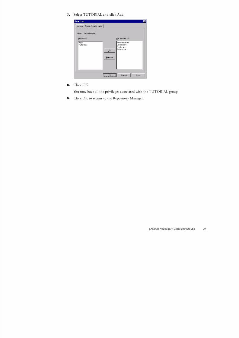
6. Click the Group Memberships tab.
8/6/2019 a Power Center 8.1 Getting Start
http://slidepdf.com/reader/full/a-power-center-81-getting-start 47/158

8/6/2019 a Power Center 8.1 Getting Start
http://slidepdf.com/reader/full/a-power-center-81-getting-start 48/158

8/6/2019 a Power Center 8.1 Getting Start
http://slidepdf.com/reader/full/a-power-center-81-getting-start 49/158
Creating Source Tables
Before you continue with the other lessons in this book, you need to create the source tables

8/6/2019 a Power Center 8.1 Getting Start
http://slidepdf.com/reader/full/a-power-center-81-getting-start 50/158
40 Ch ap ter 3: Tut ori al Le sson 1
y yin the database. In this section, you run an SQL script in the Target Designer to create samplesource tables. The SQL script creates sources with 7-bit ASCII table names and data.
When you run the SQL script, you create the following source tables:
♦ CUSTOMERS♦ DEPARTMENT♦ DISTRIBUTORS♦ EMPLOYEES♦
ITEMS♦ ITEMS_IN_PROMOTIONS♦ JOBS♦ MANUFACTURERS♦ ORDERS♦ ORDER_ITEMS
♦ PROMOTIONS♦ STORES
The Target Designer generates SQL based on the definitions in the workspace. Generally, youuse the Target Designer to create target tables in the target database. In this lesson, you usethis feature to generate the source tutorial tables from the tutorial SQL scripts that ship withthe product. When you run the SQL script, you also create a stored procedure that you willuse to create a Stored Procedure transformation in another lesson.
To create the sample source tables:
1. Launch the Designer, double-click the icon for the repository, and log in to therepository.
Use your user profile to open the connection.
2. Double-click the Tutorial_ yourname folder.
3.Click Tools > Target Designer to open the Target Designer.
4. Click Targets > Generate/Execute SQL.

8/6/2019 a Power Center 8.1 Getting Start
http://slidepdf.com/reader/full/a-power-center-81-getting-start 51/158
Creating Source Tables 41
The Database Object Generation dialog box gives you several options for creating tables.5. Click the Connect button to connect to the source database.
6. Select the ODBC data source you created to connect to the source database. Use theinformation you entered in Table 2-4 on page 29.
7. Enter the database user name and password and click Connect.
You now have an open connection to the source database. When you are connected, the
Disconnect button appears and the ODBC name of the source database appears in thedialog box.
8. Make sure the Output window is open at the bottom of the Designer.
If it is not open, click View > Output.
9. Click the browse button to find the SQL file. The SQL file is installed in the followingdirectory:
C:\Program Files\Informatica PowerCenter\client\bin
10. Select the SQL file appropriate to the source database platform you are using. Click Open.
Alternatively, you can enter the path and file name of the SQL file.
Platform File
Informix smpl_inf.sql
Microsoft SQL Server smpl_ms.sql
Oracle smpl_ora.sql
Sybase ASE smpl_syb.sql
DB2 smpl_db2.sql
Teradata smpl_tera.sql
11. Click Execute SQL file.
The database now executes the SQL script to create the sample source database objectsand to insert values into the source tables. While the script is running, the Outputwindow displays the progress The Designer generates and executes SQL scripts in

8/6/2019 a Power Center 8.1 Getting Start
http://slidepdf.com/reader/full/a-power-center-81-getting-start 52/158
42 Ch ap ter 3: Tut ori al Le sson 1
window displays the progress. The Designer generates and executes SQL scripts inUnicode (UCS2) format.
12. When the script completes, click Disconnect, and then click Close.

8/6/2019 a Power Center 8.1 Getting Start
http://slidepdf.com/reader/full/a-power-center-81-getting-start 53/158

8/6/2019 a Power Center 8.1 Getting Start
http://slidepdf.com/reader/full/a-power-center-81-getting-start 54/158

8/6/2019 a Power Center 8.1 Getting Start
http://slidepdf.com/reader/full/a-power-center-81-getting-start 55/158
Creating Source Definitions
Now that you have added the source tables containing sample data, you are ready to create thesource definitions in the repository. The repository contains a description of source tables,

8/6/2019 a Power Center 8.1 Getting Start
http://slidepdf.com/reader/full/a-power-center-81-getting-start 56/158
46 Ch ap ter 4: Tut ori al Le sson 2
source definitions in the repository. The repository contains a description of source tables,not the actual data contained in them. After you add these source definitions to therepository, you use them in a mapping.
To import the sample source definitions:
1. In the Designer, click Tools > Source Analyzer to open the Source Analyzer.
2. Double-click the tutorial folder to view its contents.
Every folder contains nodes for sources, targets, schemas, mappings, mapplets, cubes,
dimensions and reusable transformations.3. Click Sources > Import from Database.
4. Select the ODBC data source to access the database containing the source tables.
5. Enter the user name and password to connect to this database. Also, enter the name of the source table owner, if necessary.
Use the database connection information you entered inTable 2-4 on page 29.
In Oracle, the owner name is the same as the user name. Make sure that the owner nameis in all caps (for example, JDOE).
6. Click Connect.
7. In the Select tables list, expand the database owner and the TABLES heading.
If you click the All button, you can see all tables in the source database.
You should now see a list of all the tables you created by running the SQL script inaddition to any tables already in the database.

8/6/2019 a Power Center 8.1 Getting Start
http://slidepdf.com/reader/full/a-power-center-81-getting-start 57/158
The Designer displays the newly imported sources in the workspace. You can click Layout > Scale to Fit to fit all the definitions in the workspace.

8/6/2019 a Power Center 8.1 Getting Start
http://slidepdf.com/reader/full/a-power-center-81-getting-start 58/158
48 Ch ap ter 4: Tut ori al Le sson 2
A new database definition (DBD) node appears under the Sources node in the tutorialfolder. This new entry has the same name as the ODBC data source to access the sourcesyou just imported. If you double-click the DBD node, the list of all the imported sourcesappears.
Viewing Source Definitions You can view details for each source definition.
To view a source definition:
1. Double-click the title bar of the source definition for the EMPLOYEES table to open theEMPLOYEES source definition.
The Edit Tables dialog box appears and displays all the properties of this sourcedefinition. The Table tab shows the name of the table, business name, owner name, andthe database type. You can add a comment in the Description section.
2. Click the Columns tab.
The Columns tab displays the column descriptions for the source table.
Note: The source definition must match the structure of the source table. Therefore, youmust not modify source column definitions after you import them.

8/6/2019 a Power Center 8.1 Getting Start
http://slidepdf.com/reader/full/a-power-center-81-getting-start 59/158
Creating Source Definitions 49
3. Click the Metadata Extensions tab.
Metadata extensions allow you to extend the metadata stored in the repository by associating information with individual repository objects. For example, you can storecontact information, such as name or email address, with the sources you create.
In this lesson, you create user-defined metadata extensions that define the date youcreated the source definition and the name of the person who created the sourcedefinition.
4. Click the Add button to add a metadata extension.
5. Name the new row SourceCreationDate and enter today’s date as the value.
6. Click the Add button to add another metadata extension and name it SourceCreator.
7. Enter your first name as the value in the SourceCreator row.
The Metadata Extensions tab should look similar to this:

8/6/2019 a Power Center 8.1 Getting Start
http://slidepdf.com/reader/full/a-power-center-81-getting-start 60/158
Creating Target Definitions and Target Tables
You can import target definitions from existing target tables, or you can create the definitionsand then generate and run the SQL to create the target tables. In this lesson, you create atarget definition in the Target Designer and then create a target table based on the definition

8/6/2019 a Power Center 8.1 Getting Start
http://slidepdf.com/reader/full/a-power-center-81-getting-start 61/158
Creating Target Definitions and Target Tables 51
target definition in the Target Designer, and then create a target table based on the definition.
Creating Target DefinitionsThe next step is to create the metadata for the target tables in the repository. The actual tablesthat the target definitions describe do not exist yet.
Target definitions define the structure of tables in the target database, or the structure of filetargets the Integration Service creates when you run a session. If you add a relational target
definition to the repository that does not exist in a database, you need to create target table. You do this by generating and executing the necessary SQL code within the Target Designer.
In the following steps, you copy the EMPLOYEES source definit ion into the Target Designerto create the target definition. Then, you modify the target definition by deleting and addingcolumns to create the definition you want.
To create the T_EMPLOYEES target definition:
1. In the Designer, click Tools > Target Designer to open the Target Designer.2. Drag the EMPLOYEES source definition from the Navigator to the Target Designer
workspace.
The Designer creates a new target definition, EMPLOYEES, with the same columndefinitions as the EMPLOYEES source definition and the same database type.
Next, modify the target column definitions.
3. Double-click the EMPLOYEES target definition to open it.4. Click Rename and name the target definition T_EMPLOYEES.
Note: If you need to change the database type for the target definition, you can select thecorrect database type when you edit the target definition.
5. Click the Columns tab.

8/6/2019 a Power Center 8.1 Getting Start
http://slidepdf.com/reader/full/a-power-center-81-getting-start 62/158

8/6/2019 a Power Center 8.1 Getting Start
http://slidepdf.com/reader/full/a-power-center-81-getting-start 63/158

8/6/2019 a Power Center 8.1 Getting Start
http://slidepdf.com/reader/full/a-power-center-81-getting-start 64/158
What Comes Next
In the next lesson, you create a mapping to design the data flow between sources and targets. You specify how each column in the target table receives data from a column in the sourcetable.

8/6/2019 a Power Center 8.1 Getting Start
http://slidepdf.com/reader/full/a-power-center-81-getting-start 65/158
What Comes Next 55

8/6/2019 a Power Center 8.1 Getting Start
http://slidepdf.com/reader/full/a-power-center-81-getting-start 66/158
C h a p t e r 5

8/6/2019 a Power Center 8.1 Getting Start
http://slidepdf.com/reader/full/a-power-center-81-getting-start 67/158
57
C h a p t e r 5
Tutorial Lesson 3
This chapter includes the following topics:
♦ Creating a Pass-Through Mapping, 58♦ Creating Sessions and Workflows, 62♦ Running and Monitoring Workflows, 71♦ What Comes Next, 74
Creating a Pass-Through Mapping
In the previous lesson, you added source and target definitions to the repository. You alsogenerated and ran the SQL code to create target tables.
The next step is to create a mapping to depict the flow of data between sources and targets.

8/6/2019 a Power Center 8.1 Getting Start
http://slidepdf.com/reader/full/a-power-center-81-getting-start 68/158
58 Ch ap ter 5: Tut ori al Le sson 3
p pp g p gFor this step, you create a Pass-Through mapping. A Pass-Through mapping inserts all thesource rows into the target.
To create and edit mappings, you use the Mapping Designer tool in the Designer. Themapping interface in the Designer iscomponent-based . You add transformations to a mappingthat depict how the Integration Service extracts and transforms data before it loads a target.
Figure 5-1 shows a mapping between a source and a target with a Source Qualifiertransformation:
The source qualifier represents the rows that the Integration Service reads from the source when it runs a session.If you examine the mapping, you see that data flows from the source definition to the SourceQualifier transformation to the target definition through a series of input and output ports.
The source provides information, so it contains only output ports, one for each column. Eachoutput port is connected to a corresponding input port in the Source Qualifiertransformation. The Source Qualifier transformation contains both input and output ports.The target contains input ports.
When you design mappings that contain different types of transformations, you can configuretransformation ports as inputs, outputs, or both. You can rename ports and change thedatatypes.
Figure 5-1. Pass-Through Mapping
Output Port
Input Port
Input/OutputPort
Creating a MappingIn the following steps, you create a mapping and link columns in the source EMPLOYEEStable to a Source Qualifier transformation.
To create a mapping:

8/6/2019 a Power Center 8.1 Getting Start
http://slidepdf.com/reader/full/a-power-center-81-getting-start 69/158
Creating a Pass-Through Mapping 59
1. Click Tools > Mapping Designer to open the Mapping Designer.2. In the Navigator, expand the Sources node in the tutorial folder, and then expand the
DBD node containing the tutorial sources.
3. Drag the EMPLOYEES source definition into the Mapping Designer workspace.
The Designer creates a new mapping and prompts you to provide a name.
4. In the Mapping Name dialog box, enter m_PhoneList as the name of the new mappingand click OK.
The naming convention for mappings is m_ MappingName .
The source definition appears in the workspace. The Designer creates a Source Qualifiertransformation and connects it to the source definition.
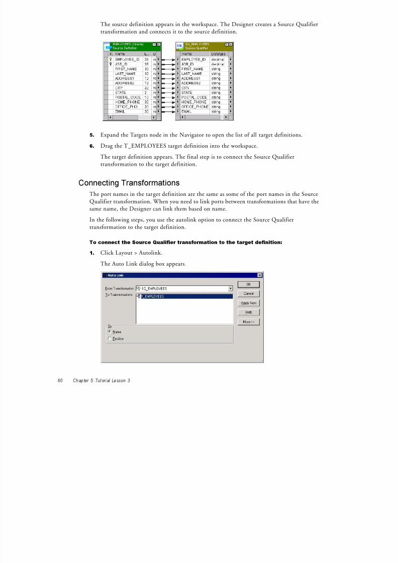
8/6/2019 a Power Center 8.1 Getting Start
http://slidepdf.com/reader/full/a-power-center-81-getting-start 70/158
60 Ch ap ter 5: Tut ori al Le sson 3
5. Expand the Targets node in the Navigator to open the list of all target definitions.
6. Drag the T_EMPLOYEES target definition into the workspace.
The target definition appears. The final step is to connect the Source Qualifiertransformation to the target definition.
Connecting TransformationsThe port names in the target definition are the same as some of the port names in the SourceQualifier transformation. When you need to link ports between transformations that have thesame name, the Designer can link them based on name.
In the following steps, you use the autolink option to connect the Source Qualifiertransformation to the target definition.
To connect the Source Qualifier transformation to the target definition:
1. Click Layout > Autolink.
The Auto Link dialog box appears.
2. Select T_EMPLOYEES in the To Transformations field. Verify that SQ_EMPLOYEES isin the From Transformation field.
3. Autolink by name and click OK.
The Designer links ports from the Source Qualifier transformation to the targetdefinition by name. A link appears between the ports in the Source Qualifier
f i d h d fi i i

8/6/2019 a Power Center 8.1 Getting Start
http://slidepdf.com/reader/full/a-power-center-81-getting-start 71/158
Creating a Pass-Through Mapping 61
transformation and the target definition.
Note: When you need to link ports with different names, you can drag from the port of one transformation to a port of another transformation or target. If you connect the
wrong columns, select the link and press the Delete key.
4. Click Layout > Arrange.
5. In the Select Targets dialog box, select the T_EMPLOYEES target and click OK.
The Designer rearranges the source, Source Qualifier transformation, and target from leftto right, making it easy to see how one column maps to another.
6. Drag the lower edge of the source and Source Qualifier transformation windows until all
columns appear.7. Click Repository > Save to save the new mapping to the repository.
Creating Sessions and Workflows
A session is a set of instructions that tells the Integration Service how to move data fromsources to targets. A session is a task, similar to other tasks available in the Workflow Manager. You create a session for each mapping that you want the Integration Service to run.
Th I t g ti S i th i t ti fig d i th i d i g t

8/6/2019 a Power Center 8.1 Getting Start
http://slidepdf.com/reader/full/a-power-center-81-getting-start 72/158
62 Ch ap ter 5: Tut ori al Le sson 3
The Integration Service uses the instructions configured in the session and mapping to movedata from sources to targets.
A workflow is a set of instructions that tells the Integration Service how to execute tasks, suchas sessions, email notifications, and shell commands. You create a workflow for sessions you
want the Integration Service to run. You can include multiple sessions in a workflow to runsessions in parallel or sequential ly. The Integration Service uses the instructions configured inthe workflow to run sessions and other tasks.
Figure 5-2 shows a workflow with multiple branches and tasks:
You create and maintain tasks and workflows in the Workflow Manager.
In this lesson, you create a session and a workflow that runs the session. Before you create asession in the Workflow Manager, you need to configure database connections in the
Workflow Manager.
Figure 5-2. Sample WorkflowStart Task
Command Task
Session Task
Assignment Task

8/6/2019 a Power Center 8.1 Getting Start
http://slidepdf.com/reader/full/a-power-center-81-getting-start 73/158
6. Select the appropriate database type and click OK.
The Connection Object Definition dialog box appears with options appropriate to theselected database platform.

8/6/2019 a Power Center 8.1 Getting Start
http://slidepdf.com/reader/full/a-power-center-81-getting-start 74/158
64 Ch ap ter 5: Tut ori al Le sson 3
7. In the Name field, enter TUTORIAL_SOURCE as the name of the database connection.
The Integration Service uses this name as a reference to this database connection.
8. Enter the database name. Enter the user name and password to connect to the database.
9. Select a code page for the database connection. The source code page must be a subset of the target code page.
Use the database connection information you entered for the source database inTable 2-5 on page 29.
10. Enter additional information necessary to connect to this database, such as the nativeconnect string, and click OK.
TUTORIAL_SOURCE now appears in the list of registered database connections in theRelational Connection Browser dialog box.
11. Repeat steps 5 to 10 to create another database connection calledTUTORIAL_TARGET for the target database.
The target code page must be a superset of the source code page.
Use the database connection information you entered for the target database inTable 2-5on page 29.

8/6/2019 a Power Center 8.1 Getting Start
http://slidepdf.com/reader/full/a-power-center-81-getting-start 75/158

8/6/2019 a Power Center 8.1 Getting Start
http://slidepdf.com/reader/full/a-power-center-81-getting-start 76/158
10. Select Sources in the Transformations pane on the left.

8/6/2019 a Power Center 8.1 Getting Start
http://slidepdf.com/reader/full/a-power-center-81-getting-start 77/158
Creating Sessions and Workflows 67
11. In the Connections settings to the right, click the Browse Connections button in theValue column for the SQ_EMPLOYEES - DB Connection.
The Relational Connection Browser appears.
12. Select TUTORIAL_SOURCE and click OK.
13. Select Targets in the Transformations pane.
14. In the Connections settings, click the Edit button in the Value column for theT_EMPLOYEES - DB Connection.
The Relational Connection Browser appears.
15. Select TUTORIAL_TARGET and click OK.
16. Click the Properties tab.
17. Select a session sort order associated with the Integration Service code page.
Browse
ConnectionsButton

8/6/2019 a Power Center 8.1 Getting Start
http://slidepdf.com/reader/full/a-power-center-81-getting-start 78/158
The Create Workflow dialog box appears.
BrowseIntegration

8/6/2019 a Power Center 8.1 Getting Start
http://slidepdf.com/reader/full/a-power-center-81-getting-start 79/158
Creating Sessions and Workflows 69
4. Enter wf_PhoneList as the name for the workflow.
The naming convention for workflows is wf_WorkflowName .
5. Click the Browse Integration Services button to choose an Integration Service to run the workflow.
The Integration Service Browser dialog box appears.
6. Select the appropriate Integration Service, and click OK.
7. Click the Properties tab to view the workflow properties.
8. Enter wf_PhoneList.log for the workflow log file name.
IntegrationServices.

8/6/2019 a Power Center 8.1 Getting Start
http://slidepdf.com/reader/full/a-power-center-81-getting-start 80/158
Running and Monitoring Workflows
When the Integration Service runs workflows, you can monitor workflow progress in the Workflow Monitor. You can view details about a workflow or task in either a Gantt Chartview or a Task view. You can start, stop, and abort workflows from the Workflow Monitor.
The Workflow Monitor displays workflows that have run at least once.In the following steps you run a workflow and monitor it

8/6/2019 a Power Center 8.1 Getting Start
http://slidepdf.com/reader/full/a-power-center-81-getting-start 81/158
Running and Monitoring Workflows 71
In the following steps, you run a workflow and monitor it.
Opening the Workflow Monitor You can configure the Workflow Manager to open the Workflow Monitor when you run a workflow from the Workflow Manager.
You can also open the Workflow Monitor from the Workflow Manager Navigator or from the Windows Start menu.
For more information about using the Workflow Monitor, see “Monitoring Workflows” in theWorkflow Administration Guide .
To configure the Workflow Manager to open the Workflow Monitor:
1. In the Workflow Manager, click Tools > Options.
2. In the General tab, select Launch Workflow Monitor When Workflow Is Started.
3. Click OK.
Next, you run the workflow and open the Workflow Monitor.
Running the Workflow After you create a workflow containing a session, you can run it to move the data from thesource to the target.
To run a workflow:
1. Verify the workflow is open in the Workflow Designer.
2. In the Workflow Manager, click Workflows > Start Workflow.Tip: You can also right-click the workflow in the Navigator and select Star t Workflow.

8/6/2019 a Power Center 8.1 Getting Start
http://slidepdf.com/reader/full/a-power-center-81-getting-start 82/158
2109 Centre Tom 415-541-5145
(12 rows affected)
EMPLOYEE_ID LAST_NAME FIRST_NAME OFFICE_PHONE

8/6/2019 a Power Center 8.1 Getting Start
http://slidepdf.com/reader/full/a-power-center-81-getting-start 83/158
Running and Monitoring Workflows 73

8/6/2019 a Power Center 8.1 Getting Start
http://slidepdf.com/reader/full/a-power-center-81-getting-start 84/158
C h a p t e r 6

8/6/2019 a Power Center 8.1 Getting Start
http://slidepdf.com/reader/full/a-power-center-81-getting-start 85/158
75
Tutorial Lesson 4
This chapter includes the following topics:
♦ Using Transformations, 76♦ Creating a New Target Definition and Target, 78♦ Creating a Mapping with Aggregate Values, 82♦ Designer Tips, 92♦ Creating a Session and Workflow, 94♦ What Comes Next, 100
Using Transformations
In this lesson, you create a mapping that contains a source, multiple transformations, and atarget.
A transformation is a part of a mapping that generates or modifies data. Every mapping
includes a Source Qualifier transformation, representing all data read from a source andtemporarily stored by the Integration Service. In addition, you can add transformations that
l l t l k l g t i ID b f th d t h th

8/6/2019 a Power Center 8.1 Getting Start
http://slidepdf.com/reader/full/a-power-center-81-getting-start 86/158
76 Ch ap ter 6: Tut ori al Le sson 4
calculate a sum, look up a value, or generate a unique ID before the source data reaches thetarget.
Figure 6-1 shows the Transformation toolbar:
Table 6-1 lists the transformations displayed in the Transformation toolbar in the Designer:
Figure 6-1. Transformation Toolbar
Table 6-1. Transformation Descriptions
Transformation Description
Aggregator Performs aggregate calculations.
Application Source Qualifier Represents the rows that the Integration Service reads from an application, suchas an ERP source, when it runs a workflow.
Application Multi-Group SourceQualifier
Represents the rows that the Integration Service reads from an application, suchas a TIBCO source, when it runs a workflow. Sources that require an ApplicationMulti-Group Source Qualifier contain multiple groups.
Custom Calls a procedure in a shared library or DLL.
Expression Calculates a value.
External Procedure Calls a procedure in a shared lib rary or in the COM layer of Windows.
Filter Filters data.
Input Defines mapplet input rows. Available in the Mapplet Designer.
Joiner Joins data from different databases or flat file systems.
Lookup Looks up values.
MQ Series Source Qualifier Represents the rows that the Integration Service reads from an MQSeriesmessage queue source when it runs a workflow.
Normalizer Source qualifier for COBOL sources. Can also use in the pipeline to normalizedata from relational or flat file sources.
Output Defines mapplet output rows. Available in the Mapplet Designer.
Rank Limits records to a top or bottom range.
Router Routes data into multiple transformations based on group conditions.

8/6/2019 a Power Center 8.1 Getting Start
http://slidepdf.com/reader/full/a-power-center-81-getting-start 87/158
Creating a New Target Definition and Target
Before you create the mapping in this lesson, you need to design a target that holds summary data about products from various manufacturers. This table includes the maximum andminimum price for products from a given manufacturer, an average price, and an averageprofit.
After you create the target definition, you create the table in the target database.

8/6/2019 a Power Center 8.1 Getting Start
http://slidepdf.com/reader/full/a-power-center-81-getting-start 88/158
78 Ch ap ter 6: Tut ori al Le sson 4
Creating a Target DefinitionTo create the target definition in this lesson, you copy the MANUFACTURERS sourcedefinition into the Target Designer. Then, you modify the target definit ion by addingcolumns to create the definition you want.
Note: You can also manually create a target definition, import the definition for an existingtarget from a database, or create a relational target from a transformation in the Designer. Formore information about creating target definitions, see “Working with Targets” in theDesigner Guide .
To create the new target definition:
1. Open the Designer, connect to the repository, and open the tutorial folder.
2. Click Tools > Target Designer.
3. Drag the MANUFACTURERS source definition from the Navigator to the TargetDesigner workspace.
The Designer creates a target definition, MANUFACTURERS, with the same columndefinitions as the MANUFACTURERS source definition and the same database type.
Next, you add target column definitions.
4. Double-click the MANUFACTURERS target definition to open it.
The Edit Tables dialog box appears.
5. Click Rename and name the target definition T_ITEM_SUMMARY.
6. Optionally, change the database type for the target definition. You can select the correctdatabase type when you edit the target definition.
7. Click the Columns tab.The target column definitions are the same as the MANUFACTURERS sourcedefinition.
8. For the MANUFACTURER_NAME column, change precision to 72, and clear the NotNull column.
Add Button

8/6/2019 a Power Center 8.1 Getting Start
http://slidepdf.com/reader/full/a-power-center-81-getting-start 89/158
Creating a New Target Definition and Target 79
9. Add the following columns with the Money datatype, and select Not Null:♦ MAX_PRICE♦ MIN_PRICE♦ AVG_PRICE♦ AVG_PROFIT
Use the default precision and scale with the Money datatype. If the Money datatype doesnot exist in the database, use Number (p,s) or Decimal. Change the precision to 15 andthe scale to 2.
10. Click Apply.

8/6/2019 a Power Center 8.1 Getting Start
http://slidepdf.com/reader/full/a-power-center-81-getting-start 90/158
80 Ch ap ter 6: Tut ori al Le sson 4
11. Click the Indexes tab to add an index to the target table.
If the target database is Oracle, skip to the final step. You cannot add an index to a
column that already has the PRIMARY KEY constraint added to it.
12. In the Indexes section, click the Add button.
13. Enter IDX_MANUFACTURER_ID as the name of the new index, and then press Enter.
14. Select the Unique index option.
15.In the Columns section, click Add.
Add Button
The Add Column To Index dialog box appears. It lists the columns you added to thetarget definition.
16. Select MANUFACTURER_ID and click OK.
17. Click OK to save the changes to the target definition, and then click Repository > Save.
Creating a Target TableIn the following steps, you use the Designer to generate and execute the SQL script to create a
f
8/6/2019 a Power Center 8.1 Getting Start
http://slidepdf.com/reader/full/a-power-center-81-getting-start 91/158
Creating a New Target Definition and Target 81
target table based on the target definition you created.
To create the table in the database:
1. Select the table T_ITEM_SUMMARY, and then click Targets > Generate/Execute SQL.
2. In the Database Object Generation dialog box, connect to the target database.3. Click Generate from Selected tables, and select the Create Table, Primary Key, and Create
Index options.
Leave the other options unchanged.
4. Click Generate and Execute.
The Designer notifies you that the file MKT_EMP.SQL already exists.
5. Click OK to override the contents of the file and create the target table.
The Designer runs the SQL script to create the T_ITEM_SUMMARY table.
6. Click Close.

8/6/2019 a Power Center 8.1 Getting Start
http://slidepdf.com/reader/full/a-power-center-81-getting-start 92/158
The Mapping Designer adds an Aggregator transformation to the mapping.

8/6/2019 a Power Center 8.1 Getting Start
http://slidepdf.com/reader/full/a-power-center-81-getting-start 93/158
Creating a Mapping with Aggre gate Values 83
3. Click Layout > Link Columns.
When you drag ports from one transformation to another, the Designer copies the portdescription and links the original port to its copy.
If you click Layout > Copy Columns, every port you drag is copied, but not linked.
4. From the Source Qualifier transformation, drag the PRICE column into the Aggregator
transformation. A copy of the PRICE port now appears in the new Aggregator transformation. The new port has the same name and datatype as the port in the Source Qualifier transformation.
The Aggregator transformation receives data from the PRICE port in the SourceQualifier transformation. You need this information to calculate the maximum,minimum, and average product price for each manufacturer.
5. Drag the MANUFACTURER_ID port into the Aggregator transformation. You need another input port, MANUFACTURER_ID, to provide the information forthe equivalent of a GROUP BY statement. By adding this second input port, you candefine the groups (in this case, manufacturers) for the aggregate calculation. Thisorganizes the data by manufacturer.
6. Double-click the Aggregator transformation, and then click the Ports tab.
7. Clear the Output (O) column for PRICE.
You want to use this port as an input (I) only, not as an output (O). Later, you use datafrom PRICE to calculate the average, maximum, and minimum prices.
8. Select the Group By option for the MANUFACTURER_ID column.
9. Click the Add button three times to add three new ports.
Add Button

8/6/2019 a Power Center 8.1 Getting Start
http://slidepdf.com/reader/full/a-power-center-81-getting-start 94/158
84 Ch ap ter 6: Tut ori al Le sson 4
When you select the Group By option for MANUFACTURER_ID, the IntegrationService groups all incoming rows by manufacturer ID when it runs the session.
10. Configure the following ports:
Tip: You can select each port and click the Up and Down buttons to position the outputports after the input ports in the list.
11. Click Apply to save the changes.
Now, you need to enter the expressions for all three output ports, using the functions MAX,MIN, and AVG to perform aggregate calculations.
Name Datatype Precision Scale I O V
OUT_MIN_PRICE Decimal 19 2 No Yes No
OUT_MAX_PRICE Decimal 19 2 No Yes No
OUT_AVG_PRICE Decimal 19 2 No Yes No

8/6/2019 a Power Center 8.1 Getting Start
http://slidepdf.com/reader/full/a-power-center-81-getting-start 95/158
4. Double-click the MAX function on the list.
The MAX function appears in the window where you enter the expression. To performthe calculation, you need to add a reference to an input port that provides data for theexpression.
5. Move the cursor between the parentheses next to MAX.
6. Click the Ports tab.This section of the Expression Editor displays all the ports from all transformationsappearing in the mapping.

8/6/2019 a Power Center 8.1 Getting Start
http://slidepdf.com/reader/full/a-power-center-81-getting-start 96/158
86 Ch ap ter 6: Tut ori al Le sson 4
7. Double-click the PRICE port appearing beneath AGG_PriceCalculations.
A reference to this port now appears within the expression. The final s tep is to validatethe expression.
8. Click Validate.
The Designer displays a message that the expression parsed successfully. The syntax youentered has no errors.
9. Click OK to close the message box from the parser, and then click OK again to close theExpression Editor.
To enter the remaining aggregate calculations:
1. Enter and validate the following expressions for the other two output ports:
Both MIN and AVG appear in the list of Aggregate functions, along with MAX.
Port Expression
OUT_MIN_PRICE MIN(PRICE)
OUT_AVG_PRICE AVG(PRICE)

8/6/2019 a Power Center 8.1 Getting Start
http://slidepdf.com/reader/full/a-power-center-81-getting-start 97/158

8/6/2019 a Power Center 8.1 Getting Start
http://slidepdf.com/reader/full/a-power-center-81-getting-start 98/158
To add the Lookup transformation:
1. Create a Lookup transformation and name it LKP_Manufacturers.
The naming convention for Lookup transformations is LKP_TransformationName .
A dialog box prompts you to identify the source or target database to provide data for thelookup. When you run a session, the Integration Service must access the lookup table.
2. Click Source.

8/6/2019 a Power Center 8.1 Getting Start
http://slidepdf.com/reader/full/a-power-center-81-getting-start 99/158
Creating a Mapping with Aggre gate Values 89
3. Select the MANUFACTURERS table from the list and click OK.
4. Click Done to close the Create Transformation dialog box.
The Designer now adds the transformation.
Use source and target definitions in the repository to identify a lookup source for theLookup transformation. Alternat ively, using the Import button, you can import a lookupsource.
5. Open the Lookup transformation.
6. Add a new input port, IN_MANUFACTURER_ID, using the same datatype asMANUFACTURER_ID.
In a later step, you connect the MANUFACTURER_ID port from the Aggregatortransformation to this input port. IN_MANUFACTURER_ID receivesMANUFACTURER_ID values from the Aggregator transformation. When the Lookuptransformation receives a new value through this input port, it looks up the matchingvalue from MANUFACTURERS.Note: By default, the Lookup transformation queries and stores the contents of the lookuptable before the rest of the transformation runs, so it performs the join through a local
copy of the table that it has cached. For more information about caching the lookuptable, see “Lookup Caches” in theTransformation Guide .
7. Click the Condition tab, and click the Add button.
An entry for the first condition in the lookup appears. Each row represents one conditionin the WHERE clause that the Integration Service generates when querying records.
8. Verify the following settings for the condition:
Note: If the datatypes (including precision and scale) of these two columns do not match,the Designer displays a message and marks the mapping invalid.
9. View the Properties tab.
Do not change settings in this section of the dialog box For more information about the
Lookup Table Column Operator Transformation Port
MANUFACTURER_ID = IN_MANUFACTURER_ID

8/6/2019 a Power Center 8.1 Getting Start
http://slidepdf.com/reader/full/a-power-center-81-getting-start 100/158
90 Ch ap ter 6: Tut ori al Le sson 4
Do not change settings in this section of the dialog box. For more information about theLookup properties, see “Lookup Transformation” in theTransformation Guide .
10. Click OK.
You now have a Lookup transformation that reads values from the MANUFACTURERStable and performs lookups using values passed through the IN_MANUFACTURER_IDinput port. The final step is to connect this Lookup transformation to the rest of themapping.
11. Click Layout > Link Columns.
12. Connect the MANUFACTURER_ID output port from the Aggregator transformation tothe IN_MANUFACTURER_ID input port in the Lookup transformation.
13. Click Repository > Save.
Connecting the Target You have set up all the transformations needed to modify data before writing to the target. Sofar, you have performed the following tasks:
♦ Created a target definition and target table.♦ Created a mapping.♦ Added transformations.
The final step is to connect to the target.
To connect to the target:
1. Drag the following output ports to the corresponding input ports in the target:
Transformation Output Port Targe t Input Port
Lookup MANUFACTURER_ID MANUFACTURER_ID
Lookup MANUFACTURER_NAME MANUFACTURER_NAMEAggregator OUT_MIN_PRICE MIN_PRICE
Aggregator OUT_MAX_PRICE MAX_PRICE
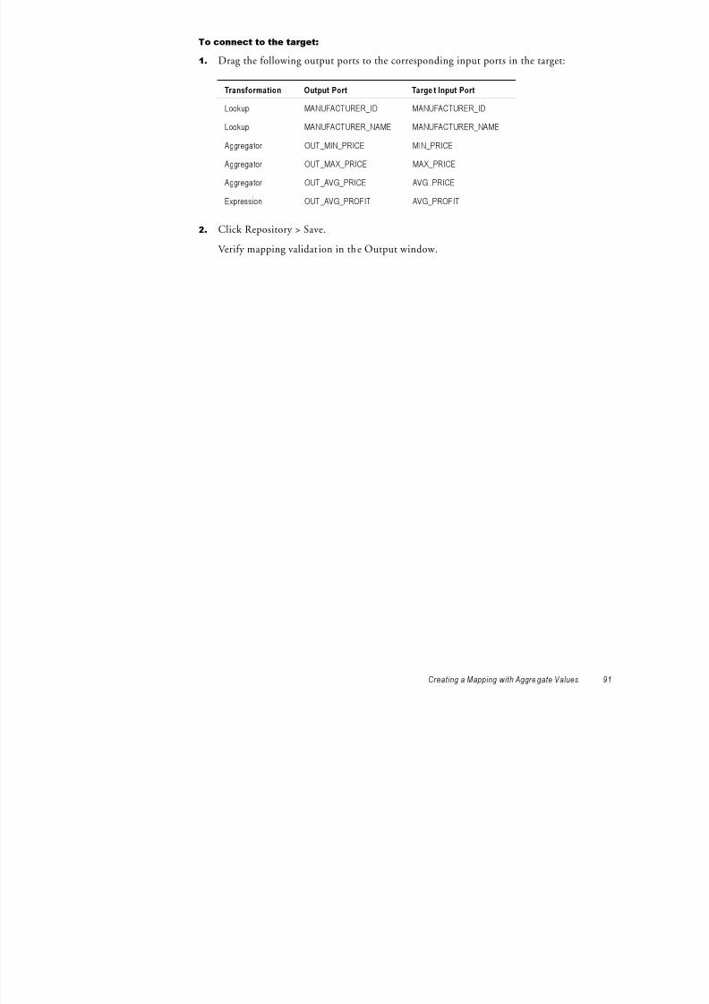
8/6/2019 a Power Center 8.1 Getting Start
http://slidepdf.com/reader/full/a-power-center-81-getting-start 101/158
Creating a Mapping with Aggre gate Values 91
2. Click Repository > Save.Verify mapping validat ion in the Output window.
Aggregator OUT_AVG_PRICE AVG_PRICE
Expression OUT_AVG_PROFIT AVG_PROFIT
Designer Tips
This section includes tips for using the Designer. You learn how to complete the followingtasks:
♦ Use the Overview window to navigate the workspace.
♦ Arrange the transformations in the workspace.
Using the Overview Window

8/6/2019 a Power Center 8.1 Getting Start
http://slidepdf.com/reader/full/a-power-center-81-getting-start 102/158
92 Ch ap ter 6: Tut ori al Le sson 4
When you create a mapping with many transformations, you may not be able to see the ent iremapping in the workspace. In the following steps, you use the Overview window to navigatearound the workspace containing the mapping you just created.
To use the Overview window:
1. Click View > Overview Window.
You can also use the Toggle Overview Window icon.
A window appears, displaying a smaller version of the mapping.
2. Drag the viewing rectangle (the dotted square) within this window.
As you move the viewing rectangle, the perspective on the mapping changes.

8/6/2019 a Power Center 8.1 Getting Start
http://slidepdf.com/reader/full/a-power-center-81-getting-start 103/158
Creating a Session and Workflow
You have two mappings:
♦ m_PhoneList. A pass-through mapping that reads employee names and phone numbers.♦ m_ItemSummary. A more complex mapping that performs simple and aggregate
calculations and lookups. You have a reusable session based on m_PhoneList. Next, you create a session form_ItemSummary in the Workflow Manager. You create a workflow that runs both sessions.

8/6/2019 a Power Center 8.1 Getting Start
http://slidepdf.com/reader/full/a-power-center-81-getting-start 104/158
94 Ch ap ter 6: Tut ori al Le sson 4
Creating the SessionOpen the Workflow Manager and connect to the repository if it is not open already.
To create the session:
1. Open the Task Developer and click Tasks > Create.
2. Create a Session task and name it s_ItemSummary. Click Create.
In the Mappings dialog box, select the mapping m_ItemSummary and click OK.
3. Click Done.
4. Open the session properties for s_ItemSummary.5. Click the Connections setting on the Mapping tab. Select the source database connection
TUTORIAL_SOURCE for SQ_ITEMS.
Use the database connection you created in“Configuring Database Connections in the Workflow Manager” on page 63.
6. Click the Connections setting on the Mapping tab. Select the target database connection
TUTORIAL_TARGET for T_ITEM_SUMMARY.Use the database connection you created in“Configuring Database Connections in the
Workflow Manager” on page 63.
7. Close the session properties and click Repository > Save.
Now that you have two sessions, you can create a workflow and include both sessions in the workflow. When you run the workflow, the Integration Service runs all sessions in the workflow, either simultaneously or in sequence, depending on how you arrange the sessions inthe workflow.
Creating the Workflow You can group sessions in a workflow to improve performance, or to ensure that targets loadin a set order. In the following steps, you create a workflow that runs the sessions s_PhoneListand s_ItemSummary concurrently.
To create a workflow:
1. Click Tools > Workflow Designer.
2. Click Workflows > Create to create a new workflow.
When you have a workflow already open, the Workflow Manager prompts you to close
8/6/2019 a Power Center 8.1 Getting Start
http://slidepdf.com/reader/full/a-power-center-81-getting-start 105/158
Creating a Session and Workflow 95
the current workflow. Click Yes to close any current workflow.
The workflow properties appear.
3.Name the workflow wf_ItemSummary_PhoneList.
4. Click the Browse Integration Service button to select an Integration Service to run the workflow.
The Integration Service Browser dialog box appears.
5. Select an Integration Service and click OK.
6. Click the Properties tab and select Write Backward Compatible Workflow Log File.
The default name of the workflow log file is wf_ItemSummary_PhoneList.log.7. Click the Scheduler tab.
By default, the workflow is scheduled to run on demand. Keep this default.
8. Click OK to close the Create Workflow dialog box.
The Workflow Manager creates a new workflow in the workspace including the Starttask.
9. From the Navigator, drag the s_ItemSummary session to the workspace. Then, drag thes_PhoneList session to the workspace.
10. Click the link tasks button on the toolbar.
11. Drag from the Start task to the s_ItemSummary Session task.
12. Drag from the Start task to the s_PhoneList Session task.
By default, when you link both sessions directly to the Start task, the Integration Service

8/6/2019 a Power Center 8.1 Getting Start
http://slidepdf.com/reader/full/a-power-center-81-getting-start 106/158
96 Ch ap ter 6: Tut ori al Le sson 4
y , y y , gruns both sessions at the same time when you run the workflow. If you want theIntegration Service to run the sessions one after the other, connect the Start task to onesession, and connect that session to the other session.
13. Click Repository > Save to save the workflow in the repository.
You can now run and monitor the workflow.
Running the Workflow After you create the workflow containing the sessions, you can run it and use the Workflow Monitor to monitor the workflow progress.
To run a workflow:
1. Right-click the Start task in the workspace and select Start Workflow from Task.Tip: You can also right-click the workflow in the Navigator and select Star t Workflow.
The Workflow Monitor opens and connects to the repository and opens the tutorialfolder.

8/6/2019 a Power Center 8.1 Getting Start
http://slidepdf.com/reader/full/a-power-center-81-getting-start 107/158
Creating a Session and Workflow 97
Tip: If the Workflow Monitor does not show the current workflow tasks, right-click thetutorial folder and select Get Previous Runs.
2. Click the Gantt Chart tab at the bottom of the Time window to verify the Workflow Monitor is in Gantt Chart view.Note: You can also click the Task View tab at the bottom of the Time window to view the
Workflow Monitor in Task view. You can switch back and forth between views at any time.
3. In the Navigator, expand the node for the workflow.
All tasks in the workflow appear in the Navigator.
The results from running the s_ItemSummary session are as follows:
MANUFACTURER_IDMANUFACTURER_
NAME
MAX_
PRICE
MIN_
PRICE
AVG_
PRICE
AVG_
PROFIT
100 Nike 365.00 169.95 261.24 52.25
101 OBrien 188.00 44.95 134.32 26.86
102 Mistral 390.00 70.00 200.00 40.00
103 Spinnaker 70.00 29.00 52.98 10.60
104 Head 179.00 52.00 98.67 19.73
105 Jesper 325.00 34.95 133.65 26.73
106 Acme 195.00 56.95 143.65 28.73
107 Medallion 235.00 19.95 98.65 19.73
108 Sportstar 280.00 18.00 149.00 29.80
109 WindJammer 430.00 395.00 412.50 82.50
110 Monsoon 280.00 280.00 280.00 56.00
(11 rows affected)
MANUFACTURER_IDMANUFACTURER_NAME
MAX_ PRICE
MIN_
PRICEAVG_
PRICEAVG_
PROFIT

8/6/2019 a Power Center 8.1 Getting Start
http://slidepdf.com/reader/full/a-power-center-81-getting-start 108/158
98 Ch ap ter 6: Tut ori al Le sson 4
Viewing the Logs You can view workflow and session logs using the Log Viewer or using the log files. The LogViewer provides detailed information about each event performed during the workflow run.
To view a log:
1. Right-click the workflow and select Get Workflow Log to view the Log Events window for the workflow.
-or-Right-click a session and select Get Session Log to view the Log Events window for thesession.
Figure 6-2 shows a sample Log Viewer window:
(11 rows affected)
Figure 6-2. Sample Log Viewer
2. Select a row in the log.
The full text of the message appears in the section at the bottom of the window.
3. Sort the log file by column by clicking on the column heading.
4. Optionally, click Find to search for keywords in the log.
5. Optionally, click Save As to save the log as an XML document.
Log Files When you created the workflow, the Workflow Manager assigned default workflow andsession log names and locations on the Properties tab. During the session run, the Integration

8/6/2019 a Power Center 8.1 Getting Start
http://slidepdf.com/reader/full/a-power-center-81-getting-start 109/158
Creating a Session and Workflow 99
Service writes the log files to the locations specified in the session properties.
What Comes Next
In Lesson 5, you create a mapping with Filter, Stored Procedure, and Sequence Generatortransformations that outputs data to a fact table and its dimension tables. Then, you create areusable session with the mapping and run the session in a workflow. You define a link condition so the Integration Service runs the session only if the current date is before a date
you specify.

8/6/2019 a Power Center 8.1 Getting Start
http://slidepdf.com/reader/full/a-power-center-81-getting-start 110/158
100 Chapter 6: Tutorial Lesson 4
C h a p t e r 7

8/6/2019 a Power Center 8.1 Getting Start
http://slidepdf.com/reader/full/a-power-center-81-getting-start 111/158
10 1
Tutorial Lesson 5
This chapter includes the following topics:
♦ Creating a Mapping with Fact and Dimension Tables, 102♦ Creating a Workflow, 113

8/6/2019 a Power Center 8.1 Getting Start
http://slidepdf.com/reader/full/a-power-center-81-getting-start 112/158
To clear the workspace, right-click the workspace and select Clear All.
3. Click Targets > Create.
4. In the Create Target Table dialog box, enter F_PROMO_ITEMS as the name of the new target table, select the database type, and click Create.
5. Repeat step 4 to create the other tables needed for this schema: D_ITEMS,
D_PROMOTIONS, and D_MANUFACTURERS. When you have created all thesetables, click Done.
6. Open each new target, and add the following columns to the appropriate table:
D_ITEMS

8/6/2019 a Power Center 8.1 Getting Start
http://slidepdf.com/reader/full/a-power-center-81-getting-start 113/158
Creating a Mapping with Fact and Dimension Tables 103
D_PROMOTIONS
D_MANUFACTURERS
F_PROMO_ITEMS
Column Datatype Precision Not Null Key
ITEM_ID Integer NA Not Null Primary Key
ITEM_NAME Varchar 72
PRICE Money default
Column Datatype Precision Not Null Key
PROMOTION_ID Integer NA Not Null Primary Key
PROMOTION_NAME Varchar 72
DESCRIPTION Varchar default
START_DATE Datetime default
END_DATE Datetime default
Column Datatype Precision Not Null Key
MANUFACTURER_ID Integer NA Not Null Primary Key
MANUFACTURER_NAME Varchar 72
Column Datatype Precision Not Null Key
PROMO_ITEM_ID Integer NA Not Null Primary Key
FK_ITEM_ID Integer NA Foreign Key
FK_PROMOTION_ID Integer NA Foreign Key
FK_MANUFACTURER_ID Integer NA Foreign Key
The datatypes may vary, depending on the database you choose.Note: For F_PROMO_ITEMS, you include foreign key columns that correspond to theprimary keys in each of the dimension tables.
7. Click Repository > Save.
The next step is to generate and execute the SQL script to create each of these new target
NUMBER_ORDERED Integer NA
DISCOUNT Money default
COMMENTS Varchar default
Column Datatype Precision Not Null Key

8/6/2019 a Power Center 8.1 Getting Start
http://slidepdf.com/reader/full/a-power-center-81-getting-start 114/158
104 Chapter 7: Tutorial Lesson 5
The next step is to generate and execute the SQL script to create each of these new targettables.
To create the tables:
1. Select all the table definitions.
2. Click Targets > Generate/Execute SQL.
3. In the Database Object Generation dialog box, connect to the target database.
4. Select Generate from Selected Tables, and select the options for creating the tables andgenerating keys.
5. Click Generate and Execute.
6. Click Close.
Creating the MappingCreate a mapping to filter out discontinued items, call a stored procedure to find how many of each item customers have ordered, and generate a unique ID for each row in the fact table.
To create the new mapping:
1. In the Designer, switch to the Mapping Designer and create a new mapping.
2. Name the mapping m_PromoItems.
3. From the list of targets, select the tables you just created and drag them into themapping.
4. From the list of sources, add the following sources to the mapping:♦ PROMOTIONS♦ ITEMS_IN_PROMOTIONS♦ ITEMS♦ MANUFACTURERS♦ ORDER_ITEMS
5. Delete all Source Qualifier transformations that the Designer creates when you add thesesource definitions.
6. Add a Source Qualifier transformation named SQ_AllData to the mapping, and connectall the sources to it.

8/6/2019 a Power Center 8.1 Getting Start
http://slidepdf.com/reader/full/a-power-center-81-getting-start 115/158
Creating a Mapping with Fact and Dimension Tables 105
When you create a single Source Qualifier transformation, the Integration Serviceincreases performance with a single read on the source database instead of multiple reads.
7. Click View > Navigator to close the Navigator window to allow extra space in the workspace.
8. Click Repository > Save.
Creating a Filter TransformationThe Filter transformation filters rows from a source. If you connect a Filter transformation toa Source Qualifier transformation, you can filter rows passed through the Source Qualifiertransformation using any condition you want to apply. In this exercise, you removediscontinued items from the mapping.
The mapping contains a Filter transformation that limits rows queried from the ITEMS tableto those items that have not been discontinued.
To create the Filter transformation:
1. Create a Filter transformation and name it FIL_CurrentItems.
2 Drag the following ports from the Source Qualifier transformation into the Filter

8/6/2019 a Power Center 8.1 Getting Start
http://slidepdf.com/reader/full/a-power-center-81-getting-start 116/158
106 Chapter 7: Tutorial Lesson 5
2. Drag the following ports from the Source Qualifier transformation into the Filtertransformation:♦
ITEM_ID♦ ITEM_NAME♦ PRICE♦ DISCONTINUED_FLAG
3. Open the Filter transformation.
4. Click the Properties tab to specify the filter condition.
5. Click the Open button in the Filter Condition field.The Expression Editor dialog box appears.
6. Select the word TRUE in the Formula field and press Delete.
7. Click the Ports tab.
8. Enter DISCONTINUED_FLAG = 0.

8/6/2019 a Power Center 8.1 Getting Start
http://slidepdf.com/reader/full/a-power-center-81-getting-start 117/158
The Sequence Generator transformation has the following properties:
♦ The starting number (normally 1).♦ The current value stored in the repository.♦ The number that the Sequence Generator transformation adds to its current value for
every request for a new ID.♦
The maximum value in the sequence.♦ A flag indicating whether the Sequence Generator transformation counter resets to the
minimum value once it has reached its maximum value.
The Sequence Generator transformation has two output ports, NEXTVAL and CURRVAL, which correspond to the two pseudo-columns in a sequence. When you query a value fromthe NEXTVAL port, the transformation generates a new value.

8/6/2019 a Power Center 8.1 Getting Start
http://slidepdf.com/reader/full/a-power-center-81-getting-start 118/158
108 Chapter 7: Tutorial Lesson 5
p , g
In the new mapping, you add a Sequence Generator transformation to generate IDs for the
fact table F_PROMO_ITEMS. Every time the Integration Service inserts a new row into thetarget table, it generates a unique ID for PROMO_ITEM_ID.
To create the Sequence Generator transformation:
1. Create a Sequence Generator transformation and name it SEQ_PromoItemID.
2. Open the Sequence Generator transformation.
3. Click the Ports tab.
The two output ports, NEXTVAL and CURRVAL, appear in the list.Note: You cannot add any new ports to this transformation or reconfigure NEXTVALand CURRVAL.
4. Click the Properties tab.
The properties for the Sequence Generator transformation appear. You do not have tochange any of these settings.
5. Click OK.
6. Connect the NEXTVAL column from the Sequence Generator transformation to thePROMO_ITEM_ID column in the target table F_PROMO_ITEMS.
7. Click Repository > Save.

8/6/2019 a Power Center 8.1 Getting Start
http://slidepdf.com/reader/full/a-power-center-81-getting-start 119/158
In the mapping, add a Stored Procedure transformation to call this procedure. The StoredProcedure transformation returns the number of orders containing an item to an output port .
To create the Stored Procedure transformation:
1. Create a Stored Procedure transformation and name it SP_GET_ITEM_COUNT.
The Import Stored Procedure dialog box appears.
2. Select the ODBC connection for the source database. Enter a user name, owner name,and password. Click Connect.

8/6/2019 a Power Center 8.1 Getting Start
http://slidepdf.com/reader/full/a-power-center-81-getting-start 120/158
110 Chapter 7: Tutorial Lesson 5
3. Select the stored procedure named SP_GET_ITEM_COUNT from the list and click OK.
4. In the Create Transformation dialog box, click Done.
The Stored Procedure transformation appears in the mapping.5. Open the Stored Procedure transformation, and click the Properties tab.
6. Click the Open button in the Connection Information section.
The Select Database dialog box appears.
7. Select the source database and click OK.
You can call stored procedures in both source and target databases.
Note: You can also select the built-in database connection variable, $Source. When youuse $Source or $Target, the Integration Service determines which source databaseconnection to use when it runs the session. If it cannot determine which connection touse, it fails the session. For more information about using $Source and $Target in aStored Procedure transformation, see “Stored Procedure Transformation” in theTransformation Guide .
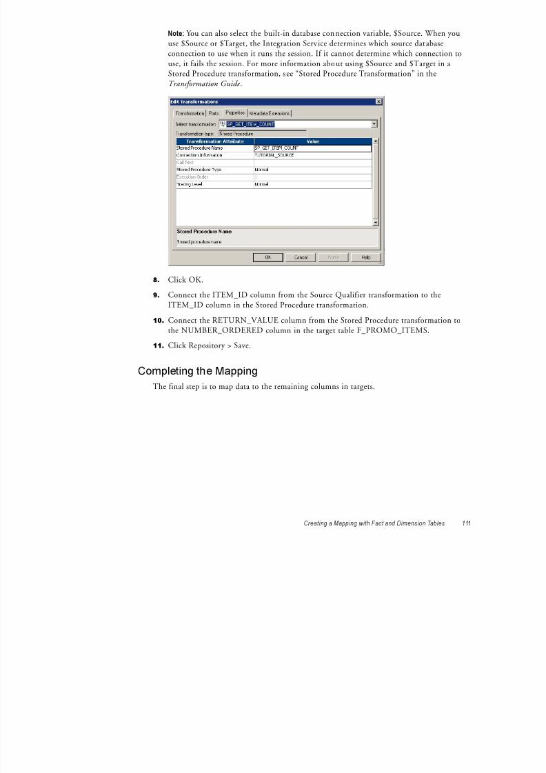
8/6/2019 a Power Center 8.1 Getting Start
http://slidepdf.com/reader/full/a-power-center-81-getting-start 121/158
Creating a Mapping with Fact and Dimension Tables 111
8. Click OK.
9. Connect the ITEM_ID column from the Source Qualifier transformation to theITEM_ID column in the Stored Procedure transformation.
10. Connect the RETURN_VALUE column from the Stored Procedure transformation tothe NUMBER_ORDERED column in the target table F_PROMO_ITEMS.
11. Click Repository > Save.
Completing the MappingThe final step is to map data to the remaining columns in targets.
To complete the mapping:
1. Connect the following columns from the Source Qualifier transformation to the targets:
Source Qualifier Target Table Column
PROMOTION_ID D_PROMOTIONS PROMOTION_ID
PROMOTION_NAME D_PROMOTIONS PROMOTION_NAME
DESCRIPTION D_PROMOTIONS DESCRIPTION
START_DATE D_PROMOTIONS START_DATE
END_DATE D_PROMOTIONS END_DATE
MANUFACTURER_ID D_MANUFACTURERS MANUFACTURER_ID

8/6/2019 a Power Center 8.1 Getting Start
http://slidepdf.com/reader/full/a-power-center-81-getting-start 122/158
112 Chapter 7: Tutorial Lesson 5
2. Click Repository > Save.
The mapping is now complete. You can create and run a new workflow with this mapping.
MANUFACTURER_NAME D_MANUFACTURERS MANUFACTURER_NAME
Creating a Workflow
In this part of the lesson, you complete the following steps:
1. Create a workflow.
2. Add a non-reusable session to the workflow.
3. Define a link condition before the Session task.
Creating the Workflow Open the Workflow Manager and connect to the repository.

8/6/2019 a Power Center 8.1 Getting Start
http://slidepdf.com/reader/full/a-power-center-81-getting-start 123/158
Creating a Workflow 113
To create a workflow:
1. Click Tools > Workflow Designer.2. Click Workflows > Create to create a new workflow.
The workflow properties appear.
3. Name the workflow wf_PromoItems.
4. Click the Browse Integration Service button to select the Integration Service to run the workflow.
The Integration Service Browser dialog box appears.
5. Select the Integration Service you use and click OK.
6. Click the Scheduler tab.
By default, the workflow is scheduled to run on demand. Keep this default.
7. Click OK to close the Create Workflow dialog box.
The Workflow Manager creates a new workflow in the workspace including the Starttask.
Next, you add a non-reusable session in the workflow.
Adding a Non-Reusable SessionIn the following steps, you add a non-reusable session.
To add a non-reusable session:
1. Click Tasks > Create.
The Create Task dialog box appears. The Workflow Designer provides more task typesthan the Task Developer. These tasks include the Email and Decision tasks.
2. Create a Session task and name it s_PromoItems. Click Create.
In the Mappings dialog box, select the mapping m_PromoItems and click OK.
3. Click Done.
4. Open the session properties for s_PromoItems.
5. Click the Mapping tab.
6. Select the source database connection for the sources connected to the SQ_AllDataSource Qualifier transformation.
7. Select the target database for each target definition.8. Click OK to save the changes.
9. Click the Link Tasks button on the toolbar.
10. Drag from the Start task to s_PromoItems.
11. Click Repository > Save to save the workflow in the repository.

8/6/2019 a Power Center 8.1 Getting Start
http://slidepdf.com/reader/full/a-power-center-81-getting-start 124/158
114 Chapter 7: Tutorial Lesson 5
p y p y
You can now define a link condition in the workflow.
Defining a Link Condition After you create links between tasks, you can specify conditions for each link to determine theorder of execution in the workflow. If you do not specify conditions for each link, theIntegration Service executes the next task in the workflow by default.
If the link condition evaluates to True, the Integration Service runs the next task in the workflow. The Integration Service does not run the next task in the workflow if the link condition evaluates to False. You can also use pre-defined or user-defined workflow variablesin the link condition.
You can add comments using -- or // comment indicators with the Expression Editor. Usecomments to describe the expression.
You can view results of link evaluation during workflow runs in the workflow log.
For more information about working with links or workflow variables, see “Working with Workflows” in theWorkflow Administration Guide .
In the following steps, you create a link condition before the Session task and use the built-in workflow variable WORKFLOWSTARTTIME. You define the link condition so theIntegration Service runs the session if the workflow start time is before the date you specify.
To define a link condition:
1. Double-click the link from the Start task to the Session task.
The Expression Editor appears.

8/6/2019 a Power Center 8.1 Getting Start
http://slidepdf.com/reader/full/a-power-center-81-getting-start 125/158
Creating a Workflow 115
2. Expand the Built-in node on the PreDefined tab.
The Workflow Manager displays the two built-in workflow variables, SYSDATE and
WORKFLOWSTARTTIME.3. Enter the following expression in the expression window. Be sure to enter a date later
than today’s date:WORKFLOWSTARTTIME < TO_DATE('8/30/2007', 'MM/DD/YYYY')
Tip: You can double-click the built-in workflow variable on the PreDefined tab anddouble-click the TO_DATE function on the Functions tab to enter the expression. Formore information about using functions in the Expression Editor, see “TheTransformation Language” in theTransformation Language Reference .
4. Press Enter to create a new line in the Expression. Add a comment by typing thefollowing text:
// Only run the session if the workflow starts before the date specifiedabove.

8/6/2019 a Power Center 8.1 Getting Start
http://slidepdf.com/reader/full/a-power-center-81-getting-start 126/158
116 Chapter 7: Tutorial Lesson 5
5. Validate the expression using the Validate button.
The Workflow Manager displays a message in the Output window.
6. Click OK.
After you specify the link condition in the Expression Editor, the Workflow Managervalidates the link condition and displays it next to the link in the workflow.
7. Click Repository > Save to save the workflow in the repository.
Next, you run and monitor the workflow.

8/6/2019 a Power Center 8.1 Getting Start
http://slidepdf.com/reader/full/a-power-center-81-getting-start 127/158
What Comes Next
In Lesson 6, you create a source by importing an XML schema file. You use the XML Editorto edit the XML definition. You also import an XML definition and create a custom view
XML target definition. Then, you create a mapping with Expression and Routertransformations and create a workflow with a non-reusable session to run the mapping.

8/6/2019 a Power Center 8.1 Getting Start
http://slidepdf.com/reader/full/a-power-center-81-getting-start 128/158
118 Chapter 7: Tutorial Lesson 5
C h a p t e r 8

8/6/2019 a Power Center 8.1 Getting Start
http://slidepdf.com/reader/full/a-power-center-81-getting-start 129/158
119
Tutorial Lesson 6
This chapter includes the following topics:
♦ Using XML Files, 120♦ Creating the XML Source, 121♦
Creating the Target, 128♦ Creating a Mapping with XML Sources and Targets, 131♦ Creating a Workflow, 138
Using XML Files
XML is a common means of exchanging data on the web. Use XML files as a source of dataand as a target for transformed data.
In this lesson, you have an XML schema file that contains data on the salary of employees indifferent departments, and you have relational data that contains information about thedifferent departments. You want to find out the total salary for employees in twodepartments, and you want to write the data to a separate XML target for each department.
In the XML schema file, employees can have three types of wages which appear in the XMLschema file as three occurrences of salary. You pivot the occurrences of employee salaries intothree columns: BASESALARY, COMMISSION, and BONUS. Then you calculate the totalsalary in an Expression transformation.
Y R t t f t i t t t f th d t t ID Y th R t

8/6/2019 a Power Center 8.1 Getting Start
http://slidepdf.com/reader/full/a-power-center-81-getting-start 130/158
120 Chapter 8: Tutorial Lesson 6
You use a Router transformation to test for the department ID. You use another Routertransformation to get the department name from the relational source. You send the salary data for the employees in the Engineering department to one XML target and the salary datafor the employees in the Sales department to another XML target.
Figure 8-1 shows the mapping you create in this lesson:
Figure 8-1. Mapping with XML Sources and Targets
Creating the XML Source
You use the XML Wizard to import an XML source definition, and then you use the XMLEditor to edit the definition.
Importing the XML SourceUse the Employees.xsd file to create the XML source definition.
To import the XML source definition:
1. Open the Designer if it is not already open, connect to the repository, and open thetutorial folder.
2. Open the Source Analyzer.

8/6/2019 a Power Center 8.1 Getting Start
http://slidepdf.com/reader/full/a-power-center-81-getting-start 131/158
Creating the XML Source 121
p y
3. Click Sources > Import XML Definition.
4. Click Advanced Options.
The Change XML Views Creation and Naming Options dialog box opens.
5. Select Override All Infinite Lengths and enter 50.
6. Configure all other options as shown and click OK to save the changes.
Override infinite lengths.
7. In the Import XML Definition dialog box, navigate to the client\bin directory under thePowerCenter installation directory and select the Employees.xsd file. Click Open.
The XML Definition Wizard opens.

8/6/2019 a Power Center 8.1 Getting Start
http://slidepdf.com/reader/full/a-power-center-81-getting-start 132/158
122 Chapter 8: Tutorial Lesson 6
8. Verify that the name for the XML defini tion is Employees, and click Next.
9. Select Skip Create XML Views.
Because you only need to work with a few elements and attributes in the Employees.xsdfile, you skip creating a definition using the XML Wizard. Instead, you create a customview in the XML Editor. With a custom view in the XML Editor, you can exclude theelements and attributes that you do not need in the mapping.
10. Click Finish to create the XML definition.
The XML Wizard creates an XML definition with no columns or groups.
When you skip creating XML views, the Designer imports metadata into the repository, but itdoes not create the XML view. In the next step, you use the XML Editor to add groups and

8/6/2019 a Power Center 8.1 Getting Start
http://slidepdf.com/reader/full/a-power-center-81-getting-start 133/158
Creating the XML Source 123
columns to the XML view.
Editing the XML DefinitionThe Designer represents an XML hierarchy in an XML definition as a set of views. Each view represents a subset of the XML hierarchy. A view consists of columns and rows. Columnsrepresent elements and attributes, and rows represent occurrences of elements. You use the
XML Editor to edit the XML views.
In this lesson, you use the XML Editor to pivot the three occurrences of SALARY into threecolumns in an XML group. You do this because the multiple-occurring element SALARY represents three types of salary: a base salary, a commission, and a bonus that appear in the
XML file as three instances of the SALARY element.
Base Salary
Commission
Bonus

8/6/2019 a Power Center 8.1 Getting Start
http://slidepdf.com/reader/full/a-power-center-81-getting-start 134/158
124 Chapter 8: Tutorial Lesson 6
To work with these three instances separately, you pivot them to create three separate columnsin the XML definition.
You create a custom XML view with columns from several groups. You then pivot theoccurrence of SALARY to create the columns, BASESALARY, COMMISSION, and
BONUS.
Figure 8-2 shows the XML Editor:
Figure 8-2. XML Editor

8/6/2019 a Power Center 8.1 Getting Start
http://slidepdf.com/reader/full/a-power-center-81-getting-start 135/158
Creating the XML Source 125
To edit the XML definition:
1. Double-click the XML definition or right-click the XML definition and select Edit XMLDefinition to open the XML Editor.
2. Click XMLViews > Create XML View to create a new XML view.
3. From the EMPLOYEE group, select DEPTID and right-click it.
4. Choose Show XPath Navigator.
5. Expand the EMPLOYMENT group so that the SALARY column appears.
6. From the XPath Navigator, select the following elements and at tributes and drag theminto the new view:♦ DEPTID♦ EMPID
XML WorkspaceXPath NavigatorNavigator XML View
♦ LASTNAME♦ FIRSTNAME
The XML Editor names the view X_EMPLOYEE.Note: The XML Wizard may transpose the order of the DEPTID and EMPID attributes

8/6/2019 a Power Center 8.1 Getting Start
http://slidepdf.com/reader/full/a-power-center-81-getting-start 136/158
126 Chapter 8: Tutorial Lesson 6
when it imports them. If this occurs, you can add the columns in the order they appear inthe Schema Navigator or XPath Navigator. Transposing the order of attributes does notaffect data consistency.
7. Click the Mode icon on the XPath Navigator, and choose Advanced Mode.
8. Select the SALARY column, and drag it into the XML view.Note: The XPath Navigator must include the EMPLOYEE column at the top when youdrag SALARY to the XML view.
The resulting view includes the elements and attributes shown in the following view.
9. Drag the SALARY column into the new XML view two more times to create three
pivoted columns.
Note: Although the new columns appear in the column window, the view shows oneinstance of SALARY.
The wizard adds three new columns in the column view and names them SALARY,SALARY0, and SALARY1.
10. Rename the new columns.

8/6/2019 a Power Center 8.1 Getting Start
http://slidepdf.com/reader/full/a-power-center-81-getting-start 137/158
Creating the XML Source 127
Use information on the following table to modify the name and pivot properties:
Note: To update the pivot occurrence, click the Xpath of the column you want to edit.The Specify Query Predicate for Xpath window appears. Select the column name andchange the pivot occurrence.
11. Click File > Apply Changes to save the changes to the view.
12. Click File > Exit to close the XML Editor.
The following source definition appears in the Source Analyzer.
Note: The pivoted SALARY columns do not display the names you entered in theColumns window. However, when you drag the ports to another transformation, theedited column names appear in the transformation.
13. Click Repository > Save to save the changes to the XML definition.
Column Name New Column Name Not Nul l Pivot Occur rence
SALARY BASESALARY Yes 1
SALARY0 COMMISSION 2
SALARY1 BONUS 3
Creating the Target
In this lesson, you import an XML schema and create a custom view based on the schema.The custom XML target definition you create meets the following criteria:
♦ Each department has a separate target, and the structure for each target is the same.♦ Each target contains salary and department information for employees in the Sales or
Engineering department.Because the structure for the target data is the same for the Engineering and Sales groups, usetwo instances of the target in the mapping. In the following steps, you import theSales_Salary schema file and create a custom view based on the schema.
To import and edit the XML target:
1. In the Designer, switch to the Target Designer.

8/6/2019 a Power Center 8.1 Getting Start
http://slidepdf.com/reader/full/a-power-center-81-getting-start 138/158
128 Chapter 8: Tutorial Lesson 6
If the workspace contains targets from other lessons, right-click the workspace andchoose Clear All.
2. Click Targets > Import XML Definition.
3. Navigate to the Tutorial directory in the PowerCenter installation directory, and selectthe Sales_Salary.xsd file. Click Open.
The XML Definition Wizard appears.
4. Name the XML definition SALES_SALARY and click Next.
5. Select Skip Create XML Views, and click Finish.
The XML Wizard creates the SALES_SALARY target with no columns or groups.
6. Double-click the XML definition to open the XML Editor.
7. Click XMLViews > Create XML View.
The XML Editor creates an empty view.

8/6/2019 a Power Center 8.1 Getting Start
http://slidepdf.com/reader/full/a-power-center-81-getting-start 139/158
Creating the Target 129
8. Right-click DEPARTMENT group in the Schema Navigator and select Show XPathNavigator.
9. From the XPath Navigator, drag DEPTNAME and DEPTID into the empty XML view.
The XML Editor names the view X_DEPARTMENT.Note: The XML Editor may transpose the order of the attributes DEPTNAME andDEPTID. If this occurs, add the columns in the order they appear in the SchemaNavigator. Transposing the order of attributes does not affect data consistency.
10. In the X_DEPARTMENT view, right-click the DEPTID column, and choose Set asPrimary Key.
11. Click XMLViews > Create XML View.
The XML Editor creates an empty view.
12. From the EMPLOYEE group in the Schema Navigator, open the XPath Navigator.
13. From the XPath Navigator, drag EMPID, FIRSTNAME, LASTNAME, andTOTALSALARY into the empty XML view.
The XML Editor names the view X_EMPLOYEE.
14. Right-click the X_EMPLOYEE view, and choose Create Relationship. Drag the pointerfrom the X_EMPLOYEE view to the X_DEPARTMENT view to create a link.
Empty XML View
15. The XML Editor creates a DEPARTMENT foreign key in the X_EMPLOYEE view thatcorresponds to the DEPTID primary key.

8/6/2019 a Power Center 8.1 Getting Start
http://slidepdf.com/reader/full/a-power-center-81-getting-start 140/158
130 Chapter 8: Tutorial Lesson 6
16. Click File > Apply Changes and close the XML Editor.
The XML definition now contains the groups DEPARTMENT and EMPLOYEE.
17. Click Repository > Save to save the XML target definition.
Creating a Mapping with XML Sources and Targets
In the following steps, you create a mapping to transform the employee data. You add thefollowing objects to the mapping:
♦ The Employees XML source definition you created♦ The DEPARTMENT relational source definition you created in“Creating Source
Definitions” on page 46♦ Two instances of the SALES_SALARY target definition you created♦ An Expression transformation to calculate the total salary for each employee♦ Two Router transformations to route salary and department
You pass the data from the Employees source through the Expression and Routertransformations before sending i t to two target instances. You also pass data from the
relational table through another Router transformation to add the department names to the

8/6/2019 a Power Center 8.1 Getting Start
http://slidepdf.com/reader/full/a-power-center-81-getting-start 141/158
Creating a Mapping with XML Sources and Targets 131
relational table through another Router transformation to add the department names to thetargets. You need data for the sales and engineering departments.
To create the mapping:
1. In the Designer, switch to the Mapping Designer and create a new mapping.
2. Name the mapping m_EmployeeSalary.
3. Drag the Employees XML source definition into the mapping.
4. Drag the DEPARTMENT relational source definition into the mapping.
By default, the Designer creates a source qualifier for each source.
5. Drag the SALES_SALARY target into the mapping two times.
6. Rename the second instance of SALES_SALARY as ENG_SALARY.
7. Click Repository > Save.
Because you have not completed the mapping, the Designer displays a warning that themapping m_EmployeeSalary is invalid.
Next, you add an Expression transformation and two Router transformations. Then, youconnect the source definitions to the Expression transformation. You connect the pipeline tothe Router transformations and then to the two target instances.
Creating an Expression TransformationIn the following steps, you use an Expression transformation to calculate the total salary foreach employee. You use BASESALARY, COMMISSION, and BONUS as input columns tothe Expression transformation and create a TotalSalary column as output.
To calculate the total salary:
1. Create an Expression transformation and name it EXP_TotalSalary.
The new transformation appears.
2. Click Done.
3. Drag all the ports from the XML Source Qualifier transformation to theEXP_TotalSalary Expression transformation.
The input/output ports in the XML Source Qualifier transformation are linked to theinput/output ports in the Expression transformation.
4. Open the Expression transformation.
5. On the Ports tab, add an output port named TotalSalary. Use decimal datatype withprecision of 10 and scale of 2.
6.Enter the following expression for TotalSalary:

8/6/2019 a Power Center 8.1 Getting Start
http://slidepdf.com/reader/full/a-power-center-81-getting-start 142/158
132 Chapter 8: Tutorial Lesson 6
Enter the following expression for TotalSalary:BASESALARY + COMMISSION + BONUS
7. Validate the expression and click OK.
8. Click OK to close the transformation.
9. Click Repository > Save.
Creating Router Transformations A Router transformation tests data for one or more conditions and gives you the option toroute rows of data that do not meet any of the conditions to a default output group.
In the following steps, you add two Router transformations to the mapping, one for eachdepartment. In each Router transformation you create two groups. One group returns Truefor rows where the DeptID column contains ‘SLS’. The other group returns True where theDeptID column contains ‘ENG’. All rows that do not meet either condition go into the
default group.
To route the employee salary data:
1. Create a Router transformation and name it RTR_Salary. Then click Done.
2. In the Expression transformation, select the following columns and drag them toRTR_Salary:♦ EmpID♦ DeptID♦ LastName♦ FirstName♦ TotalSalary
The Designer creates an input group and adds the columns you drag from the Expressiontransformation.
3. Open the RTR_Salary Router transformation.
The Edit Transformations dialog box appears.

8/6/2019 a Power Center 8.1 Getting Start
http://slidepdf.com/reader/full/a-power-center-81-getting-start 143/158
Creating a Mapping with XML Sources and Targets 133
4. On the Groups tab, add two new groups. Change the group names and set the filterconditions. Use the following table as a guide:
The Designer adds a default group to the list of groups. All rows that do not meet thecondition you specify in the group filter condition are routed to the default group. If you
do not connect the default group, the Integration Service drops the rows.5. Click OK to close the transformation.
Group Name Fil ter Condition
Sales DEPTID = ‘SLS’
Engineering DEPTID = ‘ENG’
6. In the workspace, expand the RTR_Salary Router transformation to see all groups andports.

8/6/2019 a Power Center 8.1 Getting Start
http://slidepdf.com/reader/full/a-power-center-81-getting-start 144/158
134 Chapter 8: Tutorial Lesson 6
7. Click Repository > Save.
Next, you create another Router transformation to filter the Sales and Engineeringdepartment data from the DEPARTMENT relational source.
To route the department data:
1. Create a Router transformation and name it RTR_DeptName. Then click Done.
2. Drag the DeptID and DeptName ports from the DEPARTMENT Source Qualifier
transformation to the RTR_DeptName Router transformation.3. Open RTR_DeptName.
4. On the Groups tab, add two new groups. Change the group names and set the filterconditions using the following table as a guide:
Group Name Fi lter Condi tion
Sales DEPTID = ‘SLS’
Engineering DEPTID = ‘ENG’
5. On the Ports tab, change the precision for DEPTNAME to 15.
Set precision for the port.

8/6/2019 a Power Center 8.1 Getting Start
http://slidepdf.com/reader/full/a-power-center-81-getting-start 145/158
Creating a Mapping with XML Sources and Targets 135
6. Click OK to close the transformation.
7. In the workspace, expand the RTR_DeptName Router transformation to see all groupsand columns.
8. Click Repository > Save.

8/6/2019 a Power Center 8.1 Getting Start
http://slidepdf.com/reader/full/a-power-center-81-getting-start 146/158

8/6/2019 a Power Center 8.1 Getting Start
http://slidepdf.com/reader/full/a-power-center-81-getting-start 147/158
Creating a Workflow
In the following steps, you create a workflow with a non-reusable session to run the mappingyou just created.
Note: Before you run the workflow based on the XML mapping, you must verify that theIntegration Service that runs the workflow can access the source XML file. Copy the
Employees.xml file from the Tutorial folder to the $PMSourceFileDir directory for theIntegration Service. Usually, this is the SrcFiles directory in the Integration Serviceinstallation directory.
To create the workflow:
1. Open the Workflow Manager if it is not open already. Connect to the repository andopen the tutorial folder.
2. Go to the Workflow Designer.3 Cli k W kfl > Wi d

8/6/2019 a Power Center 8.1 Getting Start
http://slidepdf.com/reader/full/a-power-center-81-getting-start 148/158
138 Chapter 8: Tutorial Lesson 6
3. Click Workflows > Wizard.
The Workflow Wizard opens.
4. Name the workflow wf_EmployeeSalary and select a service on which to run the workflow. Then click Next.
5. Select the m_EmployeeSalary mapping to create a session.

8/6/2019 a Power Center 8.1 Getting Start
http://slidepdf.com/reader/full/a-power-center-81-getting-start 149/158
Creating a Workflow 139
Note: The Workflow Wizard creates a session called s_m_EmployeeSalary.
6. Click Next.
7. Click Run on demand and click Next.The Workflow Wizard displays the settings you chose.
8. Click Finish to create the workflow.
The Workflow Wizard creates a Start task and session. You can add other tasks to the workflow later.
9. Click Repository > Save to save the new workflow.
10. Double-click the s_m_EmployeeSalary session to open it for editing.
11. Click the Mapping tab.
12. Select the connection for the SQ_DEPARTMENT Source Qualifier transformation.

8/6/2019 a Power Center 8.1 Getting Start
http://slidepdf.com/reader/full/a-power-center-81-getting-start 150/158
140 Chapter 8: Tutorial Lesson 6
13. Select the XMLDSQ_Employees source on the Mapping tab.

8/6/2019 a Power Center 8.1 Getting Start
http://slidepdf.com/reader/full/a-power-center-81-getting-start 151/158

8/6/2019 a Power Center 8.1 Getting Start
http://slidepdf.com/reader/full/a-power-center-81-getting-start 152/158
142 Chapter 8: Tutorial Lesson 6
16. Click the SALES_SALARY target instance on the Mapping tab and verify that the outputfile name is sales_salary.xml.
17. Click OK to close the session.
18. Click Repository > Save.
19. Run and monitor the workflow.
The Integration Service creates the eng_salary.xml and sales_salary.xml files.
Edit the output file name.
Figure 8-3 shows the ENG_SALARY.XML file that the Integration Service creates when itruns the session:
Figure 8-3. ENG_SALARY.XML Output

8/6/2019 a Power Center 8.1 Getting Start
http://slidepdf.com/reader/full/a-power-center-81-getting-start 153/158
Creating a Workflow 143

8/6/2019 a Power Center 8.1 Getting Start
http://slidepdf.com/reader/full/a-power-center-81-getting-start 154/158
A p p e n d i x A

8/6/2019 a Power Center 8.1 Getting Start
http://slidepdf.com/reader/full/a-power-center-81-getting-start 155/158
14 5
Naming Conventions
This appendix provides suggested naming conventions for PowerCenter repository objects.

8/6/2019 a Power Center 8.1 Getting Start
http://slidepdf.com/reader/full/a-power-center-81-getting-start 156/158
TargetsThe naming convention for targets is: T_TargetName .
MappingsThe naming convention for mappings is: m_ MappingName .
MappletsThe naming convention for mapplets is: mplt_ MappletName .
XML Parser XP_TransformationName
XML Source Qualifier XSQ_TransformationName
Table A-1. Naming Conventions for Transformations
Transformation Naming Convention

8/6/2019 a Power Center 8.1 Getting Start
http://slidepdf.com/reader/full/a-power-center-81-getting-start 157/158
Suggested Naming Conventions 147
SessionsThe naming convention for sessions is: s_ MappingName .
WorkletsThe naming convention for worklets is: wl_WorkletName .
WorkflowsThe naming convention for workflows is: wf_WorkflowName .

8/6/2019 a Power Center 8.1 Getting Start
http://slidepdf.com/reader/full/a-power-center-81-getting-start 158/158