a primer of oilwell drilling - homepagecee.utexas.edu/ce/petex/files/forms/powd_ebook_demo.pdf · a...
TRANSCRIPT

A Primer ofOilwell Drilling
A Basic Text of Oil and Gas Drilling
Seventh Edition
by Dr. Paul Bommer
2008
published by
The UniversiTy of Texas
ConTinUing edUCaTionPETROLEUM EXTENSION SERVICE
in cooperation with
INTERNaTIONaL aSSOCIaTION Of dRILLINg CONTRaCTORS (IadC)

© 2008 by The University of Texas at AustinAll rights reservedFirst edition published 1951. Sixth edition 2001Seventh edition 2008Printed in the United States of America
This book or parts thereof may not be reproduced in any form without permission from Petroleum Extension Service, The University of Texas at Austin.
Brand names, company names, trademarks, or other identifying symbols appearing in illustrations or text are used for educa-tional purposes only and do not constitute an endorsement by the author or publisher.
Catalog No. 2.00070iSBN 0-88698-227-8
The University of Texas at Austin is an equal opportunity institu-tion. No state tax funds were used to print this book.
Library of Congress Cataloging-in-Publication Data
Bommer, Paul– A primer of oilwell drilling. — 7th ed./ by Paul Bommer p. cm. iSBN 0-88698-227-8 (alk. paper) 1. Oil well drilling. i. University of Texas at Austin. Petroleum Extension Service. ii. Title. TN871.2B316 2001 622'.3382—dc21 00-011902 CiP
iii
figures vi
Tables xiv
Preface xv
about the author xvii
1 Introduction 1
2 History 7The Drake Well, 1850s 9California, Late 1800s 10The Lucas Well, 1901 11The Middle East, 1900s 13
3 Cable-Tool and Rotary drilling 15Cable-Tool Drilling 15Rotary Drilling 16
Rotating Systems 18Fluid Circulation 19
4 Rotary Rig Types 21Land Rigs 22Mobile Offshore Rigs 23
Bottom-Supported MODUs 24Floating Units 30
5 People and Companies 37Operating Companies 38Drilling Contractors 39Drilling Contracts 39Service and Supply Companies 40People 44
Drilling Crews 44Drilling Crew Work Shifts 50Crew Safety 50Other Rig Workers 51
6 Oil and gas: Characteristics and Occurrence 55Natural Gas 55
Liquefied Natural Gas (LNG) 56Liquefied Petroleum Gas (LPG) 56Natural Gas Liquid (NGL) 57
Crude Oil 57Refined Hydrocarbons 57Oil and Gas Reservoirs 58
Characteristics of Reservoir Rocks 58Origin and Accumulation of Oil and Gas 60Petroleum Traps 61
Types of Wells 69
7 The drill Site 71Choosing the Site 71Preparing the Site 73
Contents
iv A Primer Of Oilwell Drilling
Surface Preparation 73Earthen Pits 73Cellars 77Rathole 77Mousehole 79Conductor Hole 80
Moving Equipment to the Site 82Moving Land Rigs 82Moving and Setting Up Offshore Rigs 84
8 Rigging Up 85Substructures 85The Drawworks 88Raising the Mast or Derrick 89
Derrick and Mast Heights 90Mast Load Ratings 91
Rigging Up Additional Equipment 91Offshore Rig-Up 92
9 Rig Components 93Power System 93
Mechanical Power Transmission 97Electrical Power Transmission 97
Hoisting System 100The Drawworks 101The Catheads 102The Blocks and Drilling Line 104Mast and Derricks 109
Rotating Systems 110Rotary-Table System 110Top Drive 117Downhole Motors 118The Drill String 120Bits 122
Circulating System 126Drilling Fluid 126Circulating Equipment 128
10 Normal drilling Operations 135Drilling the Surface Hole 135Tripping Out with a Kelly System 148Tripping Out with a Top-Drive Unit 152Tripping Out with a Pipe Racker 152Running Surface Casing 154Cementing 158Tripping In 160Drilling Ahead 162
11 formation Evaluation 163Examining Cuttings and Drilling Mud 163Well Logging 165
Contents v
Drill Stem Testing 168Coring 170
12 Completing the Well 173Plugging and Abandoning a Well 173Completing a Producing Well 173Production Tubing 174Perforating 176Well Testing and Treating 177
Acidizing 177Fracturing 177Gravel Packing 178
13 Special Operations 179Directional Drilling 179
Slide Drilling with a Motor 180Rotary Steerable Assemblies 181
Fishing 181Well Control 183
14 Rig Safety and Environmental Concerns 189
15 Conclusion 191
appendix 1: Units of Conversion 193
appendix 2: Figure Credits 195
glossary 207
Index 233

vi
figures 1. Drilling rigs are large to accommodate the size of the drilling equipment and pipes. 1
2. ConocoPhillips Britannia platform in the North Sea 2 3. Drilling rig with a mast height of 147 feet (45 metres) 2 4. Personal protective equipment (PPE) includes hard hats,
gloves, hearing protection, and safety glasses. 3 5. Steel stairways with handrails are used to get to the drilling
rig floor. Note the drill pipe on the ramp at right. 4 6. The drawworks is part of the hoisting system used to lift
drill pipe into place. 5 7. Whaling ships in New Bedford, Massachusetts. The barrels
in the foreground are filled with whale oil. 7 8. Oilwells in Balakhani, a suburb of Baku, Azerbaijan, in the
late 1800s 8 9. Oil Creek near Titusville, Pennsylvania as it looks today 8 10. Edwin L. Drake (right) and his good friend Peter Wilson,
a Titusville pharmacist, in front of the historic Drake well in 1861 9
11. Patillo Higgins 11
12. Anthony Lucas, mining engineer at Spindletop 11
13. Wall cake stabilizes the drilling hole 12 14a. The 1901 Lucas well is estimated to have flowed about
2 million gallons (7,570 cubic metres) of oil per day. 1214b. Spindletop oilfield in 1903, two years after the first well was
drilled 12 15. A cable-tool rig 15 16. A polycrystalline diamond compact bit (PDC) (left) and
a tri-cone bit (right) 17 17. The drill stem puts the bit on the bottom of the drilling
hole. 17 18. Two floorhands place a joint of drill pipe in the mousehole
prior to adding it to the active drill string. 17 19. Components in the rotary table rotate the drill string and
bit. 18 20. A powerful motor in the top drive rotates the drill string
and bit. 18 21. The bit is rotated by a downhole motor placed near it. 18 22. A pump circulates drilling mud down the drill pipe, out
the bit, and up the hole. 19 23. Two pumps are available on this rig to move drilling fluid
down the pipe. 19 24. Drilling mud 20 25. A land rig 21 26. An offshore jackup rig 21 27. An inland barge rig 21
28. Rigs can be disassembled and moved piece-by-piece to a new location. 23

figures vii
29. Types of MODUs 23 30. The first MODU was a posted-barge submersible designed to
drill in shallow water. 25 31. When the bottles are flooded, the weight makes the bottle-
type rig sink to the seafloor. 25 32. ice floes on the North Bering Sea 26 33. A concrete island drilling system (CiDS) features a
reinforced concrete caisson. 26 34. Drilling equipment is placed on the deck of a barge to drill
in the shallow waters of bays and estuaries. 27 35. Four boats tow a jackup rig to its drilling location. 28 36. A jackup rig with four column-type legs 28 37. A jackup with open-truss legs 29 38. The hulls of these jackups are raised to clear the highest
anticipated waves. 29 39. A semisubmersible rig floats on pontoons. 30 40. The heavy lift vessel, Blue Marlin, transporting BP’s
semisubmersible,Thunder Horse 31 41. The pontoons of this semisubmersible float a few feet
(metres) below the water’s surface. 31 42. The main deck of a semisubmersible is huge. Shown here is
the deck of the BP Thunder Horse. 32 43. Pathfinder 10,000-foot ultradeepwater drillship 33 44. Marine riser 34 45a. The heave compensator keeps proper tension on the drill
string. 35 45b. Heave compensator 36 46. Workers on a drilling rig 37 47. U.S. Department of interior Mineral Management
Service map of proposed sale of government mineral leases in 2001 38
48. iADC standard drilling bid form 41 49. A computer display showing a well log 42 50. A member of a casing crew stabs one joint of casing into
another. 43 51. Personnel on this offshore rig enjoy good food in the
galley. 43 52. A driller on an offshore rig works in an environmentally
controlled cabin. 45 53. The view from above the derrickman’s position on the
monkeyboard 46 54. A derrickman checking the weight or density of the drilling
mud 47 55. Floorhands latch big wrenches called tongs onto the
drill pipe. 48 56. Floorhands using power tongs to tighten drill pipe 49
57. Roustabouts move casing from a supply boat to the rig. 52

viii A Primer Of Oilwell Drilling
58. A crane operator manipulates controls from a position inside the crane cab. 53
59. A barge engineer monitors a semisubmersible’s stability from a work station on board the rig. 53
60. BP’s Thunder Horse listing in the Gulf of Mexico after a storm 54
61. Arctic Discoverer LNG transport ship 56 62. A pore is a small open space in a rock. 58 63. A cross-section showing pore space and the small
connections between larger pores 58 64. Connected pores give rocks permeability. 59 65. A fault trap and an anticlinal trap 61 66. Types of stratigraphic traps 63 67. A combination trap 64 68. A piercement salt dome 64 69. To the right of the tire, a large heavy plate vibrates against
the ground to create sound waves. 66
70. Several special trucks vibrate plates against the ground. 66
71. Fugro Explorer seismic vessel 67
72. Stuck into the ground, a geophone picks up reflected sound waves. 67
73. iZone Virtual Reality room at EPi Centre in Rijswijk, the Netherlands, 2008 68
74. Geologists working at a prospective petroleum area at the Peel Plateau in the Yukon 71
75. A reserve pit 74 76. Typical onshore layout of a drilling location 75 77a. Pit cleaning with Super Vac units 7677b. Reserve pit cleanup and removal 76 78. A concrete pad to support the substructure surrounds
this cellar. 77 79. The kelly has been placed in the rathole when the rig is
not drilling. 78 80. A joint of drill pipe rests in this rig’s mousehole. 79 81. A rathole rig drills the first part of the hole. 80 82. The conductor hole 80 83. The large diameter pipe to the right is the top of the
conductor pipe. 81 84. A portable shallow oil drilling rig 83 85a. A heavy lift vessel carries a semisubmersible to a new
drilling location. 84
85b. The Black Marlin heavy lift vessel transporting the Nautilus rig 84
86. A box-on-box substructure 86 87. A slingshot substructure is shown in folded position prior to
being raised. 87
figures ix
88. The slingshot substructure near its full height 87 89. This drawworks will be installed on the rig floor. 88 90. The drilling line is spooled onto the drawworks drum. 88 91. A mast being raised to a vertical position 89 92. This rig with a standard derrick was photographed in the
1970s at work in West Texas. 89 93. The derrick supports the weight of the drill string and
allows the drill string to be raised and lowered. 90 94. The doghouse is located at the rig floor level. 91 95. in the foreground is a coal-fired boiler that made steam to
power the cable-tool rig in the background. 93 96. A mechanical rig is shown drilling in West Texas in the
1960s. 94 97. Three diesel engines power this rig. 95 98. Three engines drive a chain-and-sprocket compound
to power equipment. 96 99. The diesel engine at right directly drives an alternating
current electric generator. 97 100. Controls in the SCR house where AC electricity is
converted to the correct DC voltage for the many DC motors powering this rig. 98
101. A motor-driven drawworks 98 102. Two powerful electric DC traction motors drive the
drawworks on this rig. 99 103. The hoisting system 100
104. The drawworks 101
105. Removing the drawworks housing reveals the main brake bands to the left and right on the hubs of the drawworks drum. 101
106. The electromagnetic brake is mounted on the end of the drawworks. 102
107. A floorhand has a fiber rope wrapped around a friction cathead to lift an object on the rig floor. 102
108. Floorhand using an air hoist to lift an object 103
109. This makeup cathead has a chain coming out of it that is connected to the tongs. 104
110. Wire-rope drilling line coming off the drawworks drum 105
111. Drilling line is stored on this supply reel at the rig. 105
112. Drilling line is firmly clamped to this deadline anchor. 105
113. The sheaves (pulleys) of this crown block are near the bottom of the photo. 106
114. Ten lines are strung between the traveling block and the crown block. 107
115. Several wraps of drilling line on the drawworks drum 107
116. Traveling block and kelly assembly 108
117. The mast supports the blocks and other drilling tools. 109

x A Primer Of Oilwell Drilling
118. A rotary-table system 110 119. The turntable is housed in a steel case. 111 120. The master bushing fits inside the turntable. 111 121. Crewmembers are installing one of two halves that make
up the tapered bowl. 112 122. Crewmembers set slips around the drill pipe and inside the
master bushing’s tapered bowl to suspend the pipe. 113 123. The master bushing has four drive holes into which steel
pins fit on the kelly drive bushing. 113 124. A master bushing with a square bottom that fits into a
square opening in the master bushing 113 125a. A square kelly 114 125b. A hexagonal kelly 114 126. A hexagonal kelly inside a matching opening in the top of
the kelly drive bushing 114 127. The hook on the bottom of the traveling block is about to
be latched onto the bail of the swivel. 115 128 Drilling fluid goes through the rotary hose and enters the
swivel through the gooseneck. 116 129. A top drive, or power swivel, hangs from the traveling
block and hook. 117 130. Mud pressure pumped through the drill string forces the
spiral rotor of the mud motor to turn inside the rubber helical-shaped stator. 118
131. Horizontal hole 119 132. A downhole motor lying on the rack prior to being run
into the hole 119 133. An adjustable bent housing on the motor deflects the bit
a few degrees off-vertical to start the directional hole. 119 134. Drill collars are placed on the pipe rack prior to being run
in the hole. 120 135. Drill collars put weight on the bit, which forces the bit
cutters into the formation to drill it. 120 136. Several joints of drill pipe are placed on the pipe rack
before being run in the well. 121 137. A floorhand stabs the pin of a joint of drill pipe into the
box of another joint. 121 138. Two drill collars on a pipe rack; at left is the drill collar box;
at right is the pin 122 139. Drill collars racked in front of drill pipe on the rig floor 122 140. A roller cone bit has teeth (cutters) that roll, or turn, as the
bit rotates. 123 141. Tungsten carbide inserts are tightly pressed into holes
drilled into the bit cones. 123 142. Drilling fluid (salt water in this photo) is ejected out of the
nozzles of a roller cone bit. 123 143. Bit cutaway showing internal bearing 124

figures xi
144. Several types of natural diamond bits are available. 125 145. Several diamond-coated tungsten carbide disks (compacts)
form the cutters on this polycrystalline diamond compact (PDC) bit. 125
146. Drilling mud swirls in one of several steel tanks on this rig. 126
147. A derrickman measures the density (weight) of a drilling mud sample using a balance calibrated in pounds per gallon. 127
148. Powerful mud pumps (most rigs have at least two) move drilling mud through the circulating system. 129
149. Components of a rig circulating system 129
150. The standpipe runs up one leg of the derrick, or mast, and conducts mud from the pump to the rotary hose. 130
151. Mud with cuttings falls over the vibrating shale shaker screen. 131
152. Desanders remove sand-sized particles from the mud. 131
153. Desilters remove smaller silt-sized particles from the mud. 131
154. The degasser removes a relatively small volume of gas that enters the mud from a downhole formation and is circulated to the surface in the annulus. 132
155. A centrifuge removes particles even smaller than silt. 132
156. A mud cleaner is used for mud weighted with barite. 133
157. Bulk barite tanks with bagged chemicals in the foreground 133
158. A derrickman, wearing personal protective equipment, adds dry components to the mud through a hopper. 134
159. A closed-top chemical barrel for adding caustic chemicals to the mud in the tanks 134
160. Typical wellbore architecture 135
161. A bit being lowered into the hole on a drill collar 136
162. A kelly with related equipment in the rathole 137
163. Red-painted slips with three handgrips suspend the drill string in the hole. 137
164. The kelly drive bushing is about to engage the master bushing on the rotary table. 138
165. The motor in the top drive turns the drill stem and the bit. 138
166. The black inner needle on the weight indicator shows the weight suspended from the derrick in thousands of pounds. 139
167. The kelly is drilled down (close to the kelly drive bushing), and it is time to make a connection. 139
168. Using the traveling block, the driller raises the kelly, exposing the first joint of drill pipe in the opening of the rotary table. 140
xii A Primer Of Oilwell Drilling
169. Crewmembers latch tongs on the kelly and on the drill pipe. 141
170. The kelly spinner rapidly rotates the kelly in or out of the drill pipe joint. 142
171. Crewmembers stab the kelly into the joint of pipe in the mousehole. 143
172. Crewmembers use tongs to buck up (tighten) one drill pipe joint to another. 144
173. Crewmembers remove the slips. 145
174. The kelly drive bushing is about to engage the master bushing. 145
175. Making a connection with a kelly 145
176. Making a connection using a top drive 146
177. An iron Roughneck™ spins and bucks up joints with built-in equipment. 147
178. The kelly and swivel with its bail are put into the rathole. 148
179. Crewmembers latch elevators to the drill pipe tool joint suspended in the rotary table. 149
180. The floorhands set the lower end of the stand of pipe off to one side of the rig floor. 150
181. The derrickman places the upper end of a stand of drill pipe between the fingers of the fingerboard. 151
182. Making a trip 152 183. Top view of an automatic pipe handling device
manipulating a stand of drill pipe 153 184. A casing crewmember cleans and inspects the casing as
it lies on the rack next to the rig. 154 185. Casing threads have been cleaned and inspected. 154 186. A joint of casing being lifted onto the rig floor 155 187. A joint of casing suspended in the mast; note the
centralizer 155 188. Casing elevators suspend the casing joint as the driller
lowers the joint into the casing slips. 155 189. Working from a platform called the stabbing board, a
casing crewmember guides the casing elevators near the top of the casing joint. 156
190. Crewmembers lift the heavy steel-and-concrete guide shoe. 157
191. The guide shoe is made up on the bottom of the first joint of casing to go into the hole. 157
192. Cementing the casing: (A) the job in progress; (B) the finished job 157
193. Crewmembers install a float collar into a casing string. 157
194. Scratchers and centralizers are installed at various points in the casing string. 158
195. Top view of casing that is not centered in the hole. 158

figures xiii
196. A cementing head (plug container) rests on the rig floor, ready to be made up on the last joint of casing to go into the hole. 159
197. To trip in, crewmembers stab a stand of drill pipe into another. 160
198. After stabbing the joint, crewmembers use a spinning wrench to thread the joints together. 161
199. After spin up, crewmembers use tongs to buck up the tool joints to the correct torque. 161
200. A handful of cuttings made by the bit 163
201. Mud log section showing a formation that contains hydrocarbons 165
202. Logging personnel run and control logging tools by means of wireline from a logging unit. 166
203. A well-site log is interpreted to give information about the formations drilled. 167
204. Drill stem test tools 168
205. A successful DST 169
206. Repeat formation tester (RFT) tool 169
207a. A whole core barrel 170
207 b. Sidewall coring device 170
208. A. An oil-saturated whole core from a South Texas well; B. Sidewall cores 171
209. This collection of valves and fittings is a Christmas tree. 173 210. Subsea wellheads 174 211. A coiled-tubing unit runs tubing into the well using
a large reel. 175 212. Perforations (holes) 176 213. Shaped charges in a perforating gun make perforations. 176 214. A gravel pack 178 215. Several directional wells tap an offshore reservoir. 179 216. An overshot 181 217. A. The spear goes inside the fish in a released position.
B. Once in position, the spear is set and the fish is removed. 182
218. Fluids erupting from underground caught fire and melted this rig. 183
219. A stack of BOPs installed on top of the well 185 220. Ram cutaway 185 221. A subsea stack of BOPs being lowered to the seafloor
from a floating rig 186 222. Several valves and fittings make up a typical choke
manifold. 186 223. A remote-controlled choke installed in the choke manifold 187 224. This control panel allows an operator to adjust the size
of the choke. 187

xiv
1. Land Rigs Classified by Drilling Depth 22 2. Types of MODUs 24 3. iADC Annual Work Time and Accident Statistics 189
Tables

xv
The Petroleum Extension Service (PETEX) published the first edition of A Primer of Oilwell Drilling in 1951. With this latest
printing there have been seven editions of the primer written by several editors and authors. Each edition was created in order to keep the book current with advances in drilling technology.
Although drilling technology continues to evolve the purpose of this book has remained the same: to clearly explain drilling to non-technical readers. The book also includes sections on the history of the petroleum industry as well as the evolution of the science and art of drilling. Anyone with an interest in the oil and gas business in general and drilling in particular will find this a useful first reader on the subject. Additional information on the petroleum industry can be found in many of the other excellent books offered by PETEX.
This edition is a major revision of the works that came before. The task was made infinitely easier because of the excellent frame work built into the sixth edition by Ron Baker (then the Director of PETEX).
The manuscript was created certainly not just through me and my predecessors but by the excellent and supportive staff of PETEX. in particular i wish to thank Dr. Larry Lake, Chairman of my Department, for suggesting i become involved in this project and Ms. Francisca Kennedy-Ellis, Assistant Director of PETEX, who agreed.
PETEX is solely responsible for the contents of this book. While every effort has been made to ensure the accuracy of the contents, the book is intended only as a training aid and does not intend to approve or disapprove any specific product, service, or practice.
Paul M. Bommer, Ph.d. Senior Lecturer The Department of Petroleum and Geosystems Engineering The University of Texas at Austin 2008
Preface

xvii
Paul M. Bommer is a Senior Lecturer in Petroleum Engineering at The University of Texas at Austin. He received his Bachelor’s
('76), Master’s ('77), and Doctoral ('79) degrees in Petroleum Engi-neering, all from The University of Texas at Austin.
He spent over twenty-five years in industry as an oil and gas operator and consultant in Texas and other parts of the United States. He and his brother Peter (UT, BS-PGE ‘78) are co-owners in the firm of Bommer Engineering Company.
He is a third generation oil man following his father (UT, BS-PGE, ’50) who was a highly regarded petroleum engineer in Texas as the principal owner of Viking Drilling Company in San Antonio and his paternal grandfather who was a field superintendent in Okla-homa, East Texas and on the Texas Gulf Coast for Stanolind (later Amoco) Oil Company. As with most oilfield families, his mother (UT, BS-HEc, ’49) made sandwiches for the crews, curtains for the tool pusher’s trailer, created a home, and raised the kids.
about theauthor

1
1
Figure 1. Drilling rigs are large to accommodate the size of the drilling equipment and pipes.
This book is an introduction to the art and science of drilling oilwells. While this book focuses on well drilling in the oil and
gas industry, it is important to note that wells can be drilled for a variety of purposes. Not all wells are used to extract oil and gas from the earth. Wells are also drilled to produce fresh water for irrigation and to supply water to cities. Some wells are drilled into deep lay-ers of rock to dispose of hazardous waste. Greenhouse gases, such as carbon dioxide, can be captured and injected into underground layers for permanent disposal. The same well drilling methods can be applied to all these uses.
Drilling rigs are large and noisy. They operate numerous pieces of enormous equipment (fig. 1). The purpose of a drilling rig is only to drill a hole in the ground. Although the rig is big, the hole it drills is relatively small. The purpose of the drill hole is to tap an oil or gas reservoir often thousands of feet or hundreds of metres below the surface of the earth. The drill hole is usually less than one foot (30 centimetres) in diameter at final depth.
Introduction
7
2The story of modern oilwell drilling began at the start of the industrial revolution. Workers wanted better ways to illu-
minate their homes when they returned from the factories. The steam-powered industrial machines increasingly used in factories also required good quality lubricant oils.
Responding to the demand for reliable lighting, companies began making oil lamps, which were brighter than candles, lasted longer, and were not easily blown out by errant breezes. The best source of oil to burn in the early oil lamps was sperm whale oil. Whale oil was clear, almost odorless, light in weight, and burned with little smoke.
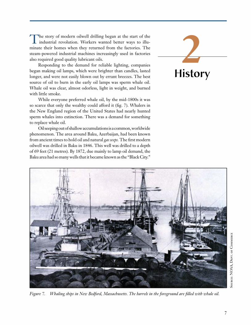
While everyone preferred whale oil, by the mid-1800s it was so scarce that only the wealthy could afford it (fig. 7). Whalers in the New England region of the United States had nearly hunted sperm whales into extinction. There was a demand for something to replace whale oil.
Oil seeping out of shallow accumulations is a common, worldwide phenomenon. The area around Baku, Azerbaijan, had been known from ancient times to hold oil and natural gas seeps. The first modern oilwell was drilled in Baku in 1846. This well was drilled to a depth of 69 feet (21 metres). By 1872, due mainly to lamp oil demand, the Baku area had so many wells that it became known as the “Black City.”
Figure 7. Whaling ships in New Bedford, Massachusetts. The barrels in the foreground are filled with whale oil.
History
Sour
ce: N
OA
A, D
ept.
of
Com
mer
ce
15
3
WALKING
BEAMBULLWHEEL
BIT
HEAVY
WEIGHTS
(SINKER BARS)
CABLE
CASING
Cable-tool drilling and rotary drilling techniques have been avail-able since people first began making holes in the ground. Rotary
rigs dominate the industry today, but cable-tool rigs drilled many wells in the past. Over 1,600 years ago, the Chinese drilled wells with various primitive yet efficient cable-tool rigs, which they continued to use into the 1940s. To quarry rocks for the pyramids, the ancient Egyptians drilled holes using hand-powered rotating bits. They drilled several holes in a line and stuck dry wooden pegs in the holes. Then they saturated the pegs with water. The swelling wood split the stone along the line made by the holes.
Most wells today are drilled with rotary rigs based on the Hamil Brothers’ design at Spindletop.
CaBLE-TOOL dRILLINgA steam-powered cable-tool rig was used by Drake and Smith to drill the Oil Creek site in Pennsylvania. The early drillers in California and elsewhere also used cable-tool rigs. The principle of cable-tool drilling is the same as that of a child’s seesaw. When a child is on each end of a seesaw, it moves it up and down. The rocking motion demonstrates the principle of cable-tool drilling.
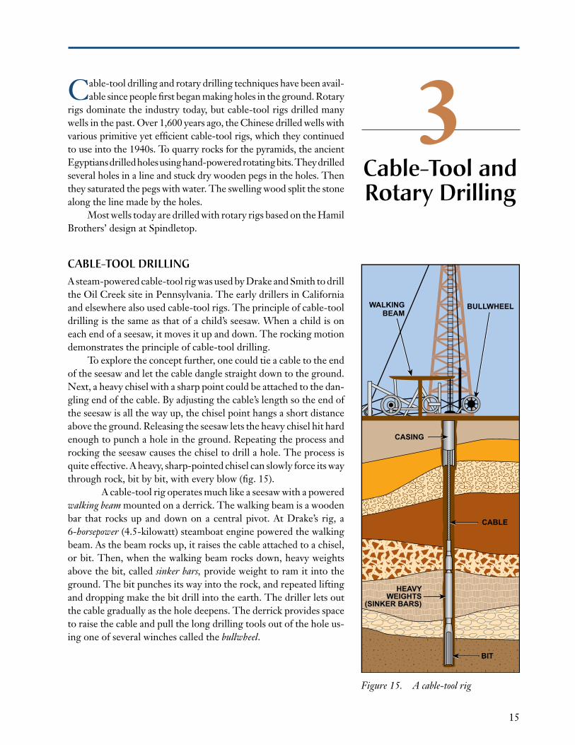
To explore the concept further, one could tie a cable to the end of the seesaw and let the cable dangle straight down to the ground. Next, a heavy chisel with a sharp point could be attached to the dan-gling end of the cable. By adjusting the cable’s length so the end of the seesaw is all the way up, the chisel point hangs a short distance above the ground. Releasing the seesaw lets the heavy chisel hit hard enough to punch a hole in the ground. Repeating the process and rocking the seesaw causes the chisel to drill a hole. The process is quite effective. A heavy, sharp-pointed chisel can slowly force its way through rock, bit by bit, with every blow (fig. 15).
A cable-tool rig operates much like a seesaw with a powered walking beam mounted on a derrick. The walking beam is a wooden bar that rocks up and down on a central pivot. At Drake’s rig, a 6-horsepower (4.5-kilowatt) steamboat engine powered the walking beam. As the beam rocks up, it raises the cable attached to a chisel, or bit. Then, when the walking beam rocks down, heavy weights above the bit, called sinker bars, provide weight to ram it into the ground. The bit punches its way into the rock, and repeated lifting and dropping make the bit drill into the earth. The driller lets out the cable gradually as the hole deepens. The derrick provides space to raise the cable and pull the long drilling tools out of the hole us-ing one of several winches called the bullwheel.
Cable-Tool and Rotary drilling
Figure 15. A cable-tool rig
21
4Rotary Rig
Types
A variety rotary drilling rigs might be used depending on the location and geography of the reservoir. Offshore, the ocean environment plays an important role in rig
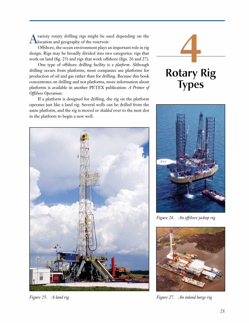
design. Rigs may be broadly divided into two categories: rigs that work on land (fig. 25) and rigs that work offshore (figs. 26 and 27).
One type of offshore drilling facility is a platform. Although drilling occurs from platforms, most companies use platforms for production of oil and gas rather than for drilling. Because this book concentrates on drilling and not platforms, more information about platforms is available in another PETEX publication: A Primer of Offshore Operations.
if a platform is designed for drilling, the rig on the platform operates just like a land rig. Several wells can be drilled from the same platform, and the rig is moved or skidded over to the next slot in the platform to begin a new well.
Figure 25. A land rig Figure 27. An inland barge rig
Figure 26. An offshore jackup rig

37
5Whether on land or offshore, and regardless of size, all rigs re-quire personnel to operate them. There are people employed
by companies involved in drilling work all over the world. They drill wells on land and ice, in swamps, and on water as small as lakes or as large as the Pacific Ocean. Drilling is demanding work, continuing 24 hours a day, 7 days a week, in all kinds of weather (fig. 46).
Drilling is also increasingly complex. The technical complexity is so great that no single company is diverse enough to perform all the required work. Consequently, many companies and individuals are involved in drilling a well, including operating companies, drill-ing contractors, and service and supply companies.
People andCompanies
Figure 46. Workers on a drilling rig
Cou
rtes
y of
En
erM
ax, I
nc.
Ph
oto
by B
ret
Bot
eler
55
6Oil and gas:
Characteristics and
Occurrence
Oil and gas are naturally occurring hydrocarbons. Two elements, hydrogen and carbon, make up a hydrocarbon. Because hydro-
gen and carbon have a strong attraction for each other, they form many compounds. The oil industry processes and refines crude hydrocarbons recovered from the earth to create hydrocarbon prod-ucts including: natural gas, liquefied petroleum gas (LPG, or hydrogas), gasoline, kerosene, diesel fuel, and a vast array of synthetic materials such as nylon and plastics.
Crude oil and natural gas occur in tiny openings of buried layers of rock. Occasionally, the crude hydrocarbons ooze to the surface in the form of a seep, or spring. More often, rock layers trap the hydrocarbons thousands of feet (metres) below the surface. To bring the trapped hydrocarbons to the surface, operating companies and drilling contractors drill wells.
NaTURaL gaS The simplest hydrocarbon is methane (CH4). it has one atom of carbon (C) and four atoms of hydrogen (H). Methane is a gas under standard conditions of pressure and temperature. Standard pressure is the pressure the atmosphere exerts at sea level, about 14.7 psia (101 kPa). Standard temperature is 60 degrees Fahrenheit, or 15.6 degrees Celsius.
Methane is the main component of natural gas. Natural gas occurs in buried rock layers usually mixed with other hydrocarbon gases and liquids. it sometimes also contains nonhydrocarbon gases and liquids such as helium, carbon dioxide, nitrogen, water, and hydrogen sulfide. Hydrogen sulfide is a poison that has a detectible sour or rotten-egg odor, even in low concentrations. Natural gas that contains hydrogen sulfide is called sour gas. After natural gas is produced or recovered, a gas processing facility removes impurities so the gas can be used by consumers.
71
7The drill Site
The location of the well, or drill site, varies as the surface geog-raphy of the earth varies. in the industry’s early days, geologists
and wildcatters were able to find oil and gas in places readily acces-sible. As people began using more hydrocarbons, the oil industry extended its search for oil and gas worldwide. Today, companies might drill wells in the frozen wilderness, remote desert, marshes, jungles, rugged mountains, and deep offshore waters. A drill site is anywhere oil and gas exists or might exist.
CHOOSINg THE SITEThe operating company considers several factors when deciding where to drill. A key factor is the company knows or believes that hydrocarbons exist in rocks beneath the site. Sometimes, an opera-tor drills a well in an existing field to increase production from it. in other cases, an operator drills a well on a site where no one has previously found oil or gas.
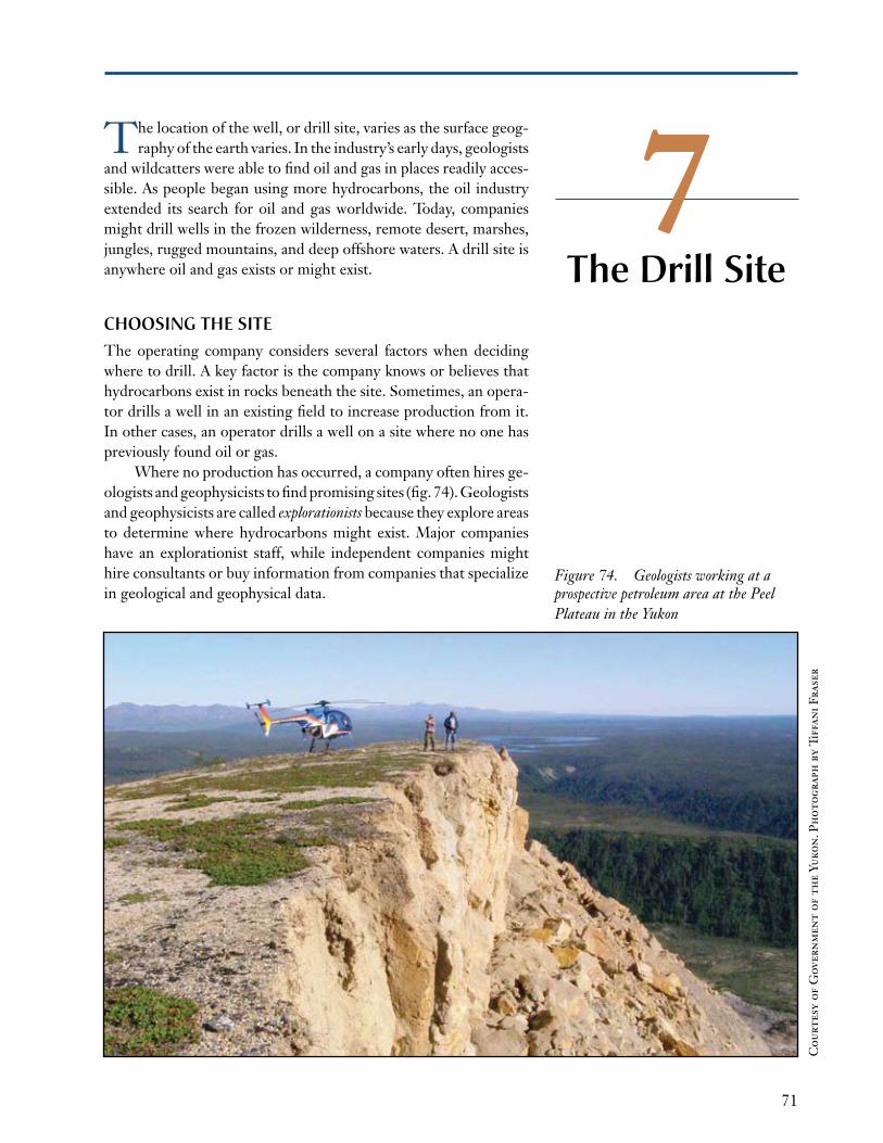
Where no production has occurred, a company often hires ge-ologists and geophysicists to find promising sites (fig. 74). Geologists and geophysicists are called explorationists because they explore areas to determine where hydrocarbons might exist. Major companies have an explorationist staff, while independent companies might hire consultants or buy information from companies that specialize in geological and geophysical data.
Cou
rtes
y of
Gov
ern
men
t of
th
e Yu
kon
. Ph
otog
raph
by
Tiff
ani F
rase
r
Figure 74. Geologists working at a prospective petroleum area at the Peel Plateau in the Yukon

85
8Rigging Up
Rigging up an offshore drilling rig is usually not as complicated as rigging up a land rig. Most offshore rigs can be moved over
water with almost no need to disassemble major parts. Onsite, the offshore rig is stabilized by placing rig supports on the ocean floor for bottom-supported rigs or, by anchors, anchor chains, and wire or polyester rope for floaters. Only the dynamically positioned floaters require no additional support to stay in position during drilling.
To move most land rigs, crewmembers must disassemble many of its components. Disassembly is required so the parts can be transported to the next location and then reassembled. For safety, rigging up usually takes place only during daylight hours. Even with lighting after dark, there is too much heavy equipment to move safely during rig-up.
On most land rigs during rigging up, the rig parts are put back together so the rig can drill a hole. it involves unloading and hooking up the rig engines, the mud tanks and pumps, and other equipment on the site. One of the last steps, and one of the more dramatic, is raising the mast from horizontal—the position in which it was transported—to the vertical drilling position. The first rig component positioned by the crew is the rig’s substructure, which is the base, or foundation.
SUBSTRUCTURESA substructure is the framework located directly over the hole; it is the foundation of the rig. The bottom of the substructure rests on level ground. The crew places a work platform on top of the substructure called the rig floor. The substructure raises the rig floor to approximately 10 to 40 feet (3 to 12 metres) above the ground. Elevating the rig floor provides room under the rig for special high-pressure valves and a blowout preventer (BOP) stack that the crew connects to the top of the well’s casing. The exact height of a substructure depends on the space needed for this equipment. A cellar also provides more space for the equipment.

93
9Rig
Components
The main function of a rotary rig is to drill a hole in the ground, or to make hole. Making hole with a rotary rig requires quali-
fied personnel and a large amount of equipment. There are four main categories of equipment systems used in making hole: power, hoisting, rotating, and circulating.
POWER SySTEMEvery rig needs a source of power to run the hoisting, circulating, and rotating equipment. in the early days of drilling, steam engines powered most rigs. in the 1860s, Colonel Drake powered his rig with a wood-fired steamboat engine. Until the 1940s and 50s, steam engines drove almost every rig (fig. 95).
Steam is a tremendous power source. For example, steam cata-pults are used today on modern aircraft carriers to launch aircraft. The major problem with using steam power on drilling rigs was that the boilers were heavy and difficult to move. Also, the steam lines to the steam engines were heavy and withstood high pressures and temperatures. Steam power also required large volumes of water and fuel.
Figure 95. In the foreground is a coal-fired boiler that made steam to power the cable-tool rig in the background.
135
10Normal drilling
Operations
Normal drilling operations include drilling the hole and adding a new joint of pipe as the hole deepens. it also involves tripping
the drill string out the hole to put on a new bit and then running it back to the bottom (making a round trip). Other key steps include running and cementing the large-diameter steel casing used to seal selected intervals of the hole.
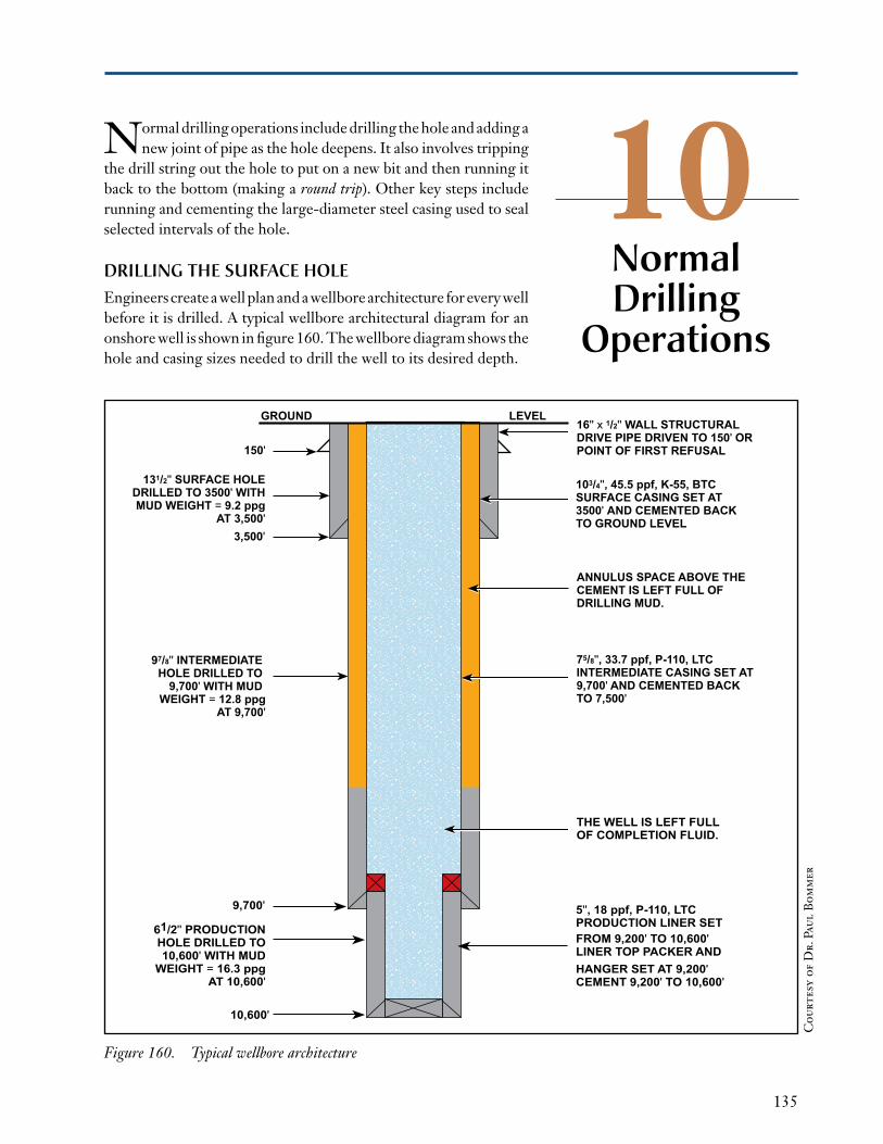
dRILLINg THE SURfaCE HOLEEngineers create a well plan and a wellbore architecture for every well before it is drilled. A typical wellbore architectural diagram for an onshore well is shown in figure 160. The wellbore diagram shows the hole and casing sizes needed to drill the well to its desired depth.
Figure 160. Typical wellbore architecture
GROUND LEVEL
150'
3,500'
9,700'
10,600'
131/2'' SURFACE HOLEDRILLED TO 3500' WITHMUD WEIGHT = 9.2 ppg
AT 3,500'
97/8'' INTERMEDIATE HOLE DRILLED TO
9,700' WITH MUD WEIGHT = 12.8 ppg
AT 9,700'
61/2'' PRODUCTIONHOLE DRILLED TO10,600' WITH MUD
WEIGHT = 16.3 ppgAT 10,600'
THE WELL IS LEFT FULLOF COMPLETION FLUID.
5'', 18 ppf, P-110, LTC PRODUCTION LINER SET FROM 9,200' TO 10,600'LINER TOP PACKER AND HANGER SET AT 9,200' CEMENT 9,200' TO 10,600'
ANNULUS SPACE ABOVE THE CEMENT IS LEFT FULL OF DRILLING MUD.
75/8'', 33.7 ppf, P-110, LTCINTERMEDIATE CASING SET AT9,700' AND CEMENTED BACKTO 7,500'
16'' x 1/2'' WALL STRUCTURAL DRIVE PIPE DRIVEN TO 150' OR POINT OF FIRST REFUSAL
103/4'', 45.5 ppf, K-55, BTCSURFACE CASING SET AT 3500' AND CEMENTED BACK TO GROUND LEVEL
Cou
rtes
y of
Dr.
Pau
l B
omm
er
163
11formationEvaluation
Formation evaluation is the process used by operators to determine if rock layers contain hydrocarbons. Formation evaluation can
determine if sufficient quantities of hydrocarbons are present and if the rock has enough permeability to allow a commercial comple-tion. The techniques addressed in this chapter are the examination of cuttings and drilling mud, well logging, drill stem testing, and coring.
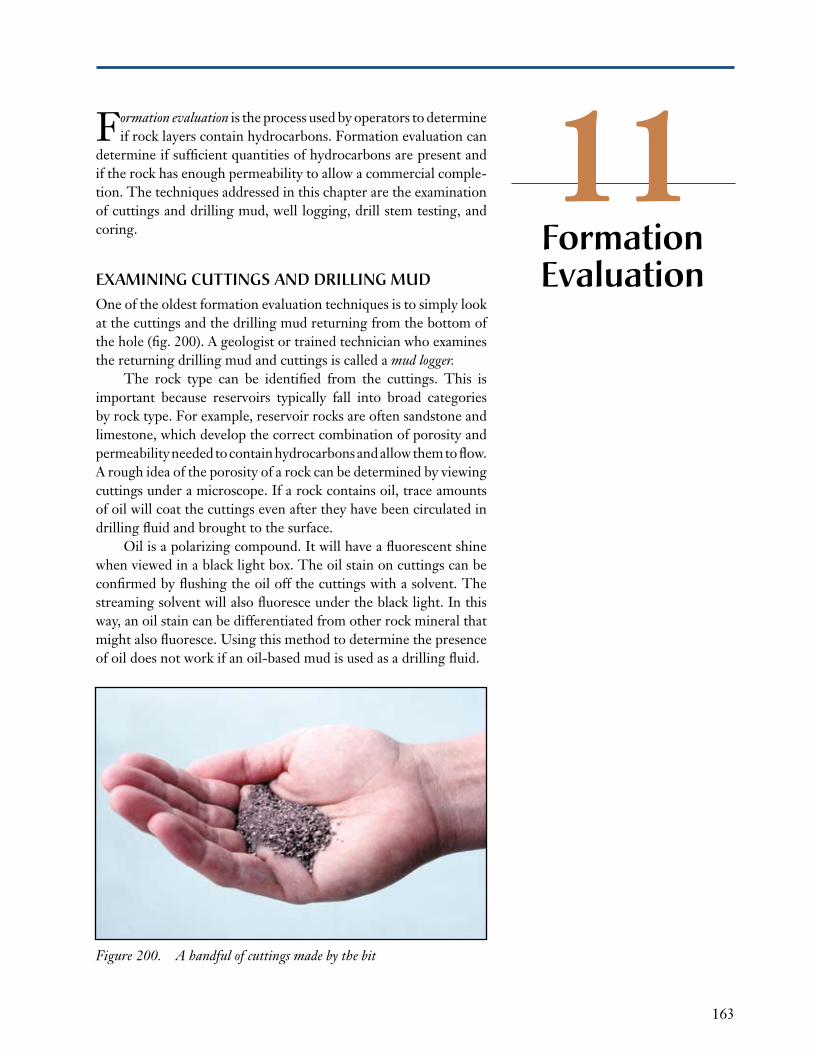
EXaMININg CUTTINgS aNd dRILLINg MUdOne of the oldest formation evaluation techniques is to simply look at the cuttings and the drilling mud returning from the bottom of the hole (fig. 200). A geologist or trained technician who examines the returning drilling mud and cuttings is called a mud logger.
The rock type can be identified from the cuttings. This is important because reservoirs typically fall into broad categories by rock type. For example, reservoir rocks are often sandstone and limestone, which develop the correct combination of porosity and permeability needed to contain hydrocarbons and allow them to flow. A rough idea of the porosity of a rock can be determined by viewing cuttings under a microscope. if a rock contains oil, trace amounts of oil will coat the cuttings even after they have been circulated in drilling fluid and brought to the surface.
Oil is a polarizing compound. it will have a fluorescent shine when viewed in a black light box. The oil stain on cuttings can be confirmed by flushing the oil off the cuttings with a solvent. The streaming solvent will also fluoresce under the black light. in this way, an oil stain can be differentiated from other rock mineral that might also fluoresce. Using this method to determine the presence of oil does not work if an oil-based mud is used as a drilling fluid.
Figure 200. A handful of cuttings made by the bit
173
12Once the formation evaluation is done, the operator must decide if the well should be completed as a producing oil or gas well.
if the well does not contain hydrocarbons, or not enough to pay for the completion, the well will be plugged and abandoned (P&A).
PLUggINg aNd aBaNdONINg a WELLTo P&A a well, the drilling rig pumps several cement plugs through the drill pipe. The cement plugs are used to isolate and seal unprofitable hydrocarbon zones from nonhydrocarbon-bearing zones and to seal freshwater zones from saltwater-bearing zones. The intervals between cement plugs are left full of drilling mud. At this time, it might be pos-sible to cut off and recover some of the intermediate casing string (if one is present) for use in other wells. The surface casing string is always left in place and sealed at the bottom and top by either cement plugs or a combination of mechanical and cement plugs. The surface casing will be cut off below the ground level or mud line and a cap placed on the stub. if the well is on land, the well site will be environmentally restored after the drilling rig has been moved off the location.
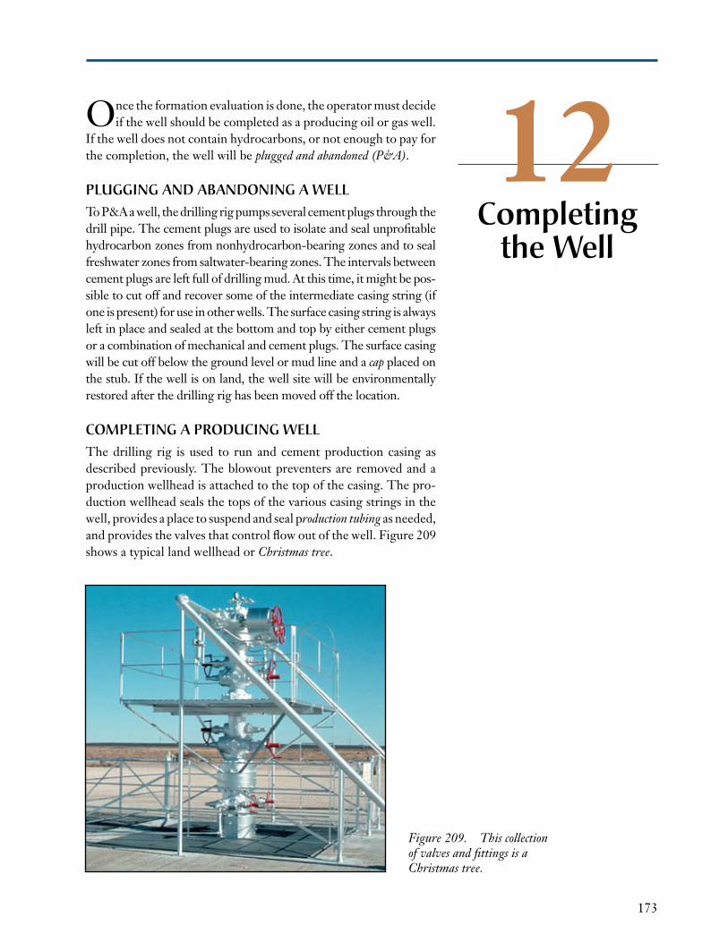
COMPLETINg a PROdUCINg WELLThe drilling rig is used to run and cement production casing as described previously. The blowout preventers are removed and a production wellhead is attached to the top of the casing. The pro-duction wellhead seals the tops of the various casing strings in the well, provides a place to suspend and seal production tubing as needed, and provides the valves that control flow out of the well. Figure 209 shows a typical land wellhead or Christmas tree.
Figure 209. This collection of valves and fittings is a Christmas tree.
Completing the Well

179
13There are several special operations used in oilwell drilling: directional drilling, fishing, and well control.
dIRECTIONaL dRILLINgNo well is ever perfectly vertical. Even wells meant to be drilled vertically will wander a few degrees from vertical and move in dif-ferent directions. Routine measurements are taken during drilling to determine if a well is deviating from vertical by more than the allowed amount (normally less than 5 degrees). if so, careful drilling practices, such as changing the placement of stabilizers in the BHA or adjusting the rotary speed or weight on bit, will bring the well back within the tolerances normally allowed for vertical wells.
Directional drilling is used when a well is intentionally devi-ated to reach a bottomhole location (BHL) that is different from the surface location (SL). Directional drilling is done for many reasons. The BHL might be under an obstruction such as a building or lake where rigging up over the required BHL is not possible. it might be necessary to drill several wells from a fixed place, such as an offshore platform or an onshore drilling island (fig. 215), to different bottomhole locations.
Part of an existing well might become blocked with lost drill-ing tools that are unrecoverable, or a well might have been drilled into an unproductive part of the reservoir. it is possible to set a plug in the lower part of the well and deviate, or kick off, the well to a new BHL. Some reservoirs are more efficiently produced by wells drilled at a very high angle. These wells are known as hori-zontal wells because the inclination angle from vertical reaches 90 degrees or more.
Older directional drilling methods placed inclined wedges, called whipstocks, in the well to force the bit to move in the de-sired direction. in soft sediments, it is possible to place a large bit nozzle or jet in the desired direction and simply erode the well’s starting path. Although time consuming, these methods are still used at times.
The two faster and often more reliable methods of directional drilling are:
• Slidedrilling with a motor• Drillingwitharotary steerable assembly
Special Operations
Figure 215. Several directional wells tap an offshore reservoir.
DIRECTIONAL
WELL
189
14Rig Safety and Environmental
Concerns
Safety training is part of everyday life for all hands on a drilling rig. There are safety meetings at the beginning of every tour
and before each new part of a job. Outside training, such as well control schools and helicopter safety training for offshore crews, is also required for drilling personnel. The equipment used to drill a well is technical and complex, and those who run the equipment must be well trained.
The international Association of Drilling Contractors (iADC) keeps a list of detailed statistics on accident rates in the drilling industry. The annual statistics can be viewed at iADC’s Web site (www.iadc.org). One statistic is the total number of any type of accident that occurs for every one million man-hours worked. This number has declined slightly from 2002–2007 at an average of 11.16 accidents per one million man-hours worked. A normal number of hours one person might work on a drilling rig is about 3,100 man-hours in one year. So, a five-person crew will work roughly 15,500 man-hours in one year. Using the average accident rate shown above, the number of accidents that might be estimated to occur in one year in the five-person crew is 0.18 or less than one. This calculation suggests the average drilling crewmember is a safe worker.
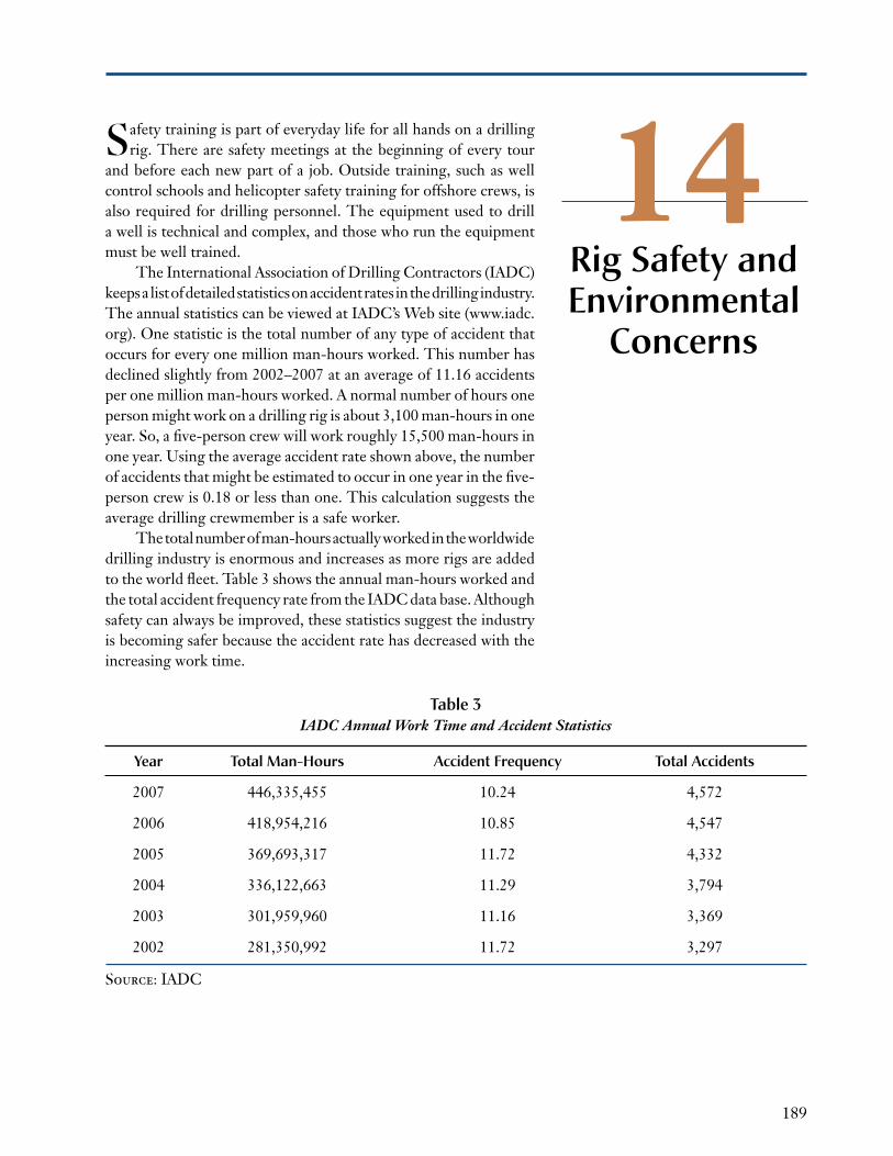
The total number of man-hours actually worked in the worldwide drilling industry is enormous and increases as more rigs are added to the world fleet. Table 3 shows the annual man-hours worked and the total accident frequency rate from the iADC data base. Although safety can always be improved, these statistics suggest the industry is becoming safer because the accident rate has decreased with the increasing work time.
Table 3 IADC Annual Work Time and Accident Statistics
year Total Man-Hours accident frequency Total accidents
2007 446,335,455 10.24 4,572
2006 418,954,216 10.85 4,547
2005 369,693,317 11.72 4,332
2004 336,122,663 11.29 3,794
2003 301,959,960 11.16 3,369
2002 281,350,992 11.72 3,297
Source: IADC

191
15Drilling has developed into a specialized and technologically advanced business. The size of the equipment is enormous.
The technical challenges to overcome as wells become deeper and are drilled in increasingly hostile environments are equally enormous. The technology of the most advanced drilling rig is computer-controlled and can be monitored from any office in the world. The guidance systems used in directional drilling rival those found on modern jet aircraft or spacecraft.
The energy business is the largest business in the world. This will continue because the standard of living in most countries is now tied to the ability to find and use energy efficiently. Well drill-ing continues to be an important part of the efficient use of energy, regardless of whether the well is producing hydrocarbons or water, or permanently disposing wastes by injecting them into deep layers in the earth.
The drilling industry must have people who are trained, moti-vated, and, most importantly, interested in the business, the science, and the art of drilling.
Conclusion