a proposed sustainable sanitation system for the zwelitsha ... · informal settlement in...
TRANSCRIPT

A Proposed Sustainable Sanitation System for the Zwelitsha section of Langrug
Informal Settlement in Stellenbosch Municipality South Africa
A Thesis
submitted to the Faculty
of
WORCESTER POLYTECHNIC INSTITUTE
in partial fulfillment of the requirements for the
Degree of Master of Science
in Environmental Engineering
by
________________________________________
Edwin Muñiz
May 2013
APPROVED:
_______________________________________
Professor Jeanine D. Plummer, Major Advisor
_______________________________________
Professor Scott Jiusto, Interdisciplinary Advisor

ii
Abstract
Globally, inadequate access to safe water and sanitation services, coupled with poor
hygiene practices, kills and sickens thousands of children every day and leads to impoverishment
and diminished opportunities for thousands more. The United Nations (UN), has recognized
water, sanitation and hygiene (WaSH) as major issues that greatly affect the global poor. Under
its Millennium Development Goals, the UN has set targets for addressing these issues. Namely,
the UN aims to reduce by 50% the proportion of the global population without sustainable access
to safe drinking water and basic sanitation by 2015. In 2010, the target of halving the proportion
of people without access to improved sources of water was met five years ahead of schedule.
Despite progress, 2.5 billion people in developing countries still lack access to improved
sanitation facilities. As a result, the vision of WaSH is incomplete. Often, lack of access to basic
sanitation is a daily reality for persons residing in informal settlements. The focus of this thesis
was an area called Zwelitsha in the informal settlement of Langrug. Located in Stellenbosch
Municipality near Cape Town, South Africa, Zwelitsha currently has few functional toilets for its
604 residents. As a result, persons resort to open defecation, contributing to environmental
contamination and possible disease transmission throughout the settlement. Thus, sanitation is a
significant need for Zwelitsha. Advancing the work of the Cape Town Project Centre (CTPC) – a
center location within the Interdisciplinary and Global Studies Division of Worcester
Polytechnic Institute – this thesis aimed to address the shortcomings in the provision of
sanitation services within Zwelitsha. Through research, urine divergent dehydration and
composting toilet systems were found to be the most technically feasible and applicable for
meeting the sanitation needs of Zwelitsha. Favorable characteristics of these systems include
independence from a connection to water pipes, sewerage, and energy sources and the generation
of usable agricultural products. Both household level and community level options were
proposed in this thesis. Proposed systems can be integrated into a large-scale WaSH facility with
additional services such as water taps, sinks, toilets, showers, laundry stations, recreational areas,
gardens, and salons for local business.

iii
Acknowledgments
I would like to thank Professor Jeanine D. Plummer, Environmental Engineering
Program Director and Associate Professor of the Civil and Environmental Engineering
Department who has served as my Major Advisor over the past year. Professor Plummer has
provided invaluable feedback throughout the process. Her deliberation, critical thinking, and
attention to detail have been integral to the formation of this thesis. I would also like to thank
Professor Scott Jiusto, Cape Town Project Centre Director and Associate Professor of the
Interdisciplinary & Global Studies Division who has served as my Interdisciplinary Advisor.
Professor Jiusto has shared his past work and experiences in Cape Town, which along with his
ardent vision have inspired the research of this thesis. I would like to thank Worcester
Polytechnic Institute and the Civil and Environmental Department for providing me with all its
resources including a desk to conduct my research. Lastly, I would like to thank all my family
and friends who have supported and bolstered me toward this final product.

iv
Table of Contents Abstract ............................................................................................................................... ii
Acknowledgments.............................................................................................................. iii
List of Figures .................................................................................................................... vi
List of Tables ................................................................................................................... viii
Chapter 1: Introduction ....................................................................................................... 1
1.1 Water, Sanitation and Hygiene (WaSH) ................................................................... 1
1.2 Informal Settlements ................................................................................................. 2
1.3 Cape Town ................................................................................................................ 3
1.4 Zwelitsha ................................................................................................................... 5
1.5 Knowledge Gap/Thesis Goals ................................................................................... 6
Chapter 2: Toilet System Evaluation .................................................................................. 8
2.1 Composting Toilet Systems ...................................................................................... 8
2.2 Urine Diversion Toilet Systems ................................................................................ 9
2.2.1 Urine Diversion Dehydration Toilet (UDDT) Systems .................................... 10
2.2.2 Urine Diversion (UD) Toilet Systems .............................................................. 14
2.3 Incinerating Toilet Systems ..................................................................................... 15
2.3.1 Electric-Powered Incinerating Toilet Systems ................................................. 15
2.3.2 Gas-Fired Incinerating Toilet Systems ............................................................. 17
2.4 Oil Recirculating/Flush Toilet Systems .................................................................. 18
2.5. Comparative Analysis of Toilet Sanitation System Selection ............................... 19
2.5.1 Toilet Systems Applicable to Zwelitsha ........................................................... 21
Chapter 3: Products from Human Excreta ........................................................................ 24
3.1 Sterile Urine Fertilizer ............................................................................................. 24
3.2 Fecal Compost ......................................................................................................... 28
3.2.1 Insulation and Cover Material .......................................................................... 32
3.2.2. Proper Maintenance and Monitoring ............................................................... 33
Chapter 4: Sanitation System Proposal ............................................................................. 35
4.1 Household Level Sanitation System ....................................................................... 35
4.1.1 The Loveable Loo ............................................................................................. 35
4.1.2 UDDT for African Context............................................................................... 37
4.2 Sanitation System for Integration into Large-Scale Sanitation System .................. 40
Chapter 5: Conclusions and Recommendations ............................................................... 55
5.1 Conclusions ............................................................................................................. 55

v
5.2 Recommendations for Future Work ........................................................................ 55
5.2.1 Integrate Sanitation into a Full-Service WaSH Facility ................................... 56
5.2.2 Cultivate User Awareness ................................................................................ 56
5.2.3 Enlist Local Farmers in Excreta Reuse............................................................. 56
5.2.4 Perform a Financial and Economic Analysis of System .................................. 57
References ......................................................................................................................... 58
Appendix A: Constructing a Loveable Loo ...................................................................... 66
Appendix B: Constructing a UDDT Locally .................................................................... 68

vi
List of Figures
Figure 1. Diagram of a Typical Single-Chambered Composting Toilet System ........................... 8 Figure 2. Left: Indoor UDDT (pedestal type) in Johannesburg, South Africa.
Right: UDDT Squatting Pan in Bangalore, India, with three holes: the area in the
front is for anal washing, middle is for feces and back is for urine. ............................. 11
Figure 3. Waterless Urinals for Men. Left: Centaurus model of Keramag company.
Right: Plastic Urinal from Addicom, South Africa with EcoSmellstop device. .......... 12 Figure 4. UD Flush Toilets. Left: Gustavsberg (in Meppel, the Netherlands). Right:
Dubbletten (in Stockholm, Sweden). ........................................................................... 14 Figure 5. Diagram of a Typical Electric-powered Incinerating Toilet System........................... 16
Figure 6. Step-by-step use of Electric-powered Toilet System .................................................. 16 Figure 7. Left: STORBURN Unit. Right: Complete System with Propane Hookup and
Ventilation System. ...................................................................................................... 17 Figure 8. Oil Recirculating/Flush System ................................................................................... 18
Figure 9. Closing the Nutrient Loop ........................................................................................... 24 Figure 10. Loveable Loo ............................................................................................................... 36
Figure 11. Front View of Vault with Toilet Slab Placed on Top .................................................. 37 Figure 12. View from Behind Vault Showing Slanted Concrete Access Slab ............................. 37 Figure 13. View from Behind Vault Showing Removed Access Slab, 20 L Collection Bucket
within Vault, and Superstructure on Top Enclosing Toilet Pedestal for Privacy ........ 38
Figure 14. Toilet Pedestal with Urine-Diversion Pipe .................................................................. 38
Figure 15. Emptying Bucket Contents into Shallow Pit Composter ............................................ 39 Figure 16. Three Cement Jars: One with an Painted Concrete Cover (left); One with
Standard Cement Lid (center); One with Plants Growing from it (right) .................... 39
Figure 17. Twin Pit Composter ..................................................................................................... 40
Figure 18. Toilet side of MobiSan: 13 UDDTs separated by gender and age .............................. 41 Figure 19. Urinal side of MobiSan: 12 waterless men’s urinals ................................................... 41 Figure 20. Schematic of UDDT Toilet Unit: Top View (Top Left); Angled Top View (Top
Right); Front View (Bottom Left); Side View (Bottom Middle); Side
Cross-sectioned View (Bottom Right) ......................................................................... 43 Figure 21. Schematic of Facility Toilet System with Important Design Features ........................ 44 Figure 22. Rendered Version of Toilet System ............................................................................ 44 Figure 23. Schematic of Compost Facility: Rainwater Harvesting Side (left); Compost
Loading Side (right) ..................................................................................................... 46
Figure 24. Fecal Matter Volume Calculation with Associated Assumptions ............................... 47
Figure 25. Aerial View (top), Front View (bottom left), and Side View (bottom right) for
Compost Facility .......................................................................................................... 49 Figure 26. Composting Facility on Concrete Slab (Compost Loading Side) ............................... 50 Figure 27. Compost Facility on Soil (Rainwater Harvesting Side) .............................................. 50 Figure 28. Schematic of Urine Storage Tank with Important Design Features:
Aerial View (top); Side View (bottom) ....................................................................... 51
Figure 29. Urine Storage Tank with Access Lid Open ................................................................. 52 Figure 30. Urine Storage Tank with Closed Access Lid .............................................................. 52 Figure 31. Urine Volume Calculations with Associated Assumptions......................................... 53

vii
Figure 32. Toilet Facility (middle) with Parallel Urine Storage Tanks (left) and Composting
Station (right) ............................................................................................................... 54 Figure 33. View of Composting Station and Toilet Facility looking into Toilet Stalls ................ 54 Figure 34. Visual Instruction for Constructing a Loveable Loo ................................................... 67
Figure 35. Brick Mould for Concrete Slab ................................................................................... 68 Figure 36. Brick Mould for Toilet Slab with Bucket and Metal Cylinder for Pedestal and
Vent Pipe Space ........................................................................................................... 68 Figure 37. Vault Using Bricks on Their Edge .............................................................................. 69 Figure 38. Vault with Concrete Lintel above 20 Litre Bucket ..................................................... 69
Figure 39. Fitting Vault Access Slab ............................................................................................ 69 Figure 40. Front View of Vault with Toilet Slab Placed on Top .................................................. 70 Figure 41. Cutting off the Bucket Base ........................................................................................ 70 Figure 42. Marking base for Cutting............................................................................................. 70
Figure 43. Cut Base Halves .......................................................................................................... 71 Figure 44. Placing Urine Diverter (Cut Base Half) Half-way up Bucket at an Angle ................. 71
Figure 45. Attached Diverter with Wire ....................................................................................... 71 Figure 46. Fitting Pipe Bend to Bucket ........................................................................................ 71
Figure 47. Inside View of the Fitted Pipe Bend............................................................................ 72 Figure 48. Using Hot Wire to Make a Hole through the Plastic Toilet Seat Ribs ........................ 72 Figure 49. Toilet Seat with a Threaded Loop of Wire .................................................................. 72
Figure 50. Concrete Added to the Toilet Seat ............................................................................... 73 Figure 51. Bucket Fitted to Toilet Seat ......................................................................................... 73
Figure 52. Bent Wire around Toilet Seat ...................................................................................... 73 Figure 53. Concrete Added Half-way up Bucket .......................................................................... 74 Figure 54. Concrete Added to the Second Half of Bucket ........................................................... 74
Figure 55. Bucket and Seat within Base Mould ........................................................................... 74
Figure 56. Wire Added for Reinforcement ................................................................................... 75 Figure 57. Completely Cemented Pedestal Curing ....................................................................... 75 Figure 58. Urine Diverter Sealed from Bottom ............................................................................ 75
Figure 59. Urine Diverter Sealed from Top .................................................................................. 76 Figure 60. Attached Urine Pipe .................................................................................................... 76
Figure 61. Urine Pipe Led to Rear of Toilet ................................................................................. 76 Figure 62. Painted Pedestal ........................................................................................................... 76
Figure 63. Installed UDDT on Slab within Straw Superstructure ................................................ 77 Figure 64. Urine Pipe Led to Banana Tree ................................................................................... 77 Figure 65. View of Collection Bucket for Feces within Vault after Removing Access Slab ....... 77

viii
List of Tables
Table 1. Sanitation and Water Targets and Current Conditions in the Informal Settlements of
Cape Town, South Africa ................................................................................................. 5 Table 2. Toilet Systems and Evaluative Criteria .......................................................................... 22 Table 3. Nitrogen demand of different plants ............................................................................... 25
Table 4. Estimated excretion of nutrients from urine per capita in different countries ................ 25 Table 5. NPK ratio for urine in different countries ....................................................................... 26 Table 6. Recommended guideline storage times for urine mixture based on estimated pathogen
content and recommended crop for larger systems ....................................................................... 27 Table 7. Average Chemical Composition of Fresh and Stored Urine .......................................... 28

1
Chapter 1: Introduction
The focus of thesis was the selection of a technically-feasible and sustainable sanitation
system for application in the informal settlement of Zwelitsha, located in Cape Town, South
Africa. This chapter introduces the global water, sanitation, and hygiene (WaSH) deficit,
informal settlements, and Cape Town, South Africa to orient the reader to the WaSH problem.
Then, WaSH problems in Zwelitsha, an informal settlement in Cape Town, are discussed. Lastly,
the goals of this thesis are presented. The remaining chapters present sanitation systems and
propose a system for use in Zwelitsha.
1.1 Water, Sanitation and Hygiene (WaSH)
Beginning in 1990, the United Nations (UN) lead a decade-long series of conferences
focused on issues of the global poor. In an effort to end extreme poverty globally by 2015, the
UN agreed on eight goals Millennium Development Goals at the Millennium Summit in 2000.
These goals, which built on the UN-led conferences commenced in 1990 included:
1. Eradicate extreme poverty and hunger;
2. Achieve universal primary education;
3. Promote gender equality and empower women;
4. Reduce child mortality;
5. Improve maternal health;
6. Combat HIV/AIDS, malaria and other diseases;
7. Ensure environmental sustainability; and
8. Global partnership for development (UN, 2013).
The UN realized that in order to meet these goals, several interim targets must be met.
Under the seventh goal of ensuring environmental sustainability, a target was set to reduce by
50% the proportion of the population without sustainable access to safe drinking water (UN,
2013). World leaders failed to recognize sanitation as a target at the Summit. In reaction, the
Global WaSH (Water Sanitation and Hygiene) Campaign was launched in 2001 (WSCC, 2013).
Inadequate access to safe water and sanitation services, coupled with poor hygiene practices,
kills and sickens thousands of children every day and leads to impoverishment and diminished
opportunities for thousands more (UNICEF, 2013). Recognition of this linkage among water,
sanitation, and hygiene led to the 2001 Campaign which sought to mobilize support for bringing
sanitation and hygiene to the global agenda along with safe water access.
As a result of the WaSH Campaign, sanitation, initially left out of the plan, was added as
a target to the Millennium Development Goals at the 2002 World Summit for Sustainable
Development (WSCC, 2013). Specifically, sanitation was coupled with the safe drinking water
target under the seventh goal of ensuring environmental sustainability. The target was set to
reduce by 50% the proportion of the population without sustainable access to safe drinking water
and basic sanitation by 2015 (UN, 2013) Through the UN, Millennium Development Goals were
agreed upon by world leaders in 1990. As a result, targets are set with respect to the global rates
of 1990. Even though it was added following the 2002 World Summit for Sustainable
Development, the target of reducing by 50% the proportion of the population without sustainable

2
access to basic sanitation is also set against the 1990 global rate. The 1990 global rates were 76%
and 49% for the portion of the population with sustainable access to safe drinking water and
basic sanitation, respectively (UN, 2012; WHO, 2013a). Thus, to achieve the targets, 88% and
75% of the global population would need to have sustainable access to safe drinking water and
basic sanitation by 2015.
In 2010, the target of halving the proportion of people without access to improved
sources of water was met five years ahead of schedule. Between 1990 and 2010, more than two
billion people gained access to improved drinking water sources. The proportion of people using
an improved water source rose from 76% in 1990 to 89% in 2010. Over 40% of all people
without improved drinking water live in sub-Saharan Africa. Eleven percent of the global
population—783 million people—remains without access to an improved source of drinking
water. At the current pace of investment and barring additional interventions, 605 million people
will still lack coverage in 2015 (UN, 2012). Access to improved sanitation facilities increased
from 36% in 1990 to 56% in 2010 in developing regions as a whole. The greatest progress was
achieved in Eastern and Southern Asia.
Despite progress, 2.5 billion in developing countries still lack access to improved
sanitation facilities. As a result, the vision of WaSH is incomplete. Working together,
Governments, the UN family, the private sector and civil society are making significant advances
in providing improved sources of drinking water, but sanitation, and consequently hygiene, are
seeing less progress. At current rates of investment and without additional interventions, by
2015, it is estimated that 67% of the global population will have sanitation coverage, well short
of the 75% needed to achieve the Millennium Development Goals target (UN, 2012).
Daily, entire communities are exposed to the considerable health and environmental
hazards of inadequate human waste disposal (UN, 2012). About 2 million people die every year
due to diarrhoeal diseases; most of them are children less than 5 years of age. The most affected
are the populations in developing countries, living in extreme conditions of poverty, normally
peri-urban dwellers or rural inhabitants (WHO, 2013b).
There are a number of factors that contribute to WaSH issues. These include lack of
priority by responsible parties (such as governments, politicians, and utility providers) given to
WaSH-related issues, lack of financial resources, lack of sustainability of water supply and
sanitation services, poor hygiene behaviours, and inadequate sanitation in public places including
hospitals, health centers and schools. Providing access to sufficient quantities of safe water, the
provision of facilities for sanitary disposal of excreta, and introducing sound hygiene behaviours
are of capital importance to reduce the burden of disease caused by these risk factors (WHO,
2013b).
1.2 Informal Settlements
The UN Habitat Program defines informal settlements as:
1. residential areas where a group of housing units has been constructed on land to which
the occupants have no legal claim, or which they occupy illegally; and
2. unplanned settlements and areas where housing is not in compliance with current
planning and building regulations (WHO, 1999).

3
Other widely used terms for informal settlements include unplanned settlements, squatter
settlements, marginal settlements, unconventional dwellings, non-permanent structures,
inadequate housing, and slums (WHO, 1999).
Rapid urbanization and inadequate capability to meet the housing needs of people in
urban areas have contributed to the development of informal settlements on a global scale
(WHO, 1999). Persons residing within these informal settlements often face challenging living
conditions. Sanitation, hygiene behaviour, food storage facilities and drinking water quality are
often poor, exposing inhabitants to a wide range of pathogens. Houses may even act as breeding
grounds for insect vectors, posing great health risks. Additionally, access to healthcare and other
services are often limited (WHO, 1999). Furthermore, since informal settlements are unguided
by urban planning, street grids, roads, and utility infrastructure are often nonexistent and, if
present, are inadequately provisioned contributing to the issues of overcrowding. Overcrowding
can contribute to stress, violence and increased problems of drugs and other social problems
(WHO, 1999). The poor conditions within informal settlements have many contributing factors
that must be addressed to improve living standards for inhabitants.
The reality of informal settlements is so dismal that world leaders (through the UN)
believe that changing this reality is an integral step in ending extreme global poverty.
Consequently, the UN made improving the lives of informal settlement dwellers a target under
the environmental sustainability Millennium Development Goal. Namely, the target is to
achieve, by 2020, a significant improvement in the lives of at least 100 million slum (informal
settlement) dwellers (UN, 2013). In 2012, this target was met. Between 2000 and 2012, the share
of urban slum residents in the developing world declined from 39% to 33%. Over 200 million
residents gained access to improved water sources, improved sanitation facilities, or durable or
less crowded housing, exceeding the Millennium Development Goal target. Still, 863 million
people were estimated to be living in slums in 2012 (UN, 2013). In addition, some sources
(HDA, 2012; Carr-Hill, 2013) suggest that estimates of slum populations are significantly
undercounted.
1.3 Cape Town
According to a 2011 census conducted by Statistics South Africa, nearly 15% of the
South African population of 51 million people lives in informal settlements (StatsSA, 2011;
ECSECC, 2012). South Africa is subdivided into nine provinces: Eastern Cape; Free State;
Gauteng; KwaZulu-Natal; Limpopo; Mpumalanga; Northern Cape; North West; and Western
Cape. The legislative capital of South Africa is Cape Town, which is located in the Western
Cape province. Cape Town is home to the largest informal settlement in Africa, Khayelitsha with
over 40,000 informal shack dwellings. Enumeration projects estimate that there are
approximately 300 informal settlements like Khayelitsha within the City of Cape Town alone
(Rodriques et al., 2006; HDA, 2012). According to census data obtained by the Strategic
Development Information and GIS Department of the City of Cape Town in 2011, there are
approximately 235,000 informal shack dwellings in the informal settlements of Cape Town. The
data estimated an average household size of 3.5 persons, which means that approximately
823,000 live in the informal settlements of Cape Town (CCT, 2012a). Despite being the second
largest contributor to the South African Gross Domestic Product, Cape Town struggles with the
challenges of informal settlements (CCT, 2012b). Among the challenges found in these
settlements is the provision of WaSH services.

4
Through the Water and Sanitation Services Department of the Western Cape Province,
the City of Cape Town has both the constitutional responsibility for water services and the
operational responsibility, as the Water Services Provider (CCT, 2012b). Therefore, the City of
Cape Town is responsible for the provision of basic water supply and sanitation for the province.
According to the Water and Sanitation Services Department, “basic water supply” comprises of
the following:
1) The provision of appropriate education in respect of effective water use;
2) A minimum quantity of potable water of 25 litres per person per day;
3) At a minimum flow rate of not less than 10 litres per minutes;
4) Within 200 metres of a household; and
5) With an effectiveness of not more than 7 days interruption supply to any consumer per
year.
Similarly, the department states that “basic sanitation” has two components. The first is
the provision of appropriate health and hygiene education. The second is a toilet which is safe,
reliable, environmentally sound, easy to keep clean, provides privacy and protection against the
weather, is well ventilated, keeps smells to a minimum and prevents the entry and exist of flies
and other disease-carrying pests (CCT, 2012c). Regarding water supply and sanitation, standard
provision target levels are one functional water tap per 25 households and one functional
waterborne [flush] toilet per 5 households (CCT, 2012c).
The service level profile of the department states that, as of January 2012, 99% of all
households in the city were serviced with water supply and 93% were serviced with sanitation at
the provision target levels. In reference to households within the city’s informal settlements, 92%
were stated as being serviced with water supply and 59% with sanitation. Still, the department
recorded that it met the basic sanitation provision target level [of 1 toilet per 5 households] with
an average of 5.76 households per working toilet. The department fell short of the water supply
provision target level [of 1 tap per 25 households] with an average of 27.03 households per tap
(CCT, 2012c).
The department recognizes significant backlogs for water supply (14,551 taps) and
sanitation (80,364 toilets) within informal settlements (Table 1). Still, overall percentages for
water and sanitation provision do not demonstrate the disproportionality of services rendered
across regions (CCT, 2012c). Formal households have either a metered water connection to the
house or to a water tap adjacent to a yard toilet. In addition, formal households generally have
waterborne sewer connections for conveyance of sanitation wastes from the home. On the
contrary, informal settlements typically have shared toilets and communal standpipes from which
sanitation service and free water is provisioned (CCT, 2012c).

5
Table 1. Sanitation and Water Targets and Current Conditions in the Informal Settlements
of Cape Town, South Africa (CCT, 2012a; CCT, 2012c)
Communal WaSH systems in informal settlements are often misused, vandalised, and
inadequately maintained, contributing to poor conditions and dysfunctional systems.
Additionally, densely populated settlements typically do not have a grid layout, roads, or any
robust infrastructure so areas can be rendered inaccessible to service vehicles and personnel.
Lastly, inequitable and unjust political agendas, disproportionate fiscal allocation, and financial
restraints lead to intermittent if any provision in informal areas. Thus, many informal settlement
residents experience daily service levels well under the city provision standard (Brooks et al.,
2012; IIUD, 2013).
1.4 Zwelitsha
One of the informal settlements of Cape Town where residents encounter substandard
WaSH provision is Langrug. Formed in the 1990s, Langrug is situated on the slope of a
mountain in the small town of Franschhoek within the winelands of the Stellenbosch
municipality of the Western Cape province. According to the 2011 Langrug Settlement
Enumeration Report, Langrug has a population of 4,088 persons, all of whom live in shacks (ISN
et al., 2011). The report enumerated 1,858 shacks, translating to an average household size of 2.2
persons. The population of Langrug is spread out into the settlement’s three zones: Nkanini,
Mandela Park, and Zwelitsha.
Sanitation and water provision in Langrug is lacking. Among the three zones, there are 91
toilets of which 83 are functional (non-functional toilets are due to vandalism and/or poor
drainage). As a result, there is one functional toilet for every 49 persons. It has been reported that
there are no toilets within any individual household; thus, all systems are part of communal toilet
blocks (ISN et al., 2011). Additionally, there are only 57 taps, of which 45 are working. This
brings the provision level to 91 persons per tap (ISN et al., 2011). Similar to the disparate
provision of services between formal dwellings in major cities like Cape Town and households
in neighboring informal settlements, provision within settlements can be disproportionate as
well. For the 604 persons who reside in Zwelitsha, there is one functional tap and no functional
toilets. As a result, persons resort to open defecation, contributing to environmental
contamination and possible disease transmission throughout the settlement. According to the
Parameter Water Sanitation
Estimated Informal Settlement Population 823,000 823,000
Estimated Household Size 3.5 3.5
Estimated Number of Households 235,000 235,000
Provision per Household Target
Reported 2012 Provision in Informal Settlements
1 per 25
1 per 27
1 per 5
1 per 5.7
Number of taps/toilets Target
2012 Informal Settlement Number
21,727
7,176
114,041
33,677

6
Langrug Settlement Enumeration Report, 15% of those surveyed depend on the bush (open
defecation) for toilet service (ISN et al., 2011). The municipality has struggled to meet the needs
of the informal settlement.
In efforts to satisfy the extensive needs of the Langrug settlement, the Stellenbosch
Municipality has entered into an unprecedented partnership with the community. After much
deliberation, in 2010, the Stellenbosch Municipality became the first local authority in the world
to enter into an agreement with Shack Dwellers International (SDI), an umbrella non-profit
organization aiming to improve the living conditions of the urban poor (IIUD, 2013;
Vandenberg, 2013). Two entities of ISD are Community Organisation Resource Centre (CORC)
and Informal Settlement Network (ISN) which have also been introduced to the Stellenbosch
Municipality to aide in upgrading Langrug. Traditionally, municipalities assume complete
responsibility and execution of upgrading projects. Through its partnership with SDI, the
Stellenbosch municipality is enlisting the help of the community toward finding innovative
approaches for solving the community’s issues (IIUD, 2013; SDI, 2013; Vandenberg, 2013).
Unlike many governmental agencies, the Stellenbosch Municipality realizes that it cannot
meet all the needs of the informal settlements without the input of community members. The
partnership has already seen the completion of an enumeration report (Langrug Enumeration
Report), including crucial information for improving service provision (IIUD, 2013; SDI, 2013;
Vandenberg, 2013). In addition to water and sanitation needs there is an urgent need for
electricity with 60% of households in Langrug reporting no electricity provision. Most depend on
paraffin and some on gas for lighting and other domestic usages. Families residing in Zwelitsha
comprise the largest portion of paraffin dependent energy users without access to electricity (ISN
et al., 2011). Also, there is an urgent need for more streets to improve access into and out of the
settlement. Due to heavy rains in the winter, poor drainage and storm water system provision and
management, the settlement is often flooded. Residents experience fires which can spread to
adjacent shacks in the densely-packed settlement. Accompanying the disasters of floods and
fires, rampant social problems throughout the settlement include crime and drug abuse (ISN et
al., 2011).
In addition to better information gathering and reporting, the alliance has assumed a
unique approach to upgrading the settlements known as re-blocking (Brooks et al., 2012).
According to SDI, re-blocking rearranges shacks in densely-packed settlements to create
common public space, develop access roads, and install basic service infrastructure (IIUD,
2013). This process is conducted incrementally, block-by-block. Communities rebuild on the
land where they live, avoiding resettlement and preserving social and economic ties that would
otherwise be lost by the more traditional methods of uprooting and relocation. This “in-situ”
community upgrading means that at any one time only a few infrastructure and household
improvements would be taking place, preserving daily rhythms and avoiding mass dislocation
(IIUD, 2013). As part of the partnership agreement, the Municipality will contribute R4 million
and SDI will contribute R2 million for informal settlement upgrading.
1.5 Knowledge Gap/Thesis Goals
In 2011, Worcester Polytechnic Institute (WPI) informally entered into the Stellenbosch
municipality-Langrug community partnership. Since 2007, the Cape Town Project Centre
(CTPC) – a center location within the Interdisciplinary and Global Studies Division of WPI – has
sent student groups to complete projects aimed at improving the living conditions of informal
settlement residents. Projects over the CTPC tenure have included objectives such as revitalizing

7
the local economy, addressing greywater management issues, and strategizing human
developments that preserve culture, solve social issues and practice sustainability. Most recently,
in 2012, one project team joined the Stellenbosch Municipality and the Langrug community in
innovative upgrading of the settlement. The team assisted with initial reblocking efforts,
finalized designs and plans for the implementation of a community centre, improved upon
current greywater management processes, and designed and began construction of an innovative,
communal Water, Sanitation, and Hygiene (WaSH) facility in the subdivision of Zwelitsha
(Brooks et al., 2012).
This thesis advances the work of the project center with hopes of forming the foundation
for future work by the CTPC within the Stellenbosch Municipality-Langrug community
partnership. Specifically, this thesis aimed to address the shortcomings in the provision of WaSH
services within Zwelitsha. The CTPC has envisioned the development of a multipurpose WaSH
facility complete with functioning taps, sinks, toilets, showers, laundry stations, recreational
areas, gardens, and salons for local business. Combining each of these amenities in one facility
has understandable social benefits including improved health, economic status, and autonomy.
The knowledge gap exists in the technical understanding of such a facility. The current situation
in Zwelitsha demonstrates a dire need for sanitation systems within the settlement. Meeting this
need requires both social consideration and technical expertise, and this thesis focused
predominantly on the technical aspects of the sanitation system component of such a WaSH
facility.
Integral to this work was the evaluation of sanitation system options for Zwelitsha. Thus,
the major objectives of this thesis were: (1) to evaluate possible sanitation systems and (2) to
select a sustainable and technically feasible toilet system to meet the sanitation needs of
Zwelitsha as part of a WaSH facility. The provision of both water and sanitation services is poor
within Zwelitsha. Therefore, sanitation systems that do not require water were a primary focus.
Both household level and community level options were explored, with consideration of safety,
cost, and potential to generate useable products. The following chapters investigate and compare
toilet system options, select and discuss salient features of the chosen system, propose final
system design, and provide final recommendations for ensuring that the proposed system
alleviates the WaSH deficit in Zwelitsha.

8
Chapter 2: Toilet System Evaluation
In efforts to meet the sanitation needs of particular regions with particular conditions,
many toilet systems have been developed. The available toilet systems were reviewed and
shortlisted based on their potential applicability to Zwelitsha conditions. In this way, only
systems that appeared promising for meeting the particular needs and conditions of Zwelitsha
were investigated further.
The following sections provide general information for each potentially applicable
system. These systems included urine diversion toilets and composting toilets. Then, the systems
are compared for technical feasibility and applicability within the particular conditions of
Zwelitsha, South Africa.
2.1 Composting Toilet Systems
Composting toilet systems use the aerobic decomposition of human feces by
microorganisms found in feces to generate a reusable product in the form of compost. Although
the physical system can have several designs, the treatment process for the entering human waste
is rudimentarily the same for all composting systems where aerobic decomposition is employed.
After an individual defecates into the composting toilet, the waste travels down a chute into a
reaction chamber usually via gravity. The waste accumulates in this chamber upon each use
(defecation) where it undergoes aerobic decomposition. Following an adequate period of waste
decomposition, typically 6 months to 12 months or longer in some systems, a “humus”
resembling soil remains in the reaction chamber (NSFC, 2000). This humus can be reused for
agricultural purposes. Figure 1 illustrates a typical single chambered composting toilet system.
Figure 1. Diagram of a Typical Single-Chambered Composting Toilet System (NSFC, 2000)
Composting toilet systems consist of waterless toilets and are usually self-contained
systems such as the one shown in Figure 1. The reaction chamber, which acts as a holding tank,
retains human excrement, toilet paper, and any organic (carbon-based) bulking agents placed into

9
the toilet units. Aside from urine, the tank must not contain liquids so as to promote the growth
of aerobic organisms that decompose the waste material (NSFC, 2000). In addition, the waste
material must be exposed to air for microbial growth. Therefore, the system requires ventilation
to circulate air throughout the tank. The purpose of the ventilation system is two-fold, also
serving as an odor redirecting mechanism expelling unfavorable odors from the decomposing
waste material within the system out of the composting unit and into the air outside. Some
models utilize an exhaust system driven by a fan to vent odors as well as carbon dioxide and
moisture from the reaction chamber to the outdoors. Screens are placed at the discharging end of
the exhaust system to prevent the entrance of insects into the composting system.
Another concern for a composting system is the temperature within the reaction chamber.
High temperatures may inhibit microbial growth and thus slow the decomposition process, which
is an exothermic process itself generating heat from microbial activity. Correspondingly, low
temperatures can also inhibit microbial activity. Temperatures lower than 5˚C may cease the
process altogether. The optimal temperature for composting activity is between 25.6˚C and 45˚C
(NSFC, 2000).
Although the composting toilet is a dry waterless toilet system, the moisture within the
system is still a major concern. Thorough decomposition usually occurs at a moisture content
between 45 to 65%, which in most systems is maintained by the urine entering the toilet (NSFC,
2000; Berger, 2011). Some designs have a built-in electric-powered sprayer that draws up liquid
collected in the bottom of the reaction chamber to rewet the composting pile to remedy an over-
dry condition (NSFC, 2000). For regions with an unreliable or non-existent supply of electricity,
systems can be designed to enable user access to the reaction chamber for wetting of the compost
with water. Without a moisture content of at least 40%, the decomposition will slow down
considerably or may cease.
In addition to maintaining a desirable moisture content, the system must incorporate a
turning mechanism or process that will rotate the compost material. Rotating the material keeps
the compost pile porous and aerated so that the aerobic organisms can decompose the waste
(NSFC, 2000).
Depending on volume and reaction chamber conditions, the compost pile can be left to
decompose for 6 to 12 months or even longer before the compost is ready for removal and reuse.
Storage time begins after the last use; no additional fecal waste should be introduced to the
compost pile during storage. Systems typically produce a final material that is 10 to 30% of its
original volume; thus, waste reduction can be as high as 90% of the original volume (NSFC,
2000; Berger, 2011).
There are many different types and models of composting toilet systems offered by
manufacturers and dealers in many countries. The cost depends on complexity of the design, the
number of units needed, transport costs, production and economic conditions. Costs vary widely,
ranging from self-built units as low as $10 to commercially manufactured units as high as
$10,000. Owner-built toilets are usually lower in cost than manufactured toilet systems,
particularly if local materials are used and labour costs are low (Berger, 2011; Parkinson et al.,
2012)
2.2 Urine Diversion Toilet Systems
Urine diversion toilet systems have two separate collection systems: one for urine and
one for feces. The purpose of urine diversion toilets is to ensure that urine and feces never mix
from the point of human excretion up to the collection stage and eventual disposal. Urine

10
diversion toilets may mix water and feces, or some water and urine. The nutrient value of urine is
harnessed by collecting and treating diverted urine. In these systems, the fecal fraction can either
be composted or disposed of via sewerage separate from diverted urine. Systems using urine
diversion toilets typically have one or more of the following four objectives: to reduce odor, to
prevent production of wet fecal sludge, to reduce water consumption and to collect pure urine for
use as fertilizer in agriculture (Münch and Winker, 2011). Additionally, urine diversion toilet
systems minimize excreta-related groundwater pollution, can be used indoors in areas where pit
latrines are the common alternative, and allow users enhanced control over micro-pollutants
discharged to the environment. Challenges to implementing these systems include social
acceptance, user cooperation, urine reuse or disposal issues, and urine precipitation (Münch and
Winker, 2011). There are two main types of urine diversion toilets: (1) UD toilets without flush
water, or urine diversion dehydration toilets (UDDTs) and (2) UD toilets with flush water, or UD
toilets. These two are described in the following sections.
2.2.1 Urine Diversion Dehydration Toilet (UDDT) Systems
Urine diversion dehydration toilet (UDDT) systems consist of waterless toilets which
divert urine and feces into separate receptacles within an enclosed structure. UDDTs do not
require additional wastewater disposal or treatment systems. If users want to use water instead of
toilet paper for anal cleaning, UDDTs can be designed with a third separate drain hole for anal
washwater (Münch and Winker, 2011). When an individual urinates into the toilet, his/her urine
is captured in a bowl which is integrated in the front of the toilet pedestal or squatting pan. The
urine is then drained off to a storage container located below the system (Münch and Winker,
2011). Following defecation, the feces drop down a chute located behind the urine capturing
bowl. The feces are collected in a vault or bin placed below the UDDT system. While
composting does not take place in the UDDT system, a ventilation pipe is included to remove
odor from the system and to facilitate drying of the feces (Münch and Winker, 2011). The
collected feces are removed from the UDDT system. They can be disposed of or treated via
composting. A UDDT system designed with a third outlet for users who practice anal cleansing
with water must collect and treat the anal washwater separately from urine and feces. The anal
washwater can be infiltrated in a gravel filter or treated together with greywater in a subsurface
constructed wetland (Hoffmann et al., 2011; Münch and Winker, 2011). If the end goal of the
system is to reuse urine as a fertilizer, it is best to avoid mixing anal washwater and/or feces with
urine to keep pathogen levels within the urine at a minimum. Figure 2 provides examples of two
UDDT systems: one with a front urine collection bowl and a posterior drop chute for feces (left)
and the second with an additional third hole for anal washwater collection (right).

11
Figure 2. Left: Indoor UDDT (pedestal type) in Johannesburg, South Africa (Münch, 2006
from Münch and Winker, 2011). Right: UDDT Squatting Pan in Bangalore, India, with
three holes: the area in the front is for anal washing; middle is for feces and back is for
urine (Schafer, 2008 from Münch and Winker, 2011).
Urine diversion dehydration systems also include waterless urinals. With proper use (e.g.
users do not defecate or place other non-urine items into the urinals), waterless urinals allow for
the collection of pure, undiluted [by water] urine. They are connected to a urine storage tank
unlike urinals using water that are connected to a sewer or treatment system. Figure 3 shows
examples of such urinals. Urine diversion dehydration toilet units vary in price from $35 to $400
(Parkinson et al., 2012).

12
Figure 3. Waterless Urinals for Men. Left: Centaurus model of Keramag company
(Münch, Delft, 2006 from Münch and Winker, 2011). Right: Plastic Urinal from Addicom,
South Africa with EcoSmellstop device (Addicom, 2013 from Münch and Winker, 2011).
Systems such as the ones in Figures 2 and 3 divert urine into a urine collection system for
three purposes: urine storage, sanitization via prolonged storage, and reuse. The urine collection
system of UDDTs should consider the capacity and particular needs of the user population being
served. However, all UDDT systems should consist of simple pipework connecting the diverted
urine to a storage tank. Urine pipework is normally made of durable plastics such as
polyethylene (PE) or polyvinyl chloride (PVC). The flowrate within the urine piping system
should be maximized. This can be accomplished by avoiding rough surfaces, sharp 90˚ bends,
siphons, long pipes, horizontal pipes (not to exceed 200 m), and U-bends in the piping system
(Münch and Winker, 2011). Ideally, piping should consist of smooth surfaces and hydrophobic
materials. Additionally, wider pipes are recommended. Pipe diameters from 75 mm to 110 mm
are the optimum range where the minimum recommended pipe diameter is 50 mm (Münch and
Winker, 2011). Larger UDDT systems containing several toilets and or urinals should have pipe
slopes of at least 1% to minimize urine precipitation. Individual systems should have a pipe slope
of at least 4%, but can be built with smaller diameter pipes, down to about 15 mm (Münch and
Winker, 2011).
Urine flows through the piping system into a storage tank. Storage tanks are most
commonly made of glass fiber reinforced plastic, PE, polypropylene (PP), or PVC, but they can
also be made of rubber bladders or high-quality reinforced concrete. Since urine is corrosive,
metal components cannot be used in the storage tank or throughout the UDDT system. Stainless
steel is the exception, but is an expensive material. Plastic tanks which are sold for rainwater
harvesting are also suitable as urine storage tanks, and can be a good solution in developing
countries (Münch and Winker, 2011). Whatever the material used, all storage tanks must be
completely watertight to avoid loss of urine, prevent groundwater contamination (for systems
placed directly onto ground with no liner), and prevent groundwater from entering the tank from
the outside.
Storage tanks hold the collected urine for an extended period of time. Urine should be
stored for at least 30 days, but depending on the urine composition, urine volume, and the
specific future application of urine, storage periods vary (Kvarnström et al., 2006). Storage
sanitizes the urine, which can be used as a sterile nutrient-rich fertilizer. Urine is rich in nitrogen,
mainly in the form of urea. When stored, a natural enzyme within the urine, urease, decomposes
urea forming ammonia/ammonium and hydrocarbonate. This decomposition of urea leads to an
increased pH value (pH around 9) which has a sanitizing effect, killing pathogens such as

13
bacteria, parasitic protozoa, viruses, and intestinal helminthes that may be present in the original
urine (Münch and Winker, 2011). An environment with a high temperature and low dilution with
water enhances this effect (Münch and Winker, 2011). Another effect of the rise in pH is the
precipitation of struvite (MgNH4PO4) and calcium phosphate (Ca10(PO4)6(OH)2) crystals. These
crystals can form incrustations, also called “urine stone” within the inner walls of pipes and pipe
bends (Münch and Winker, 2011). Consequently, great attention must be given to the pipe design
of the system. Furthermore, methods of removing precipitates that can clog pipes and stifle urine
flow should be practiced. Most blockages that occur in urine diversion dehydration systems are
soft blockages caused by precipitation on hair and paper fiber. The other type, hard blockages or
incrustations, caused by precipitation directly on the pipe wall, are less likely in waterless
systems. Blockages can be removed either mechanically by a drain auger (being careful not to
scratch smooth pipe surfaces) or chemically by use of strong solutions of caustic soda (2 parts of
water to 1 part of soda) or acetic acid (>24%) (Kvarnström et al., 2006; Münch and Winker,
2011). As part of the system design, pipes should be made accessible for inspection and cleaning
via openings.
Proper urine sanitization requires urine to be stored without the addition of fresh urine for
at least 30 days before it can be considered sterile for reuse. As a result, at least two tanks are
recommended: one to receive urine and one to store urine for sanitization. Larger systems should
utilize several urine storage tanks so one can be taken out of service if necessary (Münch and
Winker, 2011). All tanks should have a lid and remain closed to prevent odor and loss of
nitrogen via ammonia gas from the urine. The pipe and tank system should not be ventilated by
any means, only pressure equalized. According to Münch and Winker (2011), this is best done
by a small hole in the tank for equalization with the urine tank pressure. This allows the
replacement of headspace air by urine flowing into the tank, and vice versa when emptying the
tank.
Depending on user capabilities and particular circumstances, urine can either be manually
siphoned from storage tanks or pumped into vehicles for transportation to locations for reuse,
such as to farms. It is important to note that if urine is pumped, the systems must have sufficient
flow of air into the tank. The air flow will prevent the development of a vacuum in the tank,
which can cause tank implosion (Münch and Winker, 2011). Still, to avoid losses of ammonia
gas to the air and odor release outside the system into homes and facilities, ventilation in the
piping system should be kept minimal. Prevention of undue gas movement through the piping
system can be accomplished by creating a liquid seal in the urine storage tank. This is done by
bringing the opening of the incoming pipe [from the toilet or urinal receptacle] to almost the
bottom of the storage tank. At the storage tank bottom, a layer of sludge containing urine
precipitates and crystals forms over time, with high levels of nitrogen, phosphorous, calcium,
and magnesium. Thus when emptying the storage tank it is crucial to empty the bottom sludge
layer to attain the full nutrient value of the urine. Additionally, failure to remove this sludge
reduces the available volume for urine storage within the tank (Münch and Winker, 2011).
Even with a good technical design and construction of a UDDT system, without
alignment of the technology with user acceptance and proper use a system will not be
sustainable. Common barriers to user acceptance of UDDT systems include: user unwillingness
to change existing habits and behaviours, for example, from existing sanitation methods; lack of
support from all involved stakeholders (users, maintenance staff, planners, farmers, politicians,
etc.); cultural dynamics including superstitions regarding sanitation methods; prevailing norms
regarding reuse of human excreta and related taboos; and unavailability of service providers who

14
can offer a collection and maintenance service for the system. System users must also practice
proper use. Introducing fecal matter into the urine receiving area or foreign objects such as
cigarette butts, tampons, paper or other garbage into either waste depository will diminish system
operability. Thus, for any system, careful planning with stakeholder participation is crucial in
overcoming these social barriers and in educating about proper use prior to system
implementation.
2.2.2 Urine Diversion (UD) Toilet Systems
Like UDDTs, urine diversion (UD) toilet systems consist of toilets which divert urine and
feces into separate receptacles. The difference is that UD toilet systems do so with the use of
water. Within these systems, feces are flushed into an existing sewer or wastewater treatment
system while the urine is directed into a storage and reuse system. UD flush toilets require a
reliable 24-hour water supply, a sewer system and a treatment process for the feces-water
mixture (brownwater) (Münch and Winker, 2011). As a result of these additional requirements,
UD toilet units cost considerably more than UDDT units ranging in price from $675 to $1500
(Parkinson et al., 2012). For the same reason, UD toilets are suitable for areas with established
infrastructure for wastewater treatment and disposal. Figure 4 shows two UD flush toilets used in
Europe.
Figure 4. UD Flush Toilets. Left: Gustavsberg (in Meppel, the Netherlands). Right:
Dubbletten (in Stockholm, Sweden) (Münch, 2007 from Münch and Winker, 2011).
Although not a dry system like UDDTs and waterless urinals, there is a significant water
savings potential for UD systems versus conventional flush systems. Conventional urinals use
around 4 L of water per flush, flush toilets use 8 -12 L per flush, and pour flush toilets use 2-3 L
per flush. Depending on the model, UD flush toilets use between 0.5 and 2 L of water per flush.
UD systems utilize “urine flush,” which uses a low volume to flush away remaining urine drops
and used toilet paper. To maximize water savings, urine-soiled paper should be collected in a
bin, rather than flushed away. Flushing with soft water, such as rainwater, is preferred to flushing
with hard water (soft water has less calcium and magnesium which can precipitate with
ammonium and phosphate present in the urine) (Münch and Winker, 2011).
In addition to water savings, UD flush systems have associated energy savings. Requiring less
water than conventional systems, less energy is subsequently needed for pumping, processing
and distributing water. Collecting urine lessens the nitrogen load received by wastewater

15
treatment plants, reducing energy required for processes to remove the macro-nutrient. These
savings are considerable compared to conventional sewage containing both urine and feces since
80% of the nitrogen excreted by a person is excreted with the urine (Münch and Winker, 2011).
If reused as a sterile fertilizer, urine can replace artificial mineral fertilizer creating energy
savings for fertilizer production and fertilizer transport. This is especially beneficial for regions
with no local mineral fertilizer production facilities, as most African countries (Münch and
Winker, 2011). Aside from linking the fecal compartment of the system to an existing sewer or
brownwater treatment system, the system components of UD flush systems are the same as
UDDT systems from urine collection to storage and reuse.
2.3 Incinerating Toilet Systems
As the name implies, incinerating toilet systems incinerate human excrement. These
systems produce sterile ash from the incinerated waste. Incinerating toilet systems are self-
contained, waterless, and produce no liquid or continuous effluent stream. Since the systems are
self-contained, they do not require connection to an existing sewage system. Incinerating toilet
systems can rely on electric power, oil, natural gas, or propane to burn human waste (NSFC,
2000). Two types of incinerating toilets are discussed in the following sections: electric-powered
incinerating toilets and gas-fired incinerating toilets.
2.3.1 Electric-Powered Incinerating Toilet Systems
Electric-powered incinerating toilets require an electric source and electrical components
to burn human waste within a combustion chamber. Excrement is deposited into a paper-lined
upper bowl, as displayed in the leftmost schematic of the toilet system in Figure 5. The paper
liner shields the stainless steel bowl from human excrement to avoid the necessity of cleaning off
any residual waste that has come into contact with the bowl. Therefore, the liner must be
replaced after each use. Underneath the upper toilet bowl is a covered combustion chamber
where the deposited waste is burned. When the user is ready to “flush” or drop his/her waste into
the combustion chamber, the user steps on the foot pedal. The foot pedal simultaneously splits
the two halves of the toilet bowl and opens the combustion chamber. This action drops the waste
into the combustion chamber as shown in the middle image. When the foot pedal is released, the
bowl halves are rejoined and the chamber cover replaced.

16
Figure 5. Diagram of a Typical Electric-powered Incinerating Toilet System (NSFC, 2000)
Once the system is full, the user begins the incineration by pressing the “start” button. A
heating coil is activated expending heat into the combustion chamber at temperatures of up to
760˚C (Barnstable, 2013). The waste is burned for a preselected period, usually an hour. During
this time, a blower motor draws air from the incineration chamber over a heat-activated catalyst
to remove odors (NSFC, 2000). This air flow is directed by a fan through a ventilation pipe
within the system and out of an exhaust into the outdoors. Once the incineration cycle is
completed, the heating coil shuts off but the blower motor continues to draw heat from the
chamber in order to cool it. The chamber is cooled down to about 54˚C (Barnstable, 2013). By
now the incineration waste has collected in a pan located under the chamber in the form of sterile
ash. After allowing the pan to cool down to room temperature, the ash, usually about a
tablespoon in volume, can be removed from the pan and be discarded or reused as an
agricultural fertilizer rich in potassium, nitrogen, and phosphorous. Figure 6 shows the step by
step use of the system.
Figure 6. Step-by-step use of Electric-powered Toilet System (Barnstable, 2013)

17
Electric-powered incinerating toilet systems are in use in a number of locations on Cape
Cod and the Islands (Bourne, Falmouth, Hyannis, Chatham and Nantucket in Massachusetts,
United States). The price range of a unit is $1499-$1879, and the system cost about 28 cents per
cycle to operate (Barnstable, 2013).
2.3.2 Gas-Fired Incinerating Toilet Systems
Gas-fired incinerating toilets require a propane or gas source to burn human waste within
a combustion chamber. Excrement is deposited into a storage tank as opposed to a toilet bowl as
with electric-powered incinerating toilets. This storage tank, located beneath the seat of the unit,
can accommodate 40 to 60 uses before the need for an incinerating cycle (NSFC, 2000). There is
only one manufacturer of gas-fired incinerating toilets, Storburn International Inc. (Brantford,
Ontario, Canada). The STORBURN toilet (Figure 7) has a retail price of $4,000. According to
the manufacturer, it can satisfy the needs of 8 to 10 workers in an average 8 to 10 hour day or
about 6 to 8 persons in a cottage or residence where the daily use would be about 16 hours
(Storburn, 2013).
Figure 7. Left: STORBURN Unit. Right: Complete System with Propane Hookup and
Ventilation System (Storburn, 2013).
Between incineration cycles, an aerosol masking foam can be used to reduce odors and
cover wastes. A marker indicates when the system has reached its load capacity and incineration
should be initiated. An incinerating cycle can be commenced after any number of uses even
though it is more efficient to burn full loads rather than partial loads. It takes approximately the
same amount of fuel to preheat the combustion chamber in either case (Storburn, 2013). Before
the burning process begins, an anti-foaming agent must be added to the heating chamber to
reduce the risk of liquid wastes boiling over during incineration. The seat is lifted and a cover
plug is inserted over the chamber opening acting as a fire wall. The user has to set the timer for
the incinerating cycle. Users are supplied with a user manual delineating recommended times for

18
certain load sizes. Depending on the load size, incinerating cycles can take anywhere from 1.5
hours (for smaller loads) to 4.5 hours (for maximum loads) (Storburn, 2013). A user starts the
cycle by pressing a button on the unit. With this action, a gas valve is turned to the pilot position
and ignited. The pilot light ignites the burner (NSFC, 2000). As a precaution, the toilet system is
shut and locked prior to commencement of the incinerating cycle. It remains locked until the
cycle is over. The cycle produces about a half a cup of sterile ash that can either be disposed of
or used on a garden as fertilizer.
During the incinerating cycle, the entire storage chamber of the unit is sterilized,
destroying all odor causing bacteria. As a result, the chamber never needs washing. The self-
contained gas-fired incinerating systems have no effluent discharge into soil or harmful gas
emission into the atmosphere. Following the incineration cycle, all that remains is sterile mineral
ash and water vapor (Storburn, 2013). Although advertised as completely safe, being a gas
fixture, toilets must be routinely inspected for integrity of connections. Storburn International
provides STORBURN system users with a vent kit since gas fixtures should be adequately
vented to the outdoors (NSFC, 2000).
2.4 Oil Recirculating/Flush Toilet Systems
Oil recirculating or oil flush toilet systems consist of waterless toilets that use mineral oil
to flush away human excreta. These systems use gravity to separate human wastes from the oil
medium. As seen in Figure 8, oil flushed wastes enter a separation tank where the more dense
water-based urine and feces drop to the bottom and the lighter oil floats at the top. A waste
pump-out port is used to remove the waste from the tank for disposal. The waste can be
incinerated, composted or removed by a licensed septage hauler (NSFC, 2000). Oil, floating at
the top of the tank, is drawn up, purified, and recirculated back into the toilet where the closed-
loop system begins again.
Figure 8. Oil Recirculating/Flush System (Stoner, 1977)

19
Oil recirculating toilet systems are an option for rural areas where no municipal sewage
system exists, especially where installation of septic systems is impractical or prohibitively
expensive due to shallow soils, deep slopes, high groundwater levels or extremely cold weather
conditions. Systems are also a solution for remotely located roadside rest areas, where
connection to a piped sanitary system is impractical and cost prohibitive. Oil recirculating
systems are Coast Guard-approved for marine use. Marine vessels are usually prohibited from
discharging untreated waste into bodies of water and must either hold accumulated wastes in
tanks or must treat before discharge. Systems can also be utilized in areas where water is scarce.
Lastly, systems are an option in areas with concerns regarding existing sewage disposal
practices, especially seepage of contaminants into local water supplies from improperly
functioning septic or other treatment systems, or exposure of residents to improperly dumped
waste products from rudimentary collection pails, or “honey buckets” (EPA, 2000).
While oil recirculating systems have the advantages of being closed loop waterless
systems with applications in several conditions, there are some disadvantages to using such
systems. For one, maintenance costs and operating costs are significant and associated with
fixing leaks and other system malfunctions. As of 2000, most or possibly all of the U.S.
companies that once made recirculating toilets have since discontinued production of these
systems. As a result, cost estimates for package systems are currently not available (EPA, 2000)
In 1975, one manufacturer, Monogram Industries, Inc., (Venice, CA) had its Magic Flush oil
recirculating toilet system priced between $3,020 (1 unit) and $15,680 (8 units) (approximately
$13,000 and $66,000 at current worth accounting for inflation) (USDA, 1975; BLS, 2013).
Another disadvantage is that complete separation of waste and oil can be disrupted by the
emulsion formation between oil and urine. In addition, the oil media cannot be recirculated
indefinitely. After prolonged use, the oil can become discolored and unpleasant smelling,
warranting replacement of the oil media. Since the system requires a storage tank and equipment
for separation and purification, a relatively large space is required for a complete system. Lastly,
since oil is not completely separated from the waste, disposal of separated waste products may be
problematic due to oil content (EPA, 2000).
2.5. Comparative Analysis of Toilet Sanitation System Selection
Multiple authors have attempted to formulate a standard set of criteria for selecting a
sanitation system (Kalbermatten et al., 1982; Franceys et al., 1992; Navarro, 1994; Loetscher,
2002; Fabrega, 2007; WRC, 2007). Lists of criteria include land and water availability,
proximity to groundwater table, terrain conditions, housing density, operating costs, institutional
requirements, reuse potential, and more (Fabrega, 2007). One overarching criterion for selection
of a sanitation system for application within informal settlement is local context, which includes
social, economic, and political factors. Software developers (Kalbermatten et al., 1982; Franceys
et al., 1992; Navarro, 1994; Loetscher, 2002; Fabrega, 2007; WRC, 2007) have created
sophisticated models with algorithms capable of assessing the performance of varied sanitation
system options against a list of evaluative criteria. One model developed by Fabrega (2007) uses
information to serve as a tool for aiding decision-making in sanitation system selection within
the informal settlements of South Africa. The aim of tools like the Fabrega model and others is to
assist city officials, planners, and communities in the decision process for selecting suitable
sanitation solutions for a specific area (Fabrega, 2007).

20
The main objective of this thesis was to select a sustainable sanitation system for
application within the Zwelitsha community. Rather than utilize a specific software system, a
four step approach was used to recommend a sanitation system:
1. Gather information about place of interest;
2. Research potential systems;
3. Form evaluative criteria; and
4. Select and design a system based on the criteria.
The sanitation provisions in and needs of Zwelitsha as well as other aspects important to
the decision making process were presented in Chapter 1. The available toilet system options
were discussed in Chapter 2. The third step in the decision making process was the formation of
evaluative criteria against which each sanitation system can be assessed for local applicability
(discussed here). The fourth step was the evaluation of each system and the selection of a system
(see section 2.5.1).
As a reminder, Zwelitsha is an informal settlement of Cape Town where water and
sanitation provision is poor. For its 604 residents, there is not a single functional toilet and only
one functional tap (ISN et al., 2011). Additionally, there is a need for more streets to improve
access into and out of the settlement. In a settlement (Langrug) where there is only a 40%
provision of electricity to all households, Zwelitsha comprises the majority of the households
without electricity that resort to paraffin as an energy source (ISN et al., 2011). Flooding is also a
frequent experience within the settlement.
As presented in Chapter 2, urine diversion dehydration, urine diversion, composting,
incinerating, and oil recirculating toilet systems were identified as potential systems for
Zwelitsha. Considering the Zwelitsha context and the toilet system information jointly, the
following list of criteria was formulated:
1. Sewer Connection: System requirement of a sewer connection for waste disposal.
Zwelitsha lacks sewerage infrastructure greatly inhibiting the successful use of a
system requiring a sewer connection.
2. Water Connection: System requirement of a water connection for operational purposes.
In Zwelitsha, the provision of water is poor. Any potable water entering the settlement
is better used for drinking purposes rather than used for flushing away human wastes.
3. Usable Product: Byproducts of system that can be reused. Commercializing valuable
products can advance the local Zwelitsha economy. Product sale or reuse reduces
wastes.
4. Energy Dependent Components: System components requiring energy to function. A
majority of Zwelitsha is without electricity. Residents use paraffin to meet energy
needs. Systems requiring an energy source to operate stress the existing deficit in
electricity and reliance on paraffin.
5. Waste Disposal Requirement: Waste disposal requirement for system in addition to
sewerage. Systems requiring vehicles and personnel from outside the settlement to
enter Zwelitsha and collect wastes for removal face several challenges. There are
limited accessible roads to service vehicles, the high density of shacks complicates the
construction of disposal systems onsite, and the Stellenbosch Municipality fails to
adequately provide refuse disposal services .

21
6. Cost per Unit: Typical cost for each toilet unit installed. The cost of different sanitation
options is a very important variable for the decision whether to invest or not, and for
the choice of technology (Parkinson et al., 2012). Zwelitsha residents are low income
earners, so high cost is a prohibitive factor for any system (ISN et al., 2011).
7. Areas of Use: Areas in which system is typically used and/or most suited for use. Some
areas may be more suited than others for certain sanitation systems. For Zwelitsha,
systems should be appropriate for use in remote, water-scarce areas that do not have
sewerage, a reliable 24 hour power supply, or a large plot of land.
8. Safety Concerns: Associated safety concerns with system use and/or operation. As it
stands, Zwelitsha and its sanitation systems are unsafe. It is important that systems do
not add more safety concerns to an already unsafe environment. If possible, systems
should make an area safer.
9. Other: Additional salient features necessitating consideration for system evaluation.
Other features beside the first seven criteria may render a system inadequate or
warrant a further consideration of the system for use in Zwelitsha.
In determining this list of evaluative criteria, both fixed and variable system features were
considered. Fixed features are intrinsic to systems and do not vary with system design. Variable
features can differ with system design. Fixed features can often render a system infeasible
whereas variable features offer flexibility in design. A major assumption of the evaluative
criteria is the perpetuation of current conditions within Zwelitsha. Consequently, without
intervention, these conditions are fixed features of Zwelitsha. The delineated criteria were
determined with the aim of including fixed features of Zwelitsha that would rule out systems
with fixed features that were not compatible with them. For example, a majority of Zwelitsha is
without electricity, so electrically-dependent components are infeasible. Thus, electrical
dependence is a fixed feature that will render a system inadequate for use in Zwelitsha. Thus,
only systems with fixed features that do not conflict with Zwelitsha conditions and/or variable
features that can accommodate Zwelitsha conditions are considered feasible options.
2.5.1 Toilet Systems Applicable to Zwelitsha
This section evaluates each system per the chosen criteria from section 2.5. Table 2
shows the evaluative criteria with a comment for each system regarding each criterion. The
purpose of evaluating each system against the chosen criteria was to select technically feasible
ones for further consideration. Decisions based on the characteristics of sanitation systems are
limited by the suitability of a system to the specific conditions of the selected region, in this case,
the settlement of Zwelitsha (Fabrega, 2007). As a result, the determination of technical feasibility
should be performed according to constraining criteria inherent to each system per the particular
conditions of the settlement.

22
Table 2. Toilet Systems and Evaluative Criteria
Criteria
Systems Urine Divergent Composting Incinerating Oil Recirculating
UD UDDT Electric-
powered
Gas-fired
Sewer
Connection Required Not required Not required Not required Not
required Not required
Water
Connection Required Not required Not required Not required Not
required Not required
Usable Product Urine fertilizer Urine fertilizer Nutrient-rich humus Sterile ash Sterile ash Depending on oil content can
get compost Energy
Dependent
Components
None None Varies from none to
electrical vent fans,
water spray and
waste turner
System
powered by
electricity
System
powered
by gas
Flush fluid return pump
Waste
Disposal
Requirement
Sewer, treatment for
brownwater, and urine
reuse
On-site
collection,
treatment, and
reuse or off-site
sale/use of urine
On-site collection,
treatment, and reuse
or off-site sale/use
of compost
Ash reused in agriculture or
collected and disposed of
off-site
Waste must be pumped from
storage tank, can be
incinerated, composted or
disposed of off-site
Cost per Unit $675 - $1,500 $35 - $600 $10 - $10,000 $4,000 (Gas-fired);
$1,499 -1,878 (Electric-
powered)
$8,200 - $13,000
Areas of Use Areas with established
infrastructure for
wastewater treatment
and disposal
Water-scarce areas Areas with reliable 24 hour
electrical power or oil, gas,
propane supply
Rural areas with no sewage
system where septic systems
are infeasible, remote areas
without piped sanitary
system, water-scarce areas Safety
Concerns Improper reuse of usable product Electrical fire or gas leak
explosion Oil-contaminated waste
products Other Lower volumes of
water (0.5 to 2 L) used
per flush compared to
flush toilets (8 to 12 L)
User education regarding system use
and proper maintenance required Incinerating cycles take
between 1.5 - 4 hours, between a tablespoon and a
cup of sterile ash is
produced after each cycle
Large area requirement, incomplete oil separation
from waste makes disposal
problematic

23
It was determined that any system requiring either a sewer or water connection would be
technically infeasible in Zwelitsha. As shown in Table 2, UD toilets require both connections and
are considered infeasible for use in Zwelitsha. Another factor in Zwelitsha is the absence of
electricity. Thus, incinerating toilet systems will not be appropriate. Both electric-powered and
gas-fired incinerating toilets require energy sources to operate. Furthermore, incinerating toilets
have associated safety concerns. Sanitation systems in Zwelitsha are already unsafe due to crime
and waterborne diseases. Worsening the situation by the threat of electrical fire and gas
explosions is undesired.
The three remaining systems (UDDT, composting, and oil recirculating) are all
applicable to water-scarce areas. Each toilet system was reviewed based on technical limitations
posed by Zwelitsha conditions, considering that each system has some variability in design. For
instance, Zwelitsha lacks electricity provision, and energy dependent components are a variable
feature of both composting and UDDTs. Either system can be designed with or without energy
dependent components without affecting system functionality. Oil recirculating toilet systems,
however, are designed with energy-operated flush fluid return pumps. Waste disposal
requirement is another technical limitation of Zwelitsha that is a variable feature for some toilet
systems (UDDT, composting, incinerating) and intrinsic to others (UD, oil recirculating). It is
also a feature that renders oil recirculating toilet systems infeasible in Zwelitsha. Waste from an
oil recirculating system must be pumped from a storage tank. Like in composting and UDDT
systems, this waste can be composted or disposed of offsite, but, unlike in these systems,
vehicles must navigate the congested settlement to pump the waste onsite prior to composting or
disposal offsite. Oil-recirculating systems are also no longer manufactured in the United States
and are historically expensive systems. Other negative features of oil recirculating systems are a
large area requirement, no usable product if oil content is too significant, and problematic
disposal due to incomplete separation of oil from wastes.
UDDT and composting toilet systems were determined to be the most technically feasible
in Zwelitsha per the chosen evaluative criteria. Neither system requires a sewer or water
connection. Each can be designed without necessitating energy dependent components or
additional waste disposal (in the case where urine storage and fecal composting follow in each
system). Both systems have the capability of generating usable products, pose no safety concerns
if wastes are handled properly, and can be utilized in water-scarce areas like Zwelitsha. Lastly,
UDDT and composting toilet units can be relatively inexpensive when compared to the other
systems investigated.
The greatest potential for composting and UDDT toilet systems is the elimination of
wastes via the reuse of human excreta. This potential is also a possible limitation of the system
despite its technical feasibility in Zwelitsha. Therefore, sufficient attention must be paid to
handling wastes after system use. As a result, the following chapter discusses the products
attainable from human excreta through proper use of UDDT and composting toilet systems.

24
Chapter 3: Products from Human Excreta
Human excreta contain portions of all important nutrients and organic matter necessary
for crop production. In fact, there is almost a balance between the nutrients consumed by humans
in the foods they eat and the nutrients excreted by humans in urination and defecation (Richert et
al., 2010, Gensch et al., 2011). Adults excrete the same mass of nutrients as taken up in their
diets. Between the ages of 3 and 13, children retain small amounts (less than 2%) of consumed
nitrogen and phosphorus for bone growth (Schönning, 2001). In toilet systems where human
excreta are directed to sewer systems, the nutrients contained in the excreta are directed into
surface water systems as pollutants. Human excreta contain the major proportion of the nutrients
from households (Vinnerås et al., 2006). In a sustainable society, human excreta have to be
recycled to close the nutrient loop (Figure 1) (Vinnerås, 2007). With proper management and
handling, human excreta can be converted into useful and safe agricultural products. These
products can fertilize soil with the nutrients from human excreta, and the crops produced from
this soil provide people with nutrient-rich food. Thus, sustainable sanitation options that recycle
human excreta are integral to closing the nutrient loop. The following sections examine the
nutrient value and reuse of human excreta in the form of agricultural products.
Figure 9. Closing the Nutrient Loop (Gensch et al., 2011)
3.1 Sterile Urine Fertilizer
Urine is secreted by the kidneys in the human body and consists of 95% water. The
remaining 5% is made up of soluble wastes and excess substances of the human body like urea,
creatinine, dissolved ions (e.g., chloride, sodium, potassium), inorganic and organic compounds
or salts (Richert et al., 2010). Macronutrients, or larger portions of the soluble substances in
urine, like nitrogen (N), phosphorous (P), potassium (K), and sulphur (S) are essential plant
nutrients. In addition to these nutrients, smaller concentrations of micronutrients like sodium and
chloride are available in a form that can be absorbed by plants (Münch and Winker, 2011;
Gensch et al., 2011). As a result, urine has been used effectively as a plant fertilizer.
Nitrogen is the most abundantly available nutrient in urine occurring mostly as urea.
Phosphates and potassium occur in comparatively lower concentrations, in dissolved forms
available to plants (Richert et al., 2010). A person produces about 5 kg per year of nitrogen in
his/her excreta. On average, approximately 80% of the total nitrogen present in human excreta is
contained in urine (Jönsson et al., 2004; Münch and Winker, 2011). Nitrogen is frequently the
most limiting nutrient for plant growth, and the use of nitrogen is usually higher than the total

25
use of the other macronutrients and micronutrients together (Gensch et al., 2011). Consequently,
urine has potential as a nitrogen-rich fertilizer. Still, the nitrogen demand for different crops may
vary considerably, as shown in Table 3. Due to the high nitrogen content in urine and varying
nutrient demands of different crops, urine is often applied until the specific nitrogen demand of
the crop being fertilized is met. In general, urine should be applied until the first macronutrient
(N, P, K, or S) reaches its optimum level for the crop. Beyond this point, over-fertilization of the
other macronutrients to the crops can occur (Münch and Winker, 2011).
Table 3. Nitrogen demand of different plants (adapted from Gensch et al., 2011)
Nitrogen
demand of
plants
Example Plants Approximate
N-demand of
plants
(kg/ha/year)
Low Herbs, Beans, Peas, Lettuce 45
Medium Onion. Pepper, Potato. Rice, 100
High Corn, Tomato, Spinach, Eggplant 160
Based on Swedish data, nutrients contained in urine are estimated at 4 kg N/cap/yr, 0.36
kg P/cap/yr and 1.0 kg K/cap/yr (Jönsson et al., 2004). As urine composition depends on diet, the
mass of nutrients in urine differs by population and therefore must be verified onsite (Münch and
Winker, 2011). Table 4 presents the estimated excretion of nutrients [by mass] per capita per
year from the urine produced by people of several countries. The values for Sweden are widely
recognized and used (Richert et al., 2010) for urine nutrients, as many measurements on excreta
have come from Sweden.
Table 4. Estimated excretion of nutrients from urine per capita in different countries
(Jönsson and Vinnerås, 2004; Richert et al., 2010)
Country Nitrogen
(kg/cap, year)
Phosphorus
(kg/cap, year)
Potassium
(kg/cap, year)
China 3.5 0.4 1.3
Haiti 1.9 0.2 0.9
India 2.3 0.3 1.1
South Africa 3.0 0.3 1.2
Uganda 2.2 0.3 1.0
Sweden 4.0 0.4 1.0
It is important to determine the nutrients attainable from urine. In fact, comparing urine
concentrations to the needs of crops is paramount to achieving urine application that is
competitive with commercially-available synthetic mineral fertilizers, especially those that are
ammonia and urea-based. Fertilizers are characterized by their NPK ratios, or the ratio of
nitrogen to phosphorous to potassium nutrient levels. Table 5 shows the nitrogen, phosphorous,
and potassium excretion per capita per annum and the NPK ratio for urine in South Africa (the
area of interest for this thesis). All NPK values have been rounded to integers and; therefore, are
not exact values.

26
Table 5. NPK ratio for urine in different countries (Jönsson and Vinnerås, 2004; Richert et
al., 2010)
Country Ratio
N P K
China 9 1 3
Haiti 10 1 5
India 8 1 4
South Africa 10 1 4
Uganda 7 1 3
Sweden 10 1 3
Urine can mimic or supplement fertilizers to achieve desired NPK ratios for meeting
plant nutrient demands. Table 5 shows that a nitrogen-rich fertilizer can be produced from urine
in South Africa with an NPK ratio of 10:1:4. This NPK would be ideal for plants requiring
nitrogen, phosphorus, and potassium in this exact ratio of macronutrients. The nutrient demands
for crops can vary widely (FAO, 2005). Still, the fertilizing effects of nutrients in urine are the
same as those of artificial mineral fertilizer if the same amount of nutrients is applied to a crop
(Münch and Winker, 2011). For example, say, a crop requires a recommended rate of 60 lb
N/acre and there are two fertilizer choices. The first option is the fertilizer Urea with an NPK
ratio of 46:0:0 (Gensch et al., 2010). The second is urine from the South African population with
an NPK of 10:1:4. The rate of application for Urea (46:0:0) would be the desired rate (60 lb
N/acre) divided by the percentage of the desired nutrient (N) in the urea (0.46). This gives a rate
of application for Urea of approximately 130 lb Urea/acre to satisfy the recommended rate of
nitrogen nutrient for the crop in this example. The rate of application of South African urine
(10:1:4) would then be the desired rate (60 lb N/acre) divided by the percentage of the desired
nutrient (N) in the urine (0.10). This gives a rate of application for South African (10:1:4) of
approximately 600 lb South African urine/acre. As expected, a larger amount of South African
urine was required than the more nitrogen-rich Urea fertilizer. Nonetheless, applying 130 lb
Urea/acre or 600 lb South African urine/acre would satisfy a nitrogen application rate of 60
lb/acre.
If in-situ data are not available or cannot be easily measured, the nutrient levels and
consequently NPK ratio of a urine sample can be estimated from the volume of urine produced.
Design figures estimate the following concentrations of macro-nutrients in urine: 7,300 mg/L N;
670 mg/L P; and 1,800 mg/L K (Münch and Winker, 2011). The quantity of urine produced by
an adult is around 0.8 to 1.5 L per adult per day (WHO, 2006), and mainly depends on the
amount a person drinks and his or her perspiration (Münch and Winker, 2011). Specifically,
urine production is directly proportional to liquid consumption and inversely proportional to
perspiration. Children produce approximately half as much urine as adults. Based on Swedish
data, 1.5 L/cap/d (or 550 L/cap/yr) is the average urine production and is a widely used design
figure (Münch and Winker, 2011). Using this design figure along with the one for macro-nutrient
concentrations in urine, the nutrient mass in urine of a population can be estimated. This is done
by multiplying the macro-nutrient concentration by the volume of urine production with the
appropriate unit conversion factors (Equation 1). This is how the Swedish values for nutrients in
excreted urine, included in Table 4, were determined. The same calculations can be performed
for systems where urine volume can be measured. An example calculation is shown in
Equation 1.

27
Annual Nitrogen Mass per Person
mg
cap
r 00
mg
N
10- kg
mg 0
cap
yr
(Equation 1)
Annual Nitrogen Mass per Person .0
In addition to its high nutrient content, urine has low and manageable health risks. When
excreted, urine from a healthy person is sterile and pathogen-free. Furthermore, for persons
carrying diseases, most of the actual pathogen load in human excreta is associated with the feces
rather than the urine (Münch and Winker, 2011; Gensch et al., 2011). Nonetheless, even in
source-separating systems such as UDDTs, cross-contamination with fecal material is possible
(Gensch et al., 2011). According to the WHO, from a risk perspective the only disease which
needs to be considered prior to urine reuse in agriculture is Schistosoma haematobium, and only
in areas where the disease is endemic (WHO, 2006). Thus, treatment of urine before application
as an agricultural fertilizer is recommended for control of Schistosoma haematobium and of
pathogens that may enter the urine due to cross-contamination with feces. Table 6 presents
recommendations for the simplest, least expensive, and most common method used in treating
urine for pathogen kill, extended storage (Münch and Winker, 2011).
Table 6. Recommended guideline storage times for urine mixturea based on estimated
pathogen contentb and recommended crop for larger systems
c (WHO, 2006)
Storage
Temp.
Storage
Time
Possible pathogens in
the urine mixture after
storage
Recommended crops
4°C ≥ 1 month Viruses, protozoa Food and fodder crops that are processed
4°C ≥ months Viruses Food crops that are processed, fodder cropsd
20°C ≥ 1 month Viruses Food crops that are processed, fodder cropsd
20°C ≥ months Probably none All cropse a Urine or urine and water. When diluted it is assumed that the urine mixture has at least pH 8.8 and a nitrogen
concentration of at least 1 g/L. b Gram-positive bacteria and spore-forming bacteria are not included in underlying risk assessments, but are not
normally recognized as causing infections of concern. c
A larger system in this case is a system where the urine mixture is used to fertilize crops that will be consumed by
individuals other than members of the household from which the urine was collected. d
Not grasslands for production of fodder. e
For food crops that are consumed raw, it is recommended that urine be applied at least one month before
harvesting and that it be incorporated into the ground if edible parts grow above the soil surface.
Sources: Adapted from Jönsson et al., 2000; Höglund, 2001.
For larger systems (community level) where cross-contamination with urine cannot be
ruled out, it is highly recommended that urine be stored for no less than a period of 30 days if
used on food or fodder crops that are to be processed. Extended storage of 6 months provides a
higher safety margin where urine can be used on all crops (Münch and Winker, 2011). A study
conducted by Vinnerås et al. (2008) suggested that if the ammonia level in urine is greater than
2 mg N/L (which it should be for undiluted urine), then shorter storage times may also be
sufficient. On the household level urine storage is unnecessary. This is because disease
transmission within the household via the urine-oral route is much less likely compared to

28
transmission via day-to-day contact of household members (WHO, 2006; Münch and Winker,
2011). For systems where cross-contamination of urine with feces is definitely not occurring,
urine storage is also unnecessary. Still, it may be difficult to ensure that cross-contamination is
not occurring within a system so if there is any doubt urine storage should follow the
recommendations in Table 6.
Table 7 shows the different characteristics of fresh urine versus stored urine. Here,
“stored urine” means urine which is completely hydrolysed (Udert et al., 2003), and this
typically occurs within 2 -4 weeks depending on the amount of urease present (Maurer, 2007).
Table 7. Average Chemical Composition of Fresh and Stored Urine (Udert et al., 2006)
Parameter Fresh urine Stored urine pH 6.2 9.1
Total nitrogen, TN (mg/L) 8830 9200
Ammonium/ammonia-N, NH4+
and NH3 (mg N/L) 460 8100
Nitrate/nitrate NO3 + NO2 (mg N/L) 0.06 0
Chemical oxygen demand, COD (mg/L) 6,000 10,000
Total phosphorus, TP (mg/L) 800-2000 540
Potassium, K (mg/L) 2740 2200
Sulphate, SO4 (mgSO4/L) 1500 1500
Sodium, Na (mg/L) 3450 2600
Magnesium, Mg (mg/L) 120 0
Chloride, Cl (mg/L) 4970 3800
Calcium, Ca (mg/L) 230 0
As exhibited by Table 7, the chemical composition of urine changes after storage.
Explained in section 2.2.1, storage initiates urine sanitization where urease, a naturally present
urine enzyme, decomposes or hydrolyses urea. The decomposition of urea leads to the formation
of ammonia/ammonium and hydrocarbonate. Urea hydrolysis raises the urine pH to around 9
leading to pathogen kill. Table 7 displays information quantifying the chemical transformation
described by this sanitizing process. Fresh urine has an average pH of 6.2; following storage,
average urine pH was found to be 9.1. The average total nitrogen (TN) increased from 8,830
mg/L in fresh urine to 9,200 mg/L in stored urine (Münch and Winker, 2011). When urea
hydrolyses nitrogen, it is released in the form of ammonia. Compounds and ions with low
solubility like Ca+2
and Mg+2
precipitate out increasing the concentration of nitrogen in the urine
(Maurer et al., 2006). Fresh urine contains nitrogen mainly in the form of urea; upon urea
hydrolysis from urine storage, nitrogen is found mainly in the form of ammonium/ammonia
(Münch and Winker, 2011). Although stored urine has increased nitrogen levels, phosphate,
magnesium and calcium concentrations are lower due to precipitation processes during storage
(Münch and Winker, 2011).
3.2 Fecal Compost
Feces are discharged from the large intestine of the human body, and are normally made
up of 75% water and 25% solid matter. The approximate composition of this solid matter is: 20%
dead intestinal and blood cells and bacteria; 30% indigestible food matter such as fiber; 10 to
20% steroids, bile acids, and other lipids; 10 to 20% inorganic substances such as calcium
phosphate and iron phosphate; and 10% proteins (Lin et al., 2007). Human feces are rich in

29
phosphorus and potassium, which as discussed before, are crucial plant nutrients (Heinonen-
Tanski and van Wijk-Sijbesma, 2005). These nutrients are present within feces in ionic form
making them readily available to be absorbed by soil (Kirchman and Petterson, 1995). Since
most of the nitrogen in human excreta is contained in urine (only 20% in feces), feces is not a
nitrogen-rich fertilizer (Jönsson et al., 2004 from Münch and Winker, 2011). Within feces,
nitrogen is only slowly released as it is organically bound in undigested food remains (Kirchman
and Petterson, 1995). The high content of phosphorus and potassium contribute value for feces as
a fertilizer for those nutrients. In addition, the high carbon content of feces makes feces a
valuable soil conditioner. Higher levels of organic matter in soils correspond to better soil
structure, more resistance to droughts and less erosion from heavy rains and floods (Heinonen-
Tanski and van Wijk-Sijbesma, 2005). Studies have also shown that increasing the organic
matter present in soil makes plants more tolerant to salinity (Engel et al., 2001; Smith et al.,
2001; Heinonen-Tanski and van Wijk-Sijbesma, 2005). Thus, feces have great potential for
improving the fertility of impoverished soils as fertilizers and soil conditioners (Vinnerås et al.,
2003; Mnkeni and Austin, 2009)
Just as in urine, the composition of feces largely depends on a person’s diet as well as a
region’s climate and the person’s weight and water intake (Heinonen-Tanski and van Wijk-
Sijbesma, 2005). Thus, the composition of feces must be verified onsite in order to determine the
amount of feces needed to meet the nutrient demands of certain crops and soils. Accepted
average values gathered from Sweden for nutrients contained in feces include 0.55 kg N/cap/yr,
0.18 kg P/cap/yr and 0.4 kg K/cap/yr (Jönsson et al., 2004; Münch and Winker, 2011; Jönsson et
al., 2005; Heinonen-Tanski and van Wijk-Sijbesma, 2005). Average values for South Africa (the
area of interest for this thesis) are 0.42 kg N/cap/yr, 0.24 kg P/cap/yr and 0.21 kg K/cap/yr.
These values translate to an NPK ratio of 1.75:1:0.88. This is a more evenly balanced fertilizer
than South African urine (10:1:4). Since plants do not require nutrients in equal amounts,
fertilizer in the form of fecal compost should be supplemented with other fertilizers such as urine
for additional nutrients (Richert et al., 2010).
Even though urine is a more valuable resource for fertilization than feces, feces can also
mimic or supplement fertilizers to achieve desired NPK ratios for meeting plant nutrient
demands (Heinonen-Tanski and van Wijk-Sijbesma, 2005). For one, the weighted average
nutrient content of urine and feces used together yields a fertilizer with an approximate NPK
ratio of 7:1:3 (Richert et al., 2010). As a result, for crops requiring less nitrogen and more
potassium, feces used in conjunction with urine can be an alternative to the nitrogen-rich urine
fertilizer. More generally, if in-situ data are not available or cannot be easily measured, the
nutrient levels and consequently NPK ratio of a feces sample can be estimated from the mass of
feces produced. Based on the design figures and the nutrient distribution within human excreta,
the following are estimates for concentrations of macro-nutrients in feces: 11 g/kg N; 4 g/kg P; 8
g/kg K (Jönsson et al., 2004; Jönsson et al., 2005; Münch and Winker, 2011).
An adult produces about 0.14 kg of feces per day or about 50 kg a year (Jönsson et al.,
2004; Vinnerås et al., 2006). Using this figure along with the one for macro-nutrient
concentrations in feces, the nutrient mass in feces of a population can be estimated. This is done
by multiplying the macro-nutrient concentration by the mass of feces production with the
appropriate unit conversion factors (Equation 2). The same calculations can be performed for
systems where feces mass can be easily measured. Instead of using the design figures,
calculations can divide macro-nutrient concentrations by the measured feces mass produced by a
specific population.

30
Feces can contain enteric bacteria, viruses, protozoa and helminth eggs (Heinonen-Tanski
and van Wijk-Sijbesma, 2005). Due to the high possible pathogenic load, feces must be sanitized
to inactivate pathogens before it can be used as a fertilizer and soil conditioner. Here, “sanitized”
refers to point at which pathogens have been inactivated or killed-off (Vinnerås et al., 2003).
Feces can be sanitized via incineration, which produces a sterile ash that can be used on gardens.
Feces can also be sanitized via chemical treatment. In places where dry sanitation is used, a
common method for treatment is addition of ash or lime for raising the pH and drying the surface
of the fecal matter after defecation, combined with long-term storage (Vinnerås, 2007). The most
common method for sanitizing feces is composting (Vinnerås, 2007). Composting is a self-
heating microbial aerobic degradation of organic wastes (Niwagaba et al., 2009). The resulting
microbial respiration produces heat (Huag, 1993). This heat along with extended storage leads to
the inactivation of pathogens in the waste.
Just as there are several methods for sanitizing feces, there are several options for
composting. These include open windrows and static piles, agitated beds, rotating drums, aerated
containers, in-vessel continuous flow, vermicomposting, and thermophilic composting
(BioSystems, 2013a). Heat inactivation, or pasteurization, through thermophilic composting is
one of the most reliable methods for sanitation (Vinnerås, 2007). Thermophilic composting is an
aerobic process that produces optimal conditions in which oxygen-using bacteria can thrive
within a composting mass. In order for the process to work and create a final sanitized product,
many different kinds of bacteria must be maintained within the compost. This facilitates the
expedient destruction and breakdown of organic materials, giving off heat as part of the
biological reaction (BioSystems, 2013b). As more material is degraded and more heat is
generated, different types of bacteria rapidly grow and thus thrive. Initially, pychrophilic bacteria
are working within a composting mass. These bacteria give off small amounts of heat working at
temperatures as low as -18°C. The optimal temperature for these bacteria to decompose is 13°C.
The heat released at this point accumulates leading to the rapid growth of the next group of
bacteria, the mesophilic, or middle range temperature bacteria. Mesophilic bacteria thrive from
21°C to 32°C, but just survive at temperatures above and below (4°C to 21°C, and 32°C to
43°C). In many backyard compost piles, these middle range bacteria do most of the work.
However, if conditions are right they produce enough heat for thermophilic, or heat loving
bacteria to thrive (BioSystems, 2013b). As implied by the process name, rapid growth of
thermophilic bacteria is the goal of thermophilic composting. Thermophilic bacteria work rapidly
to degrade compost. Their optimum temperature range is from 40°C to 71°C. The continual
generation of heat by thermophilic bacteria leads to the rapid growth of more thermophilic
bacteria until all of the original organic material is digested and broken-down into a stabilized
and homogenized nutrient rich soil product (BioSystems, 2013b).

31
The process of thermophilic composting begins with agglomerating wastes in a holding
vessel, such as a bin or container. The compiled waste will naturally generate heat [from
microbial activity] within the holding vessel. Time is given for the waste to sit and decompose.
Over time sustained thermophilic heat (>40°C) sanitizes the waste via pathogen kill and reduces
the overall waste volume. The time-temperature combinations lethal to all pathogens excreted in
faeces have been reported to be: 1 h at > 62°C; 1 day at > 50°C; and 1 week at > 46°C (Feachem
et al., 1983; Niwagaba et al., 2009). Depending on composting conditions, the degradation of the
organic matter in compost can lead to the reduction of up to 90% of the original volume (Berger,
2011). The final product is a nutrient-rich humus that can safely be recycled (Vinnerås et al.,
2003). All types of organic material can be composted via thermophilic composting. This can be
done in a homogeneous mix of one type of organic material or in a heterogeneous mix of
multiple organic types. Examples include source-separated fecal matter (feces and toilet paper),
and food waste and garden waste alone or in combination with each other and/or urine (Vinnerås
et al., 2003). Studies suggest that co-composted feces and food waste in a properly managed
composting reactor achieves thermophilic temperatures more quickly than either fraction alone
and than other mixes. Additionally, whereas other mixes achieve thermophilic temperatures,
none sustain them for longer than the co-composted feces and food waste mix. This is
significant, since sanitation requires sustained thermophilic temperatures for periods of up to a
week for total pathogens kill (Vinnerås et al., 2003, Niwagaba et al., 2009).
Generally, a higher organic content results in a greater decomposition of wastes. This is
because the microbial oxidation of carbon into carbon dioxide (CO2) is an exothermic process
that releases heat into the compost heap. Without this heat, temperatures will not be sufficient to
initiate rapid growth of thermophilic bacteria. Unlike other nutrients in the compost, carbon has a
dual role. As bacteria feed on organic matter, nitrogen, phosphorus, carbon, and other nutrients
become a part of their component make-up. Additionally, carbon is a source of energy through
its oxidization into carbon dioxide. Because of the dual role of carbon, a much larger portion of
carbon is needed when compared to nitrogen to achieve thermophilic sanitation (BioSystems,
2013b). The optimum carbon-to-nitrogen (C/N) ratio is 30-40/1 (Berger, 2011).
Water-soluble carbon and nitrogen present in compost are readily available for microbial
consumption (Chanyasak and Kubota, 1981). During decomposition, microbes oxidize 60% to
70% of the C as CO2 and incorporate (immobilize) only 30–40% of the C into their body as
cellular components (Henis, 1986; Barrington et al., 2002). Thus, for example, in a waste
mixture with a C/N ratio of 30 and with 40% of its C available, only 12 kg of C are available for
each kg of N. Out of this 12 kg of available C, only 40% or 4.8 kg will be immobilized along
with 0.6 kg of N. The amount of immobilized N is based on N being 100% available and a C/N
ratio of 7 for the immobilized microbial mass. Thus, this compost containing 30 kg of total C for
each 1 kg of total N can only fix 0.6 kg of N. The remaining 0.4 kg (40%) of N for each initial
1.0 kg of N ends up lost through volatilization (Barrington et al., 2002).
Volatilization of N is the process by which N is lost to the environment via the
conversion of ammonium to ammonia gas (NH3). The nitrogen content of feces has organic and
inorganic parts. The organic nitrogen content is retained throughout the composting process.
However, fecal NH4-N, which is the main component of the inorganic nitrogen (>90%)
decreases rapidly under thermophilic conditions. It is eventually depleted under sustained
thermophilic conditions. This is attributed to the volatilization of nitrogen through the conversion
of ammonium to gaseous ammonia (Bai and Wang, 2010). By connecting an ammonia absorber
to a thermophilic compost reactor, Bai and Wang (2010) found a mass balance between
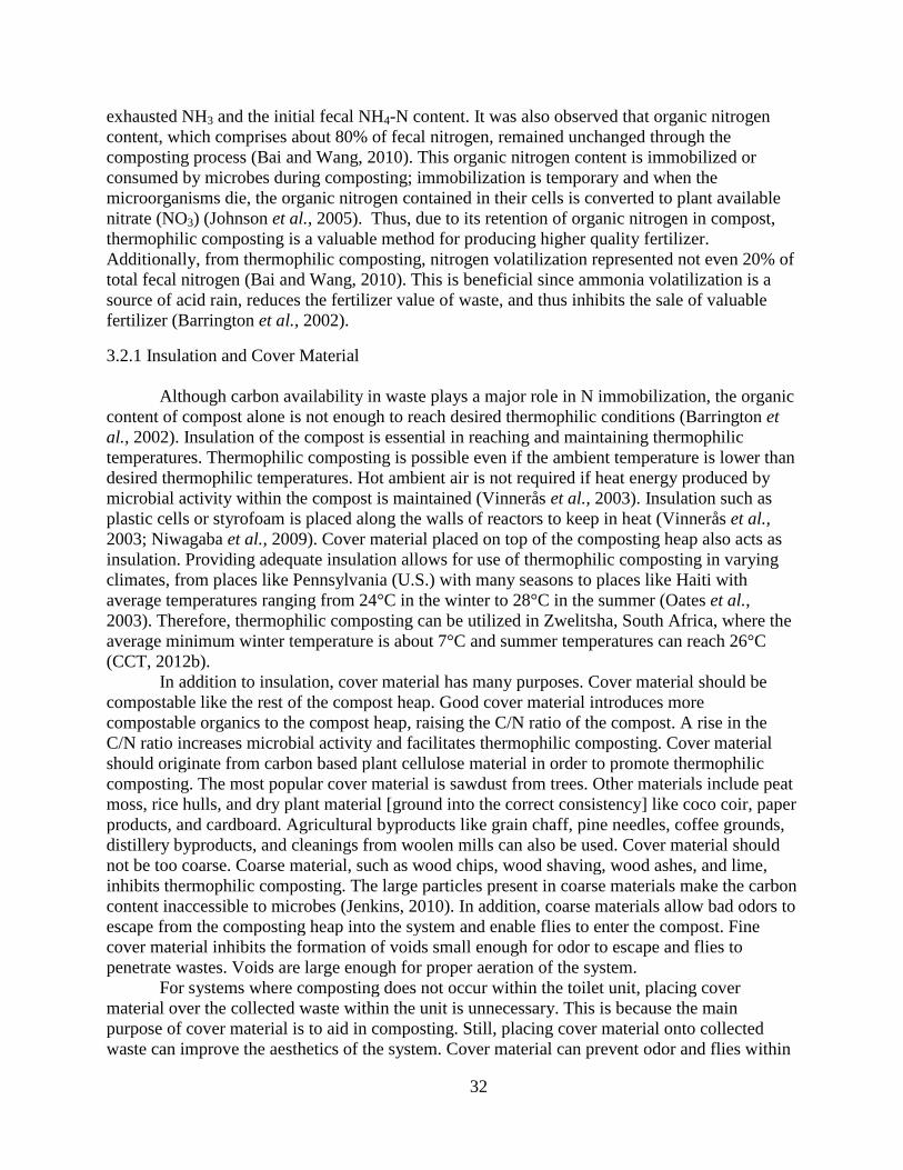
32
exhausted NH3 and the initial fecal NH4-N content. It was also observed that organic nitrogen
content, which comprises about 80% of fecal nitrogen, remained unchanged through the
composting process (Bai and Wang, 2010). This organic nitrogen content is immobilized or
consumed by microbes during composting; immobilization is temporary and when the
microorganisms die, the organic nitrogen contained in their cells is converted to plant available
nitrate (NO3) (Johnson et al., 2005). Thus, due to its retention of organic nitrogen in compost,
thermophilic composting is a valuable method for producing higher quality fertilizer.
Additionally, from thermophilic composting, nitrogen volatilization represented not even 20% of
total fecal nitrogen (Bai and Wang, 2010). This is beneficial since ammonia volatilization is a
source of acid rain, reduces the fertilizer value of waste, and thus inhibits the sale of valuable
fertilizer (Barrington et al., 2002).
3.2.1 Insulation and Cover Material
Although carbon availability in waste plays a major role in N immobilization, the organic
content of compost alone is not enough to reach desired thermophilic conditions (Barrington et
al., 2002). Insulation of the compost is essential in reaching and maintaining thermophilic
temperatures. Thermophilic composting is possible even if the ambient temperature is lower than
desired thermophilic temperatures. Hot ambient air is not required if heat energy produced by
microbial activity within the compost is maintained (Vinnerås et al., 2003). Insulation such as
plastic cells or styrofoam is placed along the walls of reactors to keep in heat (Vinnerås et al.,
2003; Niwagaba et al., 2009). Cover material placed on top of the composting heap also acts as
insulation. Providing adequate insulation allows for use of thermophilic composting in varying
climates, from places like Pennsylvania (U.S.) with many seasons to places like Haiti with
average temperatures ranging from 24°C in the winter to 28°C in the summer (Oates et al.,
2003). Therefore, thermophilic composting can be utilized in Zwelitsha, South Africa, where the
average minimum winter temperature is about 7°C and summer temperatures can reach 26°C
(CCT, 2012b).
In addition to insulation, cover material has many purposes. Cover material should be
compostable like the rest of the compost heap. Good cover material introduces more
compostable organics to the compost heap, raising the C/N ratio of the compost. A rise in the
C/N ratio increases microbial activity and facilitates thermophilic composting. Cover material
should originate from carbon based plant cellulose material in order to promote thermophilic
composting. The most popular cover material is sawdust from trees. Other materials include peat
moss, rice hulls, and dry plant material [ground into the correct consistency] like coco coir, paper
products, and cardboard. Agricultural byproducts like grain chaff, pine needles, coffee grounds,
distillery byproducts, and cleanings from woolen mills can also be used. Cover material should
not be too coarse. Coarse material, such as wood chips, wood shaving, wood ashes, and lime,
inhibits thermophilic composting. The large particles present in coarse materials make the carbon
content inaccessible to microbes (Jenkins, 2010). In addition, coarse materials allow bad odors to
escape from the composting heap into the system and enable flies to enter the compost. Fine
cover material inhibits the formation of voids small enough for odor to escape and flies to
penetrate wastes. Voids are large enough for proper aeration of the system.
For systems where composting does not occur within the toilet unit, placing cover
material over the collected waste within the unit is unnecessary. This is because the main
purpose of cover material is to aid in composting. Still, placing cover material onto collected
waste can improve the aesthetics of the system. Cover material can prevent odor and flies within

33
the toilet unit system. When source-separated feces are not composted within the toilet unit, they
are transferred to a separate reactor for composting. Within the reactor, cover material is crucial
for achieving thermophilic conditions. Cover materials used on compost piles can be coarser
than toilet cover materials. These include grasses, hay, straw, pine needles, weeds, leaves, and
other organic plant materials that are odor free and do not attract flies (Jenkins, 2010). A fresh
layer of cover material should be placed on top of the compost pile every time new waste is
added.
Composting reactors allow for the sanitation of larger volumes of feces and other organic
wastes than is possible within a single composting toilet unit. Additionally, they keep compost
away from children, animals or other vermin, or insects. A reactor should be constructed with a
“biological sponge” as its base layer. This layer consists of plant materials such as straw, hay,
weeds, and grass piled at the reactor’s base as an absorber of excess liquids that may collect
when wastes are placed within the reactor (Jenkins, 2010). Reactors can be placed on bare soil
with a slightly concave base. The concave base directs excess liquid to the center of the bin. This
prevents leaching from the side of the reactor bottom beyond the soil base perimeter. The benefit
of a soil base is that beneficial soil organisms, such as earthworms, can migrate into the compost
(Jenkins, 2010). Earthworms accelerate composting producing a premium organic soil
supplement called vermicompost (BioSystems, 2013c). Reactors can also be constructed on
concrete and other hard surfaces. It is important that sufficient material is used in the biological
sponge for liquid absorption. During thermophilic composting, excess liquid is rapidly
evaporated by the heat produced from microbial activity. Hence, to maintain compost moisture
content (optimal 45-60%), rainwater, greywater, and even urine may be used to moisten the mass
(Jenkins, 2010; Berger, 2011). With regards to reactor walls, many materials can be used,
including wood boards; masonry materials such as bricks, blocks or concrete; straw or hay bales
(which can be reused as cover material); bamboo; poles or logs; and wood shipping pallets
turned on their sides (Jenkins, 2010).
3.2.2. Proper Maintenance and Monitoring
Proper maintenance and monitoring are integral to safe and effective thermophilic
composting. Most importantly, maintenance personnel and operators of a fecal composting
system should remember the potentially high pathogen load that could be present in feces. As a
result, direct contact with fecal material should be avoided at all times. Precautionary measures
include wearing one-way rubber gloves and washing hands after handling wastes. Only mature
compost, which looks and smells like rich garden soil or leaf humus should be harvested for
reuse (Berger, 2011). All other material should remain in the compost reactor until it has been
sanitized. A standard procedure should be implemented to best ensure wastes compost
adequately.
The reactor must be prepped before wastes are transferred to the composting reactor from
composting toilets, kitchens, gardens, urine divergent systems. Before starting operation, a
biological sponge layer should be established at the reactor bottom. Next, on top of this layer,
cover material is placed (Berger, 2011). When wastes are ready to be added to the reactor, the
cover material should be wet, forming a moist bed for the added material. After the wastes are
added, fresh cover material should be evenly distributed across the top completely covering the
pile. This will sit until new waste needs to be introduced to the compost pile. The reactor must be
prepped before every new addition of waste. New wastes should never be added on top of an
existing compost pile. Instead they should be incorporated into the heap (Jenkins, 2010). Starting

34
from the heap’s epicenter, a composting tool, such as a pitch fork, can be used to pull away cover
material up and against each side wall of the reactor. As this happens, a depression in the top
center of the pile is formed. Into this depression is where the new material should be added. New
material is introduced to the middle of the heap since the center tends to be the hotter than the
areas closer to the reactor walls (Vinnerås et al., 2003). Proper insulation and periodic turning of
the waste material more evenly distributes the heat throughout the compost. In an active heap,
steam would be seen coming from the center upon digging the depression. Once the new wastes
are added, the cover material is pushed out from the walls redistributing evenly once again over
the compost top. Fresh cover material must be placed on top of the compost pile after every
introduction of new waste material. If properly performed, the heap should undergo thermophilic
composting within hours.
Once cover material is set and the pile is left to compost, certain monitoring techniques
can indicate to users if the system is functioning properly. The goal of thermophilic composting
is to reach thermophilic temperatures. Thus, users can monitor the temperature of the compost
using a 36 inch thermometer, which is directly placed into the compost. If temperatures are not
within the thermophilic range (40°C to 71°C) or if thermophilic temperatures are not maintained
for a long period of time (at least a week), then thermophilic conditions have not been met.
Another indicator of poor thermophilic conditions is bad odors originating from the compost
pile. Bad odors result from poor cover material selection such as coarse and/or inorganic material
that allow odors to escape the piles through large voids. Inadequate cover distribution is another
cause of bad odors. Flies collecting around the composting waste also demonstrate improper
system maintenance since they are attracted to the odor. If the proper cover material has been
selected and applied adequately, other important factors are not being met. Microbial activity can
greatly diminish if the wastes are not sufficiently aerated. The weight of more massive material
can cause compaction in the reactor. To ensure this is not the case, a user can take a pitchfork or
an aeration stick to mechanically move the organic material (Berger, 2011). Moisture contents
outside the optimum range can also inhibit decomposition. Adding greywater, rainwater, and/or
urine can remedy an overly dry compost. For wet composts, more material waste or cover
material should be added to soak up moisture. The pH of the compost can also inhibit activity.
Lime, soda ash, and/or algae flower are additives that can serve to raise the pH value if its falls
below 6.5 (Vinnerås, 2007; Berger, 2011). Still, too much ash additive decreases the organic
content of feces, presenting a less attractive environment for microorganisms in the compost
(Vinnerås, 2003). Therefore, regular maintenance and monitoring is crucial to achieving
maximum performance in a thermophilic composting system.

35
Chapter 4: Sanitation System Proposal
The vision of the CTPC is to have reliable sanitation on two levels: (1) the household
level and (2) the community level. The following sections propose sanitation systems on both
levels. As discussed in section 2.5.1, UDDT and composting toilet systems are the most
technically feasible and applicable for Zwelitsha. Neither system requires a sewer or water
connection. Each can be designed without energy dependent components or additional waste
disposal. Both systems have the capability of generating usable products, pose no safety
concerns if wastes are handled properly, and can be utilized in water-scarce areas like Zwelitsha.
4.1 Household Level Sanitation System
Sanitation systems within Zwelitsha currently take the form of communal toilet blocks.
Household systems are unprecedented (ISN et al., 2011). At night, communal toilet blocks
become sites for violence, rape, and overall crime (Kenney et al., 2011a). As a result, persons
fearing for their safety resort to alternate methods to satisfy their sanitation needs such as open
defecation and defecating in buckets. Thus, for an informal settlement resident whose safety is
threatened by satisfying his/her basic need of sanitation, a sanitation system within his/her own
home provides security.
Although urine diversion toilets harness the nutrient value of urine, the demand for urine
is less than that for fecal compost despite this nutrient advantage (Robinson, 2005).
Consequently, two options are presented for the household level toilet system: one for
households without a reuse application for urine and one for households with a reuse application
for urine. The first option is the Loveable Loo, a composting toilet developed by Joseph Jenkins,
author of “The Humanure Handbook – A Guide to Composting Human Manure” (Jenkins,
2005). The second option is a low cost UDDT designed for application in Africa by Peter
Morgan, Professor at the Stockholm Environment Institute in Stockholm, Sweden (Morgan,
2007). Each system can be built using minimal, inexpensive, and local materials and unskilled
labor.
4.1.1 The Loveable Loo
The Loveable Loo is a composting toilet, which collects fecal matter and urine in one
receptacle. It does not require water, electricity, venting, plumbing, or chemicals. This toilet
option is applicable in areas where urine reuse is unrealistic or lacking demand. The Loveable
Loo is a simple, economic, and sanitary option (Figure 10). This toilet system can be purchased
(retail price: $225) fully assembled and finished at the Humanure Store (Grove City, PA). It can
also be constructed by individuals using wood, a 5 gallon (20 L) bucket, a toilet seat and cover.

36
Figure 10. Loveable Loo (Humanure Store, 2013)
The humanure handbook website (Humanure Handbook, 2013) provides an 8-step visual
instruction for individuals wanting to construct their own Loveable Loo toilet system (see
Appendix A). The oveable oo toilet box is 18” wide and 21” long. Construction materials
include: two 3/4"x10"x18" boards and two 3/4"x10"x19.5" boards; two door hinges; one piece of
3/4"x18"x18" plywood and one piece of 3/4"x3"x18" plywood. These two pieces of plywood are
hinged together. The top of a 5 gallon bucket is used as a template to cut a hole in the larger
piece of plywood (3/4"x18"x18") to fit the top of the toilet receptacle. The hole must be only
1. ” back from the front edge of the plywood. It is important that toilet receptacles (buckets)
used in the system are all of identical size so they will fit properly within the toilet. The last
component is the toilet seat. A standard toilet seat should be purchased for the system. Zwelitsha
locals, CTPC members, or any other stakeholders of the household level sanitation system can
construct Loveable Loos easily and economically.
Loveable Loo toilets can be placed anywhere in the home. In addition to the toilet, an
area should be designated for holding cover material, preferably adjacent to the toilet. After each
use of the toilet system, cover material, such as saw dust from cut trees, must be put on top of the
human excreta within the toilet receptacle. This prevents odors and flies. If odors are coming
from the toilet, additional cover material should be added until the smell disappears. There
should also be multiple toilet receptacles (buckets) of identical size. A 20 L bucket fills up in
about a week when one adult is using the system (Humanure Handbook, 2013). This includes
fecal matter (feces and toilet paper), urine, and cover material (feminine products may also be
administered into the bucket). With multiple toilet receptacles, full buckets can be sealed, set
aside, and replaced by empty buckets. In this way, a household of 3 persons (around a typical
Zwelitsha household size) with six 20 L buckets can wait two weeks before needing to empty out
its buckets (CCT, 2012a).
For Zwelitsha, residents could either compost the waste on their property in compost bins
or transport the waste in the sealed buckets to the large scale WaSH facility mentioned in section
4.2. The CTPC aims to involve the community in the upgrading of WaSH services. Often, WaSH
facilities in informal settlements are not valued by residents and as a result are commonly
misused and/or vandalized (Kenney et al., 2011b). The CTPC has found that if spaces
simultaneously address needs such as unemployment, education, and communal space, residents
are more likely to value and care for them (Bell et al., 2010). Zwelitsha community members
have already expressed desires for foot pedal water taps, soap dispensers for water ablution
basins, trash and food bins, educational signs showing proper hygienic practices, laundry
wringers, and recreational space (Kenney et al., 2011a). The reuse potential of human excreta

37
can also have the potential of alleviating the financial burdens of unemployment for individuals.
Users of the Loveable Loo can be economically incentivized to transport their wastes to the
WaSH facility. Initially, before the sale of products returns profits to the facility, this economic
incentive can be subsidized by the CTPC or the municipality within the Stellenbosch-Langrug
partnership. This process can also incentivize other community members who are not currently
using Loveable Loos in their homes to begin using the systems. Strategies such as these can
work to involve all community members in the reuse of human excreta, which can promote the
use of sustainable toilet systems.
4.1.2 UDDT for African Context
The proposed UDDT is a low cost self-built toilet in which urine is collected in a plastic
container and the feces, together with soil and ash added to help the composting process, are
collected in a 20 litre bucket. If there is a realistic reuse application in Zwelitsha, at the
household level, the proposed low cost UDDT designed by Peter Morgan can be implemented.
The design developed by Morgan incorporates a concrete base slab, a vault built of fired bricks
and mortar, and a urine-diverting pedestal (Morgan, 2007). This UDDT can be constructed by
individuals using a 20 L bucket, cement, reinforcing wire, brick, mortar, a plastic pipe for urine-
diversion and a toilet seat and cover. Figures 11 through 14 show a constructed brick vault with
concrete and a complete toilet pedestal with urine pipe.
Figure 11. Front View of Vault with Toilet Slab Placed on Top (Morgan, 2007)
Figure 12. View from Behind Vault Showing Slanted Concrete Access Slab (Morgan, 2007)

38
Figure 13. View from Behind Vault Showing Removed Access Slab, 20 L Collection Bucket
within Vault, and Superstructure on Top Enclosing Toilet Pedestal for Privacy
(Morgan, 2007)
Figure 14. Toilet Pedestal with Urine-Diversion Pipe (Morgan, 2007)
Morgan (2007) provides detailed instruction on how to construction this UDDT system
(see Appendix B). The feces from the UDDT are used to make compost. Consequently, after
every use, individuals are recommended to add amendment (cover material) to the collection
bucket filled with deposited feces and toilet paper. Morgan (2007) recommends adding a mixture
of soil and wood ash. These materials should be premixed when they are dry at a ratio of four
parts soil to one part ash. About half a cup of this mix should be added following each
defecation. Other cover materials may also be used including ones mentioned in section 3.2.1.2.
It was observed that with the mixture of feces, toilet paper, soil, and wood ash, that the 20 L
bucket took between four and six weeks to fill up for a single user. This correlates to an average
daily waste production between a pound and a pound and a half.
The collection bucket containing the feces and waste mix is retrieved from behind the
UDDT system, as shown in Figure 13. From here, Morgan (2007) proposes that the feces mix be
to a secondary processing site. The toilet is considered the “primary processing site,” in that
compost ingredients are placed together and undergo initial decomposition. Still, fresh excreta
remain in the toilet system for a short period. Depending on how quickly the bucket fills up and
the number of users, it may take a few days or a week or two at most before the excreta are
transferred to the secondary processing site. This site can be a shallow pit composter (Figure 15)
or a split cement jar (Figure 16) near the UDDT system. A series of these is recommended for a
family or user groups of 5 or fewer. Once treated compost can be placed into cement basins from
which plants can directly grow. Morgan (2004a) provides instructions for constructing 10 L
cement basins and 30 L and 80 L split cement jars.

39
Figure 15. Emptying Bucket Contents into Shallow Pit Composter (Morgan, 2004b)
Figure 16. Three Cement Jars: One with an Painted Concrete Cover (left); One with
Standard Cement Lid (center); One with Plants Growing from it (right) (Morgan, 2004b)
For a family or user group of greater than 5, it is recommended to build a twin pit
composter (Figure 17) where the contents of the bucket are added to one shallow pit until it is
nearly full, then to a second shallow pit which fills whilst the contents of the first pit are
composting. Morgan (2004b) provides detailed information on the construction and use of twin
pit composter. In addition to the secondary processing sites proposed by Morgan (2007), the
large-scale WaSH facility containing a composting facility such as the one presented in section
4.2 can also serve as a site. Although ideal for onsite household reuse, Zwelitsha residents using
this UDDT can bring their buckets to the facility as an alternative or supplemental option if their
own systems are at capacity.
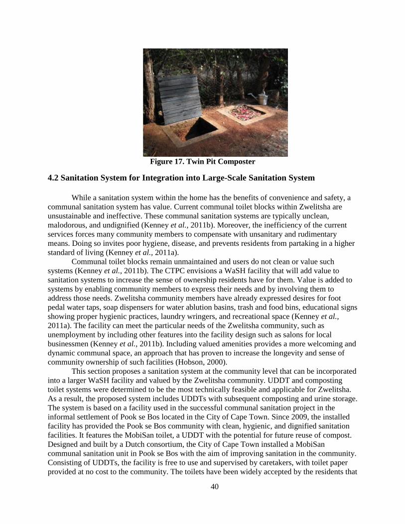
40
Figure 17. Twin Pit Composter
4.2 Sanitation System for Integration into Large-Scale Sanitation System
While a sanitation system within the home has the benefits of convenience and safety, a
communal sanitation system has value. Current communal toilet blocks within Zwelitsha are
unsustainable and ineffective. These communal sanitation systems are typically unclean,
malodorous, and undignified (Kenney et al., 2011b). Moreover, the inefficiency of the current
services forces many community members to compensate with unsanitary and rudimentary
means. Doing so invites poor hygiene, disease, and prevents residents from partaking in a higher
standard of living (Kenney et al., 2011a).
Communal toilet blocks remain unmaintained and users do not clean or value such
systems (Kenney et al., 2011b). The CTPC envisions a WaSH facility that will add value to
sanitation systems to increase the sense of ownership residents have for them. Value is added to
systems by enabling community members to express their needs and by involving them to
address those needs. Zwelitsha community members have already expressed desires for foot
pedal water taps, soap dispensers for water ablution basins, trash and food bins, educational signs
showing proper hygienic practices, laundry wringers, and recreational space (Kenney et al.,
2011a). The facility can meet the particular needs of the Zwelitsha community, such as
unemployment by including other features into the facility design such as salons for local
businessmen (Kenney et al., 2011b). Including valued amenities provides a more welcoming and
dynamic communal space, an approach that has proven to increase the longevity and sense of
community ownership of such facilities (Hobson, 2000).
This section proposes a sanitation system at the community level that can be incorporated
into a larger WaSH facility and valued by the Zwelitsha community. UDDT and composting
toilet systems were determined to be the most technically feasible and applicable for Zwelitsha.
As a result, the proposed system includes UDDTs with subsequent composting and urine storage.
The system is based on a facility used in the successful communal sanitation project in the
informal settlement of Pook se Bos located in the City of Cape Town. Since 2009, the installed
facility has provided the Pook se Bos community with clean, hygienic, and dignified sanitation
facilities. It features the MobiSan toilet, a UDDT with the potential for future reuse of compost.
Designed and built by a Dutch consortium, the City of Cape Town installed a MobiSan
communal sanitation unit in Pook se Bos with the aim of improving sanitation in the community.
Consisting of UDDTs, the facility is free to use and supervised by caretakers, with toilet paper
provided at no cost to the community. The toilets have been widely accepted by the residents that

41
recognise the improvement in the sanitation facilities and appreciate the privacy, cleanliness and
dignity offered by the unit (Quayle, 2012).
The MobiSan unit comprises 13 urine diverting communal toilets, in which urine is
separated from feces in individual chambers. Toilets stalls containing the toilets are raised up and
accessed via steps. This allows for the collection on the feces and urine below the toilets.
However, the toilets for children are only connected to the feces chamber, as it is considered too
difficult for children to use the urine diversion system correctly. The unit divides the toilets by
gender and age, providing seven toilets for women, three for men, and the remaining three for
children (Figure 18). Additionally, 12 waterless urinals for men are located on the back of the
unit (Figure 19). The facility serves 200 shacks of approximately 800 individuals (Quayle, 2012).
Figure 18. Toilet side of MobiSan: 13 UDDTs separated by gender and age (Quayle, 2012)
Figure 19. Urinal side of MobiSan: 12 waterless men’s urinals (Quayle, 2012)

42
While not essential for operation, the municipality provided the toilet block with
electricity for lighting to improve the safety for users and to power the ventilation, further
reducing the incidence of bad smells. A piped water supply was also provided for hand washing.
In addition, the municipality appointed local caretakers to supply cleaning materials and
toilet paper for residents and to ensure the unit was not vandalized or misused. The municipality
empties the feces chambers every six months and the urine tanks every 2 months. The feces and
urine are collected from within the toilet stalls in an area below the toilet. Until the reuse aspect
of the system is fully developed, the feces are disposed of via landfill and the urine at wastewater
treatment plants (Quayle, 2012).
Although modeled after the MobiSan project in Pook se Bos, the proposed system has
several keys differences. For one, the proposed system is not designed for the collection of feces
and urine by the municipality for removal offsite. Instead, it is designed for onsite treatment and
reuse of feces and urine. Secondly, the system is designed to serve a smaller population of 150
individuals or approximately one-fourth of the Zwelitsha population. Lastly, the proposed system
was designed with anticipation that electricity will not be provisioned by the municipality to
power the ventilation system. As a result, an air shaft was included in the design.
The main component of the proposed system is the UDDT unit, which will separate urine
and fecal matter. The CTPC wants to bring services to approximately 50 families. According to
Professor Scott Jiusto, Director of the CTPC at WPI, who has completed numerous projects in
Zwelitsha, a typical family or household is three individuals. Thus, the system is designed for a
user population of 150 persons. Given the Cape Town provision target of 1 toilet per 5
households, the system includes 10 toilets (CCT, 2012c). Each UDDT unit has a urine
compartment and a fecal matter shute (Figure 20). The two waste receptors are separated by a
dividing wall, which acts to prevent cross-contamination of urine and feces during and after
toilet use. Urine collected in the urine compartment flows toward a pipe inlet. As shown in
Figure 21, the inlet leads to a pipe that empties into a urine collection container. Urinals are also
included in the system where urine is directed via a pipe into a connected urine collection
container. The fecal matter, which includes feces, toilet paper, toilet paper center cardboard rolls
and feminine hygiene products, drops down the shute into a collection bin. A ventilation shaft is
located behind each toilet unit allowing air to pass through the unit, the fecal matter collection
area, and the outside. Throughout the system there are access flaps, enabling maintenance
personnel to retrieve the collected urine and fecal matter fractions for onsite processing. Figure
22 shows a rendered version of the whole system.

43
Figure 20. Schematic of UDDT Toilet Unit: Top View (Top Left); Angled Top View (Top
Right); Front View (Bottom Left); Side View (Bottom Middle); Side Cross-sectioned View
(Bottom Right)

44
Figure 21. Schematic of Facility Toilet System with Important Design Features
Figure 22. Rendered Version of Toilet System

45
Like the MobiSan project, the proposed system features a raised system in which steps
and a raised platform grant access to toilets on one side and urinals on the other. A modification
to the MobiSan design is a middle corridor in between the toilet units and urinals. The MobiSan
unit uses a double-vault (chamber) system with a mechanical device for mixing. Fecal matter is
collected in one chamber and is mixed manually via the mechanical device by the caretaker of
the system. When the first vault is full, its contents are transferred to the second chamber with
the help of the mixing device while the first one remains in use. In the second chamber, the fecal
matter is stored for further hygienisation and improvement of the end product quality (DWS,
2013). This corridor allows the caretaker of the system to retrieve the fecal matter waste fraction
from the toilet units and the urine waste fraction from the urinals for processing outside the units.
Additionally, the corridor removes the possibility of cross-contamination of feces and urine. This
is accomplished, specifically, because urine pipes never cross over fecal collection bins and there
are separating walls and individual compartments for each collection container. As seen in
Figure 22, the urine waste fraction from the toilet units are retrieved via an access flap within the
toilet stall directly in front of the toilet unit.
Retrieved waste may be treated onsite or offsite. Here, it is proposed that waste is treated
onsite. This eliminates the need for transport of waste offsite or for outside personnel to come
onsite and collect waste for treatment elsewhere. In the Pook se Bos MobiSan installation, the
municipality empties the feces chambers every six months and the urine tanks every two months.
Until the feces and urine from the system can be reused as agricultural products, the feces are
disposed of via landfill and the urine at wastewater treatment plants (Quayle, 2012). Within the
Stellenbosch-Zwelitsha partnership through SDI, wastes can be handled in the same way. Still,
here, the proposed system plans for treatment of wastes onsite.
The first element of the onsite waste treatment is the compost facility. Joseph Jenkins, a
compost practitioner in the United States since 1975, designed the compost facility proposed
here. With his expertise in composting, Jenkins has successfully grown food for his family from
humanure (human manure) compost for the last 30 years (Jenkins, 2010).
The compost facility has two compost storage bins, a storage area for cover material, and
a rainwater collection system (Figure 23). Compost storage bin volumes can vary. A typical
volume for a bin is 1 m3. Estimates of the expected fecal matter volume suggested that this
volume was adequate for the system. Since feces requires 6 months of treatment, estimates were
made for that period of time. The fecal matter volume was calculated considering the individual
contributions of feces, toilet paper and saw dust amendment to the system. In addition, it was
determined for a facility serving 150 individuals daily. Microsoft Excel was used to calculate the
daily fecal matter volume. From this, a final 6-month volume of approximately 1 m3 was
computed. Calculations were based on assumptions including daily fecal, toilet paper, and saw
dust mass production per person; feces, toilet paper and saw dust densities; individuals served
per day; the time fraction (or time spent by user at facility); and the percent decomposition of
waste over time. A chart showing the values along with associated assumptions is included in
Figure 24.

46
Figure 23. Schematic of Compost Facility: Rainwater Harvesting Side (left); Compost
Loading Side (right)

47
Figure 24. Fecal Matter Volume Calculation with Associated Assumptions

48
Thus, Figure 25 shows dimensions for one example of a storage bin. Similarly,
construction materials for the bins and the compost facility can vary. Wood, bricks, blocks or
concrete, straw or hay bales, bamboo, poles or logs, and wood shipping pallets are some of the
materials that can be used (Jenkins, 2010). The bins are used in parallel. Retrieved wastes are
placed into one compost bin at a time. When one bin is full, the bin is left to decompose without
introducing any additional wastes for at least a 6 month period. During this treatment period,
waste generated within the facility is emptied into the second compost bin. In between the two
bins is a storage area for cover material. Hay or straw stacks, grass, leaves, or any other organic
plant material can be stored here until it is placed onto the wastes within the adjacent compost
bins. A roof over the cover material storage area keeps the cover material dry by diverting
rainwater into gutters. Rainwater entering the gutters flows downward and collects in a collection
container. Barrels or plastic containers can be repurposed to serve as a collection container for
rainwater. The collected rainwater can be used to moisten the compost pile when thermophilic
composting dries up the pile to unfavorable conditions (urine can also be used.) Additionally, the
rainwater can be used to clean the urine and feces collection containers from the toilet system
after they are emptied into the compost bins. For this, the caretaker can use a cleaning tool, such
as a long-handled toilet brush, to scrub the containers with a mix of rainwater and biodegradable
non-antibacterial soap (antibacterial soaps or substances should not be used at any point within
the system since they can kill off bacteria necessary for thermophilic composting). About 1
gallon of water can clean two 5 gallon containers. The resulting rinse water should be added
directly into the compost. This moistens the drying compost, eliminates the need for alternative
disposable options, and prevents unsustainable introduction of wastewater into the environment.
Figures 26 and 27 show rendered versions of the compost facility.

49
Figure 25. Aerial View (top), Front View (bottom left), and Side View (bottom right) for
Compost Facility

50
Figure 26. Composting Facility on Concrete Slab (Compost Loading Side)
Figure 27. Compost Facility on Soil (Rainwater Harvesting Side)
The second element of the onsite waste treatment is the urine storage tanks. Storage tanks
can be constructed of glass fiber reinforced plastic, PE, polypropylene (PP), PVC, rubber
bladders, high-quality reinforced concrete, or stainless steel. Plastic tanks which are sold for
rainwater harvesting are also suitable as urine storage tanks, and can be a good low-cost solution
in developing places like Zwelitsha (Münch and Winker, 2011). Storage tanks should be
completely watertight to avoid loss of urine, prevent groundwater contamination (for systems
placed directly onto ground with no liner), and prevent groundwater from entering the tank from
the outside. As shown in Figure 28, a concrete foundation can be placed below the tanks to serve
as a barrier to any urine leakage. Plastics liners are also an option. Like the compost bins, storage
tanks are used in parallel. Retrieved wastes are place into one storage tank at a time. When one

51
tank is full, the tank is left without introducing any additional urine for at least a 30 day period.
During this treatment period, urine generated within the facility is emptied into the second
storage tank.
Figure 28. Schematic of Urine Storage Tank with Important Design Features: Aerial View
(top); Side View (bottom)
The caretaker can add collected urine to the tank by climbing the access staircase and
opening the access door located on top of the tank. Once urine is ready for reuse it can be
retrieved via the urine outlet located on the end of the tank. Since the tank sits raised up on top of
supports, gravity directs urine to the outlet for removal. The proposed storage tank volume is 5
m3. Figures 29 and 30 show rendered versions of the urine storage tanks.

52
Figure 29. Urine Storage Tank with Access Lid Open
Figure 30. Urine Storage Tank with Closed Access Lid
The proposed urine storage tank volume (5 m3) is based on the estimated 30-day storage
capacity for a facility with toilets serving 150 individuals daily. This volume was calculated
using Microsoft Excel. Calculations were based on assumptions including daily urine volume,
families to be provisioned, families per toilet, household size, number of toilets needed,
individuals served per day, and the time fraction (or time spent by user at facility). A chart
showing the values along with associated assumptions is included in Figure 31.

53
Figure 31. Urine Volume Calculations with Associated Assumptions

54
Altogether, the large-scale community level facility has toilets and urinals for Zwelitsha
resident use and onsite treatment of human excreta with a compost facility and urine storage
tanks. Rendered versions of the facility are displayed in Figures 32 and 33. Depending on
available materials and user demand, the design of this facility can vary. Still, the proposal herein
is for a facility containing three main components: (1) a sanitation system (toilets and urinals),
(2) onsite composting, and (3) onsite urine storage. The combination of these three features
eliminates the need for waste collection for disposal offsite by outside personnel. Additionally, it
presents the opportunity for immediate reuse applications onsite if agriculture is practiced at the
WaSH facility incorporating the proposed system.
Figure 32. Toilet Facility (middle) with Parallel Urine Storage Tanks (left) and Composting
Station (right)
Figure 33. View of Composting Station and Toilet Facility looking into Toilet Stalls

55
Chapter 5: Conclusions and Recommendations
5.1 Conclusions
Globally, water, sanitation, and hygiene (WaSH) issues affect over 3 billion people.
Currently, 605 million people lack access to safe drinking water and 2.5 billion people lack
access to basic sanitation. Often, this lack of access is a daily realty for persons residing in
informal settlements throughout the developing world. The focus of this thesis was the area
called Zwelitsha in the informal settlement of Langrug. Located in Stellenbosch Municipality
near Cape Town, South Africa, Zwelitsha currently has one working drinking water tap and few
functional toilets for its 604 residents. The aim of this thesis was to address the shortcomings in
the provision of sanitation services within Zwelitsha. Thus, the major objectives of this thesis
were: (1) to evaluate possible sanitation systems and (2) to select a sustainable and technically
feasible toilet system to meet the sanitation needs of Zwelitsha as part of a WaSH facility.
Of the systems reviewed, urine diversion dehydration toilet and composting toilet
systems were determined to be the most technically feasible and sustainable sanitation options
for the informal settlement. Neither of the proposed systems require a water or sewage
connection or electricity. Additionally, these systems can eliminate wastes through their potential
reuse applications: urine as a sterile fertilizer and feces as a soil conditioner and fertilizer.
At the household level, two alternatives are the Loveable Loo and the Morgan UDDT.
The Loveable Loo consists of a 5 gallon (20 L) bucket system in a constructed toilet housing to
which cover amendment is added after use. Using the Loveable Loo, a family of 3 would need 3
buckets per week to meet their sanitation needs. The Morgan UDDT incorporates a concrete base
slab, a brick vault, and a urine-diverting pedestal. It can be constructed using a 5 gallon (20 L)
bucket, cement, reinforcing wire, brick, mortar, a plastic pipe for urine-diversion and a toilet seat
and cover. Using the Morgan UDDT, a single user may take between four and six weeks to fill
the bucket.
On the communal level, a UDDT system with subsequent onsite urine storage and
thermophilic composting was proposed for the settlement. The proposed system was designed to
serve 150 Zwelitsha residents daily with 10 toilets and 5 urinals. The composting stations for
onsite fecal compost treatment were designed with a volume of 1 m3
to accommodate fecal
matter over a 6 month treatment period. The urine storage tank for onsite urine treatment was
designed with a volume of 5 m3 to allow for a 30-day treatment period. Once treated, it was
proposed that the fecal compost and urine be reused as agricultural products onsite.
5.2 Recommendations for Future Work
The implementation of sanitation systems will take great consideration and other factors
will contribute to project success or failure. With respect to the proposed systems, the following
sections offer recommendations for future work toward a successful project.

56
5.2.1 Integrate Sanitation into a Full-Service WaSH Facility
The primary ways to reduce the transmission of enteric pathogens are through safe stool
disposal and adequate handwashing. Therefore, it is recommended that toilet systems be
integrated into a multi-service WaSH facility with handwashing stations and a supply of clean
water and soap. Among WaSH issues, providing adequate facilities to dispose of bodily
excretions and promoting the hygienic practice of washing hands with soap may be almost three
times as effective as improving water quality, reducing the risk of diarrhea by 47% (Curtis and
Cairncross, 2003). Consequently, the facility should promote the hygienic practice of washing
hands with soap and associated education programs should be implemented in the community.
5.2.2 Cultivate User Awareness
Cultivating user awareness of proper system use is recommended to maximize the
effectiveness and success of UDDT and composting toilet systems. The recommendations
include:
Employ a Caretaker: A WaSH caretaker can supervise individuals using the system, clean
toilet units, distribute soap and toilet paper, handle wastes, and discourage vandalism of
the system. The presence of a caretaker can help raise awareness on proper use of
sanitation systems.
Stress Importance of Cleaning System Regularly: Regular cleaning of the toilet and toilet
areas is an important method of maintaining the sanitation systems. Biological
disinfectants such as a vinegar or citric acid are recommended for cleaning the toilets as
these will not inhibit proper treatment. Chemical disinfectants should be used on surfaces
that are touched by users within communal toilet systems since hands are vectors for
disease transmission.
Involve Users in Reuse Activities: User awareness can be increased by involving users in
the reuse of excreta, for example, via farming on an onsite garden. Users can see first-
hand the value of excreta separation through the local production of food and/or growing
food for their families on the household level. Furthermore, an external demand for
agricultural products generated from human excreta can enable individuals to earn profit
from product sale.
5.2.3 Enlist Local Farmers in Excreta Reuse
Local farmers are crucial stakeholders for any system that generates agricultural products
from human excreta. Engaging farmers early can provide valuable agricultural expertise about
desired fertilizer for the specific crops of the local region. Furthermore, they represent the
potential demand for the products since they comprise the target market. Several concerns
surrounding sustainable sanitation systems with excreta reuse are generating products above
agricultural demand, quality control and safety, and product acceptability by farmers and by
persons consuming the crops of farmers who use the products (Kvarnström et al., 2006; Richert
et al., 2010). A few recommendations for further research into these concerns are:
Research Options for Handling Excreta Surplus: One potential option is contracting
farmers who can regularly pickup treated excreta for immediate use or untreated excreta

57
for treatment on their own land. Contracting farmers who have knowledge of excreta
reuse is recommended. Regardless of farmer knowledge, proper contracts regulating
storage length, quality control, application methods, and so on should be arranged
(Kvarnström et al., 2006).
Assess Compliance with EHS: In general, system managers should be able to assess
compliance with environmental health and safety (EHS) standards at all phases of system
operation and reuse.
Assess Local Acceptance of Human Excreta Reuse in Agriculture: Due to varied levels of
acceptance and differing attitudes towards the reuse of human excreta in agriculture, local
reception should be investigated.
5.2.4 Perform a Financial and Economic Analysis of System
Prior to system investment, it is recommended to perform a financial and economic
analysis. A full financial analysis includes all expenditures and revenue streams associated with a
system. To ensure system sustainability, the recurring costs for operation and maintenance and
not just initial investment costs should be considered. As a potential revenue stream for resource-
separating systems, excreta reuse should be included in a long-term financial cost-benefit
analysis. An economic analysis including financial costing as its core and the assignment of
monetary values to social and environmental costs and benefits should also be conducted
(Parkinson et al., 2012).

58
References
Aqua-Calc (Aqua-Calc). 2013. Densities for common substances and materials, foods and
gravels: Average density at standard atmospheric conditions.
http://www.aqua-calc.com/page/density-table/substance/ (accessed May 2013)
Bai and Wang (Bai, F. and Wang, X.). 2010. Nitrogen-retaining property of compost in an
aerobic thermophilic composting reactor for the sanitary disposal of human feces. Front.
Environ. Sci. Engin. China. [Online] 2010, 4 (2), 228-234.
Barnstable (Barnstable County Department of Health). 2013. Incinerating Toilets.
http://www.barnstablecountyhealth.org/ia-systems/information-center/
compendium-of-information-on-alternative-onsite-septic-system-technology/
incinerating-toilets (accessed May 2013)
Barrington et al. (Barrington, S., Choinière, D., Trigui, M., & Knight, W.). 2002. Effect of
carbon source on compost nitrogen and carbon losses. Biores. Tech. 2002, 83 (3), 189-
194.
Bell, H., Barbour, I., Gottshall, A., & Sparrell, C. (2010). Supporting early childhood
development in Monwabisi Park. Worcester Polytechnic Institute: Worcester, MA, 2010;
1-5.
Berger (Berger, Wolfgang). 2011. Technology review of composting toilets: Basic overview of
composting toilets (with or without urine diversion). GIZ. Eschborn, Germany, [Online]
2011; 1-21.
BioSystems (BioSystems Solutions). 2013a. Composting Methods.
http://www.biosystemsolutions.com/learn/composting_methods.html
(accessed May 2013)
BioSystems (BioSystems Solutions). 2013b. Thermophilic Composting.
http://www.biosystemsolutions.com/learn/thermophilic_composting.html
(accessed May 2013)
BioSystems (BioSystems Solutions). 2013c. Vermi-Composting.
http://www.biosystemsolutions.com/learn/vermi_composting.html (accessed May 2013)
BLS (United States Bureau of Labor Statistics). 2013. Consumer Price Index Inflation
Calculator. http://www.bls.gov/data/inflation_calculator.htm (accessed May 2013)
Brooks et al. (Brooks, S., Dempsey, M., Erlandson, T., MacDonald, C., Nichols, B., Reif M.,
Rookey, R., Venegas, J.). 2012. Laying the Foundation for a Resilient Partnership:
Innovative Upgrading in the Informal Settlement of Langrug. Worcester Polytechnic
Institute: Worcester, MA, 2011; 1-8.

59
Carr-Hill (Carr-Hill, R.). 2013. Missing millions and measuring development progress. World
Dev. Institute of Education, London, United Kingdom, [Online] 2013, 46(0), 30-44.
CCT (City of Cape Town). 2012a. 2011 Census. City of Cape Town, Strategic Development
Information and GIS Department. Cape Town, South Africa, [Online] 2012; 1-5.
CCT (City of Cape Town). 2012b. Water Services Development Plan 2012/2013: Demographics.
City of Cape Town, Water and Sanitation Department. Cape Town, South Africa,
[Online] 2012; 15-37.
CCT (City of Cape Town). 2012c. Water Services Development Plan 2012/2013: Service Levels.
City of Cape Town, Water and Sanitation Department. Cape Town, South Africa,
[Online] 2012; 38-48.
Chanyasak and Kubota (Chanyasak, V. and Kubota, H.). 1981. Carbon/organic nitrogen ratio in
water extract as measure of composting degradation. J. Ferment. Technol. 1981, 59 (3);
215–219.
Curtis and Cairncross (Curtis, V., & Cairncross, S.). 2003. Effect of washing hands with soap on
diarrhoea risk in the community: A systematic review. The Lancet Infect. Dis. [Online]
2003, 3 (5), 275-281.
DWS (Dutch Water Sector). 2013. Landustries places second generation MobiSan dry sanitation
unit in Cape Town. http://www.dutchwatersector.com/news-events/news/
631-landustries-places-second-generation-mobisan-dry-sanitation-unit-in-cape-town.html
(accessed May 2013)
ECSECC (Eastern Cape Socio Economic Consultative Council). 2012. Census 2011- Key
Results for the Eastern Cape. Vincent, East London, [Online] 2012; 1-6.
Engel et al. (Engel, A., Kunz, A., and Blanke, M.). 2001. Effects of compost and wood chippings
on soil nutrients and on vegetative and reproductive growth and fruit quality of apple to
overcome the replant problem. Erwerbsobstbau 2001, 43 (6), 153–160.
EPA (U.S. Environmental Protection Agency, Office of Water). 2000. Water Efficiency
Technology Fact Sheet: Oil Recirculating Toilets. NSCEP: Washington, D.C., [Online]
2000; 1-4.
Fabrega (Fabrega, D.C.). 2007. Decision Support Tool for the Appropriate Selection of
Sanitation Systems. Wageningen University, Department of Environmental Sciences, The
Netherlands, [Online] 2007; 1-94.
FAO (Food and Agriculture Organization of the United Nations, Land and Plant Nutrition
Management Service Land and Water Development Division). 2005. Fertilizer use by
crop in South Africa. Rome, Italy, [Online] 2005; 1-38.

60
Feachem et al. (Feachem, R.D., Bradley, D.J., Garelick, H., and Mara, D.D.). 1983. Sanitation
and Disease: Health Aspects of Excreta and Wastewater Management. World Bank
Studies in Water Supply and Sanitation 3. John Wiley & Sons: Washington, D.C., 1983;
1-68.
Franceys et al. (Franceys R., Pickford J., and Reed R.). 1992. A guide to the development of on-
site sanitation. World Health Organization, Geneva, Switzerland, 2002.
Gensch et al. (Gensch, Robert, Miso, Analiza, and Itchon, Gina). 2011. Urine as Liquid Fertilizer
in Agricultural Production in the Phillippines: A Practical Field Guide. Xavier University
Press: Cagayan de Oro, Philippines, [Online] 2011; 1-42.
HDA (The Housing Development Agency). 2012. Western Cape: Informal Settlements Status.
Johannesburg, South Africa, [Online] 2012; 1-38.
Heinonen-Tanski and van Wiik-Sijbesma (Heinonen-Tanski, H. and van Wijk-Sijbesma, C.).
2005. Human excreta for plant production. Bioresource Technology, 2005, 96 (4), 403-
411.
Henis, 1986 (Henis, Y.). 1986. Soil microorganism, soil organic matter and soil fertility
Chen, Y., Avnimelech, Y., Eds.; Developments in Plant and Soil Sciences: The Role of
Organic Matter in Modern Agriculture; Springer Netherlands: The Netherlands, 1986; 25,
159-168.
Hobson (Hobson, J.). 2000. Sustainable sanitation: experiences in Pune with a municipal-NGO
community partnership. Environ. and Urbaniz. 2000, 12 (2); 53-62.
Hoffmann et al. (Hoffmann, Heike, Platzer, Christoph, Winker, Martina, and Münch, E.v.).
2011. Technology review of constructed wetlands: Subsurface flow constructed wetlands
for greywater and domestic wastewater treatment. SuSanA. Esborn, Germany, [Online]
2011; 1-36.
Höglund (Höglund C.). 2001. Evaluation of microbial health risks associated with the reuse of
source-separated human urine. Bioteknologi: Royal Institute of Technology, Department
of Biotechnology, Stockholm, Sweden, 2001; 1-78.
Huag (Haug, R.T.) 1993. The Practical Handbook of Compost Engineering. LEWIS: Boca
Raton, FL, USA 1993; 1-699.
Humanure Handbook (Humanure Handbook). 2013. Make your own Humanure Toilet.
http://humanurehandbook.com/humanure_toilet.html (accessed May 2013)
IIUD (Institute for International Urban Development). 2013. Re-Blocking: In-situ Upgrading of
Informal Settlements in South Africa.
http://i2ud.org/2013/02/
re-blocking-in-situ-upgrading-of-informal-settlements-in-south-africa/

61
(accessed May 2013).
ISN et al. (Informal Settlement Network, Stellenbosch Municipality, Langrug Community
Leadership, and Community Organisation Resource Centre). 2011. Langrug Settlement
Enumeration Report. Franschhoek; Stellenbosch Municipality, South Africa, [Online]
2011; 1-21.
Jenkins (Jenkins, J.). 2005. The Humanure Handbook: A Guide to Composting Human Manure,
3; Joseph Pub.: Grove City, PA, USA, 2010; 1-255.
Jenkins (Jenkins, J.). 2010. Humanure Sanitation: The “no waste, no pollution, nothing to
dispose of” toilet system. Joseph Pub.: Grove City, PA, USA, [Online] 2010; 1-18.
Johnson et al. (Johnson, C., Albrecht, G., Ketterings, Q., Beckman, J., and Stockin, K.). 2005.
Nitrogen Basics – The Nitrogen Cycle. Agronomy Fact Sheet Series. Cornell University
Cooperative Extension: Department of Crop and Soil Sciences, College of Agriculture
and Life Sciences, Cornell University, Ithaca, NY, [Online] 2005; 1-2.
Jönsson et al. (Jönsson, H., Vinnerås, B., Höglund, C., Stenström, T. A., Dalhammar, G., and
Kirchmann, H.). 2000. Recycling source separated human urine. VA-forsk report, 1.,
2000.
Jönsson and Vinnerås (Jönsson, H. and Vinnerås, B.). 2004. Adapting the nutrient content of
urine and faeces in different countries using FAO and Swedish data. In: Ecosan –Closing
the loop. Proceedings of the 2nd international symposium on ecological sanitation,
incorporating the 1st IWA specialist group conference on sustainable sanitation. Lübeck,
Germany, 7th-11th April 2003; GTZ: Eschborn, Germany, 2004; 623-626.
Jönsson et al. (Jönsson, H., Richert Stintzing, A., Vinnerås, B. and Salomon, E.). 2004.
Guidelines on the use of urine and faeces in crop production. Report 2004-2. EcoSanRes
Publications Series; EcosSanRes Programme and Stockholm Environment Institute:
Stockholm, Sweden, [Online] 2004; 1-36.
Kalbermatten et al. (Kalbermatten, J.M., Julius, D.S., and Gunnerson, C.G.). 1982. Appropriate
sanitation alternatives: a technical and economic appraisal; John Hopkins University Press:
Baltimore, MD, USA, 1982; 1-115.
Kenney et al. (Kenney, M., Sheppard, P., Shooshan, R., and Siemian, J.). 2011a. WaSHUp:
Innovating water sanitation and hygiene upgrading in Langrug – Process Guide.
Worcester Polytechnic Institute: Worcester, MA, 2011; 1-42.
Kenney et al. (Kenney, M., Sheppard, P., Shooshan, R., and Siemian, J.). 2011b. Innovating
water sanitation and hygiene upgrading in Langrug – Executive Summary. Worcester
Polytechnic Institute: Worcester, MA, 2011; 1-5.

62
Kirchmann and Pettersson (Kirchmann, H. and Pettersson, S.). 1995. Human urine Chemical
composition and fertiliser use efficiency. Fert. Res. 1995, 40, 149-154.
Kvarnström et al. (Kvarnström, Elisabeth, Emilsson, Karin, Stintzing, A. R., Johansson, Mats,
Jönsson, Håkan, Petersens, E. a., Schönning, Caroline, Christensen, Jonas, Hellström,
Daniel, Qvarnström, Lennart, Ridderstolpe, Peter, and Drangert, Jan-Olof). 2006. Urine
Diversion: One Step Towards Sustainable Sanitation. EcoSanRes. SEI. Stockholm,
Sweden, [Online] 2006; 1-66.
Lin et al. (Lin, S., Shih, S., Wu, D., Lee, Y., Wu, C., Lo, L., and Shiea, J.). 2007. Matrix-assisted
laser desorption/ionization time-of-flight mass spectrometry for the detection of
hemoglobins as the protein biomarkers for fecal occult blood. Rapid Comm. Mass
Spectrom. [Online] 2007, 21 (20); 3311-3316.
Loetscher (Loetscher T., Keller J). 2002. A decision support system for selecting sanitation
systems in developing countries. Advanced Wastewater Management Centre, The
University of Queensland, Brisbane, Australia, Socio-Economic Planning Sciences. 2002,
36, 267–290.
Maurer et al. (Maurer, M., Pronk, W. and Larsen, T. A.). 2006. Treatment processes for source-
separated urine. Water Research 2006, 40 (17), 3151-3166.
Maurer (Maurer, M.). 2007. Urine treatment – absolute flexibility, Eawag News, results from
Novaquatis research project, Dübendorf, Switzerland, [Online] 2007.
Mnkeni and Austin (Mnkeni, P.N.S and Austin, L.M.). 2009. Water S.A. 2009, 35 (1), 133
Morgan (Morgan, Peter). 2004a. Some Special Constructional Techniques. In An Ecological
Approach to Sanitation in Africa: A Compilation of Experiences. EcoSanRes, Stockholm:
Stockholm, Sweden, 2004; 1-23.
Morgan (Morgan, Peter). 2004b. Urine Diversion-how to build and manage a single vault
composting toilet system. In An Ecological Approach to Sanitation in Africa: A
Compilation of Experiences. EcoSanRes, Stockholm: Stockholm, Sweden, 2004; 11-12.
Morgan (Morgan, Peter). 2007. Toilets That Make Compost: Low-cost, sanitary toilets that
produce valuable compost for crops in an African context. EcoSanRes: Stockholm
Environment Institute, Stockholm, Sweden, 2007; 1-100.
Münch and Winker (Münch, E.v. and Winker, Martina). 2011. Technology review of urine
diversion components: Overview of urine diversion components such as waterless
urinals, urine diversion toilets, urine storage and reuse systems. SuSanA. Esborn,
Germany, [Online] 2011; 1-32.

63
Navarro (Navarro R.G.). 1994. Improving Sanitation in Coastal Communities with Special
Reference to Puerto Princesa, Palawan Province, Philippines. School of Architecture,
McGill University: Montreal, Canada, [Online] 1994; 1-123.
Niwagaba et al. (Niwagaba, C., Nalubega, M., Vinnerås, B., Sundberg, C., & Jönsson, H.). 2009.
Bench-scale composting of source-separated human faeces for sanitation. Waste
Management 2009, 29 (2), 585-589.
NSFC. (National Small Flows Clearinghouse). 2000. Alternative Toilets: Options for
Conservation and Specific Site Conditions. Pipeline. [Online] 2000, 11 (3), 1-10
Oates et al. (Oates, P. M., Shanahan, P., & Polz, M. F.). 2003. Solar disinfection (SODIS):
Simulation of solar radiation for global assessment and application for point-of-use water
treatment in Haiti. Water Res. [Online] 2003, 37(1), 47-54.
Parkinson et al. (Parkinson, Jonathan, Hutton, Guy, Pfeiffer, Verena, Blume, Steffen, and
Feiereisen, Philipp). 2012. Sustainable Sanitation Alliance Factsheet: Financial and
economic analysis. SuSanA. [Online] 2012; 1-8.
Quayle (Quayle, T.). 2012. MobiSan: Communal urine diversion toilets in Pook se Bos, Cape
Town. ACCESSanitation, [Online] 2012; 1-6.
Richert et al. (Richert, A., Gensch, R., Joensson, H., Stenstroem, T., and Dagerskog, L.). 2010.
Practical Guidance on the Use of Urine in Crop Production: EcoSanRes Programme
Stockholm Environment Institute Kräftriket 2B, Stockholm, Sweden, [Online] 2010; 1-
55.
Robinson, Brian, E. (2005). Household Adoption of Ecological Sanitation:
An Assessment of Agricultural Value and User Perspectives in Nyanza Province, Kenya.
Massachusetts Institute of Technology: Massachusetts, USA, [Online] 2005; 1-154.
Rodriques et al. (Rodriques, Elvira, Gie, Janet, and Craig Haskins). 2006. Informal Dwelling
Count for Cape Town (1993-2005). City of Cape Town, Information and Knowledge
Management Department, Strategic Information Brach. Cape Town, South Africa,
[Online] 2006; 1-15.
Saito et al. (Saito, T., Hayakawa, T., Nakamura, K., Takita, T., Suzuki, K., and Innami, S.).
1990. Fecal Output, Gastrointestinal Transit Time, Frequency of Evacuation and
Apparent Excretion Rate of Dietary Fiber in Young Men Given Diets Containing
Different Levels of Dietary Fiber. J. Nutr. Sci. Vitaminol. 1990, 37, 493-508.
Schönning (Schönning, Caroline). 2001. Urine Diversion-hygienic risks and microbial guidelines
for reuse. Department of Parasitology, Mycology and Environmental Microbiology
Swedish Institute for Infectious Disease Control (SMI). Stockholm, Sweden, [Online]
2001; 1-41.

64
SDI (South African SDI Alliance). 2013. Informal Settlement Upgrading: Langrug.
http://sasdialliance.org.za/projects/langrug/ (accessed May 2013)
Smith et al. (Smith, D.C., Beharee, V., Hughes, J.C.). 2001. The effects of composts produced by
a simple composting procedure on the yields of Swiss chard (Beta vulgaris L.
var. flavescens) and common bean (Phaseolis vulgaris L. var. nanus). Scientia
Horticulture 2001, 91 (3-4), 393-406.
StatsSA (Statistics South Africa). 2011. Census 2011: Census in brief. Pretoria, South Africa,
[Online] 2011; 1-102.
Stoner (Stoner, C. H.). 1977. Goodbye to the Flush Toilet: Water-Saving Alternatives to
Cesspools, Septic Tanks, and Sewers. Rodale Press: Emmaus, Pennsylvania, [Online]
1977; 1-286.
Storburn (Storburn International Inc.). 2013. Info-Specifications-Operation: Storburn 60K Series
Pollution-Free Toilets. http://www.storburn.ca/storburn.html (accessed May 2013)
Udert et al. (Udert, K., Larsen, T., Biebow, M., and Gujer, W.). 2003. Urea hydrolysis and
precipitation dynamics in a urine-collecting system. Water Research [Online] 2003, 37
(11) 2571-2582.
Udert et al. (Udert, K., Larsen, T., Biebow, M., and Gujer, W.). 2006. Fate of major compounds
in source-separated urine. Water Science and Technology 2006, 54 (11-12), 413-420.
UN (United Nations). 2012. The Millennium Development Goals Report. New York, USA,
[Online] 2012; 1-68.
UN (United Nations). 2013. United Nations Millennium Development Goals.
http://www.un.org/millenniumgoals/ (accessed May 2013)
UNICEF (United Nations Children’s Emergency Fund). 2013. Water, Sanitation and Hygiene.
UN. http://www.unicef.org/wash/ (accessed May 2013)
USDA (United States Department of Agriculture, Forest Service Equipment Development
Center). 1975. Oil-Recirculating Waterless Toilet. San Dimas, California. [Online] 1975;
1-6.
Vandenberg (Vandenberg, Samantha). 2013. "SDI Agreement 'first in the world'" Eikestad Nuus.
http://eikestadnuus.mobi/news/read/1193/sdi-agreement-first-in-the-world
(accessed May 2013)
Vinnerås (Vinnerås, B., Björklund, A., and Jönsson, H.). 2003. Thermal composting of faecal
matter as treatment and possible disinfection method––laboratory-scale and pilot-scale
studies. Bioresource Technology 2003, 88 (1), 47-54.

65
Vinnerås et al. (Vinnerås, B., Palmquist, H., Balmer, P. and Jönsson, H.). 2006. The
characteristics of household wastewater and biodegradable solid waste – A proposal for
new Swedish design values. Urban Water [Online] 2006, 3 (1), 3-11.
Vinnerås (Vinnerås, B.). 2007. Comparison of composting, storage and urea treatment for
sanitising of faecal matter and manure. Bioresource Technology, [Online] 2007, 98 (17),
3317-3321
Vinnerås et al. (Vinnerås, B., Nordin, A., Niwagaba, C., and Nyberg, K.). 2008. Inactivation of
bacteria and viruses in human urine depending on temperature and dilution rate. Water
Research, [Online] 2008, 42 (15), 4067-4074.
WHO (World Health Organization). 1999. Environmental Health Indicators: Framework and
Methodologies- Protection of the Human Environment, Occupational and Environmental
Health Series. Geneva, Switzerland, [Online] 1999; 1-119.
WHO (World Health Organization). 2006. WHO Guidelines for the Safe Use of Wastewater,
Excreta and Greywater: Excreta and greywater use in agriculture. Geneva, Switzerland.
2006; Vol. 4.
WHO (World Health Organization). 2013a. Water Sanitation and Health (WSH): Health through
safe drinking and basic sanitation. http://www.who.int/water_sanitation_health/mdg1/en/
(accessed May 2013)
WHO (World Health Organization). 2013b. Water Supply, Sanitation and Hygiene
Development. http://www.who.int/water_sanitation_health/hygiene/en/
(accessed May 2013)
WRC (Water Research Commission). 2007. Sanitation Decision Support Model. Pretoria. South
Africa
WSCC (Water Supply & Sanitation: Collaborative Council). 2013. Global WaSH Campaign.
http://www.wsscc.org/wash-advocacy/campaigns-events/global-wash-campaign
(accessed May 2013)

66
Appendix A: Constructing a Loveable Loo
(Humanure Handbook, 2013)
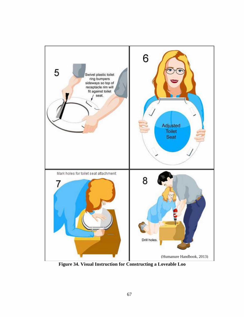
67
Figure 34. Visual Instruction for Constructing a Loveable Loo
(Humanure Handbook, 2013)

68
Appendix B: Constructing a UDDT Locally
A concrete mix is made using five parts clean river sand (50 litres) and one part cement
(10 litres). Alternately 3 parts river sand, 2 parts small stones and 1 part cement can be used. A
brick mould with dimensions 1.35 m long by 0.9 m wide by 75 mm deep (Figure 35) is used to
cast the concrete slab. An area, 450 mm long and 335 mm deep, is made for the step. Steel wires
are place in the concrete slab for reinforcement. The slab is left to cure for at least 2 days. It
should be kept wet for several days to cure properly (Morgan, 2007).
Figure 35. Brick Mould for Concrete Slab (Morgan, 2007)
A second slab with dimensions 1.2 m long and 0.9 m wide and about 40 mm deep (Figure
36) should be cast offsite using the same method as for the base slab (Morgan, 2007). When
placed directly on top of the vault, this slab will serve as the base for the toilet. Holes for the
pedestal and vent pipe can be cast in the slab by placing a bucket and metal cylinder in the
mould, respectively. The concrete mix should be added to the mould to half the slab height.
Reinforcing wires are to set in the mix. More mix is added for the remainder of the slab height.
The concrete should be smoothed down with a wooden float followed by a steel float (Morgan,
2007).
Figure 36. Brick Mould for Toilet Slab with Bucket and Metal Cylinder for Pedestal and
Vent Pipe Space (Morgan, 2007)
Using bricks on their edge and mortar, a vault is built on top on the concrete slab base
(Figure 37). If a 20 litre bucket is used the vault should be about 40 cm high. This will require
about 4 layers of bricks built on edge or about 6 layers built normally. The walls are built so that
the outer measurements of the top are 1.2 m x 0.9 m and the base 1.35 m x 0.9 m. This allows for
the slope at the back of the vault over which the vault access slab at the rear will be fitted (Figure
37). To support the rear end of the toilet slab placed on top the brick vault, a reinforced concrete
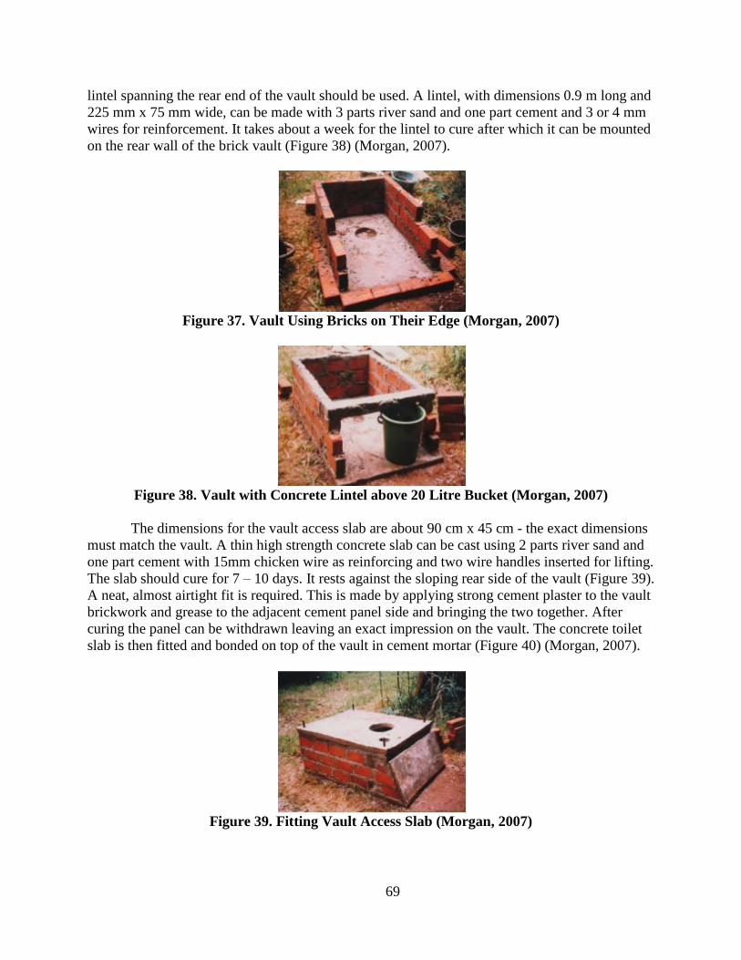
69
lintel spanning the rear end of the vault should be used. A lintel, with dimensions 0.9 m long and
225 mm x 75 mm wide, can be made with 3 parts river sand and one part cement and 3 or 4 mm
wires for reinforcement. It takes about a week for the lintel to cure after which it can be mounted
on the rear wall of the brick vault (Figure 38) (Morgan, 2007).
Figure 37. Vault Using Bricks on Their Edge (Morgan, 2007)
Figure 38. Vault with Concrete Lintel above 20 Litre Bucket (Morgan, 2007)
The dimensions for the vault access slab are about 90 cm x 45 cm - the exact dimensions
must match the vault. A thin high strength concrete slab can be cast using 2 parts river sand and
one part cement with 15mm chicken wire as reinforcing and two wire handles inserted for lifting.
The slab should cure for 7 – 10 days. It rests against the sloping rear side of the vault (Figure 39).
A neat, almost airtight fit is required. This is made by applying strong cement plaster to the vault
brickwork and grease to the adjacent cement panel side and bringing the two together. After
curing the panel can be withdrawn leaving an exact impression on the vault. The concrete toilet
slab is then fitted and bonded on top of the vault in cement mortar (Figure 40) (Morgan, 2007).
Figure 39. Fitting Vault Access Slab (Morgan, 2007)

70
Figure 40. Front View of Vault with Toilet Slab Placed on Top (Morgan, 2007)
The UDDT pedestal is constructed using a 20 L bucket, a 20 mm polyethylene bend, a
plastic toilet seat and cement, sand and wire. First the base of the bucket is sawn off squarely
(Figure 41). The base is then cut in half (Figure 42 and 43). One half is fitted within the bucket
about halfway up the walls at an angle (Figure 44). This serves as the urine diverter. The diverter
is secured by drilling small holes through the cut base halve and bucket walls and passing wire
through and tightening (Figure 45). For fitting the 20 mm polyethylene bend, a hole is drilled
through the bucket wall just above the base of the diverter. The bend is turned at an angle on the
outside (Figure 46 and 47) (Morgan, 2007).
Figure 41. Cutting off the Bucket Base (Morgan, 2007)
Figure 42. Marking base for Cutting (Morgan, 2007)

71
Figure 43. Cut Base Halves (Morgan, 2007)
Figure 44. Placing Urine Diverter (Cut Base Half) Half-way up Bucket at an Angle
(Morgan, 2007)
Figure 45. Attached Diverter with Wire (Morgan, 2007)
Figure 46. Fitting Pipe Bend to Bucket (Morgan, 2007)

72
Figure 47. Inside View of the Fitted Pipe Bend (Morgan, 2007)
A hot wire is used to drill holes through the plastic ribs which support the toilet seat
(Figure 48). Through these holes a wire is threaded in a loop under the seat (Figure 49). Concrete
from a mix of 3 parts river sand and 1 part cement is added to the underside of the toilet seat
(Figure 50). The concrete and wire will create a higher strength toilet seat that will form a bond
with the side walls of the pedestal (Morgan, 2007).
Figure 48. Using Hot Wire to Make a Hole through the Plastic Toilet Seat Ribs
(Morgan, 2007)
Figure 49. Toilet Seat with a Threaded Loop of Wire (Morgan, 2007)

73
Figure 50. Concrete Added to the Toilet Seat (Morgan, 2007)
The bucket is fitted centrally over the toilet seat, with the urine-diverting hold facing the
front of the toilet seat (Figure 51). Eight pieces of bent wire are introduced into the cement
supporting the seat (Figure 52). This is allowed to cure overnight. A mix of 3:1 sand and cement
is made and plastered half way up the walls of the bucket (Figure 53). This is left overnight to
cure (Morgan, 2007).
Figure 51. Bucket Fitted to Toilet Seat (Morgan, 2007)
Figure 52. Bent Wire around Toilet Seat (Morgan, 2007)

74
Figure 53. Concrete Added Half-way up Bucket (Morgan, 2007)
The rest of the bucket is cemented with the 3:1 mix after the bottom half cures (Figure
54). It is left to cure overnight. A mould to form the base of toilet pedestal can be made with
wood, about 60 cm x 60 cm and 40 mm deep (Figure 55). The bucket and seat are overturned
into a base mould, which is laid on top of a plastic sheet. The same 3:1 river sand and cement
mix is placed within the mould to create the base. Wire is added to both the base and coiled
around the pedestal (Figure 56). A final layer of the 3:1 mix is plastered up the side walls of the
pedestal over the wire. The final layer can be made with cement watered down to make a thick
paint and applied with a brush. The completely cemented pedestal should cure for several days
kept wet at all times (Figure 57). A plastic sheet and sacking can be used to cover the curing
toilet pedestal (Morgan, 2007).
Figure 54. Concrete Added to the Second Half of Bucket (Morgan, 2007)
Figure 55. Bucket and Seat within Base Mould (Morgan, 2007)

75
Figure 56. Wire Added for Reinforcement (Morgan, 2007)
Figure 57. Completely Cemented Pedestal Curing (Morgan, 2007)
A pliable putty should be applied to the space between the bucket side wall and urine
diverter. The putty is pressed into the gap from underneath (Figure 58). It is also be pressed into
the gap from the upper side (Figure 59). This seals the apparatus enabling urine to enter the urine
diverter and flow into the plastic bend. A plastic pipe is connected to the bend (Figure 60). The
pipe is led back over the concrete base of the urine-diverting pedestal to the rear of the toilet
(Figure 61). Once the concrete is completely cured and dry, a coat of enamel paint can be applied
to the pedestal to improve the aesthetics of the toilet system (Figure 62). The completely dry
pedestal is placed into the toilet slab and enclosed by a superstructure for privacy (Figure 63).
Superstructures can be made from bricks or timber, metal sheeting, asbestos sheeting, reeds,
grass or of any material that offers privacy. The urine pipe can be led into a soakaway or into a
vegetable garden, preferably beneath ground level. The urine can also be led to a plastic
container placed in a hole dug in the ground. The pipe can also be led to a tree, such as a banana
tree (Figure 64) (Morgan, 2007). Within the vault, feces is collected, such as in a 20 litre bucket.
Buckets are retrieved via the access slab located at the rear of the vault (Figure 65).
Figure 58. Urine Diverter Sealed from Bottom (Morgan, 2007)

76
Figure 59. Urine Diverter Sealed from Top (Morgan, 2007)
Figure 60. Attached Urine Pipe (Morgan, 2007)
Figure 61. Urine Pipe Led to Rear of Toilet (Morgan, 2007)
Figure 62. Painted Pedestal (Morgan, 2007)

77
Figure 63. Installed UDDT on Slab within Straw Superstructure (Morgan, 2007)
Figure 64. Urine Pipe Led to Banana Tree (Morgan, 2007)
Figure 65. View of Collection Bucket for Feces within Vault after Removing Access Slab
(Morgan, 2007)