a review of 5g/satellite compatibility studies in c-band
TRANSCRIPT

A review of 5G/Satellite compatibility studies
in C-band
LS telcom
LS telcom UK Ltd
18 King William Street
London EC4N 7BP
United Kingdom
Tel: +44 (0) 20 3740 6470
Fax: +49 (0) 7227 9535 605
Email: [email protected]
Internet: www.LStelcom.com
Contact person:
Mr. Richard Womersley
Managing Director
Tel: +44 (0) 20 3740 6470
Email: [email protected]
20 October 2021

A review of 5G/Satellite compatibility in C-band
© 2021 LS telcom AG October 26, 2021
Page 2/98
Table of Contents
Executive Summary ............................................................................................................................ 4
1 Introduction .................................................................................................................................. 6
1.1 Background ........................................................................................................................... 6
1.2 Structure of this document .................................................................................................... 6
2 Inputs and Outputs ....................................................................................................................... 8
2.1 Introduction ........................................................................................................................... 8
2.2 Compatibility methods ........................................................................................................... 9
2.3 Path loss ............................................................................................................................. 10
2.4 Input Assumptions and Parameters .................................................................................... 10
2.5 Outcomes ........................................................................................................................... 11
3 Analysis of the Results ............................................................................................................... 13
3.1 Introduction ......................................................................................................................... 13
3.2 Study Summary .................................................................................................................. 13
3.3 Co-Channel Analysis .......................................................................................................... 14
3.4 Adjacent Frequency Analysis .............................................................................................. 17
3.4.1 Emission Masks ........................................................................................................... 17
3.4.2 FSS Receiver Spectral Performance............................................................................ 21
3.4.3 LNB performance ......................................................................................................... 22
3.4.4 Separation Distances ................................................................................................... 23
3.4.5 Guard Bands ................................................................................................................ 25
3.4.6 LNB Saturation ............................................................................................................ 26
3.4.7 Impact of IMT User Equipment ..................................................................................... 26
4 Lessons learnt ............................................................................................................................ 28
5 Conclusions and Recommendations .......................................................................................... 30
5.1 Overview ............................................................................................................................. 30
5.2 Points to note from existing studies ..................................................................................... 30
5.3 Recommended Modelling Parameters ................................................................................ 31
6 Analysis of Studies ..................................................................................................................... 34
6.1 Introduction ......................................................................................................................... 34

A review of 5G/Satellite compatibility in C-band
© 2021 LS telcom AG October 26, 2021
Page 3/98
6.2 Individual Study Analysis .................................................................................................... 34
6.2.1 5G Cellular and Fixed Satellite Service Spectrum Coexistence in C-Band ................... 34
6.2.2 The Interference Mitigation Method and Field Test in C-Band Between 5G System and
FSS Receiver ............................................................................................................................. 36
6.2.3 IMT-FSS Coexistence Scenarios In C-Band ................................................................ 37
6.2.4 Best Practices for Terrestrial-Satellite Coexistence during and after the C-Band Transition
39
6.2.5 Coexistence for LTE-Advanced and FSS Services in the 3.5GHz Band in Colombia ... 40
6.2.6 Coexistence Studies between LTE System and Earth Station of Fixed Satellite Service in
the 3400-3600 MHz Frequency Bands in China ......................................................................... 42
6.2.7 Coexistence conditions of LTE-advanced at 3400–3600 MHz with TVRO at 3625–4200
MHz in Brazil .............................................................................................................................. 44
6.2.8 Interference Mitigation Technique for the Sharing between IMT-Advanced and Fixed
Satellite Service ......................................................................................................................... 46
6.2.9 Geographic Sharing in C-band ..................................................................................... 47
6.2.10 Report ITU-R M.2019 Sharing studies between IMT-Advanced systems and
geostationary satellite networks in the FSS in the 3 400-4 200 and 4 500-4 800 MHz frequency
bands 49
6.2.11 Report ITU-R S.2368-0 Sharing studies between IMT-Advanced systems and
geostationary satellite networks in the FSS in the 3 400-4 200 MHz and 4 500-4 800 MHz frequency
bands in the WRC study cycle leading to WRC-15 ..................................................................... 57
6.2.12 Report for GSMA on the mitigations required for adjacent frequency compatibility between
IMT and ubiquitous FSS Earth Stations in the 3.4 – 3.8 GHz frequency band ............................ 72
6.2.13 Assessments on and Recommendations to Enable the Electromagnetic Compatibility
between Public Mobile Services and Fixed Satellite Service Operating in the C-Band ............... 73
6.3 Summary of Studies ............................................................................................................ 75
6.3.1 Studies ......................................................................................................................... 75
6.3.2 5G Input Assumptions .................................................................................................. 78
6.3.3 FSS Input Assumptions................................................................................................ 82
6.3.4 Modelling Assumptions ................................................................................................ 84
6.3.5 Co-Channel Separation Distances ............................................................................... 86
6.3.6 Adjacent Frequency Separation Distances................................................................... 91
7 References ................................................................................................................................ 96
8 Acronyms and Abbreviations ...................................................................................................... 98

A review of 5G/Satellite compatibility in C-band
© 2021 LS telcom AG October 26, 2021
Page 4/98
Executive Summary
As the use of ever higher frequencies for mobile services becomes more widespread, pressure to find
spectrum has led to cases where proposed mobile bands need to share spectrum with existing services.
In order for this sharing to take place, it is necessary to carefully study the interactions between the
mobile service and the incumbent service or services. These studies are called compatibility studies
and aim to find a set of parameters which may be technical or practical, or even in some cases political,
which will allow the services to co-exist in the same frequency bands without causing harmful
interference.
One band which has proven particularly highly contested is the C-band (3400 – 4200 MHz), parts of
which have been identified by the International Telecommunications Union (ITU) for International Mobile
Telecommunications (IMT) services, more commonly called 5G. This band is home to a large number
of (space-to-Earth) satellite transmissions and, in many countries, fixed point-to-point or point-to-
multipoint services. Many organisations around the world have examined the question of whether and
how 5G systems can co-exist with terrestrial satellite receivers in the band. The results of these studies
vary significantly, providing little consistency which others could use to help them reach decisions on if
and how the two systems could co-exist side-by-side.
LS telcom has worked with a number of administrations, and industry bodies to consider the
compatibility between satellite and mobile services in the band, and have noticed that many of the
studies conducted yielded different results. We were curious as to why this was, and whether there
were differences in modelling inputs, assumptions or other aspects. In order to better inform our own
modelling, we decided to investigate what, if any, the commonalities and differences across the various
studies are, and if lessons can be learnt to enable more consistency in future studies. Full details of the
analysis are contained within the body of this report, however a summary of the observations is shown
below:
▪ Operating 5G services co-channel with C-band satellite receivers requires separation distances
measured in tens to hundreds of km, and the studies have all shown this to be the case. Unless C-
band usage is only at a few, very remote sites, this will preclude co-channel spectrum sharing in
almost all scenarios.
▪ Operating 5G service in channels adjacent to wanted C-band satellite signals introduces a range
of additional considerations. The out-of-band emissions from 5G transmitters and the potential for
overloading the receiver mean that this scenario requires very careful modelling to correctly
understand the impacts.
▪ Emissions masks for the IMT system vary considerably across the studies. A number of studies
make use of values from earlier standards, and as such may be of limited use in the current issue
of 5G FSS sharing. In addition, it is questionable whether mobile equipment manufacturers would
be motivated to exceed requirements beyond those in the 3GPP standards despite some studies
assuming that they would.
▪ LNBs are inherently wideband, being required to operate across the whole of the C-band, and as
such would not be expected to significantly attenuate 5G transmissions on adjacent frequencies
without additional filtering applied at the input to the LNB. Where filtering is applied to the LNB, it
would need to be sufficiently wideband to allow adequate operation within the remaining allocated

A review of 5G/Satellite compatibility in C-band
© 2021 LS telcom AG October 26, 2021
Page 5/98
FSS spectrum. A concern with the receiver spectral performances identified in a number of the
reports is the use of particularly narrow bandwidths. Optimistically narrow filters applied to the LNB
are unrealistic, and those applied at IF are not relevant to the issue of compatibility
▪ All of the thresholds which are defined with respect to satellite receiver performance (e.g. the non-
linearity compression point of the LNB, or an increase in I/N) represent limits at, and beyond which,
satellite reception will be impacted. As such, they should not be assumed to be targets to be met,
and similarly any results based on calculations using these limits will also represent the point at
which reception is degraded and not an average value to be used in, for example, determining
network roll-out parameters.
▪ Although higher elevation angles should reduce potential for interference, in practical installations,
reflections from nearby structures mean that this is not a usable mitigation to improve compatibility.
Considering that studies have shown that the theoretical rejection provided by increased elevation
angles does little to mitigate against 5G interference, it can be equally implied that AAS (for which
little study has yet been conducted) cannot be used to provide azimuthal protection of satellite
receivers as ceasing transmissions in a particular direction will, at best, provide a small reduction
in potential interference due to the large number of reflections of the main signals from nearby
structures.
▪ There is a trade-off between the size of any guard-band left between 5G and satellite services, the
necessary separation distance between transmitters and receivers, and the performance of any
filters fitted to the satellite receivers. Note that it is almost impossible to control the separation
distance between user devices and satellite dishes.
Any administrations wishing to conduct a technical compatibility study to determine the extent to which
C-band satellite services can co-exist with 5G services in the same band could, on the one hand, take
heed of the results of the range of existing studies, or could conduct their own calculations. However,
given the wide range of input assumptions used within studies, relying on them at a national level to set
sharing criteria is troublesome. As such, administrations wishing to make use of the existing studies
would be recommended to take caution to ensure they fully understand the limitations imposed by the
assumptions made. Instead, if administrations wish to conduct their own compatibility studies, a set of
recommended parameters (considering the conclusions and lessons learnt from the analysis) are
presented within the main body of this report.

A review of 5G/Satellite compatibility in C-band
© 2021 LS telcom AG October 26, 2021
Page 6/98
1 Introduction
1.1 Background
As the use of ever higher frequencies for mobile services becomes more widespread, many
organisations around the world have examined the question of whether and how 5G systems can co-
exist with satellite receivers in the C-band (3400 – 4200 MHz). The results of these studies vary
significantly, providing little consistency which others could use to help them reach decisions on if and
how the two systems could co-exist side-by-side.
LS telcom has conducted a number of studies examining these compatibility issues and as a result we
have noticed that there are a very wide range of results emanating from them. Such varying outcomes
could come from a range of areas including the inputs used, modelling assumptions, and study
parameters. To try and bring some clarity to the situation, and thus improve and inform our own
modelling, we thought it would be useful to compare the range of studies available to see:
▪ what the differences between them may be, and whether this might explain their varying results;
▪ if there are any commonalities amongst them; and
▪ whether it is possible to draw any conclusions which could then be of assistance to regulators and
administrations in taking their own decisions when considering 5G and satellite compatibility in C-
band.
The collection of studies has been analysed and high level observations and lessons learnt presented.
The outcome of our examination of these studies provides a stark warning to those wishing to better
understand the compatibility issues: our findings show that the studies take such a wide range of input
assumptions, relying on them at a national level to set sharing criteria is troublesome. We therefore
decided to publish the results of our assessments to assist others who may also want to better
understand co-existence of 5G and satellite services.
Based on the studies reviews, and our own work on these issues we have provided a recommended
set of parameters that provide a solid and repeatable basis for those wishing to conduct the analyses
for themselves.
1.2 Structure of this document
This document is structured as follows:
▪ Section 2 identifies the inputs and outputs, together with the associated modelling scenarios which
are required for a full compatibility analysis.
▪ Section 3 looks at the results of all of the studies and examines how their outputs compare.
▪ Section 4 discusses the lessons which can be learnt from the studies.
▪ Section 5 provides recommendations concerning international best practice in conducting
compatibility analyses.
▪ Section 6 documents all the input and output assumptions made in each study.

A review of 5G/Satellite compatibility in C-band
© 2021 LS telcom AG October 26, 2021
Page 7/98
▪ Section 7 lists reference documents use in the compilation of this report.
▪ Section 8 contains a list of acronyms and abbreviations which are used within this report.
A review of 5G/Satellite compatibility in C-band
© 2021 LS telcom AG October 26, 2021
Page 8/98
2 Inputs and Outputs
2.1 Introduction
The C-band (from 3400 to 4200 MHz) is a mainstay of satellite communications. From relaying the
pictures of the first moon landing in 1969 around the world, to providing broadband interconnectivity in
remote areas today, satellite use of the band provides crucial connectivity to a variety of commercial
and government entities.
In addition to supporting satellites, the band has also historically been used for terrestrial fixed links
who can share the band with the satellite downlinks by carefully selecting the location of the links so as
not to cause interference. More recently, these fixed services were extended to include fixed wireless
access using point-to-multipoint technology. These services typically provide domestic or enterprise
broadband internet connectivity and being fixed services could still be largely designed so as not to
cause harmful interference to satellite services.
Parts of the band have now been identified for International Mobile Telecommunications (IMT) services
at various previous ITU World Radiocommunication Conferences (WRC). Introducing such services
into the band is far more complex than for previous fixed services if satellite reception is to be protected
as:
▪ mobile base station transmissions are much higher powered;
▪ mobile base stations transmit in all directions and not just on a point-to-point basis;
▪ user devices can be anywhere, making controlling their proximity to satellite receivers nigh on
impossible.
A wide range of organisations have tried to determine how mobile services could share spectrum with
satellite services (and fixed services) and with a push towards using the band for 5G services, the
importance of finding workable solutions has never been greater. In this report we examine some of
the compatibility studies which have already attempted to address this issue, to try and tease out
international best practice when it comes to the sharing of the band.
There are two axes along which we will compare the various studies:
▪ the methods employed, and
▪ the input and modelling assumptions and parameters selected.
A review of 5G/Satellite compatibility in C-band
© 2021 LS telcom AG October 26, 2021
Page 9/98
2.2 Compatibility methods
C-band satellite transmissions and by dint, receivers, operate across the frequency range 3400 – 4200
MHz. Unmodified, devices called Low Noise Amplifiers (LNAs), also known as Low Noise Blocks
(LNBs)1 are designed to amplify the very weak signals from satellites to ensure that the receiver is
sensitive across this whole frequency range. There are two methods by which satellite receivers can
be affected such that they are no longer able to receive the satellite signals:
▪ emissions on the same (wanted) frequency to which the receiver is tuned may be sufficiently strong
to cause co-channel interference, or
▪ emissions anywhere within the LNB’s pass-band may be sufficiently strong to overload the LNB,
causing it to become non-linear and thereby impeding reception.
Depending on the band selected, 5G transmissions may occupy frequencies from 3300 – 4200 MHz:
▪ 3GPP Band n78 covers the range 3300 – 3800 MHz and is the band most commonly being
considered for wide area mobile services, and
▪ 3GPP Band n77 which extends the frequency range up to 4200 MHz is being considered in a few
countries for low-power campus type networks, and is partially used in the USA for mobile services.
Though the intended transmissions occupy the associated frequency ranges, the transmitters also
produce out-of-band emissions which are an unavoidable artefact of digital transmission systems and
occupy the spectrum either side of the intended transmission. Thus there are two parts of a 5G
transmission which may cause interference to satellite reception:
▪ the intended transmission, on the frequency on which the 5G transmitter is operating, and
▪ the out-of-band emissions on frequency adjacent to that on which the 5G transmitter is operating.
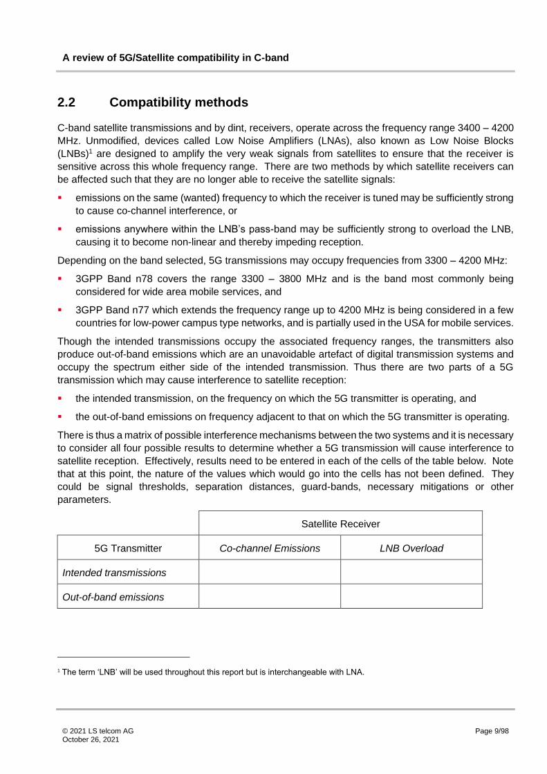
There is thus a matrix of possible interference mechanisms between the two systems and it is necessary
to consider all four possible results to determine whether a 5G transmission will cause interference to
satellite reception. Effectively, results need to be entered in each of the cells of the table below. Note
that at this point, the nature of the values which would go into the cells has not been defined. They
could be signal thresholds, separation distances, guard-bands, necessary mitigations or other
parameters.
Satellite Receiver
5G Transmitter Co-channel Emissions LNB Overload
Intended transmissions
Out-of-band emissions
1 The term ‘LNB’ will be used throughout this report but is interchangeable with LNA.
A review of 5G/Satellite compatibility in C-band
© 2021 LS telcom AG October 26, 2021
Page 10/98
2.3 Path loss
If the level of 5G transmissions, and the thresholds at which the satellite receiver will suffer interference
can be determined (see the section on input parameters below), then assuming that the 5G transmitter
and satellite receiver are not co-located, it is necessary to determine the path loss between them. There
are several path-loss models which could be used, typically one of the following are usually applied:
▪ Free space path loss – this is valid, as the name suggests, in free space only (i.e. where there is a
clean line of sight between the transmitter and receiver and there are no incursions into the Fresnel
zone). In real life situations, free space path loss is typically only valid at distances up to a few tens
(or in some cases hundreds) of metres.
▪ ITU-R Recommendation P.452 [1] “Prediction procedure for the evaluation of interference between
stations on the surface of the Earth at frequencies above about 0.1 GHz” - is more appropriate in
typical situations where a path is obstructed, but does not provide particularly accurate results at
short distances (i.e. <500m).
Many other models exist which may be applicable as long as the author of a study understands their
application and limitations.
In addition, if it is assumed that 5G transmitters are operated indoors, it is also necessary to define the
additional path loss (if any) which would be provided by the structure and composition of the building
including windows and doors. ITU-R Recommendation P.2019 [2] provides one such method.
Finally there is the question of the many or the few. 5G transmitters do not exist in solitude, they are
part of a wider network. Considering compatibility between one 5G transmitter and one satellite receiver
is therefore not a complete picture and it is necessary to determine how multiple 5G transmitters will
impact satellite reception. This is particularly important when understanding that the various thresholds
which are often used in compatibility studies represent the points at which harmful interference will
occur. Thus, setting parameters in which one site will reach these thresholds will inevitably mean that
more than one site will exceed them, and thus interference will occur.
2.4 Input Assumptions and Parameters
For the satellite receiver, there are a wide range of input parameters which need to be considered in
order to determine compatibility. These include parameters associated with the reception of the
satellite:
▪ the e.i.r.p. of the satellite being received;
▪ the size (or gain) of the receiving satellite dish and its efficiency and radiation pattern;
▪ the noise figure (or noise temperature) of the LNB;
▪ the angle of elevation and azimuth of the dish;
▪ the reception bandwidth.

A review of 5G/Satellite compatibility in C-band
© 2021 LS telcom AG October 26, 2021
Page 11/98
In addition, it is also necessary to understand the performance characteristics of the LNB to determine
the point at which it would become overloaded:
▪ the gain of the LNB;
▪ its 1 dB compression point (this is the point at which the gain of the LNB falls by 1 dB as it is
reaching saturation). Note that it is generally regarded that an LNB will enter a non-linear point at
10 dB below the 1 dB compression point, and that this lower level should never be exceeded;
▪ the frequency range over which it operates (the ‘pass-band’);
▪ the performance of any filter fitted before (or built in to) the LNB.
A decision needs to be made concerning the extent to which the 5G interference will be permitted to
affect satellite reception. The usual metric for this is the level of additional interference caused by the
5G signal compared to that already experienced by the satellite receiver, measured as C/(I+N) where
C is the wanted carrier, I represents interference and N represents noise. Additional 5G interference
will increase the ‘I’ in the equation and thus reduce the overall C/(I+N). The extent to which any such
reduction is allowed depends on the choice of the administration. The permitted increase in I caused
by 5G transmissions is usually referenced to the level of N and may, or may not, include temporal
variances (i.e. the percentage of time for which the value is exceeded). Without any temporal variance
being specified, the default value is 50% of the time. A requirement not to exceed an increase in I/N of
-12 dB for more than 5% of the time is therefore significantly stricter than a limit of just -12 dB.
For the 5G transmitter, the following parameters must be known:
▪ the intended transmission power (e.i.r.p);
▪ the intended transmission bandwidth;
▪ the level of out-of-band emissions and their frequency profile.
It is common to factor transmission bandwidth and transmission power, including for out-of-band
emissions, in the form of power per bandwidth (i.e. dBm/MHz). However there can be differences
between both the numerator and denominator, such as dBW/MHz, dBW/5 MHz, or dBm/100 kHz and
care must be taken to accurately translate between these.
2.5 Outcomes
The results of compatibility studies can be specified in a number of mutually non-exclusive ways:
▪ an increase in I/N resulting in a reduction in C/(I+N);
▪ a guard-band which needs to be left between the band in which satellite reception is protected and
that in which 5G transmissions are permitted;
▪ emissions limits on the intended or out-of-band limits of the 5G transmissions;
▪ interference thresholds which should not be exceeded at a satellite earth station location; and
▪ separation distances which must be met between any 5G transmitters and any satellite earth
stations.
A review of 5G/Satellite compatibility in C-band
© 2021 LS telcom AG October 26, 2021
Page 12/98
In addition, it may be necessary to introduce mitigations against interference from the 5G transmissions
into the satellite receivers (i.e. fitting filters to satellite receivers in order to protect them from 5G
transmissions), and the definition and specification of those mitigations may also form part of the results
of a study.

A review of 5G/Satellite compatibility in C-band
© 2021 LS telcom AG October 26, 2021
Page 13/98
3 Analysis of the Results
3.1 Introduction
This section investigates the extent to which trends exist across the compatibility studies examined.
Studies were identified through a detailed literature review aiming to find all relevant, published studies
from ITU, industry and academic sources. Inclusion in the analysis was dependent on the study quoting
results and input parameters which permitted comparisons to be made. Note that a small number of
more general recommendation documents, for example ECC Report 254, have not been included on
this basis. A detailed consideration of each individual study is given within section 6.2.
The analysis presented here considers a number of areas, looking first to co-channel operation of 5G
and FSS systems and the separation distances found to be required, before moving onto adjacent
frequency operation of the two systems, and the additional considerations that need to be factored into
the studies. The extent to which studies utilise the same parameters is investigated, particularly with
regards to 5G emissions masks and FSS receiver masks, before considering the impact on the
separation distances and guard bands that are found to be required. Where consensus is not found
across the studies, suggestions are made as to how usable recommendations regarding possible 5G
implementation within C-band might be found.
3.2 Study Summary
The tables below provide a summary of which studies have considered the issues of spurious
emissions, satellite receiver spectral performance and LNB overload.
Reference Chapter
Reference Organisation
Spurious Emissions
Filter Performance
LNB Overload
[3] 6.2.1 Academia ✓ ✓ ✓
[4] 6.2.2 Industry ✓ ✓ ✓
[5] 6.2.3 Industry ✗ ✗ ✗
[6] 6.2.4 National Administration/
Industry ✓ ✓ ✓
[7] 6.2.5 Academia ✗ ✗ ✗
[8] 6.2.6 Academia ✓ ✗ ✓
[9] 6.2.7 National Administration
✓ ✗ ✓
[10] 6.2.8 Academia ✗ ✗ ✗
[11] 6.2.9 National Administration
✓ ✓ ✗

A review of 5G/Satellite compatibility in C-band
© 2021 LS telcom AG October 26, 2021
Page 14/98
Reference Chapter
Reference Organisation
Spurious Emissions
Filter Performance
LNB Overload
[12] 6.2.10.3 ITU ✓ ✗ ✗
[12] 6.2.10.4 ITU ✓ ✗ ✗
[12] 6.2.10.5 ITU ✓ ✗ ✗
[12] 6.2.10.6 ITU ✓ ✗ ✗
[12] 6.2.10.7 ITU ✓ ✗ ✗
[12] 6.2.10.9 ITU ✓ ✗ ✓
[13] 6.2.11.1 ITU ✗ ✗ ✗
[13] 6.2.11.2 ITU ✓ ✗ ✓
[13] 6.2.11.3 ITU ✓ ✗ ✓
[13] 6.2.11.4 ITU ✓ ✗ ✓
[13] 6.2.11.7 ITU ✓ ✓ ✗
[13] 6.2.11.8 ITU ✗ ✗ ✗
[13] 6.2.11.10 ITU ✓ ✓ ✗
[14] 6.2.12 Industry ✓ ✓ ✓
[15] 6.2.13 National Administration/
Industry ✓ ✓ ✓
3.3 Co-Channel Analysis
Within the co-channel studies investigated, there is large variation in both the input and output
parameters. EIRPs range from 11dBm/MHz to 57dBm/MHz, with a range of base station and receiver
conditions. Studies typically make use of ITU-R P.452 for modelling the propagation related to the IMT
service (12, 14, 15 or 16) although one also relies on ITU-R P.2001. Various diffraction models are
used, along with various terrain and clutter databases (with some models utilising a smooth Earth
approach). There is nominal agreement in parameters within the two ITU study reports that have been
considered.
A plot of the worst case separation distance (i.e. the largest co-channel separation distance per study
within a given elevation angle range: 0-20⁰, 20-40⁰ and 40+⁰) against the highest EIRP for a study
(normalised to represent a constant I/N and such that the IMT transmission and FSS receiver
bandwidths align) is shown below:

A review of 5G/Satellite compatibility in C-band
© 2021 LS telcom AG October 26, 2021
Page 15/98
Figure 1: Co-channel studies normalised EIRP vs separation distance for each elevation angle range
Trend lines are included also (least squares fit, standard linear Excel trendline). This may be an
oversimplification of the situation, however as a linear relationship exists between distance and free
space path loss (in a logarithmic scale such as dB), it is assumed to be valid. Whilst the trend lines do
show the expected trend, i.e. an increase in EIRP of an IMT base station results in an increased
separation distance between IMT and FSS, the range of values within the studies considered means
the fit of the trendline is weak (R2 of 0.14 to 0.2).
As a number of the study values are grouped, with a small number of values looking to be outliers, there
is potentially an argument in omitting these values. Indeed, looking at the studies resulting in outliers,
one [7] (considered in 6.2.5) makes use of ITU-R P.2001 rather than ITU-R P.452 for the propagation
model. ITU-R P.2001 is applicable for 30MHz to 50GHz, and for distances of 3km to at least 1,000km,
and therefore may not be explicitly comparable with results obtained using ITU-R P.452. The results
from [8] (considered in 6.2.6) are omitted as the resulting separation distances are significantly larger
than for other studies without a clear reason as to why. Earth stations have been chosen in [13] (chapter
reference 6.2.11.8) specifically to highlight the effect of terrain close to the FSS earth station on the
resulting separation distance. Within the study, the earth station resulting in the large separation
A review of 5G/Satellite compatibility in C-band
© 2021 LS telcom AG October 26, 2021
Page 16/98
distances, Madley in the UK, was chosen precisely because it has little natural terrain screening. Note
that the other UK station examined, Brookmans Park, is quoted as having higher levels of terrain
screening but does still result in large separation distances also.
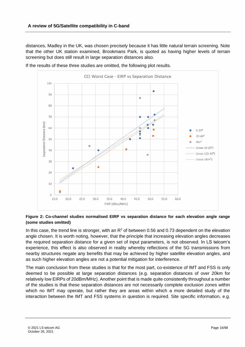
If the results of these three studies are omitted, the following plot results.
Figure 2: Co-channel studies normalised EIRP vs separation distance for each elevation angle range
(some studies omitted)
In this case, the trend line is stronger, with an R2 of between 0.56 and 0.73 dependent on the elevation
angle chosen. It is worth noting, however, that the principle that increasing elevation angles decreases
the required separation distance for a given set of input parameters, is not observed. In LS telcom’s
experience, this effect is also observed in reality whereby reflections of the 5G transmissions from
nearby structures negate any benefits that may be achieved by higher satellite elevation angles, and
as such higher elevation angles are not a potential mitigation for interference.
The main conclusion from these studies is that for the most part, co-existence of IMT and FSS is only
deemed to be possible at large separation distances (e.g. separation distances of over 20km for
relatively low EIRPs of 20dBm/MHz). Another point that is made quite consistently throughout a number
of the studies is that these separation distances are not necessarily complete exclusion zones within
which no IMT may operate, but rather they are areas within which a more detailed study of the
interaction between the IMT and FSS systems in question is required. Site specific information, e.g.

A review of 5G/Satellite compatibility in C-band
© 2021 LS telcom AG October 26, 2021
Page 17/98
terrain and clutter surroundings, exact transmission and receive parameters and so on, are likely to be
available in specific cases, and as such these are likely to produce potentially more meaningful and
useful results than generic approaches.
3.4 Adjacent Frequency Analysis
Within the adjacent frequency studies investigated, there is large variation in both the input and output
parameters. EIRPs range from 11dBm/MHz to 65dBm/MHz, with a range of base station and receiver
conditions. Studies typically make use of ITU-R 452 for modelling the IMT service (12, 14, 15 or 16)
although one model also makes use of ITU-R 2001. Various diffraction models are used, along with
various terrain and clutter databases (with some models utilising a smooth Earth approach). There is
nominal agreement in parameters within the two ITU study reports that have been considered.
3.4.1 Emission Masks
A range of standards are used to determine the appropriate IMT emission masks to be used within the
studies. For example, the ITU reports ITU-R S.2368 [13] (chapter reference 6.2.11) and ITU-R M.2019
[12] (chapter reference 6.2.10) recommend use of ACLR tables taken from 3GPP Document TS 36.104
v.11.2.0 and 3GPP Document TS 25.104 respectively, reproduced below. There are additional tables
within these standards stating operating band limits not specific to adjacent IMT channels. These do
not appear to have been used for the most part, however these are the most appropriate values to use
in the case of interference to services other than adjacent frequency IMT (i.e. FSS), except in the
specific case where the IMT and FSS systems are immediately spectrally adjacent and the spectral
separation (including any guard band) is within the ACLR limits stated. In the case of ITU-R S.2368, an
absolute limit is also stated for each base station type which is to be taken if it is less stringent than the
limits shown below.

A review of 5G/Satellite compatibility in C-band
© 2021 LS telcom AG October 26, 2021
Page 18/98
Figure 3: Out of band emissions parameters taken from 3GPP Document TS 36.104 v.11.2.0 used in ITU-
R S.2368
Figure 4: Out of band emissions parameters taken from 3GPP Document TS 25.104 used in ITU-R
M.2019
The more recent 3GPP standard TS 38.104 V16.6.0 requires that, within the operating band, the
following must apply for a ‘Wide Area category A’ base station:
Figure 5 – Spurious emissions parameters taken from 3GPP Document TS 38.104

A review of 5G/Satellite compatibility in C-band
© 2021 LS telcom AG October 26, 2021
Page 19/98
Outside of the operating band2, TS 38.104 V16.6.0 requires that the following spurious emissions limits
must apply for a ‘Wide Area Category A’ base station:
Figure 6: Out of band emissions parameters taken from 3GPP Document TS 38.104
The limits are varied dependent on the base station type, however only the limits for a ‘Wide Area
Category A’ base station are reproduced here for the sake of brevity. Stricter limits apply for co-located
base stations, or for coexistence with IMT systems in different 3GPP bands (e.g. base stations operating
in 3GPP band n78 (3.3–3.8GHz), must comply with a limit of -52dBm/MHz within 3GPP band n79 (4.4–
5.0GHz). [15] for example makes use of this value, although appears to apply it to unwanted emissions
within the same band rather than at the next band. However, as no guarantee can be made within these
studies that such a scenario will result, the general limits should be taken.
A comparison of these three sets of limits is shown below for an ‘Wide Area Category A’ base station
with a transmitter power of 59dBm/MHz, operating within a 20MHz bandwidth:
2 Note that as 3GPP band n77 (3.3 – 4.2 GHz) and n78 (3.3 – 3.8 GHz) occupy at least part of the same spectrum, it could be expected that equipment would be manufactured that is suitable for operation in both bands rather than manufacturers having to produce greater amounts of equipment, i.e. equipment compliant with the limits for n77 could potentially be expected to meet the limits imposed on equipment compliant operation in n78.

A review of 5G/Satellite compatibility in C-band
© 2021 LS telcom AG October 26, 2021
Page 20/98
Figure 7: Out of band emissions masks from various 3GPP standards, assuming a 20MHz channel
bandwidth and a transmitter power of 59dBm/MHz
As can be seen, the values taken in the ITU studies from the older 3GPP standards in fact require
equipment to meet more stringent out of band emissions than those in the more recent TS 38.104 (by
over 20dB in some cases). In this regard then, use of the older 3GPP standards within 5G sharing
studies (TS 36.104 being relevant to Evolved Universal Terrestrial Radio Access (E-UTRA), and TS
25.104 being relevant to Universal Mobile Telecommunications System (UMTS)) are likely to present a
different result to those conducted using TS 38.104 (relevant to 5G NR). The majority of studies (other
than a small number of the most recent studies, [3] [6] [14], which make use of at least parts of 3GPP
TS 38.104) make use of the older transmission standards, potentially even erroneously, and as such
are arguably not applicable to the current issue of 5G FSS sharing.
The same is true of studies making use of masks considered to be more representative of actual
equipment. As no general guarantee can be made for the out of band emissions performance of
transmission equipment other than the limits set within the relevant 3GPP standards, the standards are
the only applicable limits that can be taken.

A review of 5G/Satellite compatibility in C-band
© 2021 LS telcom AG October 26, 2021
Page 21/98
3.4.2 FSS Receiver Spectral Performance
As with the other parameters investigated, there is little consensus on the appropriate spectrum mask
for the FSS receiver. A number of studies either do not quote specific values taken within the analysis
or describe the performance as ‘ideal’. Within the studies that do quote filter performance,
representations of the assumed masks are shown below (normalised for a receiver bandwidth of
20MHz). Note that for the Transfinite studies assuming use of a Gaussian filter, the form of the filter has
been estimated based on parameters provided within the report. However, as the report only includes
performance up to twice the bandwidth, the values beyond this reproduced here are not necessarily
correct.
Figure 8: FSS receive spectrum mask representations
As can be seen, the variation in FSS receiver mask performance is large, with some studies assuming
a cliff edge transition at the edge of the FSS receiver bandwidth, some assuming a more gradual
transition, and some assuming stepped changes a certain spectral distance from the carrier frequency.
The studies considered investigate performance of a number of different receivers (small TVRO type
installations, VSAT receivers, larger earth station type receivers etc.) and as such it is not surprising
that there is a range in assumptions for filter performance.
A number of studies do make the point that representative spectrum masks for FSS receivers are not
readily available. This is demonstrative of a potential concern regarding the bandwidth of filters
assumed within a number of the studies.

A review of 5G/Satellite compatibility in C-band
© 2021 LS telcom AG October 26, 2021
Page 22/98
Notwithstanding all of the above, any filters fitted at the intermediate frequency (IF) within satellite
receivers themselves will have virtually no impact on compatibility and do not represent valid input
assumptions when conducting compatibility studies. This is due to the fact that the interference
presented by 5G systems is at the LNB itself, and no amount of filtering after the LNB (i.e. in the
receiver) will change the levels at the dish itself. Many of the studies do not make clear whether the
filter responses being used are at the receiver or at the LNB.
3.4.3 LNB performance
LNBs are inherently wideband, being required to operate across the whole of the C-band, and as such
would not be expected to significantly attenuate 5G transmissions on adjacent frequencies without
additional filtering applied at the input to the LNB. As such, some of the responses assumed for the
FSS spectral performance in a number of the studies are likely to be overly optimistic when considering
unfiltered LNBs.
Where filtering is applied to the LNB, it would need to be sufficiently wideband to allow adequate
operation within the remaining allocated FSS spectrum. A concern with the receiver spectral
performances identified in a number of the reports is the use of particularly narrow bandwidths, e.g.
curves providing high levels of attenuation at twice the receive channel bandwidth as assumed in [14]
[11]. Whilst such filtering at either edge of the band may be appropriate, the use of such a narrow filter
could not be assumed to provide adequate performance over the rest of the FSS spectrum. Such narrow
bandwidth filters may be appropriate if assumed at IF, however, as stated previously, these would not
have a bearing on the results of this sort of compatibility analysis.
Across the studies, only a small number specify that the filter is fitted to the LNB [3] [4], the other studies
do not specify at what point in the receive chain the filter is fitted, i.e. at RF or IF. As saturation and
blocking effects occur prior to the IF section of the receive chain, the RF response of the earth station
is the important consideration. A further potential concern then is that as a number of the studies do not
explicitly consider LNB saturation, it may be that the exact location in the receive chain of any filter has
not been considered.
Hence it is important that studies consider the implications of their assumptions regarding filtering.
Optimistically narrow filters applied to the LNB are unrealistic, and those applied at IF are not relevant
to the issue of compatibility. In any case, the range of input assumptions mean that general limits and
approaches are difficult to produce, and investigation on a case by case basis is likely to be necessary.

A review of 5G/Satellite compatibility in C-band
© 2021 LS telcom AG October 26, 2021
Page 23/98
3.4.4 Separation Distances
Notwithstanding the differences in study input parameters observed within the previous sections, the
same comparison of base station EIRP and resulting separation (as presented within the co-channel
case) is shown below for the adjacent frequency case. Again, least squares fit trend lines have been
applied on the assumption that a linear fit is appropriate.
Figure 9: Adjacent frequency studies normalised EIRP vs separation distance for each elevation angle
range
As with the co-channel case, the spread of values is such that the trends are unlikely to be of great
value in producing recommendations for implementation of 5G and the separation distances that would
be required to protect FSS. This is not surprising given the large variation seen in the input parameters,
particularly around out of band emissions and satellite filter performance. As with the co-channel case,
the removal of outliers helps to strengthen the trend somewhat. Removal of the outliers represented by
the results of [7] [8] (chapter reference 6.2.5 and 6.2.6), again on the basis of the use of ITU-R P.2001
rather than ITU-R P.452, results in the following (noting that study [13], chapter reference 6.2.11.8 does
not quote adjacent frequency separation distances, and hence is not included in this plot):

A review of 5G/Satellite compatibility in C-band
© 2021 LS telcom AG October 26, 2021
Page 24/98
Figure 10: Adjacent frequency studies normalised EIRP vs separation distance for each elevation angle
range (some studies omitted)
Removal of the outliers does help to improve the trend, i.e. increasing the EIRP increases the required
separation distance. However, considering the range of separation distances quoted across the studies,
it is clear that there is unlikely to be sufficient consensus from which to derive actual recommendations
to be used in the implementation of 5G systems. Taking just the example of the two data points
associated with a corrected EIRP of 25dBm/MHz ( [13], chapters 6.2.11.7 and 6.2.11.10), the derived
separation distances vary by a factor of around 500. Whilst there are some differences in the studies,
such as slightly different out of band emissions for IMT and FSS receiver masks, it is not expected that
these could account for such a large difference in results (note that the results here are assumed to
correspond to the 0 MHz guard band case, i.e. the highest resulting separating distance).
As such, where studies utilising nearly the same parameters are unable to reach a consensus on the
results, it is unlikely that achieving a consensus on generally applicable recommended parameters to
be used in actual implementations is likely to be possible. As in the co-channel case, it is more likely
that detailed investigation of specific cases is likely to produce the most useful and meaningful results.

A review of 5G/Satellite compatibility in C-band
© 2021 LS telcom AG October 26, 2021
Page 25/98
3.4.5 Guard Bands
Guard bands between 0 MHz and 100 MHz have been considered within the studies. Plotting the guard
band against the separation distance required (again omitting the results from [7] and [8], chapter
references 6.2.5 and 6.2.6 respectively), yields the following results:
Figure 11: Guard band assumed (MHz) versus resulting separation distance
There is a trend to the data that is as expected, i.e. an increasing guard band decreases the required
separation distance. Similarly, the lower the elevation angle, the larger the separation distance required
for a given guard band however a number of studies find that the separation distance remains largely
constant for increasing guard bands. Indeed, when the frequency separation is such that interference
from IMT into the FSS receiver is within the spurious emissions domain, the limit is constant until the
next operating band. As such an increase in guard band would not be expected to reduce the emissions
or the separation distance required. As the studies have utilised a wide range of values for out of band
emissions and FSS receiver masks, a lack of agreement on the relationship between guard band and
separation distance would be expected.
In addition, this analysis takes no account of differing EIRPs, and as such only minimal correlation
would be expected given the range of input EIRPs considered. As with separation distances, detailed
investigation would need to be conducted regarding guard band requirements given the updated
parameters.

A review of 5G/Satellite compatibility in C-band
© 2021 LS telcom AG October 26, 2021
Page 26/98
3.4.6 LNB Saturation
Only a small number of the studies have considered LNB saturation explicitly. Within these, the
assumed value for the input power required to saturate the LNB is in the region of -60dBm. An important
point to note with regards to LNB saturation however is the implications of the input assumptions. If
non-linear behaviour of the LNB is assumed to result at 10dB below the 1dB compression point, and
this value is used as an input to the studies, the resultant protection criteria will be generated assuming
non-linear operation of the LNB.
LNBs are not designed to operate at this level. Indeed the 1dB compression point is an indicator of
departure from linearity and does not in itself provide information as to the level of unwanted mixing or
intermodulation products. As such, use of this value represents out of specification performance and
any separation distances calculated using this value will allow for 5G implementations that cause
satellite systems to be on the edge of failure. As such, separation distances calculated using this value
should be regarded as limits, not targets.
Within the studies, the 1dB compression point is typically used and the calculated separation distances
vary quite considerably. [9] (considered in 6.2.7) finds, for example, that coexistence of IMT and TVRO
FSS receivers is not possible with an LNB saturation point of -60dBm for anything other than small
urban cells unless the elevation angle is greater than 40⁰ (noting our previous comment that elevation
angles are unlikely to yield useful protection given reflections and other factors). If the saturation point
can be increased to -45dBm, coexistence is found to be possible, although never at a separation
distance of less than around 100m.
This agrees to some extent with the findings of other studies. [13] (considered in 6.2.11.4, taking a
saturation value of -60dBm) finds that separation distances of around 9km are required at lower
elevation angles (0-20⁰), reducing to around 6km when elevation angles increase (20-40⁰). [12]
(considered in 6.2.10.4, taking a saturation value of -61 dBm) finds that separation distances of 9.5km
are required for all elevation angles.
Despite only a small number of studies considering the issue however, what is clear is that, in cases
where no filters are fitted to satellite receivers, the separation distances required to allow the FSS
receiver LNB to operate at the edge of failure are of a similar order to, or sometimes larger than, those
required to meet the I/N requirements. Indeed with so few results, any recommendations are unlikely
to be generally applicable but the studies completed so far do highlight the issue to be as important as
I/N degradation, and highlight the need for it to be considered in detail.
3.4.7 Impact of IMT User Equipment
The majority of the studies examined do not consider user equipment. Those that do typically find that
the separation distances required for user equipment are, perhaps not unexpectedly, smaller than those
required for base stations. Co-channel analysis finds separation distances of anywhere between 500m
and 2.65km are required. For adjacent frequency operation, separation distances between 100m and
32.5km are found. The range of values again does not lend itself to the generation of useful generally
applicable recommendations for administrations to use. In addition, enforcing required separation
distances for user equipment is likely to be far more challenging for administrations than for base

A review of 5G/Satellite compatibility in C-band
© 2021 LS telcom AG October 26, 2021
Page 27/98
stations. As such, it is again likely that the most useful recommendations will result from specific
compatibility studies rather than the general set of studies considered here.

A review of 5G/Satellite compatibility in C-band
© 2021 LS telcom AG October 26, 2021
Page 28/98
4 Lessons learnt
From the studies examined, co-channel operation of FSS and IMT is considered to be unlikely to be
possible in most scenarios. Despite the range of input values to the studies, there is a general
consensus that typically 10s of km separation are required for all but the lowest EIRP values for IMT
base station transmitters. Whilst in some cases these separation distances might be possible to
achieve, or indeed lower separation distances may be feasible due to local effects such as terrain
screening, in depth analysis on a case-by-case basis would be required to identify these specific areas.
For out-of-band emissions, various values have been used in the studies, including some thresholds
arbitrarily defined by national administrations, and many which use older emissions standards that are
not applicable to new 5G systems. However, in order to comply with the 3GPP standards (and thus
bring their equipment to market), manufacturers need only meet the requirement specified in the 5G
3GPP standards themselves. For active antenna systems (AAS), where the transmitters are connected
directly to the antennas within the antenna casing itself, fitting any additional filtering to reduce out-of-
band emissions would be extremely costly, would add to the weight and may impair the operation of
the AAS. As such, for the purposes of calculating compatibility, only the emissions specified in the
3GPP standards can be safely applied.
Though national administrations may unilaterally decide to apply different thresholds, it is questionable
whether manufacturers would be motivated to meet such requirements. In particular, there is little to no
likelihood of manufacturers specially modifying mobile handsets to reduce their out-of-band emissions
for one country, unless the market in that country is sufficiently large (i.e. China).
With regards to FSS receiver performance, there is little consensus between the studies, other than to
state that representative FSS receiver and filter masks are difficult to obtain. As explored previously,
this is likely due to the inherently wideband nature of LNBs. To obtain reliable information applicable
within a given country however, it is likely that a more detailed set of FSS parameters will be required,
based on measurements of the actual equipment in use which may vary depending on the use to which
C-band satellite services are being put. It is also important that the location of any specified filters within
the receive chain, and the practicality of their assumed frequency response, are well understood by
study authors. Optimistically narrow filters applied to the LNB are unrealistic, and those applied at IF
are not relevant to the issue of compatibility
For separation distances for adjacent frequency operation of IMT and FSS, the majority of studies still
find large separation distances are required for higher power IMT base stations. While some studies do
find shorter separation distances are possible, just as many find that large, multiple kilometre separation
distances are required. Regardless, the wide range of input parameters assumed across the studies is
unlikely to yield consensus on the appropriate separation distances required.
The same is true of guard bands. There is a slight trend associated with the data that shows increasing
guard bands requiring shorter separation distances, but the range of input parameters considered
means that useful conclusions are difficult to draw. Rather, it may be better practice to consider real-
life implementations around the world of 5G within these bands and consider the levels of success that
have been experienced.
Few studies consider the impact of LNB saturation explicitly. Those that do typically find that in cases
where no filter is fitted to the LNB, the required separation distances are at least of an order with those

A review of 5G/Satellite compatibility in C-band
© 2021 LS telcom AG October 26, 2021
Page 29/98
required to meet I/N degradation requirements. The importance of the issue is highlighted however,
paticularly with regards to the selection of an input value for LNB saturation. Inputs using the 1dB
compression point allow for IMT implementations that could result in satellite systems operating at the
edge of failure. These values should be regarded as limiting separation distances, rather than targets.

A review of 5G/Satellite compatibility in C-band
© 2021 LS telcom AG October 26, 2021
Page 30/98
5 Conclusions and Recommendations
5.1 Overview
Any administrations wishing to conduct a technical compatibility study to determine the extent to which
C-band satellite services can co-exist with 5G services in the same band, could, on the one hand, take
heed of the results of the range of existing studies, or could conduct their own calculations.
As has been indicated in the previous section, the studies available take such a wide range of input
assumptions, that relying on them at a national level to set sharing criteria is troublesome. In this section
we have tried to summarise the lessons which can be learnt from the various compatibility studies, as
well as providing a set of parameters which should be used if attempting to revisit or calculate
compatibility criteria afresh.
5.2 Points to note from existing studies
If taking heed of the existing studies, the following results represent the most common outcomes:
▪ Operating 5G services co-channel with C-band satellite receivers requires separation distances
measured in tens to hundreds of km, and the studies have all shown this to be the case. Unless C-
band usage is only at a few, very remote sites, this will preclude co-channel spectrum sharing in
almost all scenarios.
▪ Operating 5G service in channels adjacent to wanted C-band satellite signals introduces a range
of additional considerations. The out-of-band emissions from 5G transmitters and the potential for
overloading the LNB mean that this scenario requires very careful modelling to correctly understand
the impacts.
▪ Although higher elevation angles should reduce potential for interference, in practical installations,
reflections from nearby structures mean that this is not a usable mitigation to improve compatibility.
The ITU standard states that the gain of a dish is -10 dBi at any angle greater than about 45° from
the boresight. This may hold true for large dishes, however for smaller ones typical of, for example,
direct-to-home television reception, it is an optimistic assumption.
▪ Considering that studies have shown that the theoretical rejection provided by increased elevation
angles does little to mitigate against 5G interference, it can be equally implied that AAS cannot be
used to provide azimuthal protection of satellite receivers as ceasing transmissions in a particular
direction will, at best, provide a small reduction in potential interference due to the large number of
reflections of the main signals from nearby structures which otherwise occur3.
▪ There is a trade-off between the size of any guard-band left between 5G and satellite services, the
necessary separation distance between transmitters and receivers, and the performance of any
3 In studies conducted by LS telcom, it was found that the amount of additional path loss between a transmitter and receiver
increased by, on average, no more than 6 dB when AAS was used to try and provide azimuthal protection due to scatter and reflections from nearby buildings. In addition, whilst the wanted signal from a 5G AAS transmitter has a defined radiation pattern, the out-of-band emissions are not coherent and are, to all intents and purposes, omnidirectional.

A review of 5G/Satellite compatibility in C-band
© 2021 LS telcom AG October 26, 2021
Page 31/98
filters fitted to the satellite receivers. Note that it is almost impossible to control the separation
distance between user devices and satellite dishes.
▪ Fitting filters to the LNB to block the impact of 5G transmissions can be effective in reducing the
necessary separation distances, assuming these are installed at the correct location within the
receive chain and any limitations surrounding the assumptions are well understood. Filters
integrated into low-cost LNBs such as may be used in domestic situations have limited rejection of
5G. However, the out-of-band emissions from 5G transmitters remain a limiting factor in the ability
to operate 5G and satellite side-by-side.
▪ Setting an arbitrary, country specific guard-band between 5G and satellite services will not
necessarily be successful as the filters available to improve compatibility tend to all operate across
the same frequency range.
Whilst much time and effort have been put into trying to calculate compatibility, it is a shame that a more
nuanced and precise set of conclusions can not be drawn. In many cases, the studies use incorrect
input assumptions and values (such as using earlier out-of-band emission masks) or make best-case
assumptions that are unlikely to be achieved in reality.
5.3 Recommended Modelling Parameters
Administrations wishing to produce their own studies on 5G FSS compatibility are recommended to
take the following values as inputs. If specific values are available that are more relevant than the
general standards, for example measured receive performance of satellite receivers or regional limits
on allowable base station EIRPs, these should be used. Note however that the inclusion of specific
values rather than general standards, whilst increasing the potential applicability of the study to a given
administration’s deployment situation, will reduce its general applicability elsewhere.
Parameter Value/Reference
5G System
Emissions Mask
Base Stations: 3GPP TS 38.104 (V16.6.0, sections 6.6.4.2 Operating Band Basic Limits and 6.6.5.2 Spurious Basic Limits)
User Equipment: 3GPP TS 38.101-1 (V16.6.0, sections 6.5.2.2 Operating Band Spectrum Emission Mask and 6.5.3.1 General Spurious Emissions)4
EIRP Limit
Wide Area BS: No Limit
Medium Range BS: ≤38dBm
Local Area BS: ≤24dBm
4 Note that the ACLR values can be used in the specific case where the spectral separation (including guard band) between
IMT and FSS systems is within the ACLR limits.

A review of 5G/Satellite compatibility in C-band
© 2021 LS telcom AG October 26, 2021
Page 32/98
Parameter Value/Reference
FSS System
Receiver Mask
Measured where possible, otherwise filters achieving 45dB rejection at 50MHz from the band edge are practical but expensive. Cheaper filters may require 100 MHz from the band edge to achieve the same rejection.
Most currently available commercial filters have a pass-band from 3700 MHz upwards, meaning the guard band should be in the range 3600 – 3700 MHz.
Dish Parameters ITU-R S.465-6. In particular this report gives a value for the gain of a dish of -10 dBi at angles greater than around 45° from the boresight.
LNB Saturation -60dBm5. Note that any interfering signal should be 10 dB lower than this to prevent the LNB becoming non-linear.
Modelling assumptions
Allowable I/N - 12 dB
Propagation Model ITU R P.452-16 for distances > 200m
Free Space for distances < 200m
Table 1: Modelling inputs to be used
Three common modelling approaches are:
▪ Minimum Coupling Loss (MCL) Method: The attenuation required at the receiver for a given base
station/user equipment (with accompanying EIRP, antenna height etc.) to limit I/N degradation
and/or protect the LNB from saturation is known and, given a set of base station/user equipment
parameters and environmental conditions (i.e. terrain and clutter), the physical separation (or
indeed spectral separation, required filter performance etc.) required to achieve this using a given
propagation model (e.g. free space path loss, ITU-R P. 452) can be derived.
▪ Deterministic Network Modelling: Real life, or example representative, networks can be modelled
and, given environmental conditions and a propagation model, their impact on a receiver can be
determined. This method may require an iterative approach whereby network parameters are
modified to determine the requirements (i.e. physical or spectral separation, filter performance etc.)
to prevent the I/N degradation or LNB saturation thresholds being broken.
▪ Monte Carlo Modelling: Networks are modelled at random, within a given set of variable value
distributions, and the resulting impact on a receiver can be determined for each scenario, i.e. set
of variable values. By modelling many scenarios, the analysis can generate a distribution of results
from which the requirements to protect I/N degradation or LNB saturation can be determined.
5 Used across a number of studies and corresponds to a conservative estimate for data taken from a number of LNB
manufacturer data sheets.

A review of 5G/Satellite compatibility in C-band
© 2021 LS telcom AG October 26, 2021
Page 33/98
Typically MCL approaches, whilst relatively straightforward and computationally undemanding, are
found to result in spectrally inefficient scenarios when applied to more complex scenarios as they often
result in the best case, i.e. the impact of one receiver on one transmitter. Further analysis is then
required to assess how a network of transmitters and receivers would respond.
Deterministic network modelling has a benefit in that it can investigate the effect of a real or example
network deployment, as opposed to the single site arrangements often considered in MCL. A drawback
of both MCL and other deterministic methods however, is the difficulty in being able to take into account
parameters that vary in time (e.g. field strengths varying over long distances due to occasional
propagation effects) or by receiver (e.g. in accounting for the variety in FSS receiver performance).
Monte Carlo analyses have the benefit that they can consider these more variable parameters.
Moreover the need to have a specific network design is reduced, as Monte Carlo analyses are often
conducted based on randomly generated networks or indeed regular hexagonal networks. The
drawback of course with this method however is the significantly increased complexity and
computational requirements.
As all three methods are found to have advantages and disadvantages, it would be rash to recommend
just one at the expense of others. Indeed all three methods have been utilised within the studies
considered. However, administrations wishing to produce their own compatibility studies would be
recommended to fully understand the implications of selecting a specific model, and ensure that the
results are valid for the scenario which they are trying to assess.
It is also important to note that the various thresholds identified for study (such as the I/N or LNB
saturation requirements) represent the point at which the system will fail. As such, using these as
targets for compatibility assessments is a false economy. These values should be treated as extreme
limits and real-life operating parameters need to be well below these if harmful interference to satellite
reception is to be avoided.

A review of 5G/Satellite compatibility in C-band
© 2021 LS telcom AG October 26, 2021
Page 34/98
6 Analysis of Studies
6.1 Introduction
This section presents a high-level overview of the objectives, inputs and results of the individual
compatibility studies investigated. Where specific input variable to result relationships are clear, e.g. a
separation distance is quoted explicitly for each EIRP considered, these are included within the tables.
For studies where such relationships have not been explicitly stated, a range of input and result values
are presented. For increased granularity in the results, separation distances have been grouped by the
satellite receiver elevation angle range (0-20⁰, 20-40⁰ and 40+⁰). The results of a number of the ITU
study collections either do not quote input values or results, or present them in such a way as to not be
entirely comparable with those quoted in other studies. As such, the values from these studies have
been omitted from this report. Summary tables of the input and results of all the studies considered are
provided also.
6.2 Individual Study Analysis
6.2.1 5G Cellular and Fixed Satellite Service Spectrum Coexistence in C-Band
This study [3] was conducted by a number of IEEE members and supported by the Luxembourg
National Research Fund (FNR) and French Agence Nationale de la Recherche under the bilateral
CORE project ‘SIERRA’ – spectrally efficient receivers and resource allocation for cognitive satellite
communications. It considers the impact of both co-channel and adjacent frequency emissions from 5G
base stations and user equipment into satellite receivers. The 5G system is assumed to utilise a time
division duplex (TDD) mode of operation, with perfect synchronisation between a number of different
operators (with a 100MHz channel option that overlaps with the satellite receive frequencies by 75MHz,
and a 70MHz channel option that leaves a 5MHz guard band). Satellite receivers are assumed to
consist of 4.8m or 12m dishes with elevation angles of 10⁰ and 33⁰ respectively.
Separation distances based on the below parameters are derived first for a single base station. An
analysis of how many base stations within each of the operators’ networks will need to have their power
reduced, or be switched off completely, (both in the 70MHz and 100MHz channel options) in order to
satisfy the below requirements for both LNB saturation and C/(I+N) degradation is also given. The result
of this analysis is a proportion of base stations per operator requiring power modifications and is not
included within this report. Some consideration is also given to active antenna systems, with a reduction
in the proportion of base stations breaching the LNB saturation criteria of 20-30%.
Finally, a separation distance for user equipment (UE) is derived. In addition, an analysis of how many
UEs need to transmit simultaneously to breach either the LNB saturation or C/(I+N) degradation
scenarios is presented also.
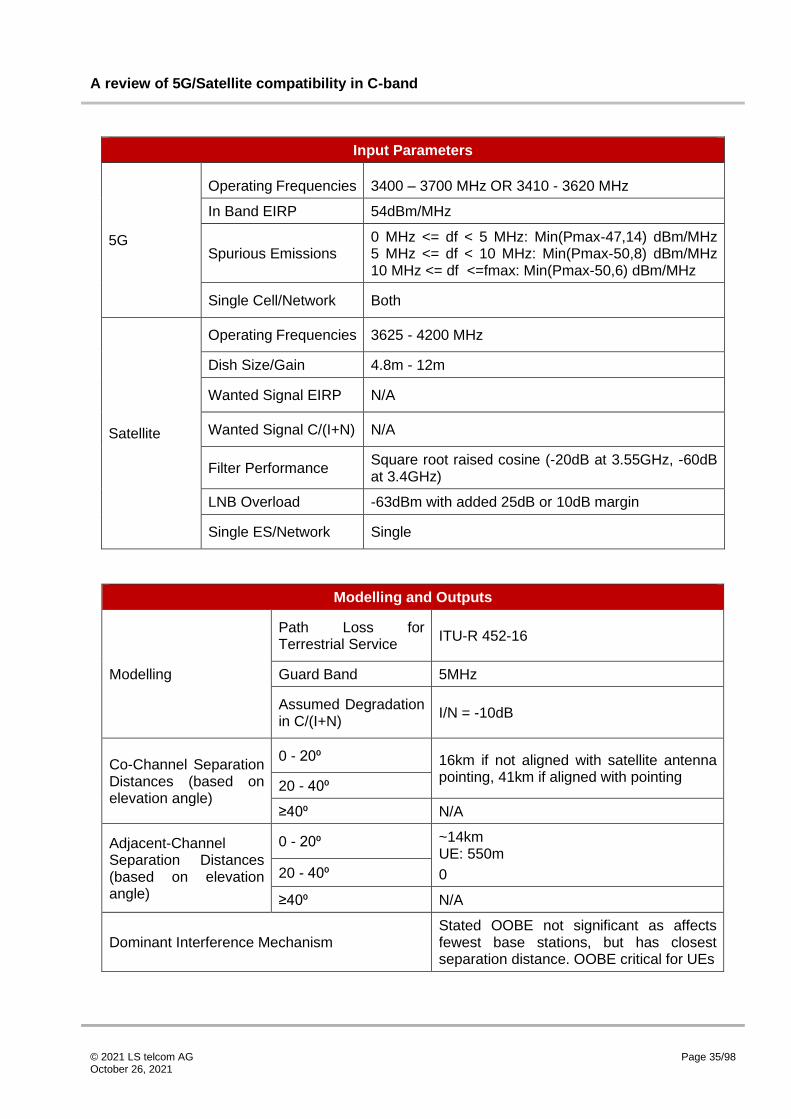
The assumed input and modelling parameters are shown below, alongside the resulting separation
distances.
A review of 5G/Satellite compatibility in C-band
© 2021 LS telcom AG October 26, 2021
Page 35/98
Input Parameters
5G
Operating Frequencies 3400 – 3700 MHz OR 3410 - 3620 MHz
In Band EIRP 54dBm/MHz
Spurious Emissions 0 MHz <= df < 5 MHz: Min(Pmax-47,14) dBm/MHz 5 MHz <= df < 10 MHz: Min(Pmax-50,8) dBm/MHz 10 MHz <= df <=fmax: Min(Pmax-50,6) dBm/MHz
Single Cell/Network Both
Satellite
Operating Frequencies 3625 - 4200 MHz
Dish Size/Gain 4.8m - 12m
Wanted Signal EIRP N/A
Wanted Signal C/(I+N) N/A
Filter Performance Square root raised cosine (-20dB at 3.55GHz, -60dB at 3.4GHz)
LNB Overload -63dBm with added 25dB or 10dB margin
Single ES/Network Single
Modelling and Outputs
Modelling
Path Loss for Terrestrial Service
ITU-R 452-16
Guard Band 5MHz
Assumed Degradation in C/(I+N)
I/N = -10dB
Co-Channel Separation Distances (based on elevation angle)
0 - 20⁰ 16km if not aligned with satellite antenna pointing, 41km if aligned with pointing 20 - 40⁰
≥40⁰ N/A
Adjacent-Channel Separation Distances (based on elevation angle)
0 - 20⁰ ~14km UE: 550m
0 20 - 40⁰
≥40⁰ N/A
Dominant Interference Mechanism Stated OOBE not significant as affects fewest base stations, but has closest separation distance. OOBE critical for UEs

A review of 5G/Satellite compatibility in C-band
© 2021 LS telcom AG October 26, 2021
Page 36/98
Subsequent references to this study will reference [3] and the chapter reference 6.2.1.
6.2.2 The Interference Mitigation Method and Field Test in C-Band Between 5G System and FSS Receiver
This study [4] was conducted by researchers at the China United Network Communications Group Co.
Ltd. and the Beijing University of Post and Telecommunications (BUPT) as an input to a project led by
the China Ministry of Industry and Information Technology (MIIT) on the feasibility of the co-existence
of 5G and FSS. The study took measurements of a real 17 base station 5G network, deployed by China
Unicom at BUPT, aiming to represent the worst case in which an FSS receiver was directly aligned with
a base station. Dish sizes of 1.8m and 3m, typical of TVRO installations within China, were used for the
satellite receive systems.
The performance of a number of LNB filters were verified under laboratory conditions, before the impact
on the levels at the satellite receiver of base station cell loading and the distance of the base station
from the satellite receiver were considered. In this way the isolation distance required to meet the LNB
saturation criteria is established. Next the impact of the relative angles of the base station transmit and
satellite receive antennas, and the aggregation of multiple cells, on receive levels were considered.
The assumed input and modelling parameters are shown below, alongside the resulting separation
distances. Note that the spurious emissions within the paper are quoted as 26dBm/MHz and
47dBm/MHz for 3650 – 3700 MHz and 3700 – 4200 MHz respectively. However, as this presents the
unlikely situation that the out of band emissions increase when moving further from the transmit band,
these are assumed to be -26dBm/MHz and -47dBm/MHz respectively. Note also that no specific
channel bandwidth has been provided, so an assumed channel bandwidth of 100MHz has been used
to calculate per MHz values.
Input Parameters
5G
Operating Frequencies 3500 - 3600MHz
In Band EIRP ~33dBm/MHz (total 53dBm)
Spurious Emissions 50 MHz <= df > 100MHz: -26dBm/MHz 100 MHz <= df < 600 MHz: -47dBm/MHz
Single Cell/Network Both
Satellite
Operating Frequencies 3700 - 4200 MHz OR 3625 - 4200 MHz
Dish Size/Gain 1.8m - 3m (aligned with BS)
Wanted Signal EIRP N/A
Wanted Signal C/(I+N) N/A
Filter Performance Minimum of -45dB in adjacent band
LNB Overload -60dBm
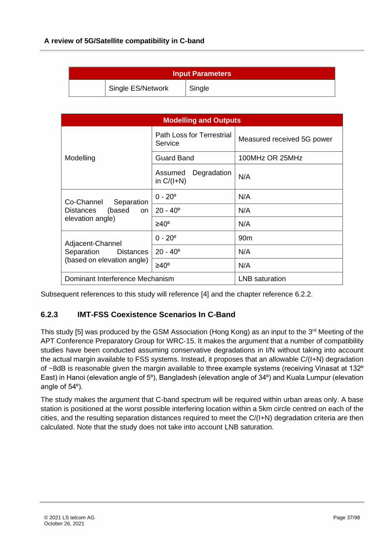
A review of 5G/Satellite compatibility in C-band
© 2021 LS telcom AG October 26, 2021
Page 37/98
Input Parameters
Single ES/Network Single
Modelling and Outputs
Modelling
Path Loss for Terrestrial Service
Measured received 5G power
Guard Band 100MHz OR 25MHz
Assumed Degradation in C/(I+N)
N/A
Co-Channel Separation Distances (based on elevation angle)
0 - 20⁰ N/A
20 - 40⁰ N/A
≥40⁰ N/A
Adjacent-Channel Separation Distances (based on elevation angle)
0 - 20⁰ 90m
20 - 40⁰ N/A
≥40⁰ N/A
Dominant Interference Mechanism LNB saturation
Subsequent references to this study will reference [4] and the chapter reference 6.2.2.
6.2.3 IMT-FSS Coexistence Scenarios In C-Band
This study [5] was produced by the GSM Association (Hong Kong) as an input to the 3rd Meeting of the
APT Conference Preparatory Group for WRC-15. It makes the argument that a number of compatibility
studies have been conducted assuming conservative degradations in I/N without taking into account
the actual margin available to FSS systems. Instead, it proposes that an allowable C/(I+N) degradation
of ~8dB is reasonable given the margin available to three example systems (receiving Vinasat at 132⁰
East) in Hanoi (elevation angle of 5⁰), Bangladesh (elevation angle of 34⁰) and Kuala Lumpur (elevation
angle of 54⁰).
The study makes the argument that C-band spectrum will be required within urban areas only. A base
station is positioned at the worst possible interfering location within a 5km circle centred on each of the
cities, and the resulting separation distances required to meet the C/(I+N) degradation criteria are then
calculated. Note that the study does not take into account LNB saturation.

A review of 5G/Satellite compatibility in C-band
© 2021 LS telcom AG October 26, 2021
Page 38/98
The assumed input and modelling parameters are shown below, alongside the resulting separation
distances.
Input Parameters
5G
Operating Frequencies 3400 - 3600 MHz
In Band EIRP 27dBm/MHz
Spurious Emissions N/A
Single Cell/Network Single
Satellite
Operating Frequencies 3400 - 3600 MHz
Dish Size/Gain 1.8m, 34.17dBi (peak)
Wanted Signal EIRP 47.7dBW
Wanted Signal C/(I+N) 17.01dB
Filter Performance N/A
LNB Overload N/A
Single ES/Network Single
Modelling and Outputs
Modelling
Path Loss for Terrestrial Service ITU R 452-15
Guard Band N/A
Assumed Degradation in C/(I+N) C/(I+N) = 8.69dB (reduction of ~8dB)
Co-Channel Separation Distances (based on elevation angle)
0 - 20⁰ Hanoi: 2.5km
20 - 40⁰ Bangladesh: 3.5km
≥40⁰ Kuala Lumpur: 2.5km
Adjacent-Channel Separation Distances (based on elevation angle)
0 - 20⁰ N/A
20 - 40⁰ N/A
≥40⁰ N/A
Dominant Interference Mechanism CCI
Subsequent references to this study will reference [5] and the chapter reference 6.2.3.

A review of 5G/Satellite compatibility in C-band
© 2021 LS telcom AG October 26, 2021
Page 39/98
6.2.4 Best Practices for Terrestrial-Satellite Coexistence during and after the C-Band Transition
This set of guidelines [6] was produced by TWG-1, a multi stakeholder group consisting of members
from a number of companies, both within the satellite and mobile industries. It sets out a number of
recommendations with regards to co-existence of IMT and FSS in C-band in the United States. The
report investigates a number of topics, including recommended separation distances (for both passive
and active antenna systems, with the distances quoted for active antenna systems protecting a given
proportion of 1,000 earth stations located randomly within 2.5km of the base station), recommended
filter performance, best practices for avoiding interference and best practices for mitigating interference
if observed. This section will focus on separation distances and filter performance.
The report considers the FCC mandated OOBE level of -13dBm/MHz and an equipment manufacturer
expected level of -40dBm/MHz, and produces a set of separation distances based on an allowable I/N
degradation of 6dB (with the associated PFD then adjusted downwards by 4dB). The assumed input
and modelling parameters are shown below, alongside the resulting separation distances.
Input Parameters
5G
Operating Frequencies 3700 - 3980 MHz
In Band EIRP 65dBm/MHz (rural) 62dBm/MHz (urban)
Spurious Emissions -13dBm/MHz -40dBm/MHz
Single Cell/Network Single
Satellite
Operating Frequencies 4000 - 4200 MHz
Dish Size/Gain N/A
Wanted Signal EIRP N/A
Wanted Signal C/(I+N) N/A
Filter Performance
0 MHz <= df < 15 MHz: 0dB 15 MHz <= df < 20 MHz: -30dB 20 MHz <= df < 100MHz: -60dB df > 100MHz: -70dB
LNB Overload -16dBW/m^2/MHz
Single ES/Network Single

A review of 5G/Satellite compatibility in C-band
© 2021 LS telcom AG October 26, 2021
Page 40/98
Modelling and Outputs
Modelling
Path Loss for Terrestrial Service
Free space and ITS Irregular Terrain Model
Guard Band 20MHz
Assumed Degradation in C/(I+N)
I/N=-6dB (adjusted down by 4dB)
Co-Channel Separation Distances (based on elevation angle)
0 - 20⁰ N/A
N/A
N/A
20 - 40⁰
≥40⁰
Adjacent-Channel Separation Distances (based on elevation angle)
0 - 20⁰ Passive Antenna: -13dBm/MHz: 26.6km (8.6-20.2km for ITS model) -40dBm/MHz: 1.2km
AAS: -13dBm/MHz: 0.2km (7%), 1.5-2km (49%), 5.5km (96%) -40dBm/MHz: <0.2km (7%), <0.2km (49%), <0.3km (96%)
LNB: Rural: 102m Urban: 73.2m
20 - 40⁰
≥40⁰
Dominant Interference Mechanism OOBE
Subsequent references to this study will reference [6] and the chapter reference 6.2.4.
6.2.5 Coexistence for LTE-Advanced and FSS Services in the 3.5GHz Band in Colombia
This study [7] was conducted by researchers at the Colombian School of Engineering and IMEC Ghent
University as an input to the Colombia National Spectrum Agency (ANE), a part of the Information,
Communication and Technology Ministry (MinTIC), investigation on the availability of new bands for the
deployment of 5G IMT services. It investigates the effect of guard band and elevation angle on the
required separation distance for co-channel and adjacent frequency IMT and FSS coexistence, based
on two known FSS receivers within Bogota, Columbia. IMT base stations are positioned along the axis
of each FSS receiver, at regular intervals, to represent a worst case.
The study determines the required separation distance between a single base station and a satellite
receiver (assuming an allowable degradation in I/N of 6.5dB), with a guard band of between -28 (i.e. an
overlap) and +25MHz and elevation angles of 11, 22 and 42⁰. The study finds that for any level of
overlap, the separation distance remained largely constant. Increasing the guard band however is found

A review of 5G/Satellite compatibility in C-band
© 2021 LS telcom AG October 26, 2021
Page 41/98
to decrease the required separation distance (per 5MHz of additional guard band, a reduction in
separation distance in the order of 25km for base stations and 100m for UEs).
The assumed input and modelling parameters are shown below, alongside the resulting separation
distances. Note that out of band emissions performance are not explicitly stated within the report. In
addition, it is unclear whether ITU-R 2001-2 or ITU-R 452-16 has been used for the propagation
modelling of IMT.
Input Parameters
5G
Operating Frequencies 3664 - 3718 MHz
In Band EIRP 48dBm/MHz Suburban 45dBm/MHz Urban 13dBm/MHz UE
Spurious Emissions N/A
Single Cell/Network Single
Satellite
Operating Frequencies 3718MHz
Dish Size/Gain -8.6dBi, -1.6dBi, 6.2dBi
Wanted Signal EIRP 90dBm6
Wanted Signal C/(I+N) N/A
Filter Performance N/A
LNB Overload N/A
Single ES/Network Single
Modelling and Outputs
Modelling
Path Loss for Terrestrial Service
ITU R 2001-2 OR ITU-R 452-16
Guard Band -28 to +25MHz
Assumed Degradation in C/(I+N)
I/N = -6.5dB
Co-Channel Separation Distances (based on elevation angle)
0 - 20⁰
Urban: 278km (BS) 2650m (UE)
Suburban: 244km (BS) 2125m (UE)
6 Note that SES-6 (the satellite assumed for the study) does not have an EIRP of 90dBm.

A review of 5G/Satellite compatibility in C-band
© 2021 LS telcom AG October 26, 2021
Page 42/98
Modelling and Outputs
20 - 40⁰
Urban: 215km (BS) 1000m (UE)
Suburban: 181km (BS) 875m (UE)
≥40⁰
Urban: 150km (BS) 750m (UE)
Suburban: 141km (BS) 655m (UE)
Adjacent-Channel Separation Distances (based on elevation angle)
0 - 20⁰
Urban: 210 - 88km (BS) 1000 - 380m (UE)
Suburban: 183 - 67km (BS) 975 - 500m (UE)
20 - 40⁰
Urban: 153 - 40km (BS) 650 - 200m (UE)
Suburban: 133 - 28km (BS) 500 - 465m (UE)
≥40⁰
Urban: 103 - 18km (BS) 480 - 200m (UE)
Suburban: 83 - 13km (BS) 500 - 265m (UE)
Dominant Interference Mechanism CCI/ACI
Subsequent references to this study will reference [7] and the chapter reference 6.2.5.
6.2.6 Coexistence Studies between LTE System and Earth Station of Fixed Satellite Service in the 3400-3600 MHz Frequency Bands in China
This study [8] was conducted by researchers at the Beijing University of Posts and
Telecommunications. It performs a deterministic analysis, based on ITU-R P.452-12, to determine
separation distances for co-channel and adjacent frequency operation of FSS and IMT (a single base
station and UE) with a range of guard bands and elevation angles typical for VSAT in China. The paper

A review of 5G/Satellite compatibility in C-band
© 2021 LS telcom AG October 26, 2021
Page 43/98
also investigates the effect to which angular separation helps attenuate incoming IMT signals when a
network is considered using Monte Carlo analysis.
The paper recommends that in the instance of China, based on an allowable degradation in I/N of 12dB,
a guard band of at least 10MHz should be sufficient to allow reasonable coexistence of IMT base
stations and FSS, and a guard band of at least 5MHz should be sufficient to allow reasonable
coexistence of IMT UE and FSS.
The assumed input and modelling parameters are shown below, alongside the resulting separation
distances. An FSS bandwidth of 60MHz has been assumed based on the receiver noise calculation.
Input Parameters
5G
Operating Frequencies 3400 - 3600 MHz
In Band EIRP 36dBm/MHz (BS) 14dBm/MHz (UE)
Spurious Emissions
BS 0MHz <= df < 5MHz: -4.65dBm/MHz 5MHz <= df <10 MHz: -11dBm/MHz 10MHz <= df: -11dBm/MHz UE 0MHz <= df < 1MHz: -2.7712dBm/MHz 1MHz <= df <5MHz: -16.02dBm/MHz 5MHz <= df <10MHz: -20dBm/MHz 10MHz <= df <15MHz: -32dBm/MHz 15MHz <= df: -84dBm/MHz
Single Cell/Network Both
Satellite
Operating Frequencies 3400 - 3600 MHz
Dish Size/Gain 4m
Wanted Signal EIRP N/A
Wanted Signal C/(I+N) N/A
Filter Performance N/A
LNB Overload -60dBm
Single ES/Network Single
Modelling and Outputs
Modelling
Path Loss for Terrestrial Service
ITU R 452-12
Guard Band 0MHz - 15MHz
Assumed Degradation in C/(I+N)
I/N = -12.2dB

A review of 5G/Satellite compatibility in C-band
© 2021 LS telcom AG October 26, 2021
Page 44/98
Modelling and Outputs
Co-Channel Separation Distances (based on elevation angle)
0 - 20⁰ BS: 200km UE: 5km
20 - 40⁰
≥40⁰
Adjacent-Channel Separation Distances (based on elevation angle)
0 - 20⁰ 0MHz GB BS: 4.5km UE: 450m
5-10MHz GB BS: 2km UE: 100m
>10MHz GB BS: 800m LNB: 500m
20 - 40⁰
≥40⁰
Dominant Interference Mechanism CCI/ACI
Subsequent references to this study will reference [8] and the chapter reference 6.2.6.
6.2.7 Coexistence conditions of LTE-advanced at 3400–3600 MHz with TVRO at 3625–4200 MHz in Brazil
This study [9] was conducted by authors at the National Telecommunications Agency, Anatel, in Brazil.
It defines operational constraints for LTE-A and FSS based on the protection of LNB (to -45dBm or -
60dBm) within typical TVRO (TV receive only) installations in Brazil, using Monte Carlo simulations
performed within SEAMCAT (Spectrum Engineering Advanced Monte Carlo Analysis Tool).
The study assumes a typical antenna diameter of 1.5m (32dBi peak gain), but with a number of different
off axis gains corresponding to various elevation angles: 0dBi (19⁰), -4dBi (28⁰) and -10dBi (48⁰). It
makes use of free space path loss close to the transmitting base station, before linearly interpolating to
ITU-R 452-16 at greater distances. OOBE emissions are stated to be as 3GPP TS 36.104 v13.2.0 for
base stations, and 3GPP TS 36.101 v14.0.0 for UEs, although the values taken for the analysis are not
explicitly stated. The separation distances are given for each type of base station.
The assumed input and modelling parameters are shown below, alongside the resulting separation
distances.
Input Parameters
5G
Operating Frequencies 3400 - 3600 MHz
In Band EIRP
Suburban Macro: 34, 40, 45dBm/MHz Urban Macro: 27, 39, 45dBm/MHz

A review of 5G/Satellite compatibility in C-band
© 2021 LS telcom AG October 26, 2021
Page 45/98
Input Parameters
Urban Small: 16, 24dBm/MHz
Spurious Emissions BS: 3GPP TS 36.104 v13.2.0
UE: 3GPP TS 36.101 v14.0.0
Single Cell/Network Both
Satellite
Operating Frequencies 3625 - 4200 MHz
Dish Size/Gain 0dBi, -4dBi, -10dBi (32dBi peak gain)
Wanted Signal EIRP N/A
Wanted Signal C/(I+N) N/A
Filter Performance N/A
LNB Overload -60dBm, -45dBm
Single ES/Network TVRO
Modelling and Outputs
Modelling
Path Loss for Terrestrial Service
ITU R 452-16 (using free space for short distances, 452 for long distances, and linear interpolation between the two for mid range)
Guard Band 25MHz
Assumed Degradation in C/(I+N)
N/A
Co-Channel Separation Distances (based on elevation angle)
0 - 20⁰ N/A
20 - 40⁰ N/A
≥40⁰ N/A
Adjacent-Channel Separation Distances (based on elevation angle)
0 - 20⁰
-60dBm LNB: Suburban Macro: not possible Urban Macro: not possible Urban Small: 80-70m -45dBm LNB Suburban Macro: 430-230m Urban Macro: 120-60m Urban Small: 50-30m
20 - 40⁰
-60dBm LNB: Suburban Macro: not possible Urban Macro: not possible Urban Small: 70m

A review of 5G/Satellite compatibility in C-band
© 2021 LS telcom AG October 26, 2021
Page 46/98
Modelling and Outputs
-45dBm LNB Suburban Macro: 245-110m Urban Macro: 90-10m Urban Small: 40-15m
≥40⁰
-60dBm LNB: Suburban Macro: not possible Urban Macro: 270-95m Urban Small: 60-50m -45dBm LNB Suburban Macro: 75-10m Urban Macro: 55-10m Urban Small: 20-10m
Dominant Interference Mechanism LNB saturation
Subsequent references to this study will reference [9] and the chapter reference 6.2.7.
6.2.8 Interference Mitigation Technique for the Sharing between IMT-Advanced and Fixed Satellite Service
This study [10] was conducted by researchers at the Radio Research Laboratory (Ministry of
Information and Communication, Korea), Yonsei University and Myongji College. It considers the
potential for interference reduction at an FSS receiver by means of creating nulls in the IMT transmit
antenna pattern. A theoretical model of the technique is considered and validated, and the technique’s
impact on the separation distances (for both co-channel and adjacent frequency scenarios with a range
of guard bands) required to meet an I/N degradation of 12.2dB are considered. Lastly to account for
the theoretical nature of the approach, the impact of errors on the separation distances is considered
also.
The study finds large reductions in separation distances by using the technique (>99% for the co-
channel case and >92% for the adjacent frequency case, dependent on the guard band used), although
this is found to be highly dependent on the extent of the error. Note also that the out of band emissions
performance used within the study is not stated.
The assumed input and modelling parameters are shown below, alongside the resulting separation
distances.
Input Parameters
5G
Operating Frequencies 4000MHz
In Band EIRP 26dBm/MHz
Spurious Emissions N/A
Single Cell/Network Single

A review of 5G/Satellite compatibility in C-band
© 2021 LS telcom AG October 26, 2021
Page 47/98
Input Parameters
Satellite
Operating Frequencies 4000MHz
Dish Size/Gain 3.8m
Wanted Signal EIRP N/A
Wanted Signal C/(I+N) N/A
Filter Performance N/A
LNB Overload N/A
Single ES/Network Single
Modelling and Outputs
Modelling
Path Loss for Terrestrial Service
ITU 452-12
Guard Band -9 to 9MHz
Assumed Degradation in C/(I+N)
I/N=-12.2dB
Co-Channel Separation Distances (based on elevation angle)
0 - 20⁰ W/o Mitigation: 44km W Mitigation: 35m (no error) 7km (2 deg error) 27km (10 deg error)
20 - 40⁰
≥40⁰
Adjacent-Channel Separation Distances (based on elevation angle)
0 - 20⁰ Without mitigation: 17-0.13km With mitigation:<10m (no error) 5.56km-20m (5deg error) 9.84km-30m (10deg error)
20 - 40⁰
≥40⁰
Dominant Interference Mechanism CCI/ACI
Subsequent references to this study will reference [10] and the chapter reference 6.2.8.
6.2.9 Geographic Sharing in C-band
This study [11] was conducted by Transfinite Systems on behalf of Ofcom (UK). The study considers
the possibility for FSS and fixed links within the UK to share spectrum with IMT, looking to determine
which areas have sufficiently few earth stations or fixed links to facilitate sharing. In addition, the study
conducts interference zone analysis for specific example FSS and fixed link systems based on an
allowable I/N of -10dB. This report will focus on the interference zone analysis results.
The report considers just co-channel operation of the two systems and compares the impact of generic
flat Earth modelling and the inclusion of terrain, clutter and polarisation discrimination on the resulting
separation distances. The report finds that for an example station at Chalfont Grove in London (with

A review of 5G/Satellite compatibility in C-band
© 2021 LS telcom AG October 26, 2021
Page 48/98
elevation angles 8⁰ and 11⁰), the required separation distances are anything between 24 and 70km,
dependent on the assumptions taken.
The assumed input and modelling parameters are shown below, alongside the resulting separation
distances.
Input Parameters
5G
Operating Frequencies 3800 - 4200 MHz
In Band EIRP 19dBm/MHz (outdoor)
14dBm/MHz (indoor)
Spurious Emissions 0MHz <= df < 5MHz: 0dB 5 MHz <= df: -45dB
Single Cell/Network Single
Satellite
Operating Frequencies 3800 - 4200 MHz
Dish Size/Gain 55dBi
Wanted Signal EIRP N/A
Wanted Signal C/(I+N) N/A
Filter Performance Gaussian, -30dB at 2 x transponder bandwidth
LNB Overload N/A
Single ES/Network Single
Modelling and Outputs
Modelling
Path Loss for Terrestrial Service
ITU 452-15
Guard Band N/A
Assumed Degradation in C/(I+N)
I/N = -10dB
Co-Channel Separation Distances (based on elevation angle)
0 - 20⁰
Chalfont Outdoor BS: 25km (1. flat Earth) 73km (2. terrain, but no clutter) 70km (3. as 2, with clutter) 25km (4. as 3, with extra dense urban clutter loss) 24km (5. as 4, with polarisation discrimination, traffic considerations)
3km (indoor BS)
20 - 40⁰ N/A
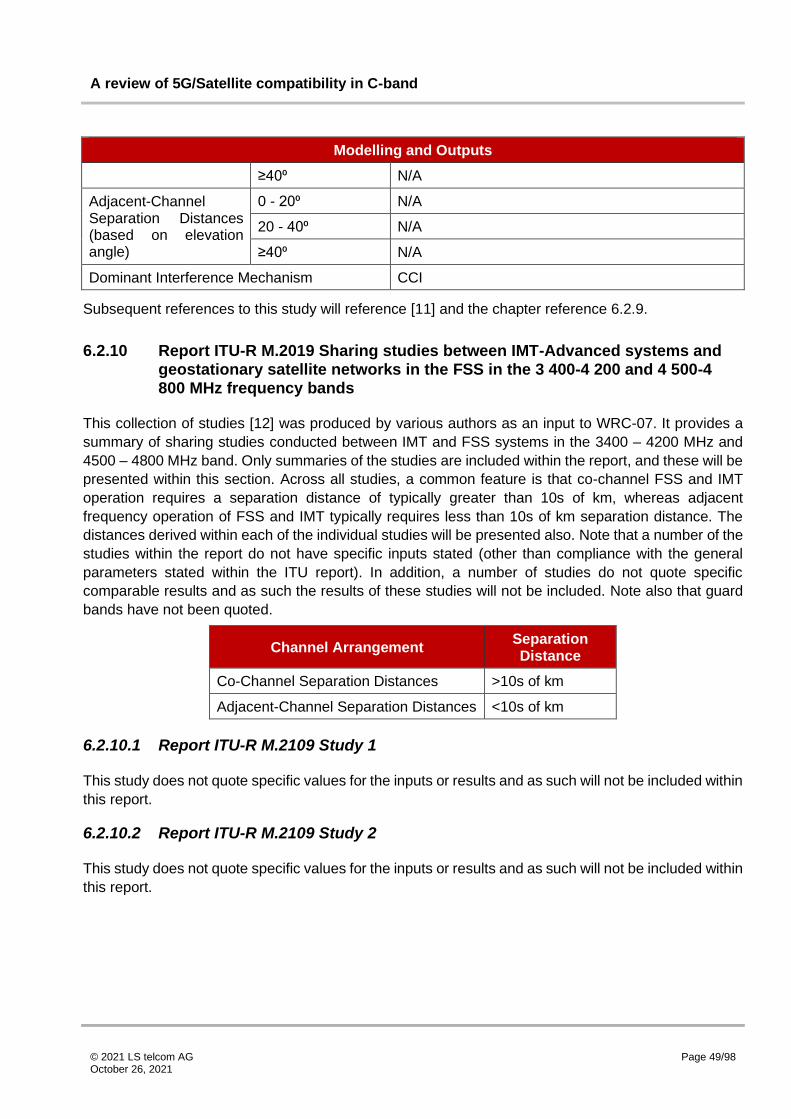
A review of 5G/Satellite compatibility in C-band
© 2021 LS telcom AG October 26, 2021
Page 49/98
Modelling and Outputs
≥40⁰ N/A
Adjacent-Channel Separation Distances (based on elevation angle)
0 - 20⁰ N/A
20 - 40⁰ N/A
≥40⁰ N/A
Dominant Interference Mechanism CCI
Subsequent references to this study will reference [11] and the chapter reference 6.2.9.
6.2.10 Report ITU-R M.2019 Sharing studies between IMT-Advanced systems and geostationary satellite networks in the FSS in the 3 400-4 200 and 4 500-4 800 MHz frequency bands
This collection of studies [12] was produced by various authors as an input to WRC-07. It provides a
summary of sharing studies conducted between IMT and FSS systems in the 3400 – 4200 MHz and
4500 – 4800 MHz band. Only summaries of the studies are included within the report, and these will be
presented within this section. Across all studies, a common feature is that co-channel FSS and IMT
operation requires a separation distance of typically greater than 10s of km, whereas adjacent
frequency operation of FSS and IMT typically requires less than 10s of km separation distance. The
distances derived within each of the individual studies will be presented also. Note that a number of the
studies within the report do not have specific inputs stated (other than compliance with the general
parameters stated within the ITU report). In addition, a number of studies do not quote specific
comparable results and as such the results of these studies will not be included. Note also that guard
bands have not been quoted.
Channel Arrangement Separation Distance
Co-Channel Separation Distances >10s of km
Adjacent-Channel Separation Distances <10s of km
6.2.10.1 Report ITU-R M.2109 Study 1
This study does not quote specific values for the inputs or results and as such will not be included within
this report.
6.2.10.2 Report ITU-R M.2109 Study 2
This study does not quote specific values for the inputs or results and as such will not be included within
this report.
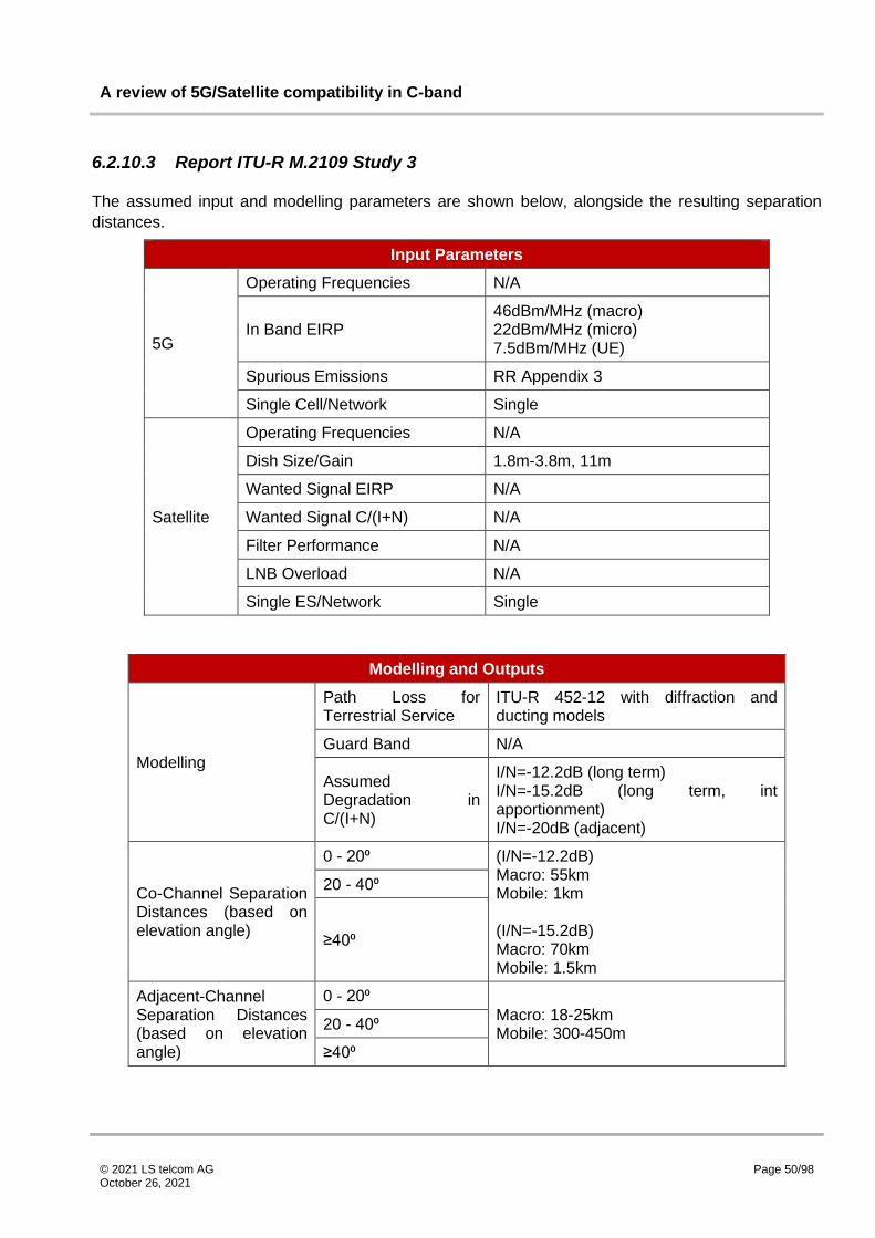
A review of 5G/Satellite compatibility in C-band
© 2021 LS telcom AG October 26, 2021
Page 50/98
6.2.10.3 Report ITU-R M.2109 Study 3
The assumed input and modelling parameters are shown below, alongside the resulting separation
distances.
Input Parameters
5G
Operating Frequencies N/A
In Band EIRP 46dBm/MHz (macro) 22dBm/MHz (micro) 7.5dBm/MHz (UE)
Spurious Emissions RR Appendix 3
Single Cell/Network Single
Satellite
Operating Frequencies N/A
Dish Size/Gain 1.8m-3.8m, 11m
Wanted Signal EIRP N/A
Wanted Signal C/(I+N) N/A
Filter Performance N/A
LNB Overload N/A
Single ES/Network Single
Modelling and Outputs
Modelling
Path Loss for Terrestrial Service
ITU-R 452-12 with diffraction and ducting models
Guard Band N/A
Assumed Degradation in C/(I+N)
I/N=-12.2dB (long term) I/N=-15.2dB (long term, int apportionment) I/N=-20dB (adjacent)
Co-Channel Separation Distances (based on elevation angle)
0 - 20⁰ (I/N=-12.2dB) Macro: 55km Mobile: 1km (I/N=-15.2dB) Macro: 70km Mobile: 1.5km
20 - 40⁰
≥40⁰
Adjacent-Channel Separation Distances (based on elevation angle)
0 - 20⁰ Macro: 18-25km Mobile: 300-450m
20 - 40⁰
≥40⁰

A review of 5G/Satellite compatibility in C-band
© 2021 LS telcom AG October 26, 2021
Page 51/98
Modelling and Outputs
Dominant Interference Mechanism CCI/ACI
Subsequent references to this study will reference [12] and the chapter reference 6.2.10.3.
6.2.10.4 Report ITU-R M.2109 Study 4
The assumed input and modelling parameters are shown below, alongside the resulting separation
distances.
Input Parameters
5G
Operating Frequencies N/A
In Band EIRP 46dBm/MHz (macro) 22dBm/MHz (micro) 7.5dBm/MHz (UE)
Spurious Emissions 1st Adj: -45dB 2nd Adj: -50dB 3rd Adj +:-66dB
Single Cell/Network Single
Satellite
Operating Frequencies N/A
Dish Size/Gain 2.4m
Wanted Signal EIRP N/A
Wanted Signal C/(I+N) N/A
Filter Performance N/A
LNB Overload N/A
Single ES/Network Single
Modelling and Outputs
Modelling
Path Loss for Terrestrial Service
ITU 452-12, LoS with sub-path diffraction
Guard Band N/A
Assumed Degradation in C/(I+N)
I/N=-12.2dB (long term) I/N=-20dB (adjacent)
Co-Channel Separation Distances (based on elevation angle)
0 - 20⁰ Macro Urban: 37-54km Micro Urban: 15-23km Macro rural: 40-59km
20 - 40⁰
≥40⁰

A review of 5G/Satellite compatibility in C-band
© 2021 LS telcom AG October 26, 2021
Page 52/98
Modelling and Outputs
Adjacent-Channel Separation Distances (based on elevation angle)
0 - 20⁰ N/A
N/A
N/A
20 - 40⁰
≥40⁰
Dominant Interference Mechanism CCI
Subsequent references to this study will reference [12] and the chapter reference 6.2.10.4.
6.2.10.5 Report ITU-R M.2109 Study 5
The assumed input and modelling parameters are shown below, alongside the resulting separation
distances.
Input Parameters
5G
Operating Frequencies N/A
In Band EIRP 46dBm/MHz (macro) 22dBm/MHz (micro) 7.5dBm/MHz (UE)
Spurious Emissions 1st Adj: -45dB 2nd Adj: -50dB 3rd Adj +:-66dB
Single Cell/Network Both
Satellite
Operating Frequencies N/A
Dish Size/Gain 1.8m-3.8m, 11m
Wanted Signal EIRP N/A
Wanted Signal C/(I+N) N/A
Filter Performance N/A
LNB Overload N/A
Single ES/Network Single
Modelling and Outputs
Modelling
Path Loss for Terrestrial Service
ITU 452-12
Guard Band N/A
Assumed Degradation in C/(I+N)
I/N=-12.2dB (long term) I/N=-20dB (adjacent)

A review of 5G/Satellite compatibility in C-band
© 2021 LS telcom AG October 26, 2021
Page 53/98
Modelling and Outputs
Co-Channel Separation Distances (based on elevation angle)
0 - 20⁰ Single Entry: Base Station: 45-58km (5-48 deg)
Aggregate: Base Station: 51-60km (5-48deg)
Mobile Station: 0.5-1.5km
20 - 40⁰
≥40⁰
Adjacent-Channel Separation Distances (based on elevation angle)
0 - 20⁰ Single Entry: CMDA: 10-34km OFDMA: 0.07-19km
Aggregate: CDMA Macro: 15-37km OFDMA Macro: 0.35-21km
20 - 40⁰
≥40⁰
Dominant Interference Mechanism CCI/ACI
Subsequent references to this study will reference [12] and the chapter reference 6.2.10.5.
6.2.10.6 Report ITU-R M.2109 Study 6
The assumed input and modelling parameters are shown below, alongside the resulting separation
distances.
Input Parameters
5G
Operating Frequencies N/A
In Band EIRP 46dBm/MHz (macro) 22dBm/MHz (micro) 7.5dBm/MHz (UE)
Spurious Emissions 1st Adj: -45dB 2nd Adj: -50dB 3rd Adj +:-66dB
Single Cell/Network Single
Satellite
Operating Frequencies N/A
Dish Size/Gain 1.8m-3.8m, 11m
Wanted Signal EIRP N/A
Wanted Signal C/(I+N) N/A
Filter Performance N/A
LNB Overload N/A
Single ES/Network Single
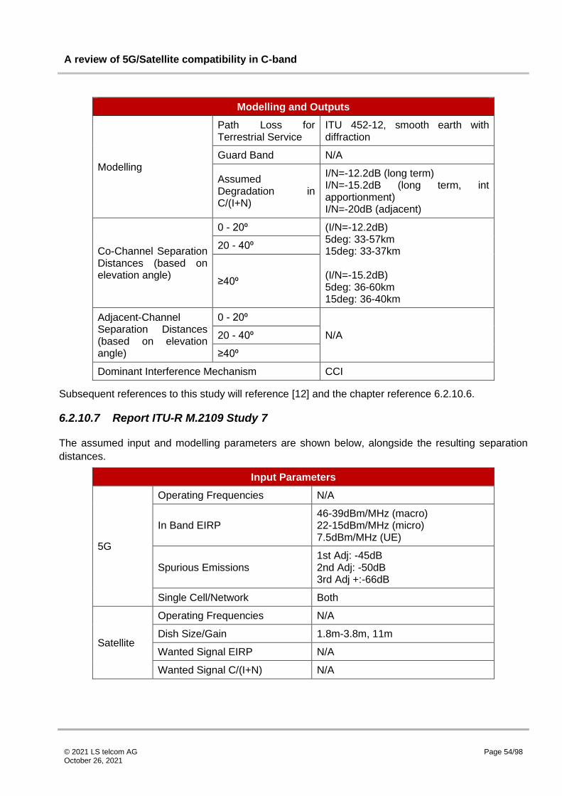
A review of 5G/Satellite compatibility in C-band
© 2021 LS telcom AG October 26, 2021
Page 54/98
Modelling and Outputs
Modelling
Path Loss for Terrestrial Service
ITU 452-12, smooth earth with diffraction
Guard Band N/A
Assumed Degradation in C/(I+N)
I/N=-12.2dB (long term) I/N=-15.2dB (long term, int apportionment) I/N=-20dB (adjacent)
Co-Channel Separation Distances (based on elevation angle)
0 - 20⁰ (I/N=-12.2dB) 5deg: 33-57km 15deg: 33-37km (I/N=-15.2dB) 5deg: 36-60km 15deg: 36-40km
20 - 40⁰
≥40⁰
Adjacent-Channel Separation Distances (based on elevation angle)
0 - 20⁰
N/A 20 - 40⁰
≥40⁰
Dominant Interference Mechanism CCI
Subsequent references to this study will reference [12] and the chapter reference 6.2.10.6.
6.2.10.7 Report ITU-R M.2109 Study 7
The assumed input and modelling parameters are shown below, alongside the resulting separation
distances.
Input Parameters
5G
Operating Frequencies N/A
In Band EIRP 46-39dBm/MHz (macro) 22-15dBm/MHz (micro) 7.5dBm/MHz (UE)
Spurious Emissions 1st Adj: -45dB 2nd Adj: -50dB 3rd Adj +:-66dB
Single Cell/Network Both
Satellite
Operating Frequencies N/A
Dish Size/Gain 1.8m-3.8m, 11m
Wanted Signal EIRP N/A
Wanted Signal C/(I+N) N/A

A review of 5G/Satellite compatibility in C-band
© 2021 LS telcom AG October 26, 2021
Page 55/98
Input Parameters
Filter Performance N/A
LNB Overload N/A
Single ES/Network Single
Modelling and Outputs
Modelling
Path Loss for Terrestrial Service
ITU 452-12
Guard Band N/A
Assumed Degradation in C/(I+N)
I/N=-12.2dB (long term)
I/N=-20dB (adjacent)
Co-Channel Separation Distances (based on elevation angle)
0 - 20⁰ Single Entry: CDMA Macro: 47-65.6km CDMA Micro: 39-49.5km CDMA Mobile: 0km OFDMA Macro: 43-55km OFDMA Micro: 29-47km OFDMA Mobile: 0km
Aggregate: CDMA Macro: 56-87km CDMA Micro: 49-58km CDMA Mobile: 0km OFDMA Macro: 51-61km OFDMA Micro: 46-53km OFDMA Mobile: 0km
20 - 40⁰
≥40⁰
Adjacent-Channel Separation Distances (based on elevation angle)
0 - 20⁰ Single Entry: CDMA Macro: 10-42.5km CDMA Micro: 2-14km OFDMA Macro: 5-29km OFDMA Micro: 2.4-8.7km
Aggregate: CDMA Macro: 27-45.5km CDMA Micro: 11-35km OFDMA Macro: 15-41km OFDMA Micro: 4-8.5km OFDMA Mobile: 0km
20 - 40⁰
≥40⁰
Dominant Interference Mechanism CCI/ACI
Subsequent references to this study will reference [12] and the chapter reference 6.2.10.7.

A review of 5G/Satellite compatibility in C-band
© 2021 LS telcom AG October 26, 2021
Page 56/98
6.2.10.8 Report ITU-R M.2109 Study 8
This study does not quote specific values for the inputs or results and as such will not be included within
this report.
6.2.10.9 Report ITU-R M.2109 Study 9
The assumed input and modelling parameters are shown below, alongside the resulting separation
distances.
Input Parameters
5G
Operating Frequencies N/A
In Band EIRP 46dBm/MHz (macro) 22dBm/MHz (micro) 7.5dBm/MHz (UE)
Spurious Emissions 3GPP TS 25.104 V7.5.0
Single Cell/Network Single
Satellite
Operating Frequencies N/A
Dish Size/Gain 1.8m-3.8m, 11m
Wanted Signal EIRP N/A
Wanted Signal C/(I+N) N/A
Filter Performance N/A
LNB Overload -60dBm
Single ES/Network Single
Modelling and Outputs
Modelling
Path Loss for Terrestrial Service
ITU 452-12, LoS w/o sub-path diffraction, multipath or focussing effects
Guard Band N/A
Assumed Degradation in C/(I+N)
I/N=-12.2dB (long term) I/N=-20dB (adjacent)
Co-Channel Separation Distances (based on elevation angle)
0 - 20⁰ N/A
20 - 40⁰ N/A
≥40⁰ N/A

A review of 5G/Satellite compatibility in C-band
© 2021 LS telcom AG October 26, 2021
Page 57/98
Modelling and Outputs
Adjacent-Channel Separation Distances (based on elevation angle)
0 - 20⁰ Macro: 49.5-80km Micro: 39.5-51km UE: 25-32.5km
LNB Saturation: Mobile station: 170m Micro: 600m Macro: 9.5km
20 - 40⁰
≥40⁰
Dominant Interference Mechanism LNB saturation
Subsequent references to this study will reference [12] and the chapter reference 6.2.10.9
6.2.10.10 Report ITU-R M.2109 Study 10
This study does not quote specific values for the inputs or results and as such will not be included within
this report.
6.2.10.11 Report ITU-R M.2109 Study 11
This study does not quote specific values for the inputs or results and as such will not be included within
this report.
6.2.11 Report ITU-R S.2368-0 Sharing studies between IMT-Advanced systems and geostationary satellite networks in the FSS in the 3 400-4 200 MHz and 4 500-4 800 MHz frequency bands in the WRC study cycle leading to WRC-15
This collection of studies [13] was produced by a number of authors as an input to WRC-15. It provides
a summary of sharing studies conducted between IMT and FSS systems in the 3400 – 4200 MHz and
4500 – 4800 MHz band. Results from each of the studies will be presented individually, but typical
findings regarding co-channel and adjacent frequency separation distances are shown below. Values
for long term interference (typically co-channel I/N of -10dB and adjacent frequency I/N of -20dB
consistent with ITU-R S.1432) and short term interference (I/N of -1.3dB) are presented. In some cases,
separation distances based on an aggregate interference are presented also. Note that some studies
do make use of slightly different I/N criteria which will be reflected in the summary tables.
Channel Arrangement Separation Distance
Co-Channel Separation Distances
CCI Macro cell: 10s of km/100s of km (long term/short term int) Small cell: 10s of km Small Indoor: 5 to 10s of km

A review of 5G/Satellite compatibility in C-band
© 2021 LS telcom AG October 26, 2021
Page 58/98
Channel Arrangement Separation Distance
Adjacent-Channel Separation Distances
AC Macro cell: 5 to 10s of km Small cell: 900m to 5km
LNB/LNA Overdrive Macro cell: 4km to 9km Small cell: 100m to 900m
Intermods Macro cell: 2km to 8km Small cell: 100m to 500m
The report also investigates a small number of real interference cases into FSS receivers within the
band, including from WiMAX stations in Bangladesh and BWA in Brazil.
6.2.11.1 Report ITU-R S.2368-0 Study 1
This study considers non-site specific conditions through use of a smooth Earth model to determine
maximum co-channel separation distances for IMT and FSS. The study considers a number of
scenarios in which clutter is either not included, included at just the IMT end of the link, or at both the
IMT and FSS ends of the link. Note that the results quoted here reflect the values associated with clutter
at both ends of the link for the long term interference criterion. Additional separation distances are
quoted also for the case where attenuation of the interfering IMT is higher than initially assumed,
although these are not included in this report.
The assumed input and modelling parameters are shown below, alongside the resulting separation
distances.
Input Parameters
5G
Operating Frequencies 3400 - 4200 MHz
In Band EIRP
48dBm/MHz (Macro Urban & Suburban) 16dBm/MHz (Small Outdoor) 11dBm/MHz (Small Indoor)
Spurious Emissions N/A
Single Cell/Network Single
Satellite
Operating Frequencies 3400 - 4200 MHz
Dish Size/Gain 2.4m, 16m
Wanted Signal EIRP N/A
Wanted Signal C/(I+N) N/A
Filter Performance N/A
LNB Overload N/A
Single ES/Network Single

A review of 5G/Satellite compatibility in C-band
© 2021 LS telcom AG October 26, 2021
Page 59/98
Modelling and Outputs
Modelling
Path Loss for Terrestrial Service
ITU 452-14, smooth Earth
Guard Band N/A
Assumed Degradation in C/(I+N)
I/N = -13dB (long term) I/N = -1.3dB (short term, single entry)
Co-Channel Separation Distances (based on elevation angle)
0 - 20⁰
Long Term: Macro Sub: 61-63km Macro Urban: 46-48km Small Outdoor: 25km Small Indoor: <5km
20 - 40⁰ N/A
≥40⁰
Long Term: Macro Sub: 35-36km Macro Urban: 20-22km Small Outdoor: 6km Small Indoor: <5km
Adjacent-Channel Separation Distances (based on elevation angle)
0 - 20⁰
N/A 20 - 40⁰
≥40⁰
Dominant Interference Mechanism CCI
Subsequent references to this study will reference [13] and the chapter reference 6.2.11.1.
6.2.11.2 Report ITU-R S.2368-0 Study 2
This study investigates the impact of a network of IMT base stations, both outdoor and indoor, on the
required separation distances for IMT FSS coexistence within both a co-channel and adjacent
frequency band plan. This study assumes a non-site specific scenario, making use of Monte Carlo
analysis, with representative terrain and clutter. Deterministic analysis is conducted also, although this
isn’t presented here. Note that the values quoted here are for the long term interference criterion. The
study assumes elevation angles of 5, 15 and 48⁰.
The assumed input and modelling parameters are shown below, alongside the resulting separation
distances.

A review of 5G/Satellite compatibility in C-band
© 2021 LS telcom AG October 26, 2021
Page 60/98
Input Parameters
5G
Operating Frequencies N/A
In Band EIRP
3dB Less for Aggregate Simulation: 48dBm/MHz (Suburban Macro) 33dBm/MHz (Urban Macro) 16dBm/MHz (Outdoor Small) 11dBm/MHz (Indoor Small)
Spurious Emissions 3GPP 36.104 v.11.2.0
Single Cell/Network Network
Satellite
Operating Frequencies N/A
Dish Size/Gain 2.4m, 10m
Wanted Signal EIRP N/A
Wanted Signal C/(I+N) N/A
Filter Performance N/A
LNB Overload -55dBm
Single ES/Network Single
Modelling and Outputs
Modelling
Path Loss for Terrestrial Service
ITU 452-14
Guard Band 0, 5, 10MHz
Assumed Degradation in C/(I+N)
I/N = -13dB (long term) I/N = -1.3dB (short term, single entry) I/N = -20dB (aggregate, ACI)
Co-Channel Separation Distances (based on elevation angle)
0 - 20⁰
Long Term: Macro Sub: 60.5km Macro Urb: 72km Small Outdoor: 5km Small Indoor: 4-5km
20 - 40⁰
Long Term (15 deg): Macro Sub: 58.2km Macro Urb: 69km Small Outdoor: 1.2km Small Indoor: 1-3km

A review of 5G/Satellite compatibility in C-band
© 2021 LS telcom AG October 26, 2021
Page 61/98
Modelling and Outputs
≥40⁰
Long Term: Macro Sub: 55.6km Macro Urb: 67km Small Outdoor: 0.53km Small Indoor: 0.55-1.5km
Adjacent-Channel Separation Distances (based on elevation angle)
0 - 20⁰
0MHz GB: Macro Sub: 1.4km Macro Urb: 49km Small Outdoor: <0.3km Small Indoor: <0.4km
5MHz GB: Macro Sub: 1.3km Macro Urb: 49km
10MHz GB: Macro Sub: 1.3km Macro Urb: 49km
20 - 40⁰
0MHz GB (15 deg): Macro Sub: <0.06km Macro Urb: 43.5km Small Outdoor: <0.3km Small Indoor: <0.4km
5MHz GB:Macro Sub: <0.06km Macro Urb: 43km
10MHz GB: Macro Sub: <0.06km Macro Urb: 43km
≥40⁰
0MHz GB: Macro Sub: <0.06km Macro Urb: 39km Small Outdoor: <0.3km Small Indoor: <0.4km
5MHz GB: Macro Sub: <0.06km Macro Urb: 39km
10MHz GB: Macro Sub: <0.06km Macro Urb: 38.5km
Dominant Interference Mechanism CCI/ACI
Subsequent references to this study will reference [13] and the chapter reference 6.2.11.2.

A review of 5G/Satellite compatibility in C-band
© 2021 LS telcom AG October 26, 2021
Page 62/98
6.2.11.3 Report ITU-R S.2368-0 Study 3
This study considers a specific FSS earth station in Yamaguchi prefecture, Japan, with elevation angles
of 6.5 and 36⁰. It investigates the effect of terrain on the separation distances required for co-channel
and adjacent frequency coexistence of FSS and IMT. Whilst separation distances are not explicitly
quoted, they are presented on maps, and values read from these are presented within this section. In
addition, the effect of base station deployments within a number of cities around the FSS earth station
on LNB saturation is considered also, although no separation distance is quoted in this case. Note that
no guard band is stated within the adjacent frequency analysis part of the study.
The assumed input and modelling parameters are shown below, alongside the resulting separation
distances.
Input Parameters
5G
Operating Frequencies 3400 - 3600 MHz
In Band EIRP 33dBm/MHz (Macro Suburban) 17dBm/MHz (Small Outdoor)
Spurious Emissions TS 36.104 v.11.2.0
Single Cell/Network Single
Satellite
Operating Frequencies 3400 - 4200 MHz
Dish Size/Gain 18m
Wanted Signal EIRP N/A
Wanted Signal C/(I+N) N/A
Filter Performance N/A
LNB Overload -50 to -60dBm
Single ES/Network Single
Modelling and Outputs
Modelling
Path Loss for Terrestrial Service
ITU 452-14
Guard Band N/A
Assumed Degradation in C/(I+N)
I/N=-10dB (long term) I/N=-1.3dB (short term)
Co-Channel Separation Distances (based on elevation angle)
0 - 20⁰ Macro suburban: 30-40km Small Outdoor: 15-25km
20 - 40⁰ Macro suburban: 10-20km Small Outdoor: 15-25km
≥40⁰ N/A

A review of 5G/Satellite compatibility in C-band
© 2021 LS telcom AG October 26, 2021
Page 63/98
Modelling and Outputs
Adjacent-Channel Separation Distances (based on elevation angle)
0 - 20⁰ Macro suburban: ~15km Small Outdoor: ~10km
20 - 40⁰ Macro suburban: ~15km Small Outdoor: ~5km
≥40⁰ N/A
Dominant Interference Mechanism CCI/ACI
Subsequent references to this study will reference [13] and the chapter reference 6.2.11.3.
6.2.11.4 Report ITU-R S.2368-0 Study 4
This study investigates the required separation distances for both co-channel and adjacent frequency
co-existence of IMT and FSS, based on a representative terrain profile. No guard band was assumed
within the study for adjacent frequency analysis. For the single base station analysis, the IMT base
station is assumed to move along the representative terrain profile until the protection criteria for the
FSS receiver is breached. For the network analysis, a network of base stations is positioned around
the FSS receiver, with the protection distance increased until the aggregate interference is sufficiently
low to meet the protection criteria. The study also considers the protection distances required for the
FSS LNB to not be saturated. Brief consideration is also given to the relationship between guard band
and separation distance, although this is not presented here.
The assumed input and modelling parameters are shown below, alongside the resulting separation
distances. Note that the report assumes filtering for the LNB saturation protection distances, but does
not explicitly state the filter performance, although a ‘mutual coupling’ graph is presented showing the
combined effect of the IMT out of band emissions mask and the FSS filter. The exact EIRP used is not
explicitly stated either, other than that it is in conformance with a table earlier in the report (i.e. the
summary section) that states a range of valid EIRPs. The range of these, over the 10MHz bandwidth
stated within the study itself, is quoted.
Input Parameters
5G
Operating Frequencies 3400 - 4200 MHz
In Band EIRP 14 - 51dBm/MHz
Spurious Emissions TS 36.104 v.11.2.0
Single Cell/Network Both
Satellite
Operating Frequencies 3700 - 4200 MHz
Dish Size/Gain N/A
Wanted Signal EIRP N/A
Wanted Signal C/(I+N) N/A
Filter Performance N/A
LNB Overload -61dBm

A review of 5G/Satellite compatibility in C-band
© 2021 LS telcom AG October 26, 2021
Page 64/98
Input Parameters
Single ES/Network Both
Modelling and Outputs
Modelling
Path Loss for Terrestrial Service
ITU 452-14
Guard Band N/A (stated 0MHz for LNB)
Assumed Degradation in C/(I+N)
ITU-R S.1432 and ITU-R SF.1006
Co-Channel Separation Distances (based on elevation angle)
0 - 20⁰
Long Term (5-10deg): Macro Suburban: 58.1-50.5km Macro Urban: 51.2-45.2km Small Urban: 20.3-9km
Aggregated: Macro Suburban: 63-55km Macro Urban: 53-48km Small Urban: 20.3-10km
20 - 40⁰
Long Term (20-30deg): Macro Suburban: 45.7-44.6km Macro Urban: 40-35.7km Small Urban: 8.3-6.2km
Aggregated: Macro Suburban: 53-52km Macro Urban: 45-44km Small Urban: 9km
≥40⁰ N/A
Adjacent-Channel Separation Distances (based on elevation angle)
0 - 20⁰
Long Term (5-10deg): Macro Suburban: 13.4-9.4km Macro Urban: 9.3-8.4km Small Urban: 3.8-2.8km
Aggregated: Macro Suburban: 18-17km Macro Urban: 12-10km Small Urban: 3.8-2.8km
LNB: Macro Suburban: 8.8-8.1km Macro Urban: 8.5-6.4km Small Urban:0.9-0.4km

A review of 5G/Satellite compatibility in C-band
© 2021 LS telcom AG October 26, 2021
Page 65/98
Modelling and Outputs
20 - 40⁰
Long Term (20-30deg): Macro Suburban: 8.6-8.2km Macro Urban: 6.4-5km Small Urban: 1.4-0.9k
Aggregated: Macro Suburban: 17-15km Macro Urban: 9km Small Urban: 1.4-0.9km
LNB: Macro Suburban: 6.2-4.8km Macro Urban: 4.9-4.4km Small Urban: 0.2-0.1km
≥40⁰ N/A
Dominant Interference Mechanism LNB saturation
Subsequent references to this study will reference [13] and the chapter reference 6.2.11.4.
6.2.11.5 Report ITU-R S.2368-0 Study 5
This study considers a specific FSS earth station in Orlando, Florida, with elevation angles of 5 and
30⁰. The location chosen corresponds to a flat terrain profile. Within the analysis, a single base station
is positioned within a pre defined area around the FSS receive earth station. FSS filter performance is
described as ‘ideal’, although the performance is not explicitly stated within the report.
The assumed input and modelling parameters are shown below, alongside the resulting separation
distances.
Input Parameters
5G
Operating Frequencies 3400 - 4200 MHz
In Band EIRP 51dBm/MHz (Macro Urban, Suburban) 19dBm/MHz (Small Outdoor)
Spurious Emissions TS 36.104 v.11.2.0
Single Cell/Network Single
Satellite
Operating Frequencies 3400 - 4200 MHz
Dish Size/Gain 2.4m
Wanted Signal EIRP N/A
Wanted Signal C/(I+N) N/A
Filter Performance 'Ideal'
LNB Overload N/A
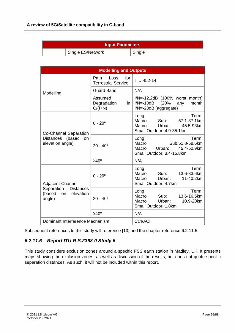
A review of 5G/Satellite compatibility in C-band
© 2021 LS telcom AG October 26, 2021
Page 66/98
Input Parameters
Single ES/Network Single
Modelling and Outputs
Modelling
Path Loss for Terrestrial Service
ITU 452-14
Guard Band N/A
Assumed Degradation in C/(I+N)
I/N=-12.2dB (100% worst month) I/N=-10dB (20% any month I/N=-20dB (aggregate)
Co-Channel Separation Distances (based on elevation angle)
0 - 20⁰
Long Term: Macro Sub: 57.1-87.1km Macro Urban: 45.5-93km Small Outdoor: 4.9-35.1km
20 - 40⁰
Long Term: Macro Sub:51.8-58.6km Macro Urban: 45.4-52.9km Small Outdoor: 3.4-15.8km
≥40⁰ N/A
Adjacent-Channel Separation Distances (based on elevation angle)
0 - 20⁰
Long Term: Macro Sub: 13.6-33.6km Macro Urban: 11-40.2km Small Outdoor: 4.7km
20 - 40⁰
Long Term: Macro Sub: 13.6-16.5km Macro Urban: 10.9-20km Small Outdoor: 1.8km
≥40⁰ N/A
Dominant Interference Mechanism CCI/ACI
Subsequent references to this study will reference [13] and the chapter reference 6.2.11.5.
6.2.11.6 Report ITU-R S.2368-0 Study 6
This study considers exclusion zones around a specific FSS earth station in Madley, UK. It presents
maps showing the exclusion zones, as well as discussion of the results, but does not quote specific
separation distances. As such, it will not be included within this report.

A review of 5G/Satellite compatibility in C-band
© 2021 LS telcom AG October 26, 2021
Page 67/98
6.2.11.7 Report ITU-R S.2368-0 Study 7
This study considers adjacent frequency compatibility analysis between FSS and IMT. Elevation angles
of 5, 15 and 48⁰ are assumed for the FSS receiver. A representative network has been simulated, with
the FSS receiver at the centre.
The assumed input and modelling parameters are shown below, alongside the resulting separation
distances.
Input Parameters
5G
Operating Frequencies 3300 - 3400 MHz
In Band EIRP 14 - 51dBm/MHz
Spurious Emissions 3GPP 36.104 v.11.2.0 45dB ACLR or -15dBm/MHz (wide area) 45dB ACLR or -32dBm/MHz (local)
Single Cell/Network Network
Satellite
Operating Frequencies 3400 - 4200 MHz
Dish Size/Gain 2.4m, 11m
Wanted Signal EIRP N/A
Wanted Signal C/(I+N) N/A
Filter Performance 45dB ACS
LNB Overload N/A
Single ES/Network Single
Modelling and Outputs
Modelling
Path Loss for Terrestrial Service
ITU 452-15
Guard Band N/A
Assumed Degradation in C/(I+N)
I/N=-23dB
Co-Channel Separation Distances (based on elevation angle)
0 - 20⁰ N/A
20 - 40⁰ N/A
≥40⁰ N/A
Adjacent-Channel Separation Distances (based on elevation angle)
0 - 20⁰
5-15deg Macro Sub and Urb: 1400-467m Small Outdoor: 50m Small Indoor: 60-60m

A review of 5G/Satellite compatibility in C-band
© 2021 LS telcom AG October 26, 2021
Page 68/98
Modelling and Outputs
20 - 40⁰ Macro Sub and Urb: 315m Small Outdoor: 50m Small Indoor: 60m
≥40⁰ N/A
Dominant Interference Mechanism CCI/ACI
Subsequent references to this study will reference [13] and the chapter reference 6.2.11.7.
6.2.11.8 Report ITU-R S.2368-0 Study 8
This study investigates the required separation distances for three example FSS earth stations: Madley
(7.7⁰) and Brookmans Park (9.4⁰) in the UK, and Yamaguchi in Japan (6.5⁰). In particular, it aims to
investigate the extent to which terrain close to the earth station helps to reduce the separation distances
required for co-existence of IMT and FSS. Note that the study assumes use of 3400 – 3600 MHz for
the earth stations, despite the band not being allocated to FSS in the UK. In addition, whilst the FSS
antenna pattern references ITU-R S.465, no information is given with regards to dish size, peak gain
etc.
The assumed input and modelling parameters are shown below, alongside the resulting separation
distances.
Input Parameters
5G
Operating Frequencies 3400 - 3600 MHz
In Band EIRP 51dBm/MHz (Macro Suburban and Urban) 22dBm/MHz (Small Outdoor) 17dBm/MHz (Small Indoor)
Spurious Emissions N/A
Single Cell/Network Single
Satellite
Operating Frequencies 3400 - 3600 MHz
Dish Size/Gain N/A
Wanted Signal EIRP N/A
Wanted Signal C/(I+N) N/A
Filter Performance N/A
LNB Overload N/A
Single ES/Network Single

A review of 5G/Satellite compatibility in C-band
© 2021 LS telcom AG October 26, 2021
Page 69/98
Modelling and Outputs
Modelling
Path Loss for Terrestrial Service
ITU 452-14 (with Aster terrain)
Guard Band N/A
Assumed Degradation in C/(I+N)
I/N=-13dB (long term) I/N=-1.3dB (short term)
Co-Channel Separation Distances (based on elevation angle)
0 - 20⁰
Brookmans Park: Macro Sub: 300-350km (sea), 270-300km (land) Macro Urban: 350km (sea), 250-300km (land) Small Outdoor: 70km (land) Small Indoor: 20-55km (land)
Madley: Macro Sub: 450km (sea), 300-350km (land) Macro Urban: 420-450km (sea), 250-350km (land) Small Outdoor: 300km (sea), 120km (land) Small Indoor: 240km (sea), 7-120km (land)
Yamaguchi: Macro Sub: 110km (sea), 60km (land) Macro Urban: 90-125km (sea), 25-60km (land) Small Outdoor: 15km (land) Small Indoor: 10-15km (land)
20 - 40⁰ N/A
≥40⁰ N/A
Adjacent-Channel Separation Distances (based on elevation angle)
0 - 20⁰ N/A
20 - 40⁰ N/A
≥40⁰ N/A
Dominant Interference Mechanism CCI
Subsequent references to this study will reference [13] and the chapter reference 6.2.11.8.
6.2.11.9 Report ITU-R S.2368-0 Study 9
This study considers adjacent frequency interference from a network of IMT base stations centred
around an FSS dish receiving from one of two satellites. The study aims to quantify the size of the guard
band required to reduce interference below the co-ordination trigger level. It convolutes a number of

A review of 5G/Satellite compatibility in C-band
© 2021 LS telcom AG October 26, 2021
Page 70/98
possible IMT out of band emissions masks and FSS receiver masks to produce a net filter discrimination
function. From this, the required guard band can then be determined. It finds that a guard band of 4MHz
is sufficient for small outdoor deployments, and a guard band of 26MHz is sufficient for macro cell
networks. Whilst this is a useful output, it is not directly comparable to the majority of the other studies
considered within this report, and as such the detailed results will not be presented here.
6.2.11.10 Report ITU-R S.2368-0 Study 10
This study considers co-existence between IMT and FSS, aiming to derive both separation distances
and the required frequency dependent rejection of the IMT and FSS spectrum masks. The study
considers both base stations and user equipment. The study assumes a smooth Earth profile. For the
co-channel case, the FSS receiver is positioned next to a single IMT base station, and the distance
varied to determine the required separation distance. For the adjacent frequency case, the distance
between an FSS receiver and the IMT network is varied to determine the required attenuation of the
IMT signal at each distance. The attenuation is then combined with the derived frequency dependent
rejection to determine the guard band required for each separation distance.
The assumed input and modelling parameters are shown below, alongside the resulting separation
distances. Note that in the below tables, where a range is given for the separation distances, it either
depends on the extent of the misalignment between the IMT and FSS antennas in the horizontal plane,
or the guard band which is shown in brackets.
Input Parameters
5G
Operating Frequencies 3400 – 4200 MHz
In Band EIRP 36dBm/MHz (Macro Suburban and Urban) 14dBm/MHz (Small Outdoor and Indoor) 14 to -50dBm/MHz (UE)
Spurious Emissions
BS 1st Adj: -45dB 2nd Adj: -45dB Spurious: -54dB
UE 1st Adj: -30dB 2nd Adj: -33dB Spurious: -53dB
Single Cell/Network Network
Satellite
Operating Frequencies 3400 – 4200 MHz
Dish Size/Gain 3m
Wanted Signal EIRP N/A
Wanted Signal C/(I+N) N/A
Filter Performance 1st Adj:-45dB 2nd Adj:-50dB >2nd Adj:-55dB

A review of 5G/Satellite compatibility in C-band
© 2021 LS telcom AG October 26, 2021
Page 71/98
Input Parameters
LNB Overload N/A
Single ES/Network Single
Modelling and Outputs
Modelling
Path Loss for Terrestrial Service
ITU 452-14
Guard Band 0-103.3MHz
Assumed Degradation in C/(I+N)
I/N=-13dB (co-channel) I/N=-23dB (adj channel)
Co-Channel Separation Distances (based on elevation angle)
0 - 20⁰
BS: Macro Sub: 27.7-50km Macro Urban: 28.3-48km Small Outdoor: 2.8-16km Small Indoor: <1km
UE: Macro Sub: <1km Macro Urban: <2km Small Outdoor: <1km Small Indoor: <1km
20 - 40⁰ N/A
≥40⁰ N/A
Adjacent-Channel Separation Distances (based on elevation angle)
0 - 20⁰
BS: Macro Sub: 20-30km (103.3-25MHz) Macro Urban: 20-30km (98.7-25MHz) Small Outdoor: 1-30km (40-16.3MHz) Small Indoor: 1-30km (22-4.8MHz)
UE: 0MHz GB for all distances
20 - 40⁰
BS: Macro Sub: 5-30km (39.8-24.5MHz) Macro Urban: 5-30km (25-24.7MHz) Small Outdoor: 1-30km (25-5MHz) Small Indoor: 1-30km (4.8-4.6MHz)
UE: 0MHz GB for all distances
≥40⁰ N/A

A review of 5G/Satellite compatibility in C-band
© 2021 LS telcom AG October 26, 2021
Page 72/98
Modelling and Outputs
Dominant Interference Mechanism CCI/ACI
Subsequent references to this study will reference [13] and the chapter reference 6.2.11.11.
6.2.11.11 Report ITU-R S.2368-0 Study 11
This study considers the co-existence of BWA services with FSS. Interfering signal level limits have not
been calculated. Rather levels measured in typical LNBs in Brazil have been used, and additional
attenuation stated that would be required on a typical installation in order for coexistence to be possible.
As this is not comparable with the majority of studies considered within this report, the detailed results
will not be presented here.
6.2.12 Report for GSMA on the mitigations required for adjacent frequency compatibility between IMT and ubiquitous FSS Earth Stations in the 3.4 – 3.8 GHz frequency band
This study [14] was completed by Transfinite Systems on behalf of GSMA. It considers the spectral
separation required, based on a fixed set of parameters, to allow adjacent frequency coexistence of
IMT and FSS. The study focusses on a single test point FSS earth station in Pretoria, South Africa, with
links to two satellites, giving different elevation angles (5⁰ and 27.5⁰) and azimuths. Monte Carlo
simulations are used to position the earth station randomly within a 300m hexagonal area surrounding
the centre of the IMT network deployment. Each base station is assumed to transmit at full power at a
single user terminal located randomly within its cell.
The study utilises the net frequency discrimination (NFD) method to determine the required guard band
based on an allowable I/N degradation of 10dB for at least 50% of all possible deployments, although
the results are presented such that guard bands for other degradation values are available also. A
number of different spectrum masks are included in the net frequency discrimination analysis. Full
details of the results are available within [14], with results for an I/N=-10dB included here.
The assumed input and modelling parameters are shown below, alongside the resulting guard band
required.
Input Parameters
5G
Operating Frequencies 3400 - 3600 MHz
In Band EIRP 27dBm/MHz (Macro Urban) 5dBm/MHz (Small Outdoor)
Spurious Emissions
Macro: 0 MHz <= df < 1 MHz: 2dBm/MHz 1 MHz <= df <= 5MHz: interpolate 2 to -4dBm/MHz 5 MHz <= df <= 10MHz: -4dBm/MHz > 10MHz: -13dBm/MHz
Small 0 MHz <= df <= 1MHz: interpolate 5 to -43dBm/MHz

A review of 5G/Satellite compatibility in C-band
© 2021 LS telcom AG October 26, 2021
Page 73/98
Input Parameters
1 MHz <= df <= 5MHz: interpolate -43 to -49dBm/MHz > 5MHz: -49dBm/MHz
Single Cell/Network Network
Satellite
Operating Frequencies 3600 - 3800 MHz
Dish Size/Gain 1.8m
Wanted Signal EIRP N/A
Wanted Signal C/(I+N) N/A
Filter Performance IDA, or Gaussian (2 x bandwidth at -30, -40, -50 and -60dB)
LNB Overload -60dBm
Single ES/Network Single
Modelling and Outputs
Modelling
Path Loss for Terrestrial Service
ITU 452-16
Guard Band 18MHz
Assumed Degradation in C/(I+N)
I/N=-10dB
Co-Channel Separation Distances (based on elevation angle)
0 - 20⁰ N/A
20 - 40⁰ N/A
≥40⁰ N/A
Adjacent-Channel Separation Distances (based on elevation angle)
0 - 20⁰ N/A
20 - 40⁰ N/A
≥40⁰ N/A
Dominant Interference Mechanism ACI
Subsequent references to this study will reference [14] and the chapter reference 6.2.12.
6.2.13 Assessments on and Recommendations to Enable the Electromagnetic Compatibility between Public Mobile Services and Fixed Satellite Service Operating in the C-Band
This study [15] was conducted by Rohde & Schwarz on behalf of The Office of Communications
Authority (OFCA), Hong Kong. It considers the mitigation measures required to allow compatibility of
existing FSS systems with future public mobile services. The study investigates the RF performance of
a number of FSS system components, before considering a theoretical set of scenarios to determine
the possibility for compatibility. It then goes on to verify these test cases through the use of field testing.

A review of 5G/Satellite compatibility in C-band
© 2021 LS telcom AG October 26, 2021
Page 74/98
The assumed input and modelling parameters are shown below.
Input Parameters
5G
Operating Frequencies 3700 - 4200 MHz
In Band EIRP
38dBm/MHz (Macro)
16dBm/MHz (Outdoor small)
11dBm/MHz (Small indoor)
Spurious Emissions -52dBm/MHz
Single Cell/Network Single/Two
Satellite
Operating Frequencies 3700 - 4200 MHz
Dish Size/Gain 3m, 40dBi
Wanted Signal EIRP N/A
Wanted Signal C/(I+N) N/A
Filter Performance 3600, >55dB rejection
4200, >50dB rejection
LNB Overload -52dBm
Single ES/Network Single
Modelling and Outputs
Modelling
Path Loss for Terrestrial Service
Free space, diffraction as per ITU-R P.526-7, insertion loss
Guard Band 50MHz or 100MHz
Assumed Degradation in C/(I+N)
N/A
Co-Channel Separation Distances (based on elevation angle)
0 - 20⁰ N/A
20 - 40⁰ N/A
≥40⁰ N/A
Adjacent-Channel Separation Distances (based on elevation angle)
0 - 20⁰ N/A
20 - 40⁰ N/A
≥40⁰ N/A
Dominant Interference Mechanism LNB saturation
Subsequent references to this study will reference [15] and the chapter reference 6.2.13.

A review of 5G/Satellite compatibility in C-band
© 2021 LS telcom AG October 26, 2021
Page 75/98
6.3 Summary of Studies
6.3.1 Studies
Reference Chapter Reference Study Authors Date Organisation Country
[3] 6.2.1 5G Cellular and FSS Spectrum Coexistence
in C-Band
EVA LAGUNAS, CHRISTOS G. TSINOS,
SHREE K. SHARMA, and SYMEON CHATZINOTAS
2020 University of Luxembourg Luxembourg
[4] 6.2.2 The Interference Mitigation Method and Field Test in C-Band Between 5G System
and FSS Receiver
Yushan Pei, Fuchang Li, Yao Zhou, Yi Feng and
Yuande Tan 2020
China United Network Communications Group
Co. Ltd China
[5] 6.2.3 IMT-FSS Coexistence Scenarios IN C-Band
GSM Association (Hong Kong)
2014 GSM Association (Hong
Kong) Hong Kong
[6] 6.2.4 BEST PRACTICES FOR TERRESTRIAL-SATELLITE COEXISTENCE DURING AND
AFTER THE C-BAND TRANSITION
TECHNICAL WORKING GROUP #1
2020 TECHNICAL WORKING
GROUP #1 USA
[7] 6.2.5 Coexistence for LTE-Advanced and FSS Services in the 3.5GHz Band in Colombia
German Castellanos, Guillermo Teuta, Hernan Paz Penagos and Wout
Joseph
2019 Colombian School of
Engineering Columbia
[8] 6.2.6 COEXISTENCE STUDIES BETWEEN LTE SYSTEM AND EARTH STATION OF
FIXED SATELLITE SERVICE IN THE 3400-3600 MHZ FREQUENCY BANDS IN CHINA
Weidong Wang, Fei Zhou, Wei Huang, Ben Wang,
Yinghai Zhang 2010
Beijing University of Posts and Telecommunications
China
[9] 6.2.7 Coexistence conditions of LTE-advanced at 3400–3600 MHz with TVRO at 3625–4200
MHz in Brazil
Leandro Carı´sio Fernandes, Agostinho
Linhares 2017
National Telecommunications
Agency Brazil Brazil

A review of 5G/Satellite compatibility in C-band
© 2021 LS telcom AG October 26, 2021
Page 76/98
Reference Chapter Reference Study Authors Date Organisation Country
[10] 6.2.8 Interference Mitigation Technique for the Sharing between IMT-Advanced and Fixed
Satellite Service
JaeWoo Lim, Han-Shin Jo, Hyun-Goo Yoon, and Jong-
Gwan Yook 2007 Various Universities China
[11] 6.2.9 Geographic Sharing in C-band Transfinite 2015 Transfinite, Ofcom UK
[12] 6.2.10 Rep. ITU-R M.2109 Sharing studies between IMT-Advanced systems and
geostationary satellite networks in the fixed-satellite service in the 3 400-4 200 and 4
500-4 800 MHz frequency bands
ITU 2007 ITU Various
[12] 6.2.10.3 Rep. ITU-R M.2109 Study 3 ITU 2007 ITU Various
[12] 6.2.10.4 Rep. ITU-R M.2109 Study 4 ITU 2007 ITU Various
[12] 6.2.10.5 Rep. ITU-R M.2109 Study 5 ITU 2007 ITU Various
[12] 6.2.10.6 Rep. ITU-R M.2109 Study 6 ITU 2007 ITU Various
[12] 6.2.10.7 Rep. ITU-R M.2109 Study 7 ITU 2007 ITU Various
[12] 6.2.10.9 Rep. ITU-R M.2109 Study 9 ITU 2007 ITU Various
[13] 6.2.11 Report ITU-R S.2368-0 Sharing studies between International Mobile
Telecommunication-Advanced systems and geostationary satellite networks in the fixed-satellite service in the 3 400-4 200 MHz and
4 500-4 800 MHz frequency bands in the WRC study cycle…
ITU 2015 ITU Various
[13] 6.2.11.1 Report ITU-R S.2368-0 Study 1 ITU 2015 ITU Various
[13] 6.2.11.2 Report ITU-R S.2368-0 Study 2 ITU 2015 ITU Various
[13] 6.2.11.3 Report ITU-R S.2368-0 Study 3 ITU 2015 ITU Various
[13] 6.2.11.4 Report ITU-R S.2368-0 Study 4 ITU 2015 ITU Various

A review of 5G/Satellite compatibility in C-band
© 2021 LS telcom AG October 26, 2021
Page 77/98
Reference Chapter Reference Study Authors Date Organisation Country
[13] 6.2.11.7 Report ITU-R S.2368-0 Study 7 ITU 2015 ITU Various
[13] 6.2.11.8 Report ITU-R S.2368-0 Study 8 ITU 2015 ITU Various
[13] 6.2.11.10 Report ITU-R S.2368-0 Study 10 ITU 2015 ITU Various
[14] 6.2.12 Report for GSMA on the mitigations required for adjacent frequency compatibility
between IMT and ubiquitous FSS Earth Stations in the 3.4 – 3.8 GHz frequency
band
Transfinite 2019 Transfinite, GSMA South Africa
[15] 6.2.13 Assessments on and Recommendations to Enable the Electromagnetic Compatibility
between Public Mobile Services and Fixed Satellite Service Operating in the C-Band
Rohde & Schwarz 2018 OFCA Hong Kong

A review of 5G/Satellite compatibility in C-band
© 2021 LS telcom AG October 26, 2021
Page 78/98
6.3.2 5G Input Assumptions
Ref No
Chapter No
Band In Band EIRP Spurious Emissions Single Cell/Network
[3] 6.2.1 3400 - 3700 MHz OR
3410 - 3620 MHz 54dBm/MHz
0 MHz <= df < 5 MHz: Min(Pmax-47,14) dBm/MHz 5 MHz <= df < 10 MHz: Min(Pmax-50,8) dBm/MHz 10 MHz <= df <=fmax: Min(Pmax-50,6) dBm/MHz
Both
[4] 6.2.2 3500 - 3600MHz ~44dBm/MHz
50 MHz <= df > 100MHz: -26dBm/MHz 100 MHz <= df < 600 MHz: -47dBm/MHz
Both
[5] 6.2.3 3400 - 3600 MHz 27dBm/MHz N/A Single
[6] 6.2.4 3700 - 3980 MHz
65dBm/MHz (rural) 62dBm/MHz (urban)
-13dBm/MHz -40dBm/MHz
Single
[7] 6.2.5 3664 - 3718 MHz
48dBm/MHz Suburban 45dBm/MHz Urban
13dBm/MHz UE N/A Single
[8] 6.2.6
3400 - 3600 MHz 36dBm/MHz (BS) 14dBm/MHz (UE)
BS 0MHz <= df < 5MHz: -4.65dBm/MHz 5MHz <= df <10 MHz: -11dBm/MHz
10MHz <= df: -11dBm/MHz
UE 0MHz <= df < 1MHz: -2.7712dBm/MHz 1MHz <= df <5MHz: -16.02dBm/MHz 5MHz <= df <10MHz: -20dBm/MHz 10MHz <= df <15MHz: -32dBm/MHz
15MHz <= df: -84dBm/MHz
Both
[9] 6.2.7
3400 - 3600 MHz
Suburban Macro: 34, 40, 45dBm/MHz
Urban Macro:
27, 39, 45dBm/MHz
BS: 3GPP TS 36.104 v13.2.0
UE: 3GPP TS 36.101 v14.0.0 Both
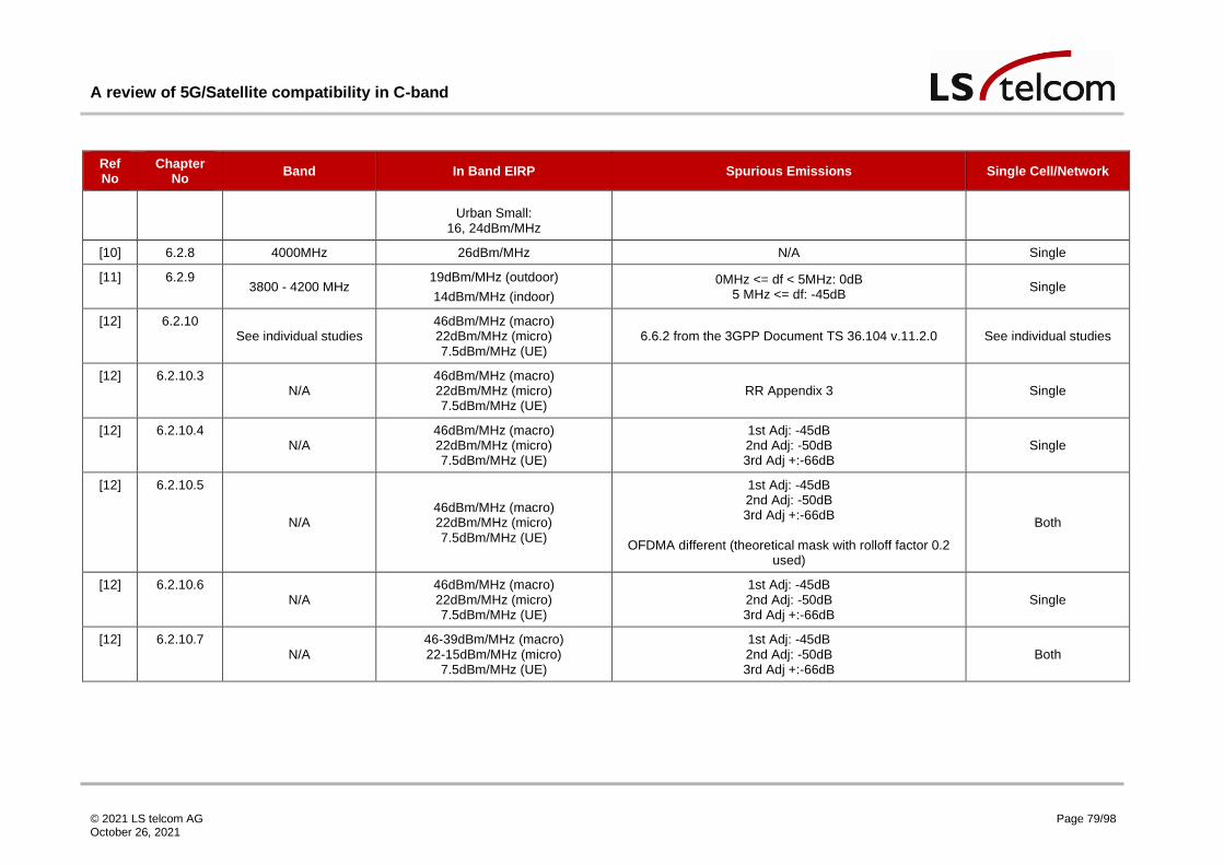
A review of 5G/Satellite compatibility in C-band
© 2021 LS telcom AG October 26, 2021
Page 79/98
Ref No
Chapter No Band In Band EIRP Spurious Emissions Single Cell/Network
Urban Small:
16, 24dBm/MHz
[10] 6.2.8 4000MHz 26dBm/MHz N/A Single
[11] 6.2.9 3800 - 4200 MHz
19dBm/MHz (outdoor)
14dBm/MHz (indoor)
0MHz <= df < 5MHz: 0dB 5 MHz <= df: -45dB
Single
[12] 6.2.10 See individual studies
46dBm/MHz (macro) 22dBm/MHz (micro) 7.5dBm/MHz (UE)
6.6.2 from the 3GPP Document TS 36.104 v.11.2.0 See individual studies
[12] 6.2.10.3 N/A
46dBm/MHz (macro) 22dBm/MHz (micro) 7.5dBm/MHz (UE)
RR Appendix 3 Single
[12] 6.2.10.4 N/A
46dBm/MHz (macro) 22dBm/MHz (micro) 7.5dBm/MHz (UE)
1st Adj: -45dB 2nd Adj: -50dB 3rd Adj +:-66dB
Single
[12] 6.2.10.5
N/A 46dBm/MHz (macro) 22dBm/MHz (micro) 7.5dBm/MHz (UE)
1st Adj: -45dB 2nd Adj: -50dB 3rd Adj +:-66dB
OFDMA different (theoretical mask with rolloff factor 0.2
used)
Both
[12] 6.2.10.6 N/A
46dBm/MHz (macro) 22dBm/MHz (micro) 7.5dBm/MHz (UE)
1st Adj: -45dB 2nd Adj: -50dB 3rd Adj +:-66dB
Single
[12] 6.2.10.7 N/A
46-39dBm/MHz (macro) 22-15dBm/MHz (micro)
7.5dBm/MHz (UE)
1st Adj: -45dB 2nd Adj: -50dB 3rd Adj +:-66dB
Both

A review of 5G/Satellite compatibility in C-band
© 2021 LS telcom AG October 26, 2021
Page 80/98
Ref No
Chapter No Band In Band EIRP Spurious Emissions Single Cell/Network
[12] 6.2.10.9 N/A
46dBm/MHz (macro) 22dBm/MHz (micro) 7.5dBm/MHz (UE)
3GPP TS 25.104 V7.5.0 Single
[13] 6.2.11 See individual studies 24dBm - 61dBm 6.6.2 from the 3GPP Document TS 36.104 v.11.2.0 See individual studies
[13] 6.2.11.1
3400 - 4200 MHz
48dBm/MHz (Macro Urban & Suburban)
16dBm/MHz (Small Outdoor) 11dBm/MHz (Small Indoor)
N/A Single
[13] 6.2.11.2
N/A
3dB Less for Aggregate Simulation: 48dBm/MHz (Suburban Macro)
33dBm/MHz (Urban Macro) 16dBm/MHz (Outdoor Small) 11dBm/MHz (Indoor Small)
3GPP 36.104 v.11.2.0 Network
[13] 6.2.11.3 3400 - 3600 MHz
33dBm/MHz (Macro Suburban) 17dBm/MHz (Small Outdoor)
TS 36.104 v.11.2.0 Single
[13] 6.2.11.4 3400 - 4200 MHz 14 - 51dBm/MHz TS 36.104 v.11.2.0 Both
[13] 6.2.11.7 3300 - 3400 MHz 14 - 51dBm/MHz
3GPP 36.104 v.11.2.0 45dB ACLR or -15dBm/MHz (wide area)
45dB ACLR or -32dBm/MHz (local) Network
[13] 6.2.11.8
3400 - 3600 MHz
51dBm/MHz (Macro Suburban and Urban)
22dBm/MHz (Small Outdoor) 17dBm/MHz (Small Indoor)
N/A Single
[13] 6.2.11.10
3400 – 4200 MHz
36dBm/MHz (Macro Suburban and Urban)
14dBm/MHz (Small Outdoor and Indoor)
14 to -50dBm/MHz (UE)
BS 1st Adj: -45dB 2nd Adj: -45dB
Spurious: -54dB
UE
Network

A review of 5G/Satellite compatibility in C-band
© 2021 LS telcom AG October 26, 2021
Page 81/98
Ref No
Chapter No Band In Band EIRP Spurious Emissions Single Cell/Network
1st Adj: -30dB 2nd Adj: -33dB
Spurious: -53dB
[14] 6.2.12
3400 - 3600 MHz 27dBm/MHz (Macro Urban) 5dBm/MHz (Small Outdoor)
Macro: 0 MHz <= df < 1 MHz: 2dBm/MHz
1 MHz <= df <= 5MHz: interpolate 2 to -4dBm/MHz 5 MHz <= df <= 10MHz: -4dBm/MHz
> 10MHz: -13dBm/MHz
Small 0 MHz <= df <= 1MHz: interpolate 5 to -43dBm/MHz
1 MHz <= df <= 5MHz: interpolate -43 to -49dBm/MHz > 5MHz: -49dBm/MHz
Network
[15] 6.2.13
3700 – 4200 MHz
38dBm/MHz (Macro)
16dBm/MHz (Outdoor small)
11dBm/MHz (Small indoor)
-52dBm/MHz Single/Two

A review of 5G/Satellite compatibility in C-band
© 2021 LS telcom AG October 26, 2021
Page 82/98
6.3.3 FSS Input Assumptions
Ref No
Chapter No
Band Dish Size/Gain Wanted Signal EIRP
Wanted Signal C/(I+N)
Filter Performance LNB Overload Single
ES/Network
[3] 6.2.1 3400 - 3700 MHz OR 3410 - 3620
MHz 4.8m - 12m N/A N/A
Square root raised cosine (-20dB at 3.55GHz, -60dB at 3.4GHz)
-63dBm with added 25dB or 10dB
margin Single
[4] 6.2.2 3500 - 3600MHz
1.8m - 3m (aligned with BS)
N/A N/A Minimum of -45dB in adjacent band -60dBm Single
[5] 6.2.3 3400 - 3600 MHz 1.8m, 34.17dBi (peak) 47.7dBW 17.01dB N/A N/A Single
[6] 6.2.4
3700 - 3980 MHz N/A N/A N/A
0 MHz <= df < 15 MHz: 0dB 15 MHz <= df < 20 MHz: -30dB 20 MHz <= df < 100MHz: -60dB
df > 100MHz: -70dB
-16dBW/m^2/MHz Single
[7] 6.2.5 3664 - 3718 MHz
-8.6dBi, -1.6dBi, 6.2dBi
90dBm N/A N/A N/A Single
[8] 6.2.6 3400 - 3600 MHz 4m N/A N/A N/A -60dBm Single
[9] 6.2.7 3400 - 3600 MHz
0dBi, -4dBi, -10dBi (32dBi peak gain)
N/A N/A N/A -60dBm, -45dBm TVRO
[10] 6.2.8 4000MHz 3.8m N/A N/A N/A N/A Single
[11] 6.2.9 3800 - 4200 MHz 55dBi N/A N/A
Gaussian, -30dB at 2 x transponder bandwidth
N/A Single
[12] 6.2.10 See individual studies
[12] 6.2.10.3 N/A 1.8m-3.8m, 11m N/A N/A N/A N/A Single
[12] 6.2.10.4 N/A 2.4m N/A N/A N/A N/A Single
[12] 6.2.10.5 N/A 1.8m-3.8m, 11m N/A N/A N/A N/A Single

A review of 5G/Satellite compatibility in C-band
© 2021 LS telcom AG October 26, 2021
Page 83/98
Ref No
Chapter No
Band Dish Size/Gain Wanted Signal EIRP
Wanted Signal C/(I+N)
Filter Performance LNB Overload Single
ES/Network
[12] 6.2.10.6 N/A 1.8m-3.8m, 11m N/A N/A N/A N/A Single
[12] 6.2.10.7 N/A 1.8m-3.8m, 11m N/A N/A N/A N/A Single
[12] 6.2.10.9 N/A 1.8m-3.8m, 11m N/A N/A N/A -60dBm Single
[13] 6.2.11 See individual studies
[13] 6.2.11.1 3400 - 4200 MHz 2.4m, 16m N/A N/A N/A N/A Single
[13] 6.2.11.2 N/A 2.4m, 10m N/A N/A N/A -55dBm Single
[13] 6.2.11.3 3400 - 3600 MHz 18m N/A N/A N/A -50 to -60dBm Single
[13] 6.2.11.4 3400 - 4200 MHz N/A N/A N/A N/A -61dBm Both
[13] 6.2.11.7 3300 - 3400 MHz 2.4m, 11m N/A N/A 45dB ACS N/A Single
[13] 6.2.11.8 3400 - 3600 MHz N/A N/A N/A N/A N/A Single
[13] 6.2.11.10 3400 – 4200 MHz 3m N/A N/A
1st Adj:-45dB 2nd Adj:-50dB
>2nd Adj:-55dB N/A Single
[14] 6.2.12 3400 - 3600 MHz 1.8m N/A N/A
IDA, or Gaussian (2 x bandwidth at -30, -40, -50 and -60dB)
-60dBm Single
[15] 6.2.13 3700 – 4200 MHz 3m, 40dBi N/A N/A
3600, >55dB rejection
4200, >50dB rejection -52dBm Single

A review of 5G/Satellite compatibility in C-band
© 2021 LS telcom AG October 26, 2021
Page 84/98
6.3.4 Modelling Assumptions
Ref No Chapter No Path Loss for Terrestrial Service Guard Band (MHz) Assumed Degradation in C/(I+N)
[3] 6.2.1 ITU-R 452-16 5MHz I/N = -10dB
[4] 6.2.2 Measured received 5G power 100MHz OR 25MHz N/A
[5] 6.2.3 ITU R 452-15 N/A C/(I+N) = 8.69dB (reduction of ~8dB)
[6] 6.2.4 Free space and ITS Irregular Terrain Model 20MHz I/N=-6dB (adjusted down by 4dB)
[7] 6.2.5 ITU R 2001-2 OR ITU-R 452-16 -28 to +25MHz I/N = -6.5dB
[8] 6.2.6 ITU R 452-12 0MHz - 15MHz I/N = -12.2dB
[9] 6.2.7 ITU R 452-16 (using free space for short distances, 452 for long distances, and linear interpolation between the two for mid range)
25MHz N/A
[10] 6.2.8 ITU 452-12 -9 to 9MHz I/N=-12.2dB
[11] 6.2.9 ITU 452-15 N/A I/N = -10dB
[12] 6.2.10 See individual studies
[12] 6.2.10.3
ITU 452-12 with diffraction and ducting models N/A
I/N=-12.2dB (long term) I/N=-15.2dB (long term, int
apportionment) I/N=-20dB (adjacent)
[12] 6.2.10.4 ITU 452-12, LoS with sub-path diffraction N/A
I/N=-12.2dB (long term) I/N=-20dB (adjacent)
[12] 6.2.10.5 ITU 452-12 N/A
I/N=-12.2dB (long term) I/N=-20dB (adjacent)
[12] 6.2.10.6
ITU 452-12, smooth earth with diffraction N/A
I/N=-12.2dB (long term) I/N=-15.2dB (long term, int
apportionment) I/N=-20dB (adjacent)

A review of 5G/Satellite compatibility in C-band
© 2021 LS telcom AG October 26, 2021
Page 85/98
Ref No Chapter No Path Loss for Terrestrial Service Guard Band (MHz) Assumed Degradation in C/(I+N)
[12] 6.2.10.7 ITU 452-12 N/A
I/N=-12.2dB (long term) I/N=-20dB (adjacent)
[12] 6.2.10.9 ITU 452-12, LoS w/o sub-path diffraction, multipath or focussing effects N/A
I/N=-12.2dB (long term) I/N=-20dB (adjacent)
[13] 6.2.11 See individual studies
[13] 6.2.11.1 ITU 452-14, smooth Earth N/A
I/N = -13dB (long term) I/N = -1.3dB (short term, single entry)
[13] 6.2.11.2
ITU 452-14 0, 5, 10MHz I/N = -13dB (long term)
I/N = -1.3dB (short term, single entry) I/N = -20dB (aggregate, ACI)
[13] 6.2.11.3 ITU 452-14 N/A
I/N=-10dB (long term) I/N=-1.3dB (short term)
[13] 6.2.11.4 ITU 452-14 N/A (stated 0MHz for LNB) ITU-R S.1432 and ITU-R SF.1006
[13] 6.2.11.7 ITU 452-15 N/A I/N=-23dB
[13] 6.2.11.8 ITU 452-14 (with Aster terrain) N/A
I/N=-13dB (long term) I/N=-1.3dB (short term)
[13] 6.2.11.10 ITU 452-14 0-103.3MHz
I/N=-13dB (co-channel) I/N=-23dB (adj channel)
[14] 6.2.12 ITU 452-16 18MHz I/N=-10dB
[15] 6.2.13 Free space, diffraction as per ITU-R P.526-7, insertion loss 50MHz, 100MHz N/A
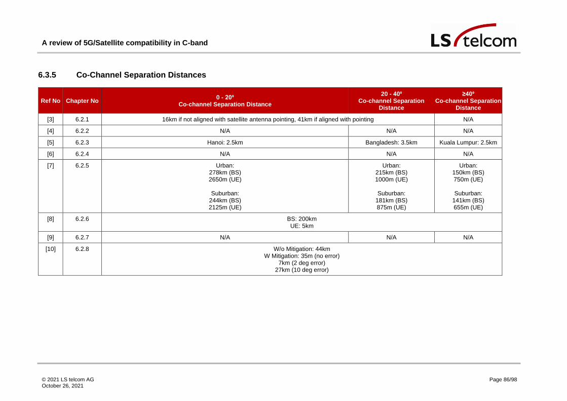
A review of 5G/Satellite compatibility in C-band
© 2021 LS telcom AG October 26, 2021
Page 86/98
6.3.5 Co-Channel Separation Distances
Ref No Chapter No 0 - 20⁰
Co-channel Separation Distance
20 - 40⁰ Co-channel Separation
Distance
≥40⁰ Co-channel Separation
Distance
[3] 6.2.1 16km if not aligned with satellite antenna pointing, 41km if aligned with pointing N/A
[4] 6.2.2 N/A N/A N/A
[5] 6.2.3 Hanoi: 2.5km Bangladesh: 3.5km Kuala Lumpur: 2.5km
[6] 6.2.4 N/A N/A N/A
[7] 6.2.5 Urban: 278km (BS) 2650m (UE)
Suburban:
244km (BS) 2125m (UE)
Urban: 215km (BS) 1000m (UE)
Suburban:
181km (BS) 875m (UE)
Urban: 150km (BS) 750m (UE)
Suburban:
141km (BS) 655m (UE)
[8] 6.2.6 BS: 200km UE: 5km
[9] 6.2.7 N/A N/A N/A
[10] 6.2.8 W/o Mitigation: 44km W Mitigation: 35m (no error)
7km (2 deg error) 27km (10 deg error)

A review of 5G/Satellite compatibility in C-band
© 2021 LS telcom AG October 26, 2021
Page 87/98
Ref No Chapter No 0 - 20⁰
Co-channel Separation Distance
20 - 40⁰ Co-channel Separation
Distance
≥40⁰ Co-channel Separation
Distance
[11] 6.2.9 Chalfont Outdoor BS:
25km (1. flat Earth) 73km (2. terrain, but no clutter)
70km (3. as 2, with clutter) 25km (4. as 3, with extra dense urban clutter loss)
24km (5. as 4, with polarisation discrimination, traffic considerations)
3km (indoor BS)
N/A N/A
[12] 6.2.10 >10s of km
[12] 6.2.10.3 (I/N=-12.2dB) Macro: 55km Mobile: 1km
(I/N=-15.2dB) Macro: 70km Mobile: 1.5km
[12] 6.2.10.4 Macro Urban: 37-54km Micro Urban: 15-23km Macro rural: 40-59km
[12] 6.2.10.5 Single Entry: Base Station: 45-58km (5-48 deg)
Aggregate:
Base Station: 51-60km (5-48deg) Mobile Station: 0.5-1.5km

A review of 5G/Satellite compatibility in C-band
© 2021 LS telcom AG October 26, 2021
Page 88/98
Ref No Chapter No 0 - 20⁰
Co-channel Separation Distance
20 - 40⁰ Co-channel Separation
Distance
≥40⁰ Co-channel Separation
Distance
[12] 6.2.10.6 (I/N=-12.2dB) 5deg: 33-57km
15deg: 33-37km
(I/N=-15.2dB) 5deg: 36-60km
15deg: 36-40km
[12] 6.2.10.7 Single Entry: CDMA Macro: 47-65.6km CDMA Micro: 39-49.5km
CDMA Mobile: 0km OFDMA Macro: 43-55km OFDMA Micro: 29-47km
OFDMA Mobile: 0km
Aggregate: CDMA Macro: 56-87km CDMA Micro: 49-58km
CDMA Mobile: 0km OFDMA Macro: 51-61km OFDMA Micro: 46-53km
OFDMA Mobile: 0km
[12] 6.2.10.9 N/A N/A N/A
[13] 6.2.11 CCI Macro cell: 10s of km/100s of km (long term/short term int) Small cell: 10s of km
Small Indoor: 5 to 10s of km

A review of 5G/Satellite compatibility in C-band
© 2021 LS telcom AG October 26, 2021
Page 89/98
Ref No Chapter No 0 - 20⁰
Co-channel Separation Distance
20 - 40⁰ Co-channel Separation
Distance
≥40⁰ Co-channel Separation
Distance
[13] 6.2.11.1 Long Term: Macro Sub: 61-63km
Macro Urban: 46-48km Small Outdoor: 25km Small Indoor: <5km
N/A
Long Term: Macro Sub: 35-36km
Macro Urban: 20-22km Small Outdoor: 6km Small Indoor: <5km
[13] 6.2.11.2 Long Term:
Macro Sub: 60.5km Macro Urb: 72km
Small Outdoor: 5km Small Indoor: 4-5km
Long Term (15 deg): Macro Sub: 58.2km Macro Urb: 69km
Small Outdoor: 1.2km Small Indoor: 1-3km
Long Term: Macro Sub: 55.6km Macro Urb: 67km
Small Outdoor: 0.53km Small Indoor: 0.55-
1.5km
[13] 6.2.11.3 Macro suburban: 30-40km Small Outdoor: 15-25km
Macro suburban: 10-20km Small Outdoor: 15-25km
N/A
[13] 6.2.11.4 Long Term (5-10deg): Macro Suburban: 58.1-50.5km
Macro Urban: 51.2-45.2km Small Urban: 20.3-9km
Aggregated:
Macro Suburban: 63-55km Macro Urban: 53-48km
Small Urban: 20.3-10km
Long Term (20-30deg): Macro Suburban: 45.7-44.6km
Macro Urban: 40-35.7km Small Urban: 8.3-6.2km
Aggregated:
Macro Suburban: 53-52km Macro Urban: 45-44km
Small Urban: 9km
N/A
[13] 6.2.11.7 N/A N/A N/A

A review of 5G/Satellite compatibility in C-band
© 2021 LS telcom AG October 26, 2021
Page 90/98
Ref No Chapter No 0 - 20⁰
Co-channel Separation Distance
20 - 40⁰ Co-channel Separation
Distance
≥40⁰ Co-channel Separation
Distance
[13] 6.2.11.8 Brookmans Park: Macro Sub: 300-350km (sea), 270-300km (land) Macro Urban: 350km (sea), 250-300km (land)
Small Outdoor: 70km (land) Small Indoor: 20-55km (land)
Madley:
Macro Sub: 450km (sea), 300-350km (land) Macro Urban: 420-450km (sea), 250-350km (land)
Small Outdoor: 300km (sea), 120km (land) Small Indoor: 240km (sea), 7-120km (land)
Yamaguchi:
Macro Sub: 110km (sea), 60km (land) Macro Urban: 90-125km (sea), 25-60km (land)
Small Outdoor: 15km (land) Small Indoor: 10-15km (land)
N/A N/A
[13] 6.2.11.10 BS: Macro Sub: 27.7-50km
Macro Urban: 28.3-48km Small Outdoor: 2.8-16km
Small Indoor: <1km UE:
Macro Sub: <1km Macro Urban: <2km
Small Outdoor: <1km Small Indoor: <1km
N/A N/A
[14] 6.2.12 N/A N/A N/A
[15] 6.2.13 N/A N/A N/A

A review of 5G/Satellite compatibility in C-band
© 2021 LS telcom AG October 26, 2021
Page 91/98
6.3.6 Adjacent Frequency Separation Distances
Ref No Chapter
No 0 - 20⁰
Adjacent Frequency Separation Distance 20 - 40⁰
Adjacent Frequency Separation Distance ≥40⁰
Adjacent Frequency Separation Distance
[3] 6.2.1 ~14km UE: 550m
N/A
[4] 6.2.2 90m N/A N/A
[5] 6.2.3 N/A N/A N/A
[6] 6.2.4 Passive Antenna: -13dBm/MHz: 26.6km (8.6-20.2km for ITS model)
-40dBm/MHz: 1.2km
AAS: -13dBm/MHz: 0.2km (7%), 1.5-2km (49%), 5.5km (96%)
-40dBm/MHz: <0.2km (7%), <0.2km (49%), <0.3km (96%)
LNB: Rural: 102m
Urban: 73.2m
[7] 6.2.5 Urban: 210 - 88km (BS)
1000 - 380m (UE)
Suburban: 183 - 67km (BS) 975 - 500m (UE)
Urban: 153 - 40km (BS) 650 - 200m (UE)
Suburban:
133 - 28km (BS) 500 - 465m (UE)
Urban: 103 - 18km (BS) 480 - 200m (UE)
Suburban:
83 - 13km (BS) 500 - 265m (UE)

A review of 5G/Satellite compatibility in C-band
© 2021 LS telcom AG October 26, 2021
Page 92/98
Ref No Chapter
No 0 - 20⁰
Adjacent Frequency Separation Distance 20 - 40⁰
Adjacent Frequency Separation Distance ≥40⁰
Adjacent Frequency Separation Distance
[8] 6.2.6 0MHz GB BS: 4.5km UE: 450m
5-10MHz GB
BS: 2km UE: 100m
>10MHz GB BS: 800m
LNB: 500m
[9] 6.2.7 -60dBm LNB: Suburban Macro: not possible
Urban Macro: not possible Urban Small: 80-70m
-45dBm LNB
Suburban Macro: 430-230m Urban Macro: 120-60m Urban Small: 50-30m
-60dBm LNB: Suburban Macro: not possible
Urban Macro: not possible Urban Small: 70m
-45dBm LNB
Suburban Macro: 245-110m Urban Macro: 90-10m Urban Small: 40-15m
-60dBm LNB: Suburban Macro: not possible
Urban Macro: 270-95m Urban Small: 60-50m
-45dBm LNB
Suburban Macro: 75-10m Urban Macro: 55-10m Urban Small: 20-10m
[10] 6.2.8 Without mitigation: 17-0.13km With mitigation:<10m (no error)
5.56km-20m (5deg error) 9.84km-30m (10deg error)
[11] 6.2.9 N/A N/A N/A
[12] 6.2.10 <10s of km
[12] 6.2.10.3 Macro: 18-25km Mobile: 300-450m
[12] 6.2.10.4 N/A N/A N/A

A review of 5G/Satellite compatibility in C-band
© 2021 LS telcom AG October 26, 2021
Page 93/98
Ref No Chapter
No 0 - 20⁰
Adjacent Frequency Separation Distance 20 - 40⁰
Adjacent Frequency Separation Distance ≥40⁰
Adjacent Frequency Separation Distance
[12] 6.2.10.5 Single Entry: CMDA: 10-34km (5-48deg)
OFDMA: 0.07-19km
Aggregate: CDMA Macro: 15-37km (5-48deg)
OFDMA Macro: 0.35-21km
[12] 6.2.10.6 N/A N/A N/A
[12] 6.2.10.7 Single Entry: CDMA Macro: 10-42.5km
CDMA Micro: 2-14km OFDMA Macro: 5-29km
OFDMA Micro: 2.4-8.7km
Aggregate: CDMA Macro: 27-45.5km
CDMA Micro: 11-35km OFDMA Macro: 15-41km OFDMA Micro: 4-8.5km
OFDMA Mobile: 0km
[12] 6.2.10.9 Macro: 49.5-80km Micro: 39.5-51km UE: 25-32.5km
LNB Saturation:
Mobile station: 170m Micro: 600m Macro: 9.5km

A review of 5G/Satellite compatibility in C-band
© 2021 LS telcom AG October 26, 2021
Page 94/98
Ref No Chapter
No 0 - 20⁰
Adjacent Frequency Separation Distance 20 - 40⁰
Adjacent Frequency Separation Distance ≥40⁰
Adjacent Frequency Separation Distance
[13] 6.2.11 AC Macro cell: 5 to 10s of km Small cell: 900m to 5km
LNB/LNA Overdrive Macro cell: 4km to 9km
Small cell: 100m to 900m
Intermods Macro cell: 2km to 8km Small cell: 100m to 500m
[13] 6.2.11.1 N/A N/A N/A
[13] 6.2.11.2 0 MHz GB: Macro Sub: 1.4km Macro Urb: 49km
Small Outdoor: <0.3km Small Indoor: <0.4km
5MHz GB:
Macro Sub: 1.3km Macro Urb: 49km
10MHz GB:
Macro Sub: 1.3km Macro Urb: 49km
0 MHz GB (15 deg): Macro Sub: <0.06km Macro Urb: 43.5km
Small Outdoor: <0.3km Small Indoor: <0.4km
5MHz GB:
Macro Sub: <0.06km Macro Urb: 43km
10MHz GB:
Macro Sub: <0.06km Macro Urb: 43km
0 MHz GB: Macro Sub: <0.06km
Macro Urb: 39km Small Outdoor: <0.3km Small Indoor: <0.4km
5MHz GB:
Macro Sub: <0.06km Macro Urb: 39km
10MHz GB:
Macro Sub: <0.06km Macro Urb: 38.5km
[13] 6.2.11.3 Macro suburban: ~15km Small Outdoor: ~10km
Macro suburban: ~15km Small Outdoor: ~5km
N/A

A review of 5G/Satellite compatibility in C-band
© 2021 LS telcom AG October 26, 2021
Page 95/98
Ref No Chapter
No 0 - 20⁰
Adjacent Frequency Separation Distance 20 - 40⁰
Adjacent Frequency Separation Distance ≥40⁰
Adjacent Frequency Separation Distance
[13] 6.2.11.4 Long Term (5-10deg): Macro Suburban: 13.4-9.4km
Macro Urban: 9.3-8.4km Small Urban: 3.8-2.8km
Aggregated:
Macro Suburban: 18-17km Macro Urban: 12-10km Small Urban: 3.8-2.8km
LNB:
Macro Suburban: 8.8-8.1km Macro Urban: 8.5-6.4km Small Urban:0.9-0.4km
Long Term (20-30deg): Macro Suburban: 8.6-8.2km
Macro Urban: 6.4-5km Small Urban: 1.4-0.9km
Aggregated:
Macro Suburban: 17-15km Macro Urban: 9km
Small Urban: 1.4-0.9km
LNB: Macro Suburban: 6.2-4.8km
Macro Urban: 4.9-4.4km Small Urban: 0.2-0.1km
N/A
[13] 6.2.11.7 5-15deg Macro Sub and Urb: 1400-467m
Small Outdoor: 50m Small Indoor: 60-60m
Macro Sub and Urb: 315m Small Outdoor: 50m Small Indoor: 60m
N/A
[13] 6.2.11.8 N/A N/A N/A
[13] 6.2.11.10 BS: Macro Sub: 20-30km (103.3-25MHz) Macro Urban: 20-30km (98.7-25MHz) Small Outdoor: 1-30km (40-16.3MHz)
Small Indoor: 1-30km (22-4.8MHz) UE:
0MHz GB for all distances
BS: Macro Sub: 5-30km (39.8-24.5MHz) Macro Urban: 5-30km (25-24.7MHz) Small Outdoor: 1-30km (25-5MHz) Small Indoor: 1-30km (4.8-4.6MHz)
UE: 0MHz GB for all distances
N/A
[14] 6.2.12 N/A N/A N/A
[15] 6.2.13 N/A N/A N/A
A review of 5G/Satellite compatibility in C-band
© 2021 LS telcom AG October 26, 2021
Page 96/98
7 References
[1] I.-R. R. P.452, “Prediction procedure for the evaluation of interference between stations on the
surface of the Earth at frequencies above about 0.1 GHz”.
[2] ITU-R, “Recommendation P.2019 "Prediction of building entry loss"”.
[3] E. Lagunas, C. G. Tsinos, S. K. Sharma and S. Chatzinotas, “5G Cellular and Fixed Satellite
Service Spectrum Coexistence in C-Band,” IEEE Access, vol. 8, pp. 72078 - 72094, 2020.
[4] Y. Pei, F. Li, Y. Zhou, Y. Feng and Y. Tan, “The Interference Mitigation Method and Field Test in
C-Band Between 5G System and FSS Receiver,” in Signal and Information Processing,
Networking and Computers. Lecture Notes in Electrical Engineering, vol. 677, Singapore,
Springer, 2021, pp. 935 - 942.
[5] GSM Association (Hong Kong), “IMT-FSS COEXISTENCE SCENARIOS IN C-BAND,” in The 3rd
Meeting of the APT Conference Preparatory Group for WRC-15 (APG14-3), Brisbane, Australia,
2014.
[6] TWG-1, “BEST PRACTICES FOR TERRESTRIAL-SATELLITE COEXISTENCE DURING AND
AFTER THE C-BAND TRANSITION,” FCC, 2020.
[7] G. Castellanos, G. Teuta, H. Paz Penagos and W. Joseph, “Coexistence for LTE-Advanced and
FSS Services in the 3.5GHz Band in Colombia,” in 10th Advanced Satellite Multimedia Systems
Conference and the 16th Signal Processing for Space Communications Workshop (ASMS/SPSC),
2020.
[8] W. Wang, F. Zhou, W. Huang, B. Wang and Y. Zhang, “COEXISTENCE STUDIES BETWEEN
LTE SYSTEM AND EARTH STATION OF FIXED SATELLITE SERVICE IN THE 3400-3600 MHZ
FREQUENCY BANDS IN CHINA,” in 3rd IEEE International Conference on Broadband Network
and Multimedia Technology (IC-BNMT), 2010.
[9] L. C. Fernandes and A. Linhares, “Coexistence conditions of LTE-advanced at 3400–3600 MHz
with TVRO at 3625–4200 MHz in Brazil,” Wireless Networks, vol. 25, pp. 105 - 115, 2019.
[10] J. Lim, H.-S. Jo, H.-G. Yoon and J.-G. Yook, “Interference Mitigation Technique for the Sharing
between IMT-Advanced and Fixed Satellite Service,” Journal of Communications and Networks,
vol. 9, no. 2, 2007.
[11] Transfinite Systems, “Geographic Sharing in C-band,” Ofcom, 2015.

A review of 5G/Satellite compatibility in C-band
© 2021 LS telcom AG October 26, 2021
Page 97/98
[12] ITU-R, “Report ITU-R M.2109 Sharing studies between IMT-Advanced systems and geostationary
satellite networks in the fixed-satellite service in the 3 400-4 200 and 4 500-4 800 MHz frequency
bands,” ITU-R, 2007.
[13] ITU-R, “Report ITU-R S.2368-0 Sharing studies between International Mobile Telecommunication-
Advanced systems and geostationary satellite networks in the fixed-satellite service in the 3 400-
4 200 MHz and 4 500-4 800 MHz frequency bands in the WRC study cycle...,” ITU-R, 2015.
[14] Transfinite Systems, “Report for GSMA on the mitigations required for adjacent channel
compatibility between IMT and ubiquitous FSS Earth Stations in the 3.4 – 3.8 GHz frequency
band,” GSMA, 2019.
[15] Rhode & Schwarz Hong Kong Limited, “Assessments on and Recommendations to Enable the
Electromagnetic Compatibility between Public Mobile Services and Fixed Satellite Service
Operating in the C-Band,” OFCA, Hong Kong, 2018.
[16] Prediction procedure for the evaluation of interference between stations on the surface of the
Earth at frequencies above about 0.1 GHz.

A review of 5G/Satellite compatibility in C-band
© 2021 LS telcom AG October 26, 2021
Page 98/98
8 Acronyms and Abbreviations
AAS Active Antenna System
ACI Adjacent Channel Interference
ACLR Adjacent Channel Leakage Ratio
BS Base Station
CCI Co-Channel Interference
CDMA Code Division Multiple Access
DTH Direct To Home
ECC Electronic Communications Committee
EIRP Effective Isotropic Radiated Power
E-UTRA Evolved - UMTS Terrestrial Radio Access
FDD Frequency Division Duplex
FSS Fixed Satellite Service
GB Guard-band
IMT International Mobile Telecommunications
ITU International Telecommunications Union
LNA Low Noise Amplifier
LNB Low Noise Block
LTE Long Term Evolution (4G)
MCL Minimum Coupling Loss
NR New Radio (5G)
OFDMA Orthogonal Frequency Division Multiple Access
OOB[E] Out-of-Band [Emissions]
TDD Time Division Duplex
TVRO Television Receive Only
UE User Equipment
UMTS Universal Mobile Telecommunication System (3G)
VSAT Very Small Aperture Terminals
WRC World Radiocommunications Conference