a scrap tire- fired boiler - columbia · pdf filecompany in jackson, michigan, has installed a...
TRANSCRIPT
A SCRAP TIRE-FIRED BOILER
F. MICHAEL LEWIS
Stanford Research Institute
PAUL W. CHARTRAND
Lucas American Recyclers, Inc.
ABSTRACT
A cyclonic, rotary hearth, scrap tire-fired boiler, designed and constructed by Lucas American Recyclers, Inc., has been operating at the Goodyear Tire and Rubber Company plant in Jackson, Mich· igan, for approximately one year. The nominal rating of this furnace is 3100 pounds (1406 Kg) of scrap automobile tires per hour, generating 25,000 pounds (11 ,340 Kg) of process steam per hour.
This paper discusses the fundamental design parameters, principles of cyclonic combustion, heat and material balance, air pollution control, and per· formance data of the scrap tire-fired boiler at Jack· son, Michigan.
INTRODUCTION
Every scrap tire disposed of in the United States represents the heating equivalent of approximately 2 � gallons (9 .5 liters) of oil. Based on currently available data on passenger and truck tire produc· tion in the United States and assuming that over 90 percent of the tires produced will enter the solid waste stream, the tires to be disposed of each year will amount to 200 million, representing a heating equivalent of 500 million gallons (1893 million liters)
Mr. Lewis served as Technical Director, Furnace Group, Fluor-Utah, Inc., during the reconstruction and start-up of the tire furnace.
301
of oil per year. The Goodyear Tire and Rubber Company in Jackson, Michigan, has installed a scrap tire-fired boiler (referred to here as the Jackson furnace) to burn scrap tires brought into the plant by rail and truck from the surrounding regions. Lucas Furnace Development of England developed the basic furnac�, which was installed at Jackson, Michigan, in 1973. Initial trials revealed a number of mechanical defects, and Fluor Utah was engaged to redesign and reconstruct the unit.
The reconstructed unit was completed and the first tire burned in March 1974. Operation continued for four days. The unit was then shut down for additional mechanical and control modifications. Operation was resumed in May 1974.
When operating at its maximum capacity of 3100 pounds (1406 Kg) of tires per hour, the Jack· son furnace can provide fuel savings amounting to 2.6 million gallons (9.8 million liters) of fuel oil per year.
FUEL PROPERTIES OF SCRAP TIRES
Kaiser [1] and the Bureau of Mines [2] have presented detailed information on the fuel properties of scrap tires discarded in the United States. Because the Bureau of Mines obtained its data from samples with the bead and fabric removed, these data are not directly applicable to a furnace that burns whole, unshredded tires, but we will use them for comparison with Kaiser's data:
Proximate Analysis Kaiser Bureau of Mines (percent) (percent)
Moisture 1.02 0.5 Volatile matter 64.92 62.3 Fixed Carbon 27.51 31.5 Ash 6.55 5.7 Heating value, Btu/lb 13,906
Ultimate Analysis - Moisture, Ash free
Carbon Hydrogen Oxygen Nitrogen Sulfur
84.58 7.33 6.34 0.1 3 1.62
88.23 7.53 2.65 0.32 1.27
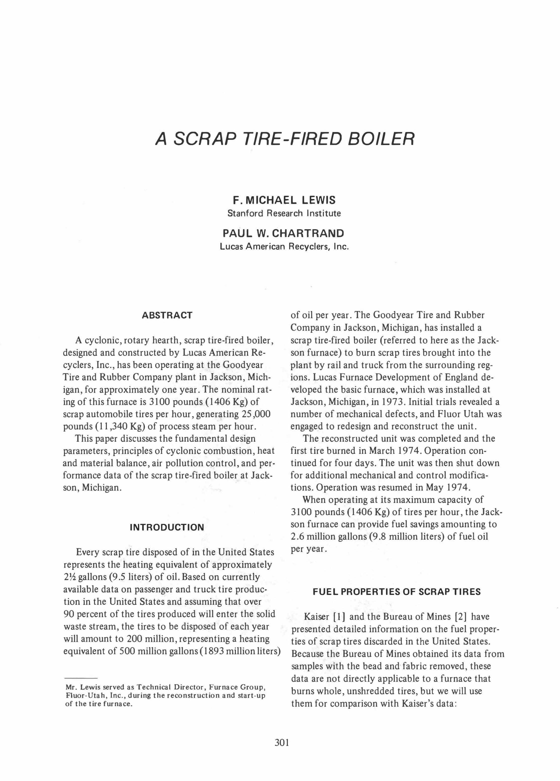
THE SCRAP TIRE FURNACE
The scrap tire furnace is a cyclonic, rotary hearth furnace. Figure 1 shows a cutaway view of a typical scrap tire furnace. A feeder located in an air-tight charging vestibule pushes the tires onto the outer edge of the rotating hearth. When the tire has completed its first revolution, the ash pusher moves the tire inward. After the tire has completed its second revolution, the action of the next tire being pushed into the inner burning ring pushes the remaining ash into the central ash discharge chute.
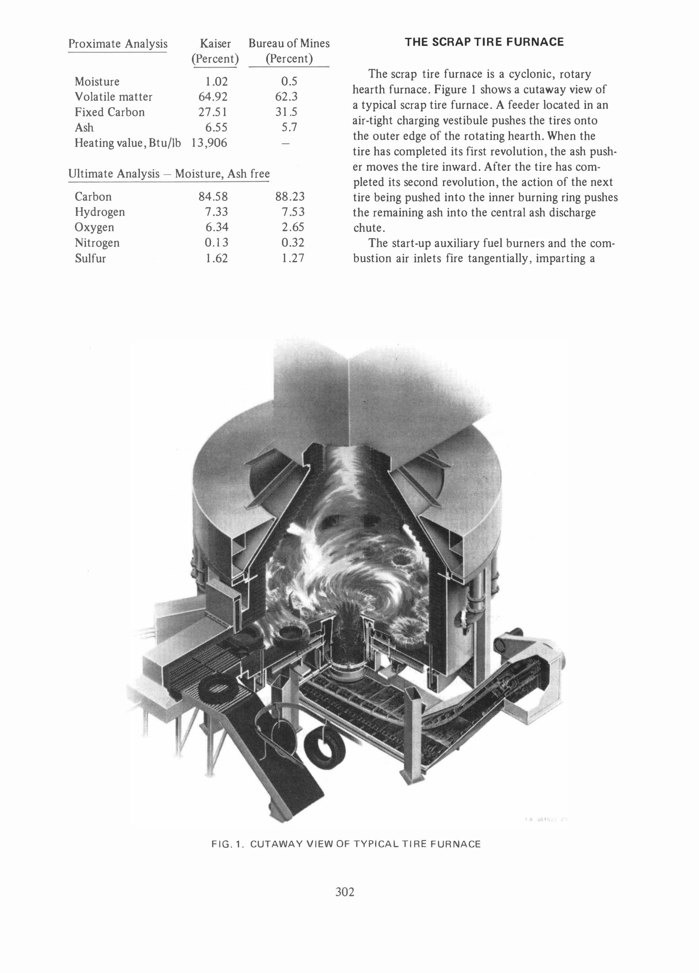
The start-up auxiliary fuel burners and the combustion air inlets fire tangentially, imparting a
FIG.1. CUTAWAY VIEW OF TYPICAL TIRE FURNACE
302
AUXILIARY FUEL
BURNER
TA-:Je1522-20
FIG.2. PLAN VIEW OF COMBUSTION AIR JETS AND BURNERS
, ,
,
I'
I ASH DISCHARGE
CHUTE �
INNER WATER
SEAL
ROTA TlNG HEARTH
/
OUTER WATER
SEAL
T A-361622-21
FIG.3. TYPICAL CROSS SECTION VIEW OF TIRE FURNACE
303

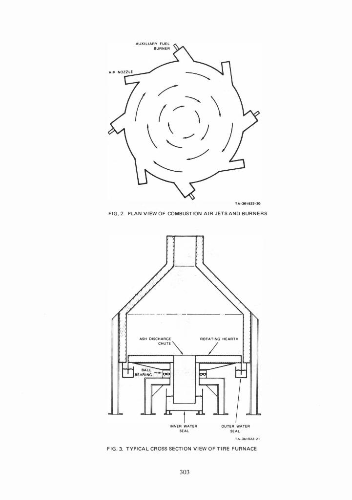
cyclonic swirl to the combustion gases. Figure 2 is a schematic view of the approximate location of the air jets and burners. Figure 3 shows a cross section of the inner and outer water seals of the Jackson furnace.
When the Jackson furnace is operating at the maximum design capacity of 3100 lb/hr ( l 406 Kg/hr), its heat release rate is 26,000 Btu/ft3 /hr (231,338 Kg-cal/m3 /hr), and the hearth loading is 214,000 BtU/ft2 /hr (580,449 Kg-cal/m2/hr).
A single ball bearing, with a double row of balls to take the thrust and shear loads, supports the rotating hearth. The bearing is similar to the bearings used on large cranes. The bearing assembly, with gear drive attached, is located underneath the hearth, requires no forced air or water cooling, and has easy access for maintenance. Supported from a
, ,
, ,
�
I �
•
� �
�
--•
� �
-
�� �
�
--.
,
, , , , , , , , , ,
, ,
central point underneath the refractory and hearth structure , the hearth is free to expand and thermal stresses are minimized.
The combination of the inner and outer water seals and the double door charging vestibule makes the furnace essentially gastight. All air for combustion enters the furnace through the tangential air jets.
CYCLONIC COMBUSTION IN
A ROTARY HEARTH
The inwardly moving solid fuel bed at the bottom' of the furnace and its relationship to the primary and secondary gas flows impart to the cyclonic, rotary hearth furnace combustion characteristics quite unique and quite different from those
' ,. , , , ,. , .. , ..
, , , , - - .
-
, , , ,
.. ..
� ,.
-
� �
-� \
, ,
- - - , ' . -------
'�� __ 4 __ _
T A-361522-17
FIG.4. CYCLONIC COMBUSTION GAS F LOW PATTERN
304

of other cyclonic and vortex combustion chambers. The secondary, recirculating gas flows , superimposed on the primary cyclonic flow (Figure 4), play a major role in the combustion process.
The Burea u of Mines [3,4] has developed a vortex incinerator with a solid feed and ash discharge system that differs from that of the Jackson furnace; however, temperature profiles and gas composition within the cyclonic flow pattern are similar. The Bureau of Mines data indicate that the cool combustion air in the vortex incinerator hugs the outer wall of the furnace and that a radial temperature profile exists , so that the flame is hottest at the vortex center. Under certain flow conditions, mixing between the solid fuel bed and combustion air in the vortex incinerator is so intense that all the oxygen is scavenged from the air before it reaches the center of the vortex. These principles of intense mixing and oxygen scavenging in the Bureau of Mines furnace are also important in a rotary hearth cyclonic furnace.
In the rotary hearth furnace , the absence of oxygen in the central region of the hearth creates an "aerodynamic pyrolysis zone." Heat is supplied to this region by radiation from the burning hot core of gases above the bed and from the surrounding brickwork. The residue discharged from this furnace resembles the black char obtained when a piece of rubber tire is pyrolyzed in an indirectly heated pyrolysis retort.
By viewing the central portion of the hearth from an outside view port , one can observe burning gases forming a tight core , similar in shape to a tornado, with its tip occasionally dipping down onto the top of the water surface in the central water seal. Because of the flicker of this rotating core of burning gases and some minor quantities of low fusion components in the tire that flow over the hearth, a common misunderstanding exists that the residue leaves the furnace as a molten slag.
When tires are first fed into the furnace and are on the outer portion of the hearth , the volatiles distill off very rapidly and are immediately swept toward the central, vertical burning core by the tangential combustion air. Combustion begins immediately in the tire region and continues as the gases go up the furnace core. Because of its small diameter and large surface area, the steel beadwire is oxidized as soon as it becomes exposed.
The carbon black used in the manufacture of tires burns very slowly because of its molecular structure, and a portion of this carbon remains when the residue is discharged into the residue
water seal. The lack of oxygen in the central region of the hearth also causes a small amount of carbonaceous char to form. This carbonaceous residue has some disadvantages:
a) Increased quantity of residue to be disposed of.
b) Loss of heating value because of the presence of combustibles in the residue.
It also has some advantages: a) Ease of residue handling; the residue handles
like a coarse sand. b) Elimination of the slagging problems caused
by high material temperatures that result when the fixed carbon burns.
c) Chemical binding of some potential pollutants to the carbonaceous portion of the char.
It is felt that the advantages outweigh the disadvantages.
305
OPERATION OF THE FURNACE SYSTEM
When operating at maximum capacity, the Jackson furnace will process 31 00 pounds (1406 Kg) of scrap tires per hour, equivalent to 43,400,000 Btu/hr (10,935,932 Kg-cal/hr). The weight of passenger tires varies with size and mileage but is approximately 25 pounds (11.3 Kg) per tire, resulting in a tire feed rate of 129 tires per hour, or 1,130,000 tires per year.
The tires are manually placed on a roller conveyor from the tire receiving area; all subsequent operations are automatic. The conveyor moves forward intermittently, in sequence with the tire feed rate. The tires are fed into the furnace from an airtight charging vestibule to minimize the danger of fires and air leaks into the furnace. On a Signal from the furnace temperature controller, the guillotine fire door on the furnace opens and the tire is pushed into the furnace. Because of the intense heat and radiation, the tire bursts instantly into flames. The tire begins a circular path through the furnace on the outer rim of the rotating hearth. Combustion of the volatiles is almost completed when the tire approaches the feed door at the end of its first revolution. An ash pusher located a few degrees upstream of the tire feeder pushes the tire into a second burning region, inside the outer circle of tires. The tire being pushed into this inner circle pushes the ashes from the tire previously occupying that area into the ash discharge chute. The ashes drop into the water seal and are discharged into a bin by an ash dredger.
The flue gases leave the furnace through a horizontal, approximately square breeching. The flue gasl!s are directed through a waste heat boiler with a retractable soot blower for the front tubes and two rotary soot blowers for the center tubes. The boiler exit gases then go to a wet scrubber. An induced draft fan provides the necessary draft for the system.
FLUID MECHANICS OF COMBUSTION
VORTEX
When the furnace was first put in operation, a proper combustion vortex could be obtained only at maximum capacity and with all the auxiliary fuel burners firing. The following analysis was performed to find out why and to take corrective action.
One of the three "I's" of combustion is turbulence. Currently, there is no satisfactory way to measure turbulence in a furnace. Horsepower (HP)/lb flue gas/sec (kW /Kg flue gas/sec) was chosen as the basic parameter to describe turbulence, because the turbulence is a measure of the power input to the system. The horsepower was determined by examining the power in the gas streams, the combustion air, and the burner flue products that entered the combustion chamber. From data obtained under good operating conditions for this furnace and other similar units, [4] it was determined that a value of 0.24 HP/lb flue gas/sec (0.39 kW/Kg flue gas/sec) gave the desired degree of turbulence, equivalent to a combustion air velocity head of approximately 2 inches (5.1 cm) water column.
The analysis was expanded to consider the furnace turbulence (HP/lb flue gas/sec) (kW/Kg flue gas/sec) input into the furnace as a function of combustion air jet diameter, mass flow rate, and jet temperature:
Let 1 denote initial conditions Let 2 denote final conditions Let D denote jet diameter, inches (meters) Let m denote mass flow rate, Ib/sec (Kg/sec) Let P denote furnace turbulence, HP/lb flue
gas/sec (kW /Kg flue gas/sec) Let T denote combustion air jet temperature,
°RCK) From a constant diameter jet with a varying
mass flow rate,
(1)
For a constant mass flow rate with varying jet diameter,
D1 D2
4
(2)
For a constant mass flow rate and jet diameter but with varying air jet temperature,
3
(3)
Examination of Equation (1) reveals that when a furnace of this type is run at partial load conditions, with the mass flow rate of combustion air reduced to, say, one third of the original flow rate, the furnace turbulence is reduced to one ninth of the original value.
Equation (3) demonstrates the effect of air preheat on the turbulence: if the initial temperature is 60°F (15 .6°C), the turbulence of the furnace can be doubled by heating the combustion air to only 195° F (90.6° C). If a turndown of 3: 1 is desired, the required air jet temperature to maintain the same degree of turbulence as the original 60°F (15 .6°C) jet would be 625°F (329AoC). , A design was considered that would use "choked flow" steam jets to maintain the turbulence constant. For the 250 psig (175,756 Kg/m2) saturated steam available at the site, a mass flow rate of 56 lb/hr (2504 Kg/hr) will give a 1 HP (0.75 kW) input. However, because turndown was not considered a major requirement, nozzles were never installed.
For many years, steam jets have been used to promote mixing in coal fired units, but no data are available on the fluid mechanics in terms of pounds of steam per horsepower and furnace turbulence.
HEAT AND MATERIAL BALANCE
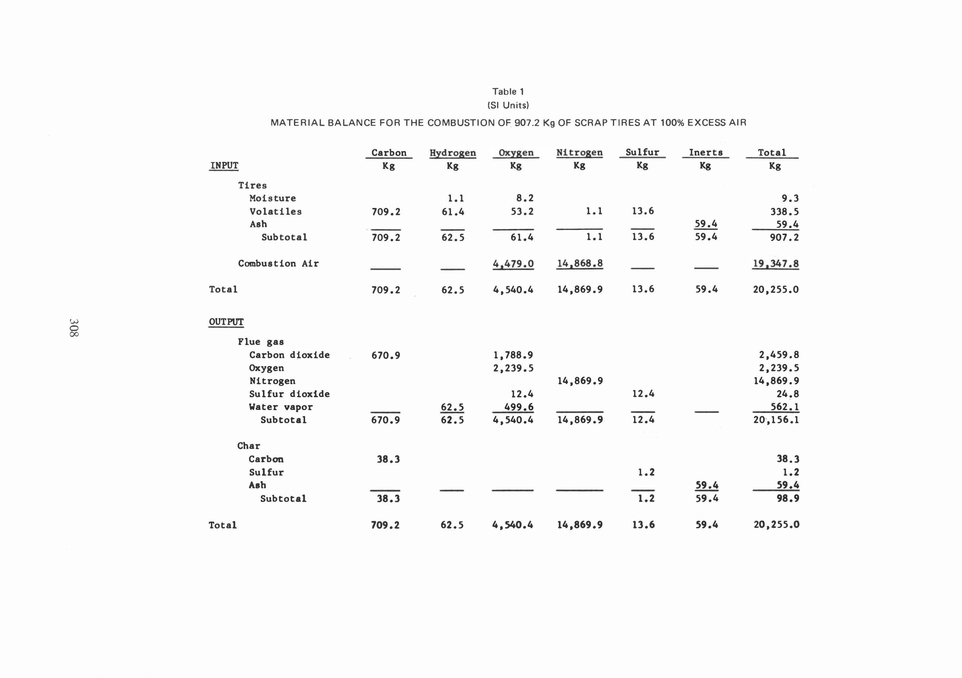
The tires are burned with approximately 100 percent excess air to keep the combustion temperatures below the point where furnace slagging would become a problem. The resultant flame temperature is approximately 2000°F (1 093°C). Table I
shows a material balance for the combustion of 2000 pounds (907.2 Kg) of tires at 100 percent excess air. Table 2 shows a heat balance for a boiler exhaust temperature of 500°F (260°C). Approximately 5 percent of the potential heat is lost because of the heating value of the char; however, this does prevent slagging of the ash.
The heat balance shown assumes zero heat loss. The boiler exit temperature chosen, 500°F (260°C),
306

w 0 -.l
Table 1
MATERIAL BALANCE FOR THE COMBUSTION OF 2000 LB SCRAP TIRES AT 100% EXCESS A IR
Carbon INPUT 1b
Tires Moisture Volatiles 1,563.6 Ash
Subtotal 1,563.6
Combustion air
Total 1,563.6
OUTPUT
Flue gas Carbon dioxide 1,479.0 Oxygen Nitrogen Sulfur dioxide Water vapor
Subtota1- 1,479.0
Char Carbon 84.6 Sulfur Ash
Subtotal 84.6
Total 1,563.6
Hydrogen Oxygen Nitrogen 1b 1b 1b
2.3 18.1 135.4 117.2 2.4
137.7 135.3 2.4
9,874.6 32,780.2
137.7 10,009.9 32,782.6
3,944.0 4,937.3
32,782.6 27.3
137.7 1,101.3 137.7 10,009.9 32,782.6
137.7 10,009.9 32,782.6
Sulfur Inerts 1b 1b
30.0 131.0
30.0 131.0
30.0 131.0
27.3
27.3
2.7 131.0
2.7 131.0
30.0 131.0
Total 1b
20.4 1,848.6
131.0 2,000.0
42,654.8
44,654.8
5,423.0 4,937.3
32,782.6 54.6
1,239.0 44,436.5
84.6 2.7
131.0 218.3
44,654.8
w 0 00
Table 1 (SI Units)
MATERIAL BALANCE FOR THE COMBUSTION OF 907.2 Kg OF SCRAP T IRES AT 100% EXCESS AIR
Carbon Hydrogen Oxygen Nitrogen Sulfur Inerts INPUT Kg Kg Kg Kg Kg Kg
Tires Moisture 1. 1 8.2 Volatiles 709.2 6 1.4 53.2 1. 1 13.6 Ash 59.4
-
Subtotal 709.2 62.5 6 1.4 1. 1 13.6 59.4
Combustion Air 4,479.0 14,868.8
Total 709.2 62.5 4,540.4 14,869.9 13.6 59.4
OUTPUT
Flue gas Carbon dioxide 670.9 1,788.9 Oxygen 2,239.5 Nitrogen 14,869.9 Sulfur dioxide 12.4 12.4 Water vapor 62.5 499.6
Subtotal 670.9 62.5 4,540.4 14,869.9 12.4
Char Carbon 38.3 Sulfur 1.2 Ash 59.4
-
Subtotal 38.3 1.2 59.4
Total 709.2 62.5 4,540.4 14,869.9 13.6 59.4
Total Kg
9.3 338.5
59.4 907.2
19,347.8
20,255.0
2,459.8 2,239.5
14,869.9 24.8
.
562. 1 20,156.1
38.3 1.2
59.4 98.9
20,255.0
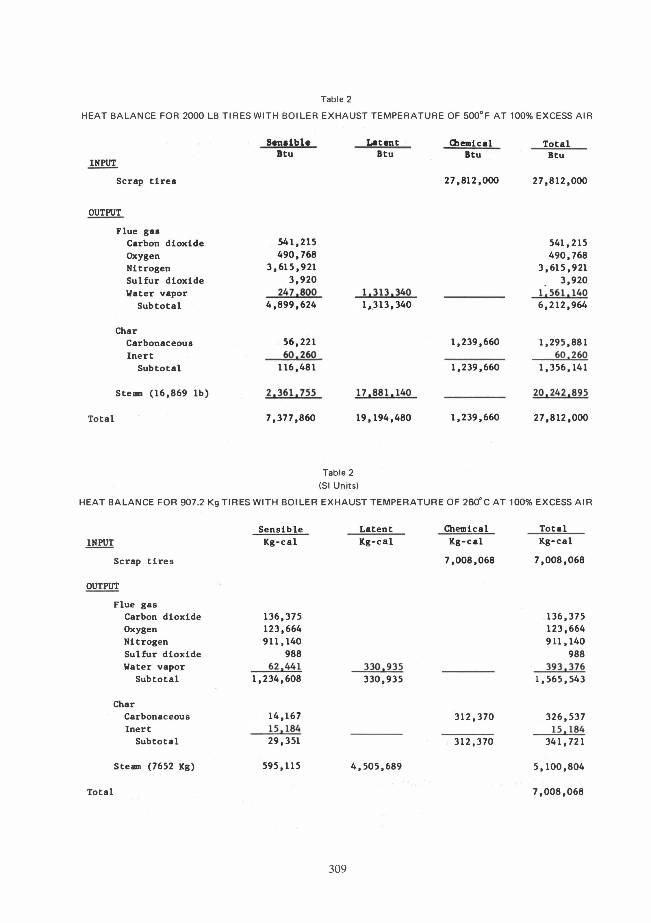
Table 2
HEAT BALANCE FOR 2000 LB TIRES WITH BOILER EXHAUST TEMPERATURE OF 500°F AT 100% EXCESS AIR
INPUT
Scrap tires
OUTPUT
Total
Flue gas Carbon dioxide Oxygen Nitrogen Sulfur dioxide Water vapor
Subtotal
Char Carbonaceous Inert
Subtotal
Steam ( 16,869 lb)
Senalble Btu
54 1,215 490,768
3,615,921 3,920
247.800 4,899,624
56,22 1 60.260
1 16,48 1
2,36 1,755
7,377,860
Latent Btu
1.3 13.340 1,3 13,340
17,88 1. 140
19, 194,480
Table 2
(SI Units)
at_ical Btu
27,812,000
1,239,660
1,239,660
1,239,660
Total Btu
27,8 12,000
541,2 15 490,768
3,615,921 3,920
•
1.56 1. 140 6,2 12,964
1,295,88 1 60,260
1,356, 14 1
20,242,895
27,8 12,000
HEAT BALANCE FOR 907.2 Kg TIRES WITH BOI LER EXHAUST TEMPERATURE OF 260°C AT 100% EXCESS AI R
IN,PUT
Scrap tires
OUTPut
Flue gas Carbon dioxide Oxygen Nitrogen Sulfur dioxide Water vapor
Subtotal
Char Carbonaceous Inert
Subtotal
Steam (7652 Kg)
Total
Sensible Kg-cal
136,375 123,664 9 1 1, 140
988 62.44 1
1,234,608
14,167 15,184 29,351
595, 1 15
309
Latent Kg-cal
330.935 330,935
4,505,689
Chemical Kg-cal
7,008,068
3 12,370
3 12,370
Total Kg-cal
7,008,068
136,375 123,664 911, 140
988 393,376
1,565,543
326,537 15,184
34 1,72 1
5, 100,804
7,008,068

EXHAUST STACK
FURNACE BOILER SCRUBBER 1.0 FAN
SAMPLE PORTS·
WET .
CYCLONES fA 361U
FIG. 5. SCHEMATIC DIAGRAM OF TIRE FURNACE SYSTEM
does not represent the condition at the Jackson furnace but rather, the minimum temperature that could be achieved in a practical system.
AIR POLLUTION CONTROL
Approximately 1-2 percent of the weight of a rubber tire is zinc oxide, which is used to impart certain desired properties to the rubber. Emission tests conducted upstream of any air pollution control device indicate that almost all the zinc oxide is carried out with the flue gas and exits as a submicron fume.
Actual measurements of furnace emissions indicate that a collection efficiency of 86 percent is needed to meet a typical emission code of 0.08 grains per standard dry cubic foot (183 mg/m3) at 12 percent carbon dioxide. Based on the "Contacting Power Concept" of scrubbers developed by Semrau [5] and data presented in that paper, a scrubber pressure drop of approximately 13 in. w.c. (33 cm) will be required.
Sulfur dioxide emission can be calculated directly from the sulfur content of the tires, although we believe that a tangible portion of the sulfur is concentrated in the char residue. The Bureau of Mines [2] data on the composition of char from pyrolysis of tires support this belief.
If a portion of the steam produced were to be used to provide the contacting power required for scrubbing - an extremely interesting possibility -the steam required for this furnace would represent approximately 5 percent of the potential steam production.
JACKSON FURNACE PERFORMANCE DATA
The actual capacity of the Jackson furnace exceeded the design capacity, and therefore, exceeded
310
the capacity of the boiler and scrubber. In June 1974, air pollution tests were conducted with the furnace running approximately 50 percent over design maximum; the excess flue gases were by-passed around the boiler and wet scrubber and taken through wetted wall cyclones. Figure 5 shows a schematic diagram of the system. These cyclones were large and of extremely low efficiency. The sprays did not saturate the gas and the exit temperature from the cyclones was approximately 700°F (371°C). The split of the gas flow was approximately 70 percent through the boiler and scrubbers and 30 percent through the cyclones. The unit did not pass the air pollution test because of the poor performance of the cyclones.
Additional tests, carried out in August 1974 with the furnace operating at design maximum, showed the unit to be in compliance with the State of Michigan Air Pollution Code for Boilers.
CONCLUSION
The rotary hearth furnace has proven an excellent design for the combustion of tires. The oxygendeficient region in the lower end of the central vortex has prevented refractory and material handling problems caused when ash is overheated and allowed to slag and clinker. The cool combustion air admitted along the periphery of the furnace has prevented damage to the refractory from the high combustion temperatures. The vortex of the flue gases above the fuel bed has provided a regime of stable and complete combustion.
The furnace has shown that it can burn tires at a rate significantly above design capacity. In future units, a bag house should be considered for particulate emission control and for potential recovery of the zinc oxide.

REFERENCES
[ 1] E. R. Kaiser, "The Incineration of Bulky Refuse," Proceedings of the 1966 National Incinerator Con
ference, ASME, New York, N.Y.
[2] D. E. Wolfson et aI., Destructive Distillation of Scrap
Tires, R I 7302 Bureau of Mines, U.S. Dept. of the Interior, September 1969.
[3] C. H. Schwartz et aI., "Development of a Vortex In-
cinerator with Continuous Feed," Proceedings of the
1972 National Incinerator Conference, ASME, New York, N.Y.
[4] M. Weintraub, A. A. Orning, C. H. Schwartz, Experi
mental Studies of Incineration in a Cylindrical Com
bustion Chamber, Bureau of Mines R I 6908, U.S. Dept. of the Interior, 1967.
[5] K. T. Semrau, "Dust Scrubber Design - A Critique on the State of the Art," J. APCA, Vol. 13, No. 12, pp. 587-594 (December 1963).
Key Words
Scrap Tire
Rubber
Heat recovery
Pyrolysis
Steam generation
Rotary hearth
Tires
Cyclonic
311