a servo controller for an mts machine midterm presentation david schwartz & uri goldfeld...
Post on 20-Dec-2015
216 views
TRANSCRIPT

A servo controllerA servo controllerfor an MTS machinefor an MTS machine
Midterm PresentationMidterm Presentation
David Schwartz & Uri goldfeld David Schwartz & Uri goldfeld
Supervisors : Supervisors :
Dany Alkalay & Amir ReovenDany Alkalay & Amir Reoven
Quick ReminderQuick Reminder
Project Goals:Project Goals:
Implementing a new control system for the Implementing a new control system for the MTS machine Located at the Material MTS machine Located at the Material Mechanics Laboratory.Mechanics Laboratory.
Replacing the current controller with the novel Replacing the current controller with the novel one. one.

Currently we have the old system with a built in controller:
We will replace the old controller using LabView:
FPGA LabView
We configure an FPGA NI board using LabView to replace the old controller
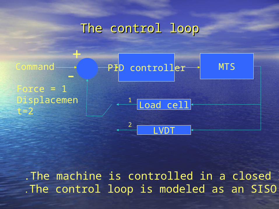
The control loopThe control loop
PID controller MTS+-
Command
LVDT
The machine is controlled in a closed loop.The control loop is modeled as an SISO LTI system.
Load cell1
2
Force = 1Displacement=2

Project stagesProject stages
Stage 1(Done)Stage 1(Done)::
System identification of the completeSystem identification of the complete system system
including the controllerincluding the controller
This stage was necessary in order to set a base This stage was necessary in order to set a base
line and see what is the required behavior of the line and see what is the required behavior of the
controlled system and to compare it to the system controlled system and to compare it to the system
behavior with our controller behavior with our controller

Stage 1’s stagesStage 1’s stages
• Learning LabView deeply Learning LabView deeply
• Learning MatLab System identification toolLearning MatLab System identification tool
• Finding the 3dB point of the systemFinding the 3dB point of the system• Finding Overshoot% and TFinding Overshoot% and Tsettling settling and Tand Trise_timerise_time
• Finding dominant poles (Finding dominant poles (W W n n and and ))
• Working with function generator while controlling Working with function generator while controlling it using LabViewit using LabView
• Finding Bode plot Gain + Phase of the systemFinding Bode plot Gain + Phase of the system

LabView
I/O card 6036
Agilent Waveform generatorAgilent Waveform generator
The measurement The measurement systemsystem
RS232RS232
MTSMTS
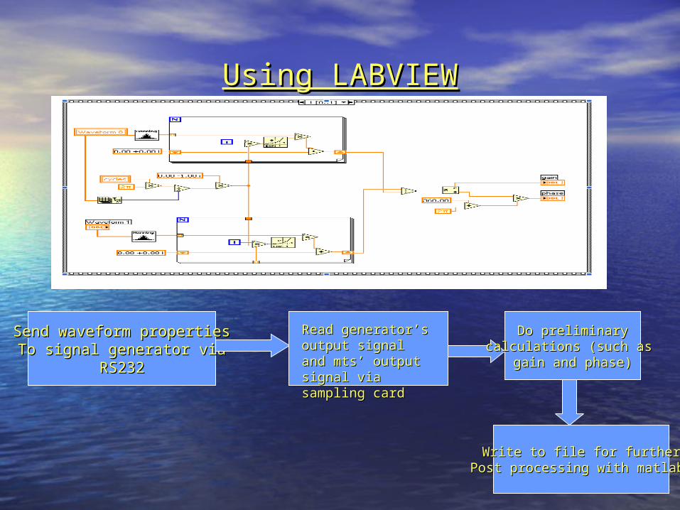
Using LABVIEWUsing LABVIEW
Send waveform propertiesSend waveform propertiesTo signal generator viaTo signal generator via
RS232RS232
Read generator’s Read generator’s output signal and output signal and mts’ output signal mts’ output signal via sampling cardvia sampling card
Do preliminaryDo preliminarycalculations (such as calculations (such as
gain and phase)gain and phase)
Write to file for furtherWrite to file for furtherPost processing with matlab Post processing with matlab

Stage 1’s details Stage 1’s details
• Finding the 3dB point of the system:Finding the 3dB point of the system: we used 2 techniques we used 2 techniques first: 3dB= Tfirst: 3dB= Trise_timerise_time/0.35 = 3.02Hz/0.35 = 3.02Hz second: inserting sin wave in up going Freq and second: inserting sin wave in up going Freq and
checking when the gain is 1/ sqrt(2) = 5.3Hzchecking when the gain is 1/ sqrt(2) = 5.3Hz
• Finding O.S% , TFinding O.S% , Tsettling settling and Tand Trise_timerise_time:: We made the proper VI that checks O.S and We made the proper VI that checks O.S and rise_time while in matlab we calculate Trise_time while in matlab we calculate Tsettlingsettling
We input a square wave and do all the testing on We input a square wave and do all the testing on the responsethe response
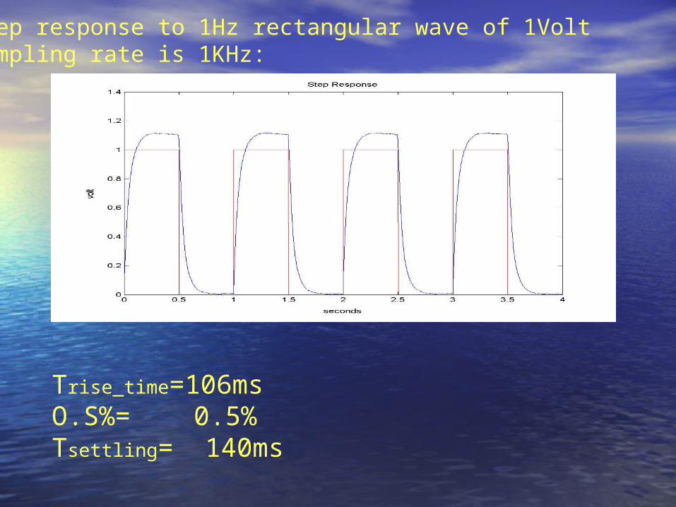
Step response to 1Hz rectangular wave of 1VoltSampling rate is 1KHz:
Trise_time=106msO.S%= 0.5%Tsettling= 140ms

• Finding dominant poles (Finding dominant poles (W W n n and and ):):
O.S% and TO.S% and Tsettlingsettling determine the dominant poles and determine the dominant poles and the poles came out:the poles came out:
critical dampcritical dampnn = = 33.765 33.765
2O.S.=exp - πζ 1-ζ =exp - π tgθ
2ln 0.05 1s
n
t
2
2 22n
n n
H ss s

• Finding Bode plot Gain + Phase of the systemFinding Bode plot Gain + Phase of the system
This was done with a VI that ran on Freq. This was done with a VI that ran on Freq. between 0.01Hz to 60Hz and sampling the between 0.01Hz to 60Hz and sampling the Gain and Phase for each Freq.Gain and Phase for each Freq.
GainGain
PhasePhase
• Stage 2(in progress now)Stage 2(in progress now)
doing system identification on the controller doing system identification on the controller himself and testing for his transfer function and himself and testing for his transfer function and other characteristics.other characteristics.
• Stage 3 Stage 3
after having the controller we will implement it in after having the controller we will implement it in LabView, Then replace the old controller with LabView, Then replace the old controller with ours and simulate the system with the LabView ours and simulate the system with the LabView controller. controller.

Time TableTime Table
DatesDates assignmentsassignmentsOn goingOn going Defining systems nominal requirements, interlocks Defining systems nominal requirements, interlocks
and limitations.and limitations.
Two-Three Two-Three weeksweeks
Building the controller in LabView using system Building the controller in LabView using system identification tools.identification tools.
One weekOne week Design a basic MTS servo system simulation in Design a basic MTS servo system simulation in LabView.LabView.
Two-Three Two-Three weeksweeks
Simulating our controller and comparing to previous Simulating our controller and comparing to previous full system full system
One weekOne week preliminary specifications of the experiment protocol preliminary specifications of the experiment protocol GUI.GUI.
One-Two weeksOne-Two weeks Project Book and final presentation for part BProject Book and final presentation for part B