a simple non-linear material model for pvc ... technet gmbh verseidag hightex gmbh formtl ferrari...
TRANSCRIPT
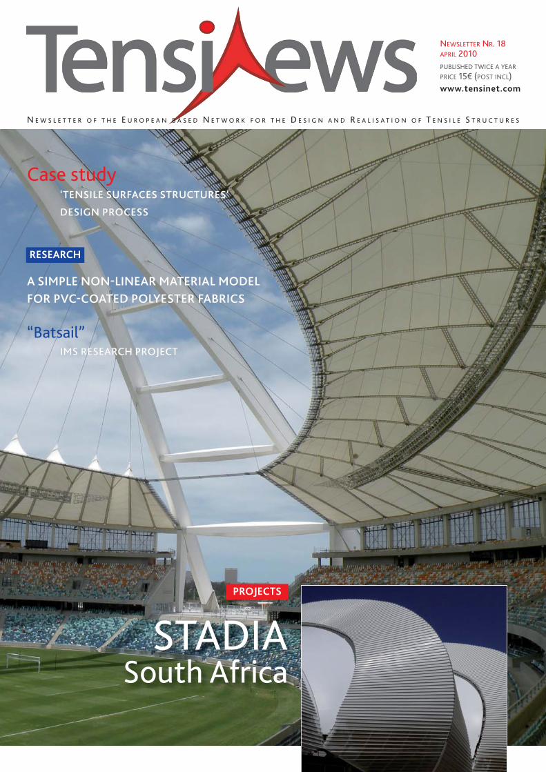
Case study‘TENSILE SURFACES STRUCTURES’
DESIGN PROCESS
A SIMPLE NON-LINEAR MATERIAL MODELFOR PVC-COATED POLYESTER FABRICS
“Batsail” IMS RESEARCH PROJECT
N E W S L E T T E R O F T H E E U R O P E A N B A S E D N E T W O R K F O R T H E D E S I G N A N D R E A L I S A T I O N O F T E N S I L E S T R U C T U R E S
NEWSLETTER NR. 18APRIL 2010PUBLISHED TWICE A YEARPRICE 15€ (POST INCL)www.tensinet.com
RESEARCH
PROJECTS
STADIASouth Africa
TENSINEWS NR. 18 – APRIL 20102
Ceno Tecwww.ceno-tec.de
Dyneonwww.dyneon.com
FabricArtMembrane Structureswww.fabricart.com.tr/
Form TLwww.Form-tl.de
Messe FrankfurtTechtextilwww.techtextil.de
Mehler Texnologies www.mehler-texnologies.com
Sioen Industries www.sioen.com
Saint-Gobain www.sheerfill.com
Taiyo Europewww.taiyo-europe.com
technet GmbHwww.technet-gmbh.com
Verseidagwww.vsindutex.de
Hightex GmbH www.hightexworld.com
form TL
Ferrari sawww.ferrari-textiles.com
Canobbio S.p.A.www.canobbio.com
partners2009
INFO
Buro Happoldwww.burohappold.com
PROJECTS
RESEARCH
ARTICLE
PA G E
23 VIENNE UNIVERSITY OF TECHNOLOGY MASTER PROGRAMMEMBRANE LIGHTWEIGHT STRUCTURES
ANHALT UNIVERSITY OF APPLIED SCIENCES MASTER COURSE MEMBRANE STRUCTURES
LITERATURE SPANISH EDITIONEuropean Design Guide for Tensile Surface Structures
THE TS ARCHI PROFILE PROFIL TENSION SYSTEM INNOVATION:
24 SYMPOSIUM TENSILE ARCHITECTURE Connecting Past & Future
MISC
n°18contents
Editorial BoardJohn Chilton, Evi Corne, Peter Gosling, Marijke Mollaert, Javier Tejera
CoordinationMarijke Mollaert, phone: +32 2 629 28 45, [email protected]
Address Vrije Uni ver siteit Brussel (VUB), Dept. of Architectural Engineering,Pleinlaan 2, 1050 Brus sels, Belgium fax: +32 2 629 28 41
ISSN1784-5688
All copyrights remain by each author
Price 15€ postage & packing included
PA G E
4 & 5 PakistanTOLL PLAZA CANOPIES
Spain LA FACTORIASun shading streets of the shopping mall
Turkey WEDDING HOUSE CANOPYA New Interpretation for the Wedding Gown
Turkey SPORT FACILITIES
8 > 13 South Africa 4 STADIUM PROJECTS
Johannesburg Soccer City StadiumDurban Moses Mabhida StadiumPort Elizabeth Stadium of the “windy city” Cape Town The new Cape Town Stadium
16 & 17 USA LONE BUTTE CASINO Lights Up the Desert Sky
Spain ETFE SINGLE SKINAranda de Duero ROOF
22 The NetherlandsJINSO PAVILION Extension to a catering pavilion
PA G E
6 & 7 A SIMPLE NON-LINEAR MATERIAL MODELfor PVC-coated polyester fabrics
14 “BATSAIL” IMS Research Project
15 FORMFINDER SOFTWARE"One Click" Cost Estimation for the architectural design of membrane structures
18 CASE STUDY ‘Tensile surfaces structures’ design process
TENSINEWS NR. 18 – APRIL 2010 3
Edito
TensiNet MeetingsVerseidag, Krefeld, Germany20/04/2010
Partner meeting 1 � 11:00 - 12:30Working Group ETFE � 13:30 - 15:30Working Group Analysis & Materials � 13:30 - 15:30
Location: VERSEIDAG-INDUTEX GmbHIndustriestraße 56 - D-47803 Krefeld
TensiNet Meetings, UACEG, Bulgaria TensiNet Symposium 201015/09/2010
Partner Meeting 2Annual General MeetingWorking Group Analysis & MaterialsWorking Group ETFEWorking Group Standardisation & Eurocode
Forthcoming Meetings
Forthcoming Meetings
TensiNet Meetings Verseidag, Krefeld, Germany20/04/2010
Partner meeting 1 � 11:00 - 12:30Working Group ETFE � 13:30 - 15:30Working Group Analysis
& Materials � 13:30 - 15:30
LocationVERSEIDAG-INDUTEX GmbHIndustriestraße 56D-47803 Krefeld
TensiNet Meetings UACEG, Bulgaria TensiNet Symposium 201015/09/2010
Partner Meeting 2Annual General MeetingWorking Group Analysis & MaterialsWorking Group ETFEWorking Group Standardisation &Eurocode
Forthcoming Events International exhibition ROOF INDIA 2010 Chennai Trade Centre, Chennai, India 23-25/04/2010
www.roofindia.com ● Workshop Textile Roofs 2010 TUB, Berlin, Germany 03-05/06/2010 www.textile-roofs.com ● 1st International
Conference on Structures and Architecture (ICSA 2010) University of Minho, Guimarães, Portugal 21- 23/07/2010 www.icsa2010.com
● Symposium 2010 Tensile Architecture: Connection Past and Future University of Architecture, Civil Engineering and Geodesy
16 - 18/09/2010 http://tensinet2010.uacg.bg / ● International Symposium on Spatial structures - Temporary and PermanentIASS 2010 Shanghai, China 08-12/11/2010 www.iass2010.cn ● International trade Fair & Symposium Techtextil 2011 Frankfurt, Germany
24 –26/05/2011 http://techtextil.messefrankfurt.com ● International conference on Structural Membranes 2011 Barcelona, Spain
05 –07/10/2011 http://congress.cimne.com/membranes2011/frontal/Dates.asp
TENSINEWS NR. 18 – APRIL 20104
MEHLER TEXNOLOGIES
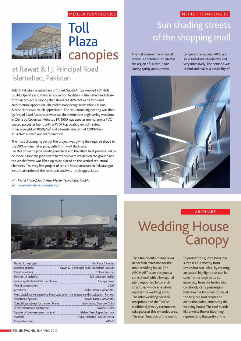
Tollink Pakistan, a subsidiary of Tollink South Africa, needed BOT-Toll(Build, Operate and Transfer) collection facilities in Islamabad and chosefor their project a canopy that stood out different in its form andarchitectural apparition. The preliminary design from Isbah Hassan & Associates was much appreciated. The structural engineering was done by Amjad Niazi Associates whereas the membrane engineering was donein China by Covertex. Mehatop FR 1000 was used as membrane: a PVCcoated polyester fabric with a PVDF top coating on both sides. It has a weight of 1050g/m² and a tensile strength of 120KN/m –110KN/m in warp and weft direction.
The most challenging part of the project was giving the required shape tothe 200mm diameter pipe, with 6mm wall thickness. For this project a pipe bending machine and the allied heat process had tobe made. Once the pipes were bent they were welded on the ground andthe whole frame was lifted up to be placed on the vertical structuralelements. The very first project of tensile fabric structure in Pakistan gotinstant attention of the architects and was much appreciated.
� Kashif Ahmed,South Asia, Mehler Texnologies GmbH� www.mehler-texnologies.com
Toll Plaza canopies
at Rawat & I.J. Principal Road Islamabad, Pakistan
Name of the project: Toll Plaza CanopiesLocation address: Rawat & I.J. Principal Road, Islamabad, Pakistan Client (investor): Tollink PakistanFunction of building: Toll collection facilityType of application of the membrane: Canopy CoverYear of construction: 2009 Architects: Isbah Hassan & AssociatesMulti disciplinary engineering, Main contractor, manufacture and installation: RamconStructural engineers: Amjad Niazi & AssociatesConsulting engineer for the membrane: Jason Wang, Covertex ChinaTensile membrane contractor: Covertex ChinaSupplier of the membrane material: Mehler Texnologies Germany Material: PVDF, Mehatop FR1000 Type IIICovered surface: 700m²
MEHLER TEXNOLOGIES
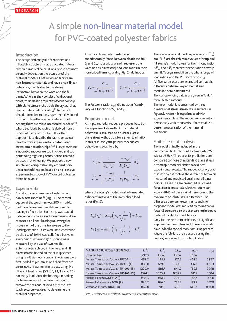
The first open-air commercialcentre La Factoria is situated inthe region of Huelva, Spain.During spring and summer
temperatures exceed 40°C andsolar radiation hits directly andvery intensively. The demand wasto find and realize a possibility of
Sun shading streetsof the shopping mall
Wedding HouseCanopy
ARCH-ART
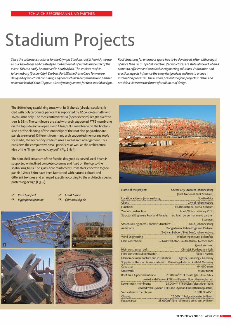
The Municipality of Karşıyakaneeded an extension for themain wedding house. TheARCH-ART team designed aconical roof with a hexagonalplan, supported by six archstructures which as a wholerepresent a wedding gown. The after wedding cocktailreceptions and the Turkishtraditional jewelry ceremoniestake place at this extended area.The main function of the roof is
to protect the guests from rainsurprises but mostly fromIzmir’s hot sun. Also, by creatingan optical highlight that can beseen from a large distance,especially from the ferries thatconstantly carry passengersbetween the two main zones ofthe bay; the roof creates anattraction point, enhancing thewedding house. The roof standslike a white flower blooming,representing the purity of the
TENSINEWS NR. 18 – APRIL 2010 5
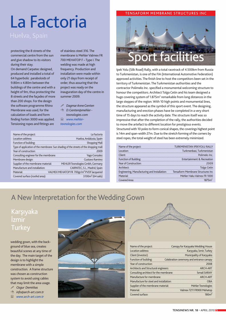
Ipek Yolu (Silk Road) Rally, with a total racetrack of 4.500km from Russiato Turkmenistan, is one of the FIA (International Automotive Federation)approved activities. The finish line to host the competitors been set in theterritory of Turkmenistan. The Turkmenistan authorities and thecontractor Polimeks Inc. specified a monumental welcoming structure tohonour the competitors. Architect Tolga Cetin and his team designed ahuge covering system of 1.875m2 remarkable from long distances in thelarge steppes of the region. With 10 high points and monumental lines,the structure appeared as the symbol of this sport event. The designing,manufacturing and erection phases have be completed in a very shorttime of 15 days to reach the activity date. The structure itself was soimpressive that after the completion of the rally, the authorities decidedto move the artefact to different location for prestigious events. Structured with 10 poles to form conical shapes, the coverings highest pointis 14m and span-width 27m. Due to the stretch forming of the corners bysteel ropes, the total weight of steel has been extremely minimized.
Sport facilities
Name of the project: TURKMENISTAN IPEKYOLU RALLYLocation: Turkmenbasi, TurkmenistanClient: Polimeks Inc.Function of Building: Entertainment & RecreationYear of Construction: 2009Architect: Tolga CetinEngineering, Manufacturing and Installation: Tensaform Membrane Structures IncMaterial: Mehler Haku Valmex FR 1000Covered Area: 1875m2
protecting the 8 streets of thecommercial centre from the sunand give shadow to its visitorsduring their stay.On demand Carpatec designed,produced and installed a total of64 hyperbolic paraboloids of9.80m x 4.80m between thebuildings of the centre and with aheight of 9m, thus protecting the8 streets and the façades of morethan 200 shops. For the designthe software programme RhinoMembrane was used, for thecalculation of loads and formfinding Forten 3000 was applied.Tensioning ropes and fittings are
of stainless steel 316. Themembrane is Mehler Valmex FR700 MEHATOP F – Type I. Thewelding was made at highfrequency. Production andinstallation were made withinonly 21 days from receipt oforder, thus assuring that theproject was ready on theinauguration day of the centre insummer 2009.
� Dagmar Anne Genten� D.Genten@mehler -
texnologies.com� www.mehler-texnologies.com
Name of the project: La Factoria Location address: Huelva, Andalusia, Spain Function of building: Shopping Mall Type of application of the membrane: Sun shading of the streets of the shopping mall Year of construction: 2009 Consulting engineer for the membrane: Yago Gonzalez Membrane design: Gustavo RamirezSupplier of the membrane material: MEHLER Texnologies Gmbh, Germany Manufacture and installation: CARPATEC, S.L., Madrid, Spain Material: VALMEX MEHATOP FR 700gr/m² PVDF lacqueredCovered surface (roofed area): 3.100m² (64 sails)
La Factoria
Name of the project: Canopy for Karşıyaka Wedding HouseLocation address: Karşıyaka, İzmir, TurkeyClient (investor): Municipality of KarşıyakaFunction of building: Celebration ceremony and entrance canopyYear of construction: 2008Architects and Structural engineers: ARCH-ART Consulting architect for the membrane: İsmail SARIAYManufacture for membrane: ARCH-ARTManufacture for steel and installation: OBASupplier of the membrane material: Mehler TexnologiesMaterial: Valmex 7211 FR900 MehatopCovered surface: 180m²
KarşıyakaİzmirTurkey
wedding gown, with the back -ground of blue sea, createsbeautiful scenes at any time ofthe day. The main target of thedesign is to highlight themembrane with a simpleconstruction. A frame structurewas chosen as constructionsystem to avoid using cablesthat may limit the area usage.� Ozgur Demirbas� [email protected]� www.arch-art.com.tr
A New Interpretation for the Wedding Gown
TENSAFORM MEMBRANE STRUCTURES INC
TENSINEWS NR. 18 – APRIL 2010
RESEARCH
6
IntroductionThe design and analysis of tensioned andinflatable structures made of coated-fabricsrely on numerical calculations whose accuracystrongly depends on the accuracy of thematerial models. Coated woven fabrics arenon-isotropic materials and have a non-linearbehaviour, mainly due to the stronginteraction between the warp and the fillyarns. Whereas they consist of orthogonalfibres, their elastic properties do not complywith plane stress orthotropic theory, as it hasbeen emphasized by Gosling [1]. In the lastdecade, complex models have been developedin order to take these effects into account.Among them are micro-mechanical models [2, 3],where the fabric behaviour is derived from amodel of its microstructure. The otherapproach is to describe the fabric behaviourdirectly from experimentally determinedstress-strain relationships [4, 5]. However, theseelaborated models are too involved and toodemanding regarding computation times tobe used in engineering. We propose a newsimple and computationally efficient non-linear material model based on an extensiveexperimental study of PVC-coated polyesterfabric behaviour.
ExperimentsCruciform specimens were loaded on ourbiaxial test machine [6] (Fig. 1). The centralsquare of the specimen was 500mm wide. Ineach cruciform arm four slits were madeleading to five strips. Each strip was loadedindependently by an electromechanical drivemounted on linear bearings allowing freemovement of the drive transverse to theloading direction. Tests were load-controlledby the use of 10kN load cells fixed betweenevery pair of drive and grip. Strains weremeasured by the use of two needle-extensometers placed in the warp and filldirection and bolted on the test specimenusing small diameter screws. Specimens werefirst loaded at pre-stress and then from pre-stress up to maximum test stress using fivedifferent load ratios (5:1, 2:1, 1:1, 1:2 and 1:5).For every load ratio, the loading/unloadingcycle was repeated five times in order toremove the residual strains. Only the lastloading curve was used to determine thematerial properties.
An almost linear relationship wasexperimentally found between elastic moduliEf and Ew (subscripts w and f represent thewarp and fill directions) and load ratios in theirnormalized form γw and γf (Fig. 2), defined as
The Poisson’s ratio νwf did not significantlyvary as a function of γw and γf..
Proposed modelA simple material model is proposed based onthe experimental results [7]. The materialbehaviour is assumed to be linear elastic,plane stress orthotropic for a given load ratio.In this case, the yarn-parallel mechanicalbehaviour is described by
where the Young’s moduli can be formulatedas linear functions of the normalized loadratios (Fig. 2):
The material model has five parameters: Ε 1:1w
and Ε 1:1f are the reference values of warp and
fill Young’s moduli given for the 1:1 load ratio,ΔΕw and ΔΕf represent the variation of warpand fill Young’s moduli on the whole range ofload ratios, and the Poisson’s ratio νwf. All five parameters are estimated so that thedifference between experimental andmodelled data is minimized. The corresponding values are given in Table 1for all tested materials.The new model is represented by threedimensional stress-stress-strain surfaces inFigure 3, where it is superimposed withexperimental data. The model non-linearity ishere clearly visible: curved surfaces enable abetter representation of the materialbehaviour.
Finite element analysisThe model is finally included in thecommercial finite element software ANSYSwith a USERMAT routine. Its predictions arecompared to those of a standard plane stressorthotropic material and to biaxial testexperimental results. The model accuracy wasassessed by estimating the difference betweenmeasured and predicted strains for all datapoints. The results are presented in Figure 4for all tested materials with the root meansquare (RMS) of the strain difference and themaximum absolute strain difference. Thedifference between experiments and theproposed model was reduced by more than afactor 2 compared to the standard orthotropicmaterial model for most fabrics. Only for the Ferrari membranes no significantimprovement was observed. These materialshave indeed a special manufacturing processwhere the fabric is pre-stressed during thecoating. As a result the material is less
A simple non-linear material model for PVC-coated polyester fabrics
σ wγw =
σ 2w + σ 2f
σ fγw =
σ 2w + σ 2f
1 − νwfεw = σwΕw(γw) Εw(γw)
− νwf 1εf = σfΕw(γw) Εf (γf)
1Εw(γw) = ΔΕw(γw − ) + Ε 1:1
w2
1 Εf (γf) = ΔΕf (γf − ) + Ε 1:1
f2
MANUFACTURER & REFERENCE Ε 1:1w Ε 1:1
f ΔΕw ΔΕf νwf(polyester type) (kN/m) (kN/m) (kN/m) (kN/m)
MEHLER TEXNOLOGIES VALMEX FR700 (I) 653.2 444.5 521.2 403.7 0.327MEHLER TEXNOLOGIES VALMEX FR900 (II) 882.0 679.6 803.8 437.6 0.263MEHLER TEXNOLOGIES VALMEX FR1000 (III) 1200.0 881.7 941.2 782.5 0.318MEHLER TEXNOLOGIES VALMEX FR1400 (IV) 1374.1 1003.4 1204.7 981.7 0.314FERRARI PRÉCONTRAINT 702 (I) 635.3 661.9 295.0 168.5 0.196FERRARI PRÉCONTRAINT 1002 (II) 830.2 976.0 766.7 123.9 0.213VERSEIDAG INDUTEX B1617 (II) 865.8 707.5 662.9 662.5 0.308
Table 1. Estimated parameters for the proposed non-linear material model.

TENSINEWS NR. 18 – APRIL 2010 7
sensitive to crimp interchange and itsbehaviour is similar to a standard linearorthotropic material. The second importantresult is that the computation time did notsignificantly increase. An average increase ofless than 3% was observed during theanalyses.
ConclusionA simple non-linear material model todescribe the yarn parallel behaviour of PVC-coated polyester fabrics under biaxial tensionhas been proposed. The model is based on a
standard plane stress orthotropic materialmodel with a constant Poisson’s ratio but withYoung’s moduli that are linear functions of thenormalized load ratios. The material responsecan be accurately described with fiveparameters, namely the warp and fill Young’smoduli for a 1:1 load ratio, the change in warpand fill Young’s moduli and the Poisson’s ratio.Only five different load ratios have to bemeasured in order to obtain reliableparameters. The new model has been includedin ANSYS with a USERMAT routine. It hasalready successfully been applied for the finite
element analysis of Tensairity® inflatedstructures developed in our centre [8]. The model is also suitable for the design oftensile fabric structures, where it could helpimproving the accuracy of numericalpredictions.
� Dr. Cédric Galliot� Dr. Rolf Luchsinger� [email protected]� [email protected]� www.empa.ch/css
(Center for Synergetic Structures)
Figure 1. Biaxial testing machine.
Figure 2. Linear relationship between Young’s moduliand normalized load ratios.
Figure 3. Stress-stress-strain representation ofexperimental data (red lines) and prediction of theproposed non-linear model (blue grid).
Figure 4. Comparison between the proposed non-linearmodel with a linear elastic orthotropic material model:difference between FEA predictions and experimentalresults.
RESEARCH
1 1
2
3
4
REFERENCES[1] Gosling PD. Tensinet analysis & materials working group – Basic philosophy and calling notice. Tensinews Newsletter 2007;13:12-15.[2] Pargana JB, Lloyd-Smith D, Izzuddin BA. Advanced material model for coated fabrics used in tensioned fabric structures. Engineering Structures 2007;29:1323-1336.[3] Cavallaro PV, Johnson ME, Sadegh AM. Mechanics of plain-woven fabrics for inflated structures. Composite Structures 2003;61:375-393.[4] Minami H. A multi-step approximation method for nonlinear analysis of stress and deformation of coated plain-weave fabric. Journal of Textile Engineering
2006;52(5):189-195.[5] Bridgens BN, Gosling PD. Direct stress-strain representation for coated woven fabrics. Computer & Structures 2004;82:1913-1927.[6] Blum R, Bögner H. A new class of biaxial machine. Tensinews Newsletter 2001;1:4.[7] Galliot C, Luchsinger RH. A simple model describing the non-linear biaxial tensile behaviour of PVC-coated polyester fabrics for use in finite element analysis.
Composite Structures 2009;90(4):438-447.[8] Galliot C, Luchsinger RH. Biaxial tensile testing and non-linear modelling of PVC-coated polyester fabrics for use in Tensairity girders. In: Kröplin B, Oñate E, editors.
International Conference on Textile Composites and Inflatable Structures, Structural Membranes 2009. CIMNE: Barcelona, 2009.

TENSINEWS NR. 18 – APRIL 20108
4South Africa’s successful application for hosting the World Cup has resultedin the construction of several new stadia. The construction or modernizationof these new arenas coincides with novel ideas for the design. In all cases theroofs play the major role when it comes to the question of unique design andeasy recognition. The roof is the most important element to create thestadium look.
The earth coloured ‘African Pot’, the traditional calabash, as a melting pot of cultures can be seen as the unique Pan-African symbol (Fig. 1). This was the main idea of the architects for the design of the biggest stadium on the African continent.
The stadium can accommodate 94.000 spectators. The three tier levelscan be reached via curved inner and outer ramps. The Stadium is locatedin close neighbourhood to Soweto. Historical parts of the upper tier levelof the old stadium (built in 1987), where Nelson Mandela was presentduring important events have been retained and conserved, whereas thewhole rest of the stadium has been newly built. Specially arranged coloured façade-panels with 6 colours and 3 textureson the surface changing from darker to lighter colours on the top as well asthe light coloured upper membrane blend into the natural surroundings ofthe typical local ‘mine-dumps’. Starting from the architects images andideas, schlaich bergermann und partner designed and developed theoptimised structure for the huge roof and the façade structure in closecorporation with the structural engineers of the concrete tiers structure,
PDNA of Johannesburg. The overall shellgeometry (roof and façade) derives from a toruswith an outer diameter of 300m which wasdefined in section with varying radiuses (Fig. 2).
As the opening of the roof and the surrounding spatial ring truss (themost important structural element) follow the rectangular shape of thefield and the arrangement of the tiers, both geometries combined createan impressing 3-dimensional curved structure.
Figure 1: Arial view of the stadium.
Figure 2. Plan.
Figure 3. Construction details.
Figure 4. Erection of the roof.
Figure 5. Erection of the facade.
© PDNA
2
2 3 3
3
South African Johannesburg
Durban
Port Elizabeth
Cape Town
Soccer City StadiumJohannesburg
1
TENSINEWS NR. 18 – APRIL 2010 9
SCHLAICH BERGERMANN UND PARTNER
Since the cable net structures for the Olympic Stadium roof in Munich, we useall our knowledge and creativity to make the roof of a stadium the star of theevent. This can easily be observed in South Africa. The stadium roofs inJohannesburg (Soccer City), Durban, Port Elizabeth and Cape Town weredesigned by structural consulting engineers schlaich bergermann und partnerunder the lead of Knut Göppert, already widely known for their special designs.
Roof structures for enormous spans had to be developed, often with a depthof more than 50 m. Spatial load transfer structures are state of the art when itcomes to efficient and sustainable engineering solutions. Fabrication anderection aspects influence the early design ideas and lead to uniqueinstallation processes. The authors present the four projects in detail andprovide a view into the future of stadium roof design.
The 800m long spatial ring truss with its 3 chords (circular sections) isclad with polycarbonate panels. It is supported by 12 concrete shafts and16 columns only. The roof cantilever truss (open sections) length over thetiers is 38m. The cantilevers are clad with arch supported PTFE membraneon the top side and an open mesh Glass/PTFE membrane on the bottomside. For the cladding of the inner edge of the roof also polycarbonatepanels were used. Different from many arch supported membrane roofsfor stadia, the soccer city stadium uses a radial arch arrangement. Thisconsiders the comparative small panel size as well as the architecturalidea of the “finger formed clay pot” (Fig. 3 & 4).
The slim shell structure of the façade, designed as curved steel beam issupported on inclined concrete columns and fixed on the top to thespatial ring truss. The glass-fibre reinforced 13mm thick concrete façadepanels 1,2m x 3,6m have been fabricated with natural colours anddifferent textures and arranged exactly according to the architects specialpatterning design (Fig. 5).
Name of the project: Soccer City Stadium Johannesburg (First National Bank Stadium)
Location address: Johannesburg, South AfricaClient: City of JohannesburgFunction: Multifunctional arena, StadiumYear of construction: April 2006 – February 2010Structural Engineers Roof and Facade: schlaich bergermann und partner,
StuttgartStructural Engineers Concrete Structure: PDNA, JohannesburgArchitects: Boogertman, Urban Edge and Partners
(Bob van Bebber / Piet Boer), JohannesburgWind Engineering: Wacker Ingenieure, BirkenfeldMain contractor: GLTA/Interbeton, South Africa / Netherlands
(Joint Venture)Main contractor roof: Cimolai, Pordenone / ItalyFibre concrete subcontractor: Rieder, AustriaMembrane manufacture and installation: Hightex, Rimsting / Germany Supplier of the membrane material: Verseidag-Indutex, Krefeld, GermanyCapacity: 94.000 seatsSteelwork: 9.000 tonneRoof area: Upper membrane: 23.000m² PTFE/Glass (glass fiber fabric
coated with Dyneon PTFE and Dyneon Fluorothermoplastics)Lower mesh membrane: 25.000m² PTFE/Glass(glass fiber fabric
coated with Dyneon PTFE and Dyneon Fluorothermoplastics)Vertical mesh membrane: 2.000 PES/PVCGlazing: 12.000m² Polycarbonate, t=12mmFacade area: 35.000m² fibre reinforced concrete, t=13mm
� Knut Göppert� [email protected]
� Frank Simon � [email protected]
4 5
4 55
Stadium Projects

As part of the City of Durban´sredevelopment program theprojected World Cup stadium waschosen to create an icon for theKwaZulu Natal region andDurban, being the 2nd largest cityin South Africa. The ambitiousplan to gain internationalattention enabled the leadArchitects von Gerkan Marg undPartner, Berlin, the lead structuralengineers schlaich bergermannund partner, Stuttgart and BKS,Durban to design an outstandingstadium of unprecedented scaleand beauty and therefore wonthe design competition. Thescope of work for the structuralengineers did also include allerection engineering, thechecking of all workshopdrawings and surveys, the siteand fabrication supervision aswell as the technical lead for thetender process and the imple -mentation phase for the client.
The multipurpose stadium with apossible capacity of 85.000 seatsfeatures a unique roof structureof 46.000m² of Glass/PTFEmembrane being prestressedagainst a cable net. The cable netis tensioned against two steelcompression rings along theperimeter of the stadium and amayor arch structure with 103mheight and 360m distance be -tween its foundations (Fig. 2- 3).Governed by the high wind loadsin close proximity to Durban´scoastline the membranestructure required a rather densecable support structure tominimize the membrane stresses.To achieve a global safety factorgreater than 5, as stipulated inthe European design guide fortensile surface structures, thedistance in plan between ridgeand valley cables needed to bereduced to a maximum distanceof only 8m at the outside
perimeter (compression ring).Often the installation proceduresreduce the material strengthremarkably, especially wheneffective quality control ismissing. To achieve the requiredsafety factor in reality, a detailedinvestigation into the strengthdeterioration due to, manu fac tu -ring, handling, packing andinstallation was undertaken, toovercome the critical strengthreduction due to folding of theglass/PTFE material. In order tonot accept mishandling of thematerial the braking strength ofthe virgin material and thehandled material was comparedin several stages, even by takingout installed sub panels fortesting. The form found andmost effective structural shape ofthe stadium roof drains 75% ofthe rain water directly towardsthe gutter located at thecompression ring.
The remaining water is firstlyrunning towards the tension ring,before it can be redirectednaturally towards the com pres -sion ring in the areas underneathto the arches. To achieve this themembrane shape and the gutterlocated on the tension ring had tobe form found in a specificmanner. All membrane connec -tions close to the gutter wereconnected using continuouscables and cable clamps requiringlocal membrane cut outs withunsupported membrane edges.These locations were designedand tested using bias cut andstraight cut membranes. Theinstallation of the membranepanels was following structuraldesign criteria that were derivedusing the local wind data ofprevailing winds. Due to the openshape of the partly installed roofthe wind loads during construc -tion and therefore membranestresses were higher than for thefinal building, even thoughreduced wind pressures forconstruction stages were used.Several construction stages, alsofor the membrane installation,had to be assessed in the windtunnel.
� Knut Göppert� [email protected]
� Markus Balz � [email protected]
Figure 1. Arial view of the stadium. Figure 2. Equilibrium of tension andcompression forces. Figure 3. Erection of the mayor arch structureand final interior view.
TENSINEWS NR. 18 – APRIL 201010
Name of the project: Moses Mabhida Stadium, DurbanLocation address: Durban, South AfricaClient: City of Durban - eThekwini MunicipalityFunction: stadiumYear of construction: March 2006 – November 2009Structural Engineers Roof: schlaich bergermann und partner, StuttgartStructural Engineers Concrete Structure: BKS Durban, South AfricaArchitects: gmp Architekten, BerlinConsulting engineer for the membrane: Birdair, BuffaloWind Engineering: Wacker Ingenieure, BirkenfeldMain contractor: JV WBHO / Group 5Main contractor Roof: Pfeifer Seil- und Hebetechnik, MemmingenMembrane subcontractor: Birdair, BuffaloSupplier of the membrane material: Saint Gobain, Merrimack, NHCapacity: 70.000 World Cup mode; 54.000 legacy temporary seats will
be substituted by conference facilities; 85.000 Olympic modeSteel work: 2.860 tonne main arch,
2.700 tonne compression ring and columnsCable structure: 550 tonneMembrane surface: 46.000m²Roof area: 39.000m² (vertical projection)
2 2
3 3
Durban
Moses Mabhida Stadium1
TENSINEWS NR. 18 – APRIL 2010 11
Port Elizabeth, one of the South African cities selected to host the games of2010 Fifa World Cup had the special challenge of building a world classsports arena. A German design team started in 2005 the planning of thestadium, aiming to design a signature landmark that could be at the sametime a structurally and economically meaningful building.Contractors from South Africa, USA, Australia, Japan and Kuwait workedduring 42 months in its construction, until its completion in April 2009.Particular boundary conditions, as the frequent wind and an extremelycorrosive environment, due to high temperatures combined with a highdegree of humidity and salt content of the air required individual solutionsfrom the very initial design of the roof until its final completion.The architectural planning team was inspired by the privileged site, anelevated platform next to the North End Lake, to create a building thatcould be remarkable and visible from afar.Roof and facade had a fundamental role in the planning process –integrated in an interesting interplay of concave and convexes forms, both created not only the stadium identification, but functionally they also provided a wind shelter for the internal stands. In addition to thewind tunnel tests to determine the wind loads acting onto the roof, a windcomfort study for the stands and the field was performed to provide themaximal comfort to the spectators as well as the owner’s confidence in theproject. Again, schlaich bergermann und partner’s approach to control allstages of a project, from first design ideas until the last bolt being placed,was a fundamental contribution to the success of the project. Thirty-sixtriple chord steel girders of spatial tubular framework, cantilevering overthe grandstands, carry the roof and simultaneously articulate the uniqueouter appearance of the stadium like petals of a flower growing on top ofmonumental facade columns and tapering off towards the centre of the
stadium, all together forming a calyx in a ridge and valley shape (Fig. 2).The girders, clad with aluminium standing seam sheeting, form the ridges.Fabric panels of PTFE coated glass fibre membrane, spanning between thegirders, form the valleys and dewater the roof. The alternation oftranslucent and opaque material is visible as a series of illuminatedsurfaces: at day from inside - at night from outside. A ring beam connectingthe top points of the girders forms the inner edge of the membrane baysand carries a circular walkway integrating the flood light system (Fig. 3).Polysyloxane based corrosion protection with high UV resistance has beenchosen for the structural steelwork; movable and accessible parts areduplex coated. All relevant details of connections of the membrane and thealuminium sheeting had to pass a long term salt spray test to demonstratetheir applicability. Port Elizabeth stadium construction performed aninteresting experience in the coordination of international suppliers andcontractors, in a complex but successful example of globalisation. The steelframework girders were prefabricated in Kuwait and shipped to PortElizabeth in parts. Next to the bowl, the girders were assembled onfalse-work templates considering tight tolerances. After surveying, the 45mlong 25m wide curved 55 tonne trusses were lifted in position on top of theR/C structure by a crawler crane. Due to a maximum wind speed for thecrane activity, most lifts had to be done in the early morning hours and hadto be finished before the wind frequently started to increase. Themembrane panels, fabricated in Japan, were unfurled on a temporary netspanning between the girders and pre-tensioned in steps. A big part of thealuminium sheeting has been installed by climbers sheet by sheet sinceonly the area next to the facade was accessible by a movable shoring tower.Besides accommodating sports events like a 2010 quarter final, the stadiumalso houses conference rooms, offices, gastronomy and corporate boxes.The major legacy of Port Elizabeth stadium is, therefore, its remarkablecontribution to the revitalization of the quarters around North End Lake,transforming the area with its architectural presence and opening its doorsfor the public, even beyond the final whistle of the 3rd place playoff matchin South Africa this year.
Port Elizabeth
Stadium of the “windy city”
Name of the project:The roof for the new 2010 WorldCup Stadium, Port ElizabethLocation address: Port Elizabeth, South AfricaClient: Nelson Mandela Bay Metropolitan MunicipalityFunction: stadium with conference rooms, offices, etcYear of construction: November 2005 - April 2009Design Team Roof architects: von Gerkan Marg und Partner, Berlin Design Team Roof structural engineers: Schlaich bergermann & partner, Stuttgart Design Team Roof structural engineers & local coordination: Iliso Consulting
Port Elizabeth Design Team Roof wind engineering: Wacker Ingenieure, Birkenfeld Consulting engineer for the membrane: Birdair, BuffaloGeneral Contractor: Grinaker-LTA / Interbeton (Joint Venture)Contractor Steel and Membrane structure: Taiyo Membrane Corporation
Birdair, Australia/USAContractor Aluminium Cladding: CC George Roofing, Cape Town, South AfricaContractor Steel manufacture: ABJ, KuwaitSteel Structure: 2300 tonneAluminium Cladding: 22.500m²Material: Glass-PTFE membraneCapacity: 48.600 seats, thereof 45.940 permanentMembrane surface: 22.000m² Covered area: 30.000m²Costs Roof: ca. 22mio €
� Knut Göppert� [email protected] � Lorenz Haspel
Figure 1. Arial view of the stadium. © GLTAFigure 2. Plan.Figure 3. Erection of the roof.
1
2 2
3 3 3
TENSINEWS NR. 18 – APRIL 201012
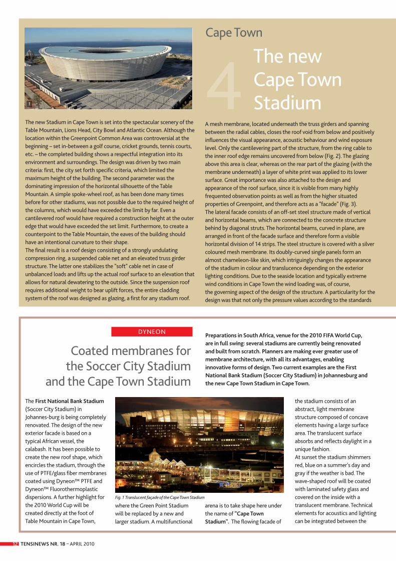
The new Stadium in Cape Town is set into the spectacular scenery of theTable Mountain, Lions Head, City Bowl and Atlantic Ocean. Although thelocation within the Greenpoint Common Area was controversial at thebeginning – set in-between a golf course, cricket grounds, tennis courts,etc. – the completed building shows a respectful integration into itsenvironment and surroundings. The design was driven by two maincriteria: first, the city set forth specific criteria, which limited themaximum height of the building. The second parameter was thedominating impression of the horizontal silhouette of the TableMountain. A simple spoke-wheel roof, as has been done many timesbefore for other stadiums, was not possible due to the required height ofthe columns, which would have exceeded the limit by far. Even acantilevered roof would have required a construction height at the outeredge that would have exceeded the set limit. Furthermore, to create acounterpoint to the Table Mountain, the eaves of the building shouldhave an intentional curvature to their shape.The final result is a roof design consisting of a strongly undulatingcompression ring, a suspended cable net and an elevated truss girderstructure. The latter one stabilizes the "soft" cable net in case ofunbalanced loads and lifts up the actual roof surface to an elevation thatallows for natural dewatering to the outside. Since the suspension roofrequires additional weight to bear uplift forces, the entire claddingsystem of the roof was designed as glazing, a first for any stadium roof.
A mesh membrane, located underneath the truss girders and spanningbetween the radial cables, closes the roof void from below and positivelyinfluences the visual appearance, acoustic behaviour and wind exposurelevel. Only the cantilevering part of the structure, from the ring cable tothe inner roof edge remains uncovered from below (Fig. 2). The glazingabove this area is clear, whereas on the rear part of the glazing (with themembrane underneath) a layer of white print was applied to its lowersurface. Great importance was also attached to the design andappearance of the roof surface, since it is visible from many highlyfrequented observation points as well as from the higher situatedproperties of Greenpoint, and therefore acts as a "facade" (Fig. 3).The lateral facade consists of an off-set steel structure made of verticaland horizontal beams, which are connected to the concrete structurebehind by diagonal struts. The horizontal beams, curved in plane, arearranged in front of the facade surface and therefore form a visiblehorizontal division of 14 strips. The steel structure is covered with a silvercoloured mesh membrane. Its doubly-curved single panels form analmost chameleon-like skin, which intriguingly changes the appearanceof the stadium in colour and translucence depending on the exteriorlighting conditions. Due to the seaside location and typically extremewind conditions in Cape Town the wind loading was, of course, the governing aspect of the design of the structure. A particularity for thedesign was that not only the pressure values according to the standards
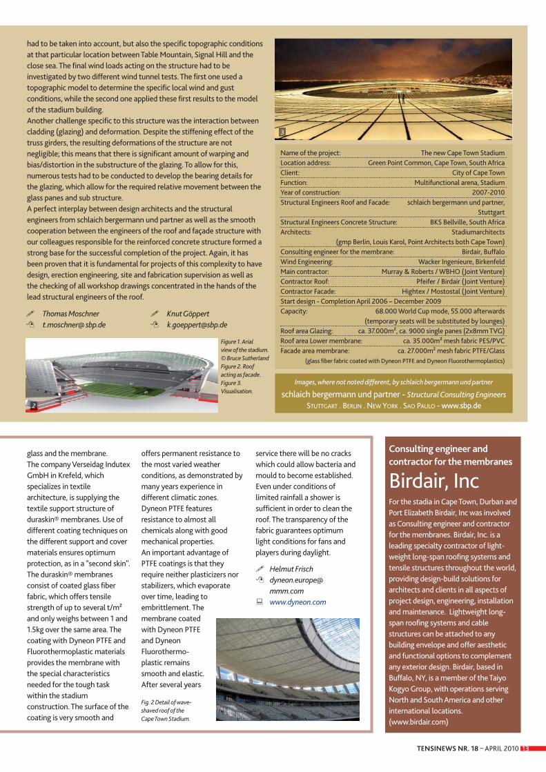
The First National Bank Stadium(Soccer City Stadium) in Johannes-burg is being completelyrenovated. The design of the newexterior facade is based on atypical African vessel, thecalabash. It has been possible tocreate the new roof shape, whichencircles the stadium, through theuse of PTFE/glass fiber membranescoated using Dyneon™ PTFE andDyneon™ Fluorothermo plasticdispersions. A further highlight forthe 2010 World Cup will becreated directly at the foot ofTable Mountain in Cape Town,
where the Green Point Stadiumwill be replaced by a new andlarger stadium. A multifunctional
arena is to take shape here underthe name of "Cape TownStadium". The flowing facade of
the stadium consists of anabstract, light membranestructure composed of concaveelements having a large surfacearea. The translucent surfaceabsorbs and reflects daylight in aunique fashion. At sunset the stadium shimmersred, blue on a summer's day andgray if the weather is bad. Thewave-shaped roof will be coatedwith laminated safety glass andcovered on the inside with atranslucent membrane. Technicalelements for acoustics and lightingcan be integrated between the
Cape Town
The new Cape Town Stadium
Coated membranes for the Soccer City Stadium
and the Cape Town Stadium
Preparations in South Africa, venue for the 2010 FIFA World Cup,are in full swing: several stadiums are currently being renovatedand built from scratch. Planners are making ever greater use ofmembrane architecture, with all its advantages, enablinginnovative forms of design. Two current examples are the FirstNational Bank Stadium (Soccer City Stadium) in Johannesburg andthe new Cape Town Stadium in Cape Town.
Fig. 1 Translucent façade of the Cape Town Stadium
1
DYNEON
TENSINEWS NR. 18 – APRIL 2010 13
glass and the membrane. The company Verseidag IndutexGmbH in Krefeld, whichspecializes in textilearchitecture, is supplying thetextile support structure ofduraskin® membranes. Use ofdifferent coating techniques onthe different support and covermaterials ensures optimumprotection, as in a "second skin".The duraskin® membranesconsist of coated glass fiberfabric, which offers tensilestrength of up to several t/m²and only weighs between 1 and1.5kg over the same area. Thecoating with Dyneon PTFE andFluorothermoplastic materialsprovides the membrane withthe special characteristicsneeded for the tough taskwithin the stadiumconstruction. The surface of thecoating is very smooth and
offers permanent resistance tothe most varied weatherconditions, as demonstrated bymany years experience indifferent climatic zones.Dyneon PTFE featuresresistance to almost allchemicals along with goodmechanical properties. An important advantage ofPTFE coatings is that theyrequire neither plasticizers norstabilizers, which evaporateover time, leading toembrittlement. Themembrane coatedwith Dyneon PTFEand DyneonFluorothermo-plastic remainssmooth and elastic.After several years
service there will be no crackswhich could allow bacteria andmould to become established. Even under conditions oflimited rainfall a shower issufficient in order to clean theroof. The transparency of thefabric guarantees optimumlight conditions for fans andplayers during daylight.
� Helmut Frisch� dyneon.europe@
mmm.com� www.dyneon.com
had to be taken into account, but also the specific topographic conditionsat that particular location between Table Mountain, Signal Hill and theclose sea. The final wind loads acting on the structure had to beinvestigated by two different wind tunnel tests. The first one used atopographic model to determine the specific local wind and gustconditions, while the second one applied these first results to the modelof the stadium building.Another challenge specific to this structure was the interaction betweencladding (glazing) and deformation. Despite the stiffening effect of thetruss girders, the resulting deformations of the structure are notnegligible; this means that there is significant amount of warping andbias/distortion in the substructure of the glazing. To allow for this,numerous tests had to be conducted to develop the bearing details forthe glazing, which allow for the required relative movement between theglass panes and sub structure.A perfect interplay between design architects and the structuralengineers from schlaich bergermann und partner as well as the smoothcooperation between the engineers of the roof and façade structure withour colleagues responsible for the reinforced concrete structure formed astrong base for the successful completion of the project. Again, it hasbeen proven that it is fundamental for projects of this complexity to havedesign, erection engineering, site and fabrication supervision as well asthe checking of all workshop drawings concentrated in the hands of thelead structural engineers of the roof.
Name of the project: The new Cape Town StadiumLocation address: Green Point Common, Cape Town, South AfricaClient: City of Cape TownFunction: Multifunctional arena, StadiumYear of construction: 2007-2010Structural Engineers Roof and Facade: schlaich bergermann und partner,
StuttgartStructural Engineers Concrete Structure: BKS Bellville, South AfricaArchitects: Stadiumarchitects
(gmp Berlin, Louis Karol, Point Architects both Cape Town)Consulting engineer for the membrane: Birdair, BuffaloWind Engineering: Wacker Ingenieure, BirkenfeldMain contractor: Murray & Roberts / WBHO (Joint Venture)Contractor Roof: Pfeifer / Birdair (Joint Venture)Contractor Facade: Hightex / Mostostal (Joint Venture)Start design - Completion April 2006 – December 2009Capacity: 68.000 World Cup mode, 55.000 afterwards
(temporary seats will be substituted by lounges)Roof area Glazing: ca. 37.000m², ca. 9000 single panes (2x8mm TVG)Roof area Lower membrane: ca. 35.000m² mesh fabric PES/PVCFacade area membrane: ca. 27.000m² mesh fabric PTFE/Glass
(glass fiber fabric coated with Dyneon PTFE and Dyneon Fluorothermoplastics)
Fig. 2 Detail of wave-shaved roof of the Cape Town Stadium.
Consulting engineer andcontractor for the membranes
Birdair, Inc For the stadia in Cape Town, Durban andPort Elizabeth Birdair, Inc was involvedas Consulting engineer and contractorfor the membranes. Birdair, Inc. is aleading specialty contractor of light -weight long-span roofing systems andtensile structures throughout the world,providing design-build solutions forarchitects and clients in all aspects ofproject design, engineering, installationand maintenance. Lightweight long-span roofing systems and cablestruc tures can be attached to anybuilding envelope and offer aestheticand functional options to complementany exterior design. Birdair, based inBuffalo, NY, is a member of the TaiyoKogyo Group, with operations servingNorth and South America and otherinter national locations.(www.birdair.com)
Images, where not noted different, by schlaich bergermann und partner
schlaich bergermann und partner - Structural Consulting Engineers STUTTGART . BERLIN . NEW YORK . SAO PAULO - www.sbp.de2
� Thomas Moschner� t.moschner@ sbp.de
� Knut Göppert� [email protected]
3
Figure 1. Arial view of the stadium. © Bruce SutherlandFigure 2. Roofacting as facade.Figure 3. Visualisation.
TENSINEWS NR. 18 – APRIL 201014
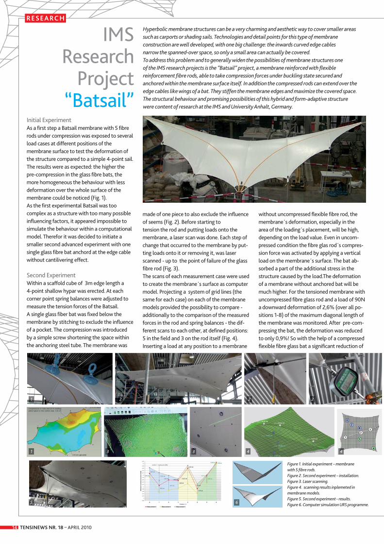
Initial ExperimentAs a first step a Batsail membrane with 5 fibrerods under compression was exposed to severalload cases at different positions of the membrane surface to test the deformation ofthe structure compared to a simple 4-point sail.The results were as expected: the higher thepre-compression in the glass fibre bats, themore homogeneous the behaviour with lessdeformation over the whole surface of themembrane could be noticed (Fig. 1).As the first experimental Batsail was too complex as a structure with too many possibleinfluencing factors, it appeared impossible tosimulate the behaviour within a computationalmodel. Therefor it was decided to initiate asmaller second advanced experiment with onesingle glass fibre bat anchord at the edge cablewithout cantilivering effect.
Second ExperimentWithin a scaffold cube of 3m edge length a 4-point shallow hypar was erected. At eachcorner point spring balances were adjusted tomeasure the tension forces of the Batsail. A single glass fiber bat was fixed below themembrane by stitching to exclude the influenceof a pocket. The compression was introducedby a simple screw shortening the space withinthe anchoring steel tube. The membrane was
made of one piece to also exclude the influenceof seems (Fig. 2). Before starting to tension the rod and putting loads onto themembrane, a laser scan was done. Each step ofchange that occurred to the membrane by put-ting loads onto it or removing it, was laserscanned - up to the point of failure of the glassfibre rod (Fig. 3). The scans of each measurement case were usedto create the membrane´s surface as computermodel. Projecting a system of grid lines (thesame for each case) on each of the membranemodels provided the possibility to compare -additionally to the comparison of the measuredforces in the rod and spring balances - the dif-ferent scans to each other, at defined positions:5 in the field and 3 on the rod itself (Fig. 4). Inserting a load at any position to a membrane
without uncompressed flexible fibre rod, themembrane´s deformation, especially in thearea of the loading´s placement, will be high,depending on the load value. Even in uncom-pressed condition the fibre glas rod´s compres-sion force was activated by applying a verticalload on the membrane´s surface. The bat ab-sorbed a part of the additional stress in thestructure caused by the load.The deformationof a membrane without anchored bat will bemuch higher. For the tensioned membrane withuncom pressed fibre glass rod and a load of 90Na downward deformation of 2,6% (over all po-sitions 1-8) of the maximum diagonal length ofthe membrane was monitored. After pre-com-pressing the bat, the deformation was reducedto only 0,9%! So with the help of a compressedflexible fibre glass bat a significant reduction of
Hyperbolic membrane structures can be a very charming and aesthetic way to cover smaller areassuch as carports or shading sails. Technologies and detail points for this type of membraneconstruction are well developed, with one big challenge: the inwards curved edge cables narrow the spanned-over space, so only a small area can actually be covered.To address this problem and to generally widen the possibilities of membrane structures one of the IMS research projects is the ”Batsail” project, a membrane reinforced with flexiblereinforcement fibre rods, able to take compression forces under buckling state secured and anchored within the membrane surface itself. In addition the compressed rods can extend over theedge cables like wings of a bat. They stiffen the membrane edges and maximize the covered space.The structural behaviour and promising possibilities of this hybrid and form-adaptive structure were content of research at the IMS and University Anhalt, Germany.
IMS Research
Project “Batsail”
RESEARCH
Figure 1. Initial experiment – membrane with 5 fibre rods.Figure 2. Second experiment – installation.Figure 3. Laser scanning. Figure 4. scanning results inplemeted inmembrane models.Figure 5. Second experiment - results. Figure 6. Computer simulation URS programme.
1 2 2 2
1
5 6
3 3 4 4
TENSINEWS NR. 18 – APRIL 2010 15
ARTICLE
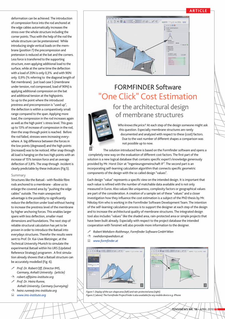
FORMFINDER Software"One Click" Cost Estimation
for the architectural design of membrane structures
Who knows the price? At each step of the design someone might askthis question. Especially membrane structures are rarelydocumented and analyzed with respect to these (cost) factors.Due to the vast number of different shapes a comparison wasnot possible up to now.
The solution introduced here is based on the Formfinder software and opens acompletely new way on the evaluation of different cost factors. The first part of the
solution is a new logical database that contains specific expert’s knowledge generouslyprovided by Mr. Horst Dürr at “Ingenieursgemeinschaft IF”. The second part is anincorporating self-learning calculation algorithm that connects specific geometriccomponents of the design with the so called design "values".
Each design "value" represents a specific view on the intended design. It is important thateach value is refined with the number of matchable data available and is not onlymeasured in Euros. Also values like uniqueness, complexity factors or geographical valuesare part of the consideration. A creation of a sample set of these "values" and a closerinvestigation how they influence the cost estimation is a subject of the PhD thesis by Mr.Nikolay Kim who is working in the Formfinder Software Development Team. The intentionof the self-learning calculation process is to support the designer at each step of the designand to increase the architectural quality of membrane structures. The integrated designtool also includes "values" like the shaded area, rain-protected area or simple projects thathave been built already. Especially with respect to the project database the intendedcooperation with Tensinet will also provide more information to the designer.
� Robert Wehdorn-Roithmayr, Formfinder Software GmbH Wien� [email protected]� www.formfinder.at
deformation can be achieved. The introductionof compression force into the rod anchored atthe edge cables automatically increases thestress over the whole structure including the corner points. Thus with the help of the rod thewhole structure can be pretensioned. While introducing single vertical loads on the mem-brane (position 7) the precompression and pretension is reduced at the bat and the corners.Less force is transferred to the supporting structure, even applying additional load to thesurface, while at the same time the deflectionwith a load of 20N is only 0,3% and with 90Nonly 0,9% (% referring to the diagonal length offlat membrane). Just load case 5 (membraneunder tension, rod compressed, load of 90N) is applying additional compression on the bat and additional tension at the highpoints. So up to the point where the introduced prestress and precompression is “used up”, the deflection is within a comparetively smallrange compared to the span. Applying moreload, the compression in the rod increases againas well as the high point´s stress level. This goesup to 13% of increase of compression in the rod,then the snap through point is reached. Beforethe rod failed, stresses were increasing every-where. A big difference between the forces inthe low points (degreased) and the high points(increased) was to be noticed. After snap throughall load is hanging on the two high points with anincrease of 15% tension force and an average deflection of 3,8%. The snap through incident isclearly predictable by these indicators (Fig.5).
SummaryStructures like the Batsail - with flexible fibrerods anchored to a membrane - allow us to enlarge the covered area by “pushing the edgecables” outside. The main unexpected advantage is the possiblity to significantly reduce the deflection under load without havingto increase the prestress level of the membraneby higher anchoring forces. This enables largerspans with less deflection, smaller mast dimensions and foundations. The next step ofreliable structural calculation has yet to beproven in order to introduce the Batsail intoeverydays structures. Therefor the results weresent to Prof. Dr. Kai-Uwe Bletzinger, at the Technical University Munich to simulate the experimental Batsail within his URS (UpdatedReference Strategy) programm . A first simula-tion already showes that a Batsail structure canbe accurately modelled (Fig. 6).
� Prof. Dr. Robert Off, Director IMS, Germany, Anhalt University. (article)
� [email protected]� Prof. Dr. Heinz Runne,
Anhalt University, Germany (surveying)� heinz.runne@ ims-institute.org� www.ims-institute.org
Figure 1. Display of the sun-shape area (left) and rain-protected area (right).Figure 2 ( above) The Formfinder ProjectFinder is also available for any mobile device e.g. iPhone
2
1 1
TENSINEWS NR. 18 – APRIL 201016
ARQUITEXTIL FHECOR
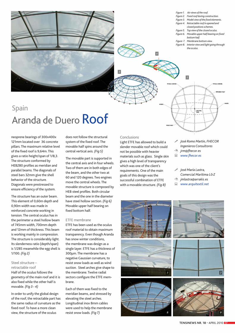
Architectural conceptAranda de Duero is a town inCastille (Spain). A new Arenawas constructed in this town. The building consists of acircular grandstand and a globalroof. The roof is partiallyretractable in order to adapt theconfiguration of the building todifferent events. The Arena has acircular shape in plan with adiameter of 80,14m. The roof
was designed as a shellstructure. Half of the centralpart of the roof is retractableand has a shape of sphericalsector of 32,90m of diameter inplan. (Fig 1)
Steel structure – fixed roofThe main structure has aSchwelder configuration. A spherical shape supportedonly in the perimeter by
ETFE single skin
Name of the project: ETFE SINGLE SKIN ARANDA DE DUERO ROOFLocation: Aranda de Duero, SpainClient: Victoriano del RíoFunction of the building: Concerts, sports and bullfighting ArenaType of application of the membrane: Protection against environmental
hazards and light transmissionYear of construction: 2006Architectural Design: José Romo (FHECOR Ingenieros Consultores)
José María Lastra (Comercial Marítima L&Z)Structural Engineers: José Romo (FHECOR Ingenieros Consultores) Consulting engineer for the membrane: José Romo (FHECOR Ingenieros
Consultores) & José María Lastra (Comercial Marítima L&Z)Tensile membrane contractor: Comercial Marítima L&ZSupplier: Nowofol GmbH Manufacture and installation: Comercial Marítima L&Z Material: Nowoflon ET 6235 300 μm ETFE Cover surface: 1.400m²
1 1
Lone Butte Casino Lights Up the Desert SkyChandler, Arizona, USA
USA-SHADE
Location address: Chandler, Arizona, USAClient: Gila River Indian CommunityFunction of building: main entrance CasinoType of application of the membrane: canopy Year of Construction: 2009Architects: Paul Hamel (Group West Architects)Engineering: FabriTec StructuresContractor: JE Dunn ConstructionSupplier of the membrane material: Saint-Gobain & MultiKnitManufacture and Installation: FabriTec Structures
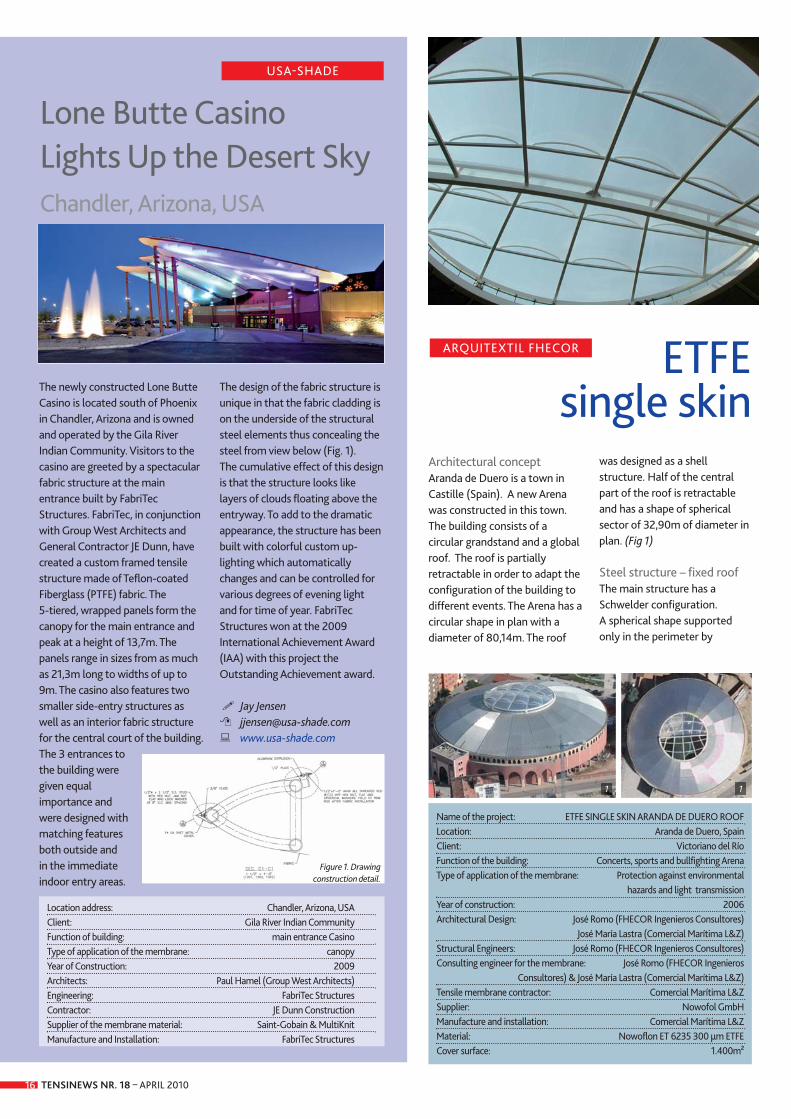
The newly constructed Lone ButteCasino is located south of Phoenixin Chandler, Arizona and is ownedand operated by the Gila RiverIndian Community. Visitors to thecasino are greeted by a spectacularfabric structure at the mainentrance built by FabriTecStructures. FabriTec, in conjunctionwith Group West Architects andGeneral Contractor JE Dunn, havecreated a custom framed tensilestructure made of Teflon-coatedFiberglass (PTFE) fabric. The 5-tiered, wrapped panels form thecanopy for the main entrance andpeak at a height of 13,7m. Thepanels range in sizes from as muchas 21,3m long to widths of up to9m. The casino also features twosmaller side-entry structures aswell as an interior fabric structurefor the central court of the building.The 3 entrances tothe building weregiven equalimportance andwere designed withmatching featuresboth outside and in the immediateindoor entry areas.
The design of the fabric structure isunique in that the fabric cladding ison the underside of the structuralsteel elements thus concealing thesteel from view below (Fig. 1). The cumulative effect of this designis that the structure looks likelayers of clouds floating above theentryway. To add to the dramaticappearance, the structure has beenbuilt with colorful custom up-lighting which automaticallychanges and can be controlled forvarious degrees of evening lightand for time of year. FabriTecStructures won at the 2009International Achievement Award(IAA) with this project theOutstanding Achievement award.
� Jay Jensen� [email protected]� www.usa-shade.com
Figure 1. Drawing construction detail.
neoprene bearings of 300x400x121mm located over 36 concretepillars. The maximum relative levelof the fixed roof is 9,64m. Thisgives a ratio height/span of 1/8,3. The structure conformed byHEB280 profiles as meridian andparallel beams. The diagonals ofsteel bars 32mm give the shellbehavior of the structure.Diagonals were prestressed toensure efficiency of the system.
The structure has an outer beam.This element of 0,60m depth and0,90m width was made inreinforced concrete working intension. The central oculus has inthe perimeter a steel hollow beamof 745mm width, 700mm depthand 12mm of thickness. This beamis working mainly in compression.The structure is considerably light.Its slenderness ratio (depth/span)is 1/285 meanwhile the egg shell is1/100. (Fig 2)
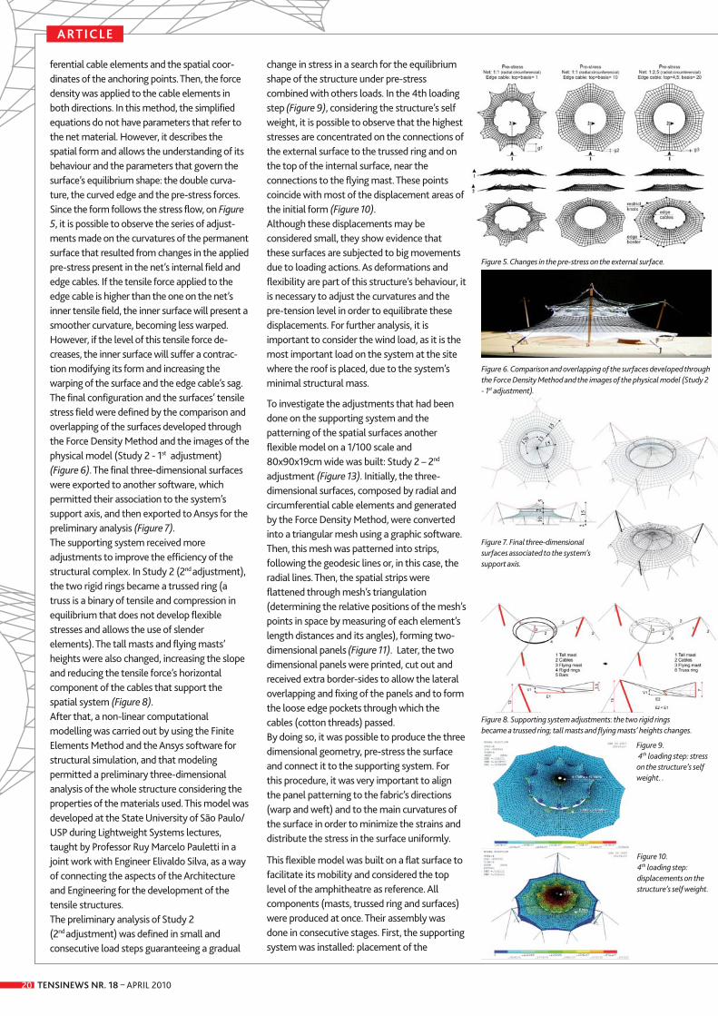
Steel structure – retractable roofHalf of the oculus follows thegeometry of the main roof and it isalso fixed while the other half ismovable. (Fig 3 - 4)
In order to unify the global designof the roof, the retractable part hasthe same radius of curvature as thefixed roof. To have a more cleanview, the structure of the oculus
does not follow the structuralsystem of the fixed roof. Themovable half spins around thecentral vertical axis. (Fig 5)
The movable part is supported inthe central axis and in four wheels.Two of them are in both edges ofthe beam, and the other two at 60 and 120 degrees. Two enginesmove the central wheels. Themovable structure is composed byHEB steel profiles. Both circularbeam and the one in the diameterhave steel hollow section. (Fig 6) Movable upper half bearing onfixed bottom half.
ETFE membraneETFE has been used as the oculusroof material to obtain maximumtransparency. Even though Arandahas snow winter conditions, the membrane was design as asingle layer. ETFE has a thickness of300μm. The membrane has anegative Gaussian curvature, toresist snow loads as well as windsuction. Steel arches give shape tothe membrane. Twelve radialsectors configure the ETFE mem -brane.
Each of them was fixed to themeridian beams, and stressed byelevating the steel arches.Longitudinal inox 8mm cableswere used to help the membraneresist snow loads. (Fig 7)
ConclusionsLight ETFE has allowed to build aslender movable roof which couldnot be possible with heaviermaterials such as glass. Single skingives a high level of tran sparencywhich was one of the client’srequirements. One of the maingoals of this design was thesuccessful combination of ETFEwith a movable structure. (Fig 8)
� José Romo Martin, FHECOR Ingenieros Consultores
� [email protected]� www.fhecor.es
� José María Lastra,Comercial Marítima L&Z
� [email protected]� www.arquitextil.net
TENSINEWS NR. 18 – APRIL 2010 17
Figure 1. Air views of the roof.Figure 2. Fixed roof during construction.Figure 3. Model view of the fixed elements.Figure 4. Retractable roof in opened and
closed positions schemes.Figure 5. Top view of the closed oculus.Figure 6. Movable upper half bearing on fixed
bottom half.Figure 7. Membrane bottom view.Figure 8. Interior view and light going through
the oculus.
Spain
Aranda de Duero Roof
2
3
4
5
6
77
88

TENSINEWS NR. 18 – APRIL 2010
ARTICLE
18
1. IntroductionTensile surface structures are three-dimensionalsystems composed by the association ofmembranes and a supporting system (cables,masts, arches, trusses, etc. normally in steel)under a tensile state. Having minimal weightwhen comparing with the supported load, thesestructures are very flexible, a result of thesubstitution of the material mass by theappropriate form to achieve stability. Theyintroduce a unique structural approach, in whichthe form derives from the flow of forces in thestructure. Thus, the stability, performance andefficiency of the system are dependent on thegeometry, the pre-stress state and thecontinuous and integrated work of all thestructural components.
This approach represents a major challenge toarchitects and engineers: the structural solutionneeds an accurate design, the knowledge on thesystem’s conditions and parameters and,besides that, it must incorporate the structuralanalysis to the conception of the project.Therefore, the design process in this case isdifferent from the traditional one, as it shouldconcentrate the efforts of a multidisciplinaryteam (architects, engineers, manufacturers etc),becoming the result of this team’s interactionsince the beginning. Consequently, the qualityof the spatial and structural solution and theproduction of accurate information for thepartially industrialized building process are aresult of the dialogue among the members ofthe team and the integration of their workactions.
2. Method of workIn this case study, the particular method of workused comprises the conception of the project aswell as the design process. The conception aimsto set up the project’s guidelines or, in otherwords, to understand and define the use,activities and the identity of the object that willbe built, such as the building site’s qualities andits characteristics (views, topography, influenceof the wind/sun, neighbourhood, relation withthe landscape and city, and the local laws). Thedesign process includes physical andcomputational modelling and permits thedevelopment of the system’s equilibriumconfiguration, gradually exploring the benefitsof having Architecture and Engineering workingtogether.
The physical modelling can be accuratelycarried out on and allows the investigation ofthe geometry and the behaviour of thecomponents under a tensile stress field.However, the method of using flexible physicalmodels was indirect in this case study. Thatmeans it was based on the identification andmapping of the most important characteristicsof the constructive system (geometry andintegrated work of the components under atensile state) for later observations andqualitative analysis of the system’s behaviour.The dimensions and parameters involved on thephysical model and the ones of the realstructure are the same but, there is nogeometric factor to establish a relation betweenthe material’s properties (unit weight and load),a fact that could turn evaluation into a
simplified representation of the reality. The computational models comprise theengineering of the structure, including theselection of the materials and the analysis anddesign of the system. The Density Force Methodand the Finite Elements Method were usedwhen studying this roof. They made possible themodelling of the initial surfaces (form finding)and the preliminary non-linear analysis of all thestructure, refining the research on theequilibrium configuration of the proposedmodel.
2.1 Conception of the design or guidelines of the projectThe site chosen to reveal the proposed coveringmodel is the amphitheatre square of the FederalUniversity of Ouro Preto, which is a largestrategic area, situated in the centre of the maincampus (Figure 1). Within this academiccontext, the proposed project intends to givevisibility and a purpose to the place, stimulatingthe local use under different weather conditions– a cultural, academic or ephemeral use. The proposed configuration occupies an area of 2212m² and is composed by two surfaces: a permanent one (external) and a retractableone (internal). This creates an appropriatesolution: it protects from rain or sun, it providesthe experience of open and close spaces, itpermits occasional changes and offers flexibilitytowards the most different uses. It also exploresthe possibilities for natural lighting andventilation of the large free space as well as theopenings to the nice views and relation with thelandscape. A frequent use will improve thesafety of the place.
2.2 Designing process The first stage of the design process comprisedthe insertion of the structural project on thelocal physical context using physical models.The initial models, with scale of 1:500 (Figures 2,3), explores different structural configurationsand allows the intuitive understanding of theglobal system. The models on scales 1:200(Figure 4) and 1:100 (Figures 12, 13) provide amore detailed comprehension. The 1:500 and1:200 models were built with nails, fishhooks,cotton thread, nylon fabric from woman’sstocking and cardboard for their bases. For the1:100 model, paper, cotton, steel thread andhardboard for the base were employed.
The first proposed configuration - Study 1(a 17x18x5cm flexible model built on a 1:500scale) presents the system’s support and the
Case study ‘Tensile surfaces The present case study – a membrane roof model – took form during a Mastering Research at theUniversity of Ouro Preto, Brazil and aims to explore the characteristics of the roof constructionsystem when applied to a particular situation and to analyze the joint work of Engineering andArchitecture on the development of tensile surface structures. It was studied through a particularmethod of work – which involves flexible, physical and computational models and from which thequalitative and structural solutions are derived. In 2007, the model built for this study was awardedthe First Prize at Valmex Structure 2007's competition, organized by Mehler Texnologies in Brazil.
Figure 1. Amphitheatre square of the Federal University of Ouro Preto

TENSINEWS NR. 18 – APRIL 2010 19
ARTICLE
permanent external roof. A three-dimensionalsystem supports the top of this roof. It issupported by four tall rigid masts and rigid barelements, with no continuity, inserted in acontinuous net of tensile cables and defining astable and articulated spatial system(Tensegrity’s Principle). The system is associatedto two rigid rings: the inner ring, connected tocables, and the outer ring, connected to the rigidbars. This association brings more stability andstiffness to the system.
On the second proposal - Study 2(a 17x18x5cm flexible model built on a 1/500scale) the top of the roof is also supported bythe three-dimensional system and the basis isstill sustained by the same tall masts (Figure 3).The main difference is that the basis is now at ahigher position in reference to the ground dueto shorter masts added to the model. Anotherdifference resides in the fact that the spatialsystem is supported by three tall independentmasts that are no longer rigid but present ahinge and tensile cables. The three-dimensionalpin-ended mast’s configuration is a stable shapein space that avoids the flexural moment. Thecompressed mast and the two tensile cablesalso enable the reduction of the structure’sweight, increasing its efficiency.The Study 2 was chosen to give continuity tothe research on the geometry and behavior ofthe roof due to the simplicity and thechallenging balance situation of the supportingsystem in addition to the search for theintegration of the proposed tensile membranestructure with the landscape.
Hence, a new flexible model was created (scale1/200, 50x50x10cm) in order to study thecomplete roof. This Study 2 (1st adjustment)revealed the necessity of some modifications onthe supporting system (Figure 4). Thus, thespatial system received a central flying mastand the rigid bar elements were connected totwo rigid rings. The central flying mast’s role isto support the high points of the convertiblesurface and by doing so it becomes the centralelement of the spatial supporting system. Thetwo rigid rings have different diameters and areset on different planes in order to permit theoverlapping and the support of the roofs. Thecomplete roof also has different arrangementand behaviour, being now composed by twoanticlastic surfaces (double curvature inopposite directions). The external permanentsurface is a cone shape, with its top supportedby the internal ring and its basis by the small
and tall masts. The internal convertible roofpresents a radial array of nine modules ofsaddle-shaped form. The top of the flying mastsupports the roof’s centre and cables anchoredto nine points of both external rings supportingthe roof’s basis. When closed, the centrallybunched surface is protected by a glass roof. Themechanisms responsible for the movement ofthe internal roof are activated by sliding engines(tractors) that connect the membrane’s edgesto the cables. These tractors, driven bysynchronized electric engines, move freely alongthe cables (which are supported by the topfloating mast and the rings) opening andtensioning or closing the membrane roof.However, to make the opening and tensioningof this surface possible, the flying mast mayhave a retractile mechanism that allows theheight adjustment of the system.
The second stage of this process included theregistration and the computational modelling ofthe developed proposed system: Study 2 (1st adjustment). It involves the initial surfaces’modelling (form finding) and the system’spreliminary analysis. Initially, the surfaces were modelled throughthe Force Density Method using Densalfa,software developed by Vinícius de Oliveira(OLIVEIRA, 2003). The force density is an initialtensile force based in a constant relationbetween force and the length of each barelement, allowing an internal equilibrium of pre-stress forces. In this mathematicalapproximation, the equilibrium form of thesurface relates the geometry and an internaltensile stress field. Thus, the membrane surfacewas discretised as a cable net by the definition ofa net mesh composed by radial and circum -
structures’ design process
Figure 4. Views flexible model: Study 2 (1st adjustment), scale 1/200; Mechanisms responsible for the movement of the internal roof 1. Permanent covering - 2. Convertible covering; Support system: 3. tall masts - 4. small masts - 5. cables - 6.rigid rings - 7. rigid bars - 8. flying mast -8. cables that support sliding tractors - 9. tractor.
Figure 3. View: three-dimensional of flexible model – Study 2,scale 1/500 Permanent covering: Support system: 2. cables-
3. rigid rings - 4. bars - 5. tall masts - 6. small masts
Figure 2. View: three-dimensional of flexible model – Study 1,scale 1/500 Permanent covering: Support system: 2. cables-
3. rigid rings - 4. bars - 5. tall masts
TENSINEWS NR. 18 – APRIL 201020
ARTICLE
ferential cable elements and the spatial coor -dinates of the anchoring points. Then, the forcedensity was applied to the cable elements inboth directions. In this method, the simplifiedequations do not have parameters that refer tothe net material. However, it describes thespatial form and allows the understanding of itsbehaviour and the parameters that govern thesurface’s equilibrium shape: the double cur va -ture, the curved edge and the pre-stress forces. Since the form follows the stress flow, on Figure5, it is possible to observe the series of adjust-ments made on the curvatures of the permanentsurface that resulted from changes in the appliedpre-stress present in the net’s internal field andedge cables. If the tensile force applied to theedge cable is higher than the one on the net’sinner tensile field, the inner surface will present asmoother curvature, becoming less warped.However, if the level of this tensile force de-creases, the inner surface will suffer a contrac-tion modifying its form and increasing thewarping of the surface and the edge cable’s sag. The final configuration and the surfaces’ tensilestress field were defined by the comparison andoverlapping of the surfaces developed throughthe Force Density Method and the images of thephysical model (Study 2 - 1st adjustment)(Figure 6). The final three-dimensional surfaceswere exported to another software, whichpermitted their association to the system’ssupport axis, and then exported to Ansys for thepreliminary analysis (Figure 7). The supporting system received moreadjustments to improve the efficiency of thestructural complex. In Study 2 (2nd adjustment),the two rigid rings became a trussed ring (atruss is a binary of tensile and compression inequilibrium that does not develop flexiblestresses and allows the use of slenderelements). The tall masts and flying masts’heights were also changed, increasing the slopeand reducing the tensile force’s horizontalcomponent of the cables that support thespatial system (Figure 8). After that, a non-linear computationalmodelling was carried out by using the FiniteElements Method and the Ansys software forstructural simulation, and that modelingpermitted a preliminary three-dimensionalanalysis of the whole structure considering theproperties of the materials used. This model wasdeveloped at the State University of São Paulo/USP during Lightweight Systems lectures,taught by Professor Ruy Marcelo Pauletti in ajoint work with Engineer Elivaldo Silva, as a wayof connecting the aspects of the Architectureand Engineering for the development of thetensile structures. The preliminary analysis of Study 2 (2nd adjustment) was defined in small andconsecutive load steps guaranteeing a gradual
change in stress in a search for the equilibriumshape of the structure under pre-stresscombined with others loads. In the 4th loadingstep (Figure 9), considering the structure’s selfweight, it is possible to observe that the higheststresses are concentrated on the connections ofthe external surface to the trussed ring and onthe top of the internal surface, near theconnections to the flying mast. These pointscoincide with most of the displacement areas ofthe initial form (Figure 10). Although these displacements may beconsidered small, they show evidence thatthese surfaces are subjected to big movementsdue to loading actions. As deformations andflexibility are part of this structure’s behaviour, itis necessary to adjust the curvatures and thepre-tension level in order to equilibrate thesedisplacements. For further analysis, it isimportant to consider the wind load, as it is themost important load on the system at the sitewhere the roof is placed, due to the system’sminimal structural mass.
To investigate the adjustments that had beendone on the supporting system and thepatterning of the spatial surfaces anotherflexible model on a 1/100 scale and80x90x19cm wide was built: Study 2 – 2nd
adjustment (Figure 13). Initially, the three-dimensional surfaces, composed by radial andcircumferential cable elements and generatedby the Force Density Method, were convertedinto a triangular mesh using a graphic software.Then, this mesh was patterned into strips,following the geodesic lines or, in this case, theradial lines. Then, the spatial strips wereflattened through mesh’s triangulation(determining the relative positions of the mesh’spoints in space by measuring of each element’slength distances and its angles), forming two-dimensional panels (Figure 11). Later, the twodimensional panels were printed, cut out andreceived extra border-sides to allow the lateraloverlapping and fixing of the panels and to formthe loose edge pockets through which thecables (cotton threads) passed. By doing so, it was possible to produce the threedimensional geometry, pre-stress the surfaceand connect it to the supporting system. Forthis procedure, it was very important to alignthe panel patterning to the fabric’s directions(warp and weft) and to the main curvatures ofthe surface in order to minimize the strains anddistribute the stress in the surface uniformly.
This flexible model was built on a flat surface tofacilitate its mobility and considered the toplevel of the amphitheatre as reference. Allcomponents (masts, trussed ring and surfaces)were produced at once. Their assembly wasdone in consecutive stages. First, the supportingsystem was installed: placement of the
Figure 5. Changes in the pre-stress on the external surface.
Figure 6. Comparison and overlapping of the surfaces developed throughthe Force Density Method and the images of the physical model (Study 2- 1st adjustment).
Figure 7. Final three-dimensionalsurfaces associated to the system’ssupport axis.
Figure 8. Supporting system adjustments: the two rigid ringsbecame a trussed ring; tall masts and flying masts’ heights changes.
Figure 9.4th loading step: stresson the structure’s selfweight. .
Figure 10. 4th loading step:displacements on thestructure’s self weight.
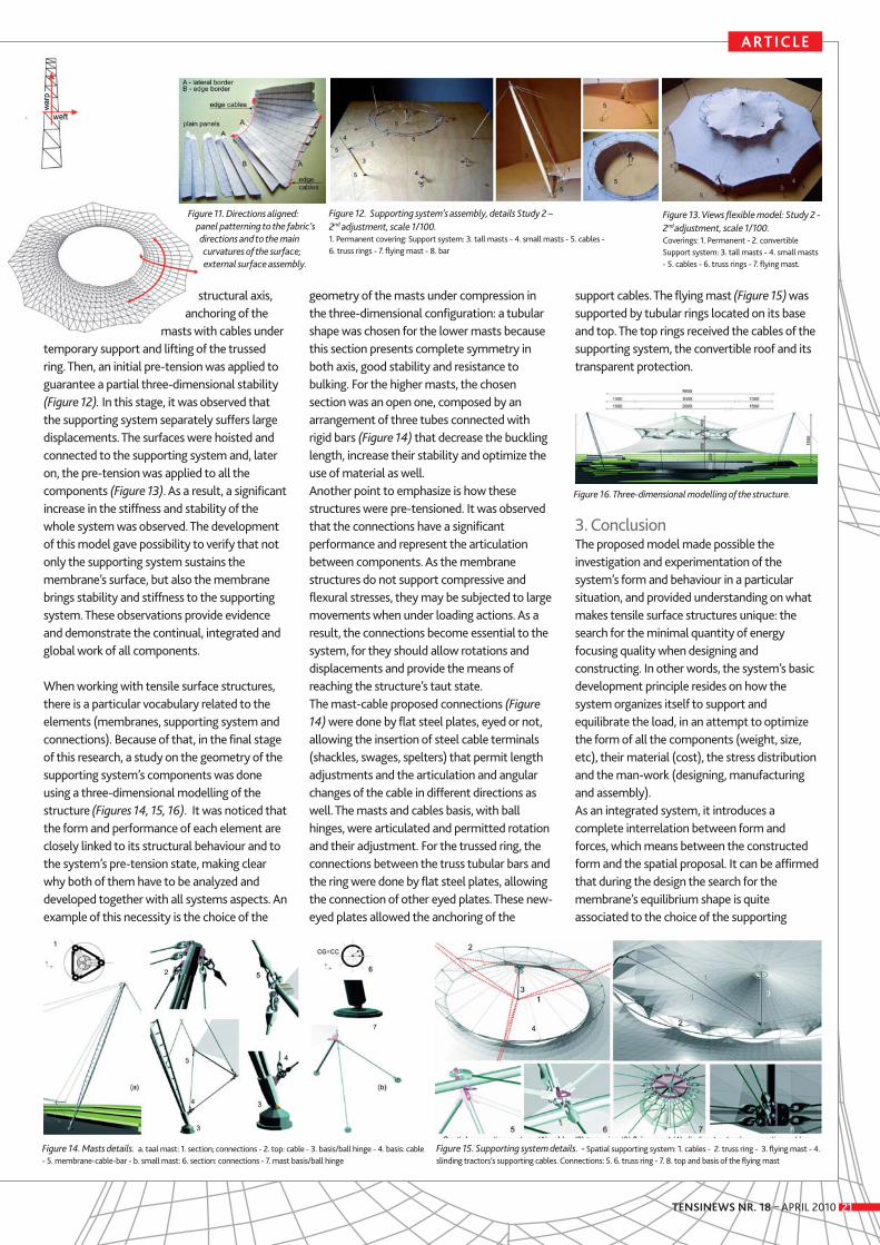
TENSINEWS NR. 18 – APRIL 2010 21
ARTICLE
Figure 11. Directions aligned: panel patterning to the fabric’sdirections and to the maincurvatures of the surface;external surface assembly.
Figure 12. Supporting system’s assembly, details Study 2 – 2nd adjustment, scale 1/100. 1. Permanent covering: Support system: 3. tall masts - 4. small masts - 5. cables - 6. truss rings - 7. flying mast - 8. bar
Figure 13. Views flexible model: Study 2 -2nd adjustment, scale 1/100. Coverings: 1. Permanent - 2. convertibleSupport system: 3. tall masts - 4. small masts- 5. cables - 6. truss rings - 7. flying mast.
structural axis,anchoring of the
masts with cables undertemporary support and lifting of the trussedring. Then, an initial pre-tension was applied toguarantee a partial three-dimensional stability(Figure 12). In this stage, it was observed thatthe supporting system separately suffers largedisplacements. The surfaces were hoisted andconnected to the supporting system and, lateron, the pre-tension was applied to all thecomponents (Figure 13). As a result, a significantincrease in the stiffness and stability of thewhole system was observed. The developmentof this model gave possibility to verify that notonly the supporting system sustains themembrane’s surface, but also the membranebrings stability and stiffness to the supportingsystem. These observations provide evidenceand demonstrate the continual, integrated andglobal work of all components.
When working with tensile surface structures,there is a particular vocabulary related to theelements (membranes, supporting system andconnections). Because of that, in the final stageof this research, a study on the geometry of thesupporting system’s components was doneusing a three-dimensional modelling of thestructure (Figures 14, 15, 16). It was noticed thatthe form and performance of each element areclosely linked to its structural behaviour and tothe system’s pre-tension state, making clearwhy both of them have to be analyzed anddeveloped together with all systems aspects. Anexample of this necessity is the choice of the
geometry of the masts under compression inthe three-dimensional configuration: a tubularshape was chosen for the lower masts becausethis section presents complete symmetry inboth axis, good stability and resistance tobulking. For the higher masts, the chosensection was an open one, composed by anarrangement of three tubes connected withrigid bars (Figure 14) that decrease the bucklinglength, increase their stability and optimize theuse of material as well. Another point to emphasize is how thesestructures were pre-tensioned. It was observedthat the connections have a significantperformance and represent the articulationbetween components. As the membranestructures do not support compressive andflexural stresses, they may be subjected to largemovements when under loading actions. As aresult, the connections become essential to thesystem, for they should allow rotations anddisplacements and provide the means ofreaching the structure’s taut state.The mast-cable proposed connections (Figure14) were done by flat steel plates, eyed or not,allowing the insertion of steel cable terminals(shackles, swages, spelters) that permit lengthadjustments and the articulation and angularchanges of the cable in different directions aswell. The masts and cables basis, with ballhinges, were articulated and permitted rotationand their adjustment. For the trussed ring, theconnections between the truss tubular bars andthe ring were done by flat steel plates, allowingthe connection of other eyed plates. These new-eyed plates allowed the anchoring of the
support cables. The flying mast (Figure 15) wassupported by tubular rings located on its baseand top. The top rings received the cables of thesupporting system, the convertible roof and itstransparent protection.
3. ConclusionThe proposed model made possible theinvestigation and experimentation of thesystem’s form and behaviour in a particularsituation, and provided understanding on whatmakes tensile surface structures unique: thesearch for the minimal quantity of energyfocusing quality when designing andconstructing. In other words, the system’s basicdevelopment principle resides on how thesystem organizes itself to support andequilibrate the load, in an attempt to optimizethe form of all the components (weight, size,etc), their material (cost), the stress distributionand the man-work (designing, manufacturingand assembly). As an integrated system, it introduces acomplete interrelation between form andforces, which means between the constructedform and the spatial proposal. It can be affirmedthat during the design the search for themembrane’s equilibrium shape is quiteassociated to the choice of the supporting
Figure 16. Three-dimensional modelling of the structure.
Figure 15. Supporting system details. - Spatial supporting system: 1. cables - 2. truss ring - 3. flying mast - 4.slinding tractors’s supporting cables. Connections: 5. 6. truss ring - 7. 8. top and basis of the flying mast
Figure 14. Masts details. a. taal mast: 1. section; connections - 2. top: cable - 3. basis/ball hinge - 4. basis: cable- 5. membrane-cable-bar - b. small mast: 6. section: connections - 7. mast basis/ball hinge
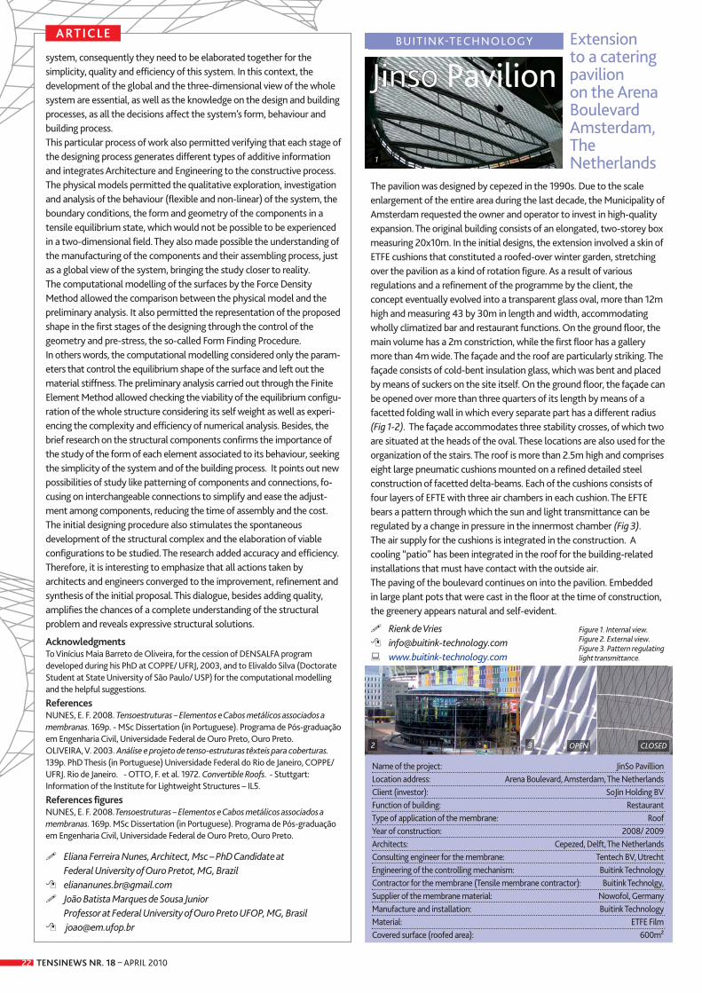
TENSINEWS NR. 18 – APRIL 201022
The pavilion was designed by cepezed in the 1990s. Due to the scaleenlargement of the entire area during the last decade, the Municipality ofAmsterdam requested the owner and operator to invest in high-qualityexpansion. The original building consists of an elongated, two-storey boxmeasuring 20x10m. In the initial designs, the extension involved a skin ofETFE cushions that constituted a roofed-over winter garden, stretchingover the pavilion as a kind of rotation figure. As a result of variousregulations and a refinement of the programme by the client, theconcept eventually evolved into a transparent glass oval, more than 12mhigh and measuring 43 by 30m in length and width, accommodatingwholly climatized bar and restaurant functions. On the ground floor, themain volume has a 2m constriction, while the first floor has a gallerymore than 4m wide. The façade and the roof are particularly striking. Thefaçade consists of cold-bent insulation glass, which was bent and placedby means of suckers on the site itself. On the ground floor, the façade canbe opened over more than three quarters of its length by means of afacetted folding wall in which every separate part has a different radius(Fig 1-2). The façade accommodates three stability crosses, of which twoare situated at the heads of the oval. These locations are also used for theorganization of the stairs. The roof is more than 2.5m high and compriseseight large pneumatic cushions mounted on a refined detailed steelconstruction of facetted delta-beams. Each of the cushions consists offour layers of EFTE with three air chambers in each cushion. The EFTEbears a pattern through which the sun and light transmittance can beregulated by a change in pressure in the innermost chamber (Fig 3). The air supply for the cushions is integrated in the construction. Acooling “patio” has been integrated in the roof for the building-relatedinstallations that must have contact with the outside air. The paving of the boulevard continues on into the pavilion. Embedded in large plant pots that were cast in the floor at the time of construction,the greenery appears natural and self-evident.
� Rienk de Vries � [email protected] � www.buitink-technology.com
ARTICLE
system, consequently they need to be elaborated together for thesimplicity, quality and efficiency of this system. In this context, thedevelopment of the global and the three-dimensional view of the wholesystem are essential, as well as the knowledge on the design and buildingprocesses, as all the decisions affect the system’s form, behaviour andbuilding process.This particular process of work also permitted verifying that each stage ofthe designing process generates different types of additive informationand integrates Architecture and Engineering to the constructive process. The physical models permitted the qualitative exploration, investigationand analysis of the behaviour (flexible and non-linear) of the system, theboundary conditions, the form and geometry of the components in atensile equilibrium state, which would not be possible to be experiencedin a two-dimensional field. They also made possible the understanding ofthe manufacturing of the components and their assembling process, justas a global view of the system, bringing the study closer to reality. The computational modelling of the surfaces by the Force DensityMethod allowed the comparison between the physical model and thepreliminary analysis. It also permitted the representation of the proposedshape in the first stages of the designing through the control of thegeometry and pre-stress, the so-called Form Finding Procedure. In others words, the computational modelling considered only the param-eters that control the equilibrium shape of the surface and left out thematerial stiffness. The preliminary analysis carried out through the FiniteElement Method allowed checking the viability of the equilibrium configu-ration of the whole structure considering its self weight as well as experi-encing the complexity and efficiency of numerical analysis. Besides, thebrief research on the structural components confirms the importance ofthe study of the form of each element associated to its behaviour, seekingthe simplicity of the system and of the building process. It points out newpossibilities of study like patterning of components and connections, fo-cusing on interchangeable connections to simplify and ease the adjust-ment among components, reducing the time of assembly and the cost. The initial designing procedure also stimulates the spontaneousdevelopment of the structural complex and the elaboration of viableconfigurations to be studied. The research added accuracy and efficiency.Therefore, it is interesting to emphasize that all actions taken byarchitects and engineers converged to the improvement, refinement andsynthesis of the initial proposal. This dialogue, besides adding quality,amplifies the chances of a complete understanding of the structuralproblem and reveals expressive structural solutions.
AcknowledgmentsTo Vinícius Maia Barreto de Oliveira, for the cession of DENSALFA programdeveloped during his PhD at COPPE/ UFRJ, 2003, and to Elivaldo Silva (DoctorateStudent at State University of São Paulo/ USP) for the computational modellingand the helpful suggestions.
ReferencesNUNES, E. F. 2008. Tensoestruturas – Elementos e Cabos metálicos associados amembranas. 169p. - MSc Dissertation (in Portuguese). Programa de Pós-graduaçãoem Engenharia Civil, Universidade Federal de Ouro Preto, Ouro Preto.OLIVEIRA, V. 2003. Análise e projeto de tenso-estruturas têxteis para coberturas.139p. PhD Thesis (in Portuguese) Universidade Federal do Rio de Janeiro, COPPE/UFRJ. Rio de Janeiro. - OTTO, F. et al. 1972. Convertible Roofs. - Stuttgart:Information of the Institute for Lightweight Structures – IL5.
References figuresNUNES, E. F. 2008.Tensoestruturas – Elementos e Cabos metálicos associados amembranas. 169p. MSc Dissertation (in Portuguese). Programa de Pós-graduaçãoem Engenharia Civil, Universidade Federal de Ouro Preto, Ouro Preto.
� Eliana Ferreira Nunes, Architect, Msc – PhD Candidate at Federal University of Ouro Pretot, MG, Brazil
� [email protected]� João Batista Marques de Sousa Junior
Professor at Federal University of Ouro Preto UFOP, MG, Brasil� [email protected]
JJiinnssoo PavilionExtension to a cateringpavilion on the ArenaBoulevardAmsterdam,The Netherlands
BUITINK-TECHNOLOGY
Name of the project: JinSo PavillionLocation address: Arena Boulevard, Amsterdam, The NetherlandsClient (investor): SoJin Holding BVFunction of building: RestaurantType of application of the membrane: RoofYear of construction: 2008/ 2009Architects: Cepezed, Delft, The NetherlandsConsulting engineer for the membrane: Tentech BV, Utrecht Engineering of the controlling mechanism: Buitink TechnologyContractor for the membrane (Tensile membrane contractor): Buitink Technolgy, Supplier of the membrane material: Nowofol, GermanyManufacture and installation: Buitink TechnologyMaterial: ETFE FilmCovered surface (roofed area): 600m²
CLOSEDOPEN
1
2 3
Figure 1. Internal view.Figure 2. External view.Figure 3. Pattern regulatinglight transmittance.
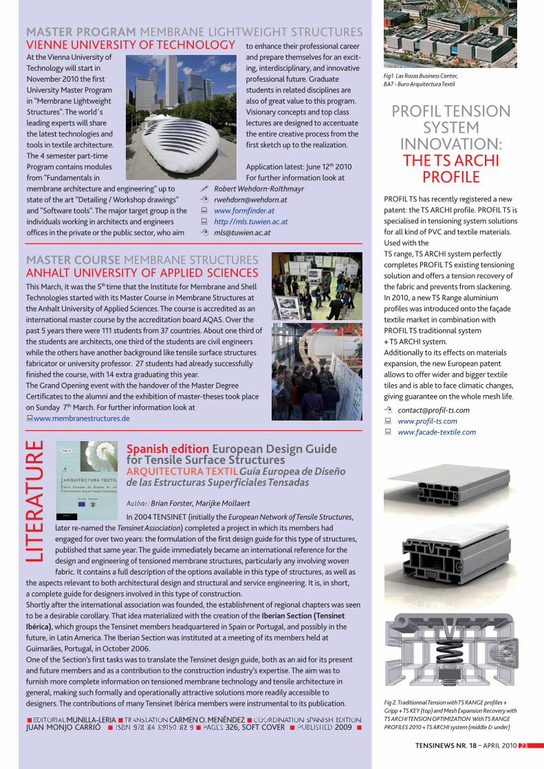
TENSINEWS NR. 18 – APRIL 2010 23
PROFIL TENSION SYSTEM
INNOVATION:THE TS ARCHI
PROFILEPROFIL TS has recently registered a newpatent: the TS ARCHI profile. PROFIL TS isspecialised in tensioning system solutionsfor all kind of PVC and textile materials.Used with the TS range, TS ARCHI system perfectlycompletes PROFIL TS existing tensioningsolution and offers a tension recovery ofthe fabric and prevents from slackening. In 2010, a new TS Range aluminiumprofiles was introduced onto the façadetextile market in combination withPROFIL TS traditionnal system + TS ARCHI system. Additionally to its effects on materialsexpansion, the new European patentallows to offer wider and bigger textiletiles and is able to face climatic changes,giving guarantee on the whole mesh life.
� [email protected] � www.profil-ts.com � www.facade-textile.com
Spanish edition European Design Guide for Tensile Surface Structures ARQUITECTURA TEXTIL Guía Europea de Diseño de las Estructuras Superficiales Tensadas
Brian Forster, Marijke Mollaert
In 2004 TENSINET (initially the European Network of Tensile Structures,later re-named the Tensinet Association) completed a project in which its members hadengaged for over two years: the formulation of the first design guide for this type of structures,published that same year. The guide immediately became an international reference for thedesign and engineering of tensioned membrane structures, particularly any involving wovenfabric. It contains a full description of the options available in this type of structures, as well as
the aspects relevant to both architectural design and structural and service engineering. It is, in short, a complete guide for designers involved in this type of construction.Shortly after the international association was founded, the establishment of regional chapters was seento be a desirable corollary. That idea materialized with the creation of the Iberian Section (TensinetIbérica), which groups the Tensinet members headquartered in Spain or Portugal, and possibly in thefuture, in Latin America. The Iberian Section was instituted at a meeting of its members held atGuimarães, Portugal, in October 2006. One of the Section’s first tasks was to translate the Tensinet design guide, both as an aid for its presentand future members and as a contribution to the construction industry’s expertise. The aim was tofurnish more complete information on tensioned membrane technology and tensile architecture ingeneral, making such formally and operationally attractive solutions more readily accessible todesigners. The contributions of many Tensinet Ibérica members were instrumental to its publication.
■ MUNILLA-LERIA ■ CARMEN O. MENÉNDEZ ■JUAN MONJO CARRIÓ ■ ■ 326, SOFT COVER ■ 2009 ■
LITE
RATU
REAt the Vienna University ofTechnology will start in November 2010 the firstUniversity Master Programin "Membrane LightweightStructures". The world´sleading experts will sharethe latest technologies andtools in textile architecture.The 4 semester part-timeProgram contains modulesfrom "Fundamentals inmembrane architecture and engineering" up tostate of the art "Detailing / Workshop drawings"and "Software tools". The major target group is theindividuals working in architects and engineers offices in the private or the public sector, who aim
to enhance their professional careerand prepare themselves for an excit-ing, interdisciplinary, and innovativeprofessional future. Graduate students in related disciplines arealso of great value to this program.Visionary concepts and top class lectures are designed to accentuatethe entire creative process from thefirst sketch up to the realization.
Application latest: June 12th 2010For further information look at
� Robert Wehdorn-RoIthmayr� [email protected] � www.formfinder.at � http://mls.tuwien.ac.at� [email protected]
This March, it was the 5th time that the Institute for Membrane and ShellTechnologies started with its Master Course in Membrane Structures atthe Anhalt University of Applied Sciences. The course is accredited as aninternational master course by the accreditation board AQAS. Over thepast 5 years there were 111 students from 37 countries. About one third ofthe students are architects, one third of the students are civil engineerswhile the others have another background like tensile surface structuresfabricator or university professor. 27 students had already successfullyfinished the course, with 14 extra graduating this year.The Grand Opening event with the handover of the Master DegreeCertificates to the alumni and the exhibition of master-theses took placeon Sunday 7th March. For further information look at�www.membranestructures.de
Fig1. Las Rozas Business Center, BAT - Buro Arquitectura Textil
Fig 2. Traditionnal Tension with TS RANGE profiles +Gripp + TS KEY (top) and Mesh Expansion Recovery withTS ARCHI TENSION OPTIMIZATION With TS RANGEPROFILES 2010 + TS ARCHI system (middle & under)
MASTER PROGRAM MEMBRANE LIGHTWEIGHT STRUCTURES VIENNE UNIVERSITY OF TECHNOLOGY
MASTER COURSE MEMBRANE STRUCTURES ANHALT UNIVERSITY OF APPLIED SCIENCES