a study on ferroresonance mitigation techniques for power
TRANSCRIPT
A Study on Ferroresonance Mitigation Techniques for Power Transformer
S. I. Kim, B. C. Sung, S. N. Kim, Y. C. Choi, H. J. Kim
Abstract--This paper presents a comprehensive study on the
ferroresonance mitigation techniques for a power transformer by
performing four feasible solutions as follows: (a) an increase of
capacity of shunt capacitance at the transformer primary side (b)
a change of the transformer saturation characteristics with the
low flux density (c) an insertion of the capacitor bank at the
transformer secondary side (d) an installation of the resistive load
bank at the transformer secondary side. In order to verify the
methods mentioned above, the EMTP-RV (Electromagnetic
Transients Program – Restructured Version) software is used to
model the each study cases. This paper also introduces some
reviews on isolating a power transformer using a disconnector,
investigating the operation of surge arresters against
ferroresonance overvoltage, and examining the variation of the
residual flux of the iron core in a power transformer.
Keywords: ferroresonance, mitigation technique, power trans-
former, EMTP-RV.
I. INTRODUCTION
ERRORESONANCE is a non-linear resonance
phenomenon which can be caused in a low loss electric
circuit containing non-linear inductance, capacitance, and a
voltage source. Non-linear inductance consists of power
transformers, inductive voltage transformers and so on.
Capacitance is made of cables, long transmission lines, power
transformers, and grading capacitors in circuit breakers.
Contrary to inductive voltage transformers, the failure of
power transformers due to ferroresonance overvoltages has not
yet reported [1]. The sustained overvoltage under
ferroresonance, however, can accelerate the deterioration of
the insulation materials in power transformers and result in the
failure of surge arresters. In order to avoid unexpected
equipment damages, the effective and practical techniques
should be studied.
An extensive literature on ferroresonance provides a
number of countermeasures against ferroresonance in power
transformers. Among these measures, four feasible solutions
are examined in order to prevent the actual ferroresonance for
the 25 MVA 380 / 13.8 kV YNyn0 auxiliary power
transformer which is presented in Chapter II. This paper also
introduces some reviews on isolating a power transformer
from the grid during ferroresonance using a disconnector
between them, investigating the effectiveness of the surge
S. I. Kim, B. C. Sung, S. N. Kim, Y. C. Choi, and H. J. Kim are with Hyundai
Heavy Industries Co., Ltd., Korea (e-mail: [email protected]).
Paper submitted to the International Conference on Power Systems
Transients (IPST2015) in Cavtat, Croatia June 15-18, 2015
arresters for the actual ferroresonance, and examining the
variation of the residual flux of the iron core in a power
transformer.
II. FERRORESONANCE OF POWER TRANSFORMER WITH
CIRCUIT BREAKER GRADING CAPACITORS
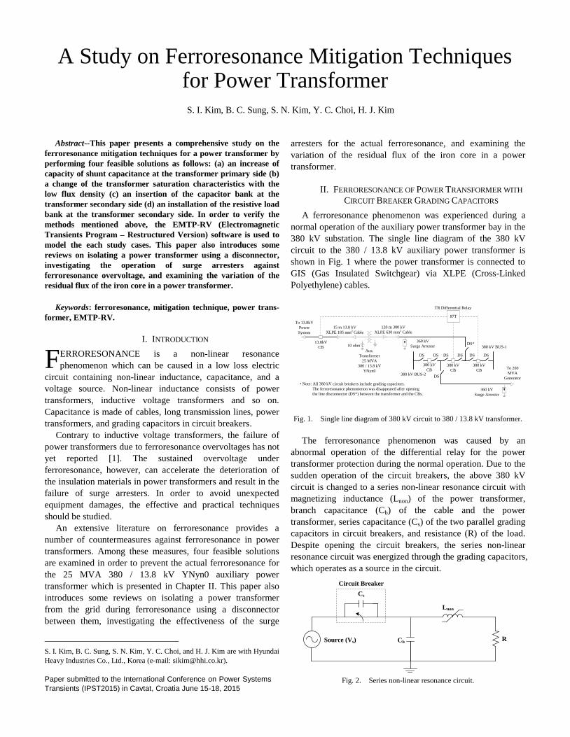
A ferroresonance phenomenon was experienced during a
normal operation of the auxiliary power transformer bay in the
380 kV substation. The single line diagram of the 380 kV
circuit to the 380 / 13.8 kV auxiliary power transformer is
shown in Fig. 1 where the power transformer is connected to
GIS (Gas Insulated Switchgear) via XLPE (Cross-Linked
Polyethylene) cables.
Aux.
Transformer
25 MVA
380 / 13.8 kV
YNyn0
380 kV BUS-1
380 kV
CB380 kV BUS-2
87T
120 m 380 kV
XLPE 630 mm2 Cable
13.8kV
CB
TR Differential Relay
15 m 13.8 kV
XLPE 185 mm2 Cable
360 kV
Surge Arrester
360 kV
Surge Arrester
To 260
MVA
Generator
• Note: All 380 kV circuit breakers include grading capacitors.
The ferroresonance phenomenon was disappeared after opening
the line disconnector (DS*) between the transformer and the CBs.
380 kV
CB
380 kV
CB
10 ohm
To 13.8kV
Power
System
DS
DS DS DS DS DS DS
DS*
Fig. 1. Single line diagram of 380 kV circuit to 380 / 13.8 kV transformer.
The ferroresonance phenomenon was caused by an
abnormal operation of the differential relay for the power
transformer protection during the normal operation. Due to the
sudden operation of the circuit breakers, the above 380 kV
circuit is changed to a series non-linear resonance circuit with
magnetizing inductance (Lnon) of the power transformer,
branch capacitance (Cb) of the cable and the power
transformer, series capacitance (Cs) of the two parallel grading
capacitors in circuit breakers, and resistance (R) of the load.
Despite opening the circuit breakers, the series non-linear
resonance circuit was energized through the grading capacitors,
which operates as a source in the circuit.
Cb
Cs
Lnon
Circuit Breaker
Source (Vs) R
Fig. 2. Series non-linear resonance circuit.
F
Very loud humming sound with overvoltage and over
exciting current (over flux) was detected during the
ferroresonance phenomenon. The ferroresonance phenomenon
was disappeared after opening the line disconnector (DS* of
Fig. 1) between the transformer and the circuit breakers. The
distorted voltage waveforms with amplitude of 1.28 ~ 1.55 pu
and over exciting current waveforms were recorded.
In order to simulate the ferroresonance phenomenon and
find its countermeasures, the circuit of the 380 kV substation is
modeled using the EMTP-RV software. The on-site
parameters and estimated data for the 380 kV substation are
applied to this model.
The simulation model consists of a source, a series
capacitor, a branch capacitor, a non-linear inductor, and a
resistor. The source voltage is 395 kV (1.04 pu) and the source
impedance is not considered due to the lack of data. Grading
capacitors in the circuit breakers and phase-to-ground
capacitance of the power system components are modeled as
the combination of the series capacitor and the branch
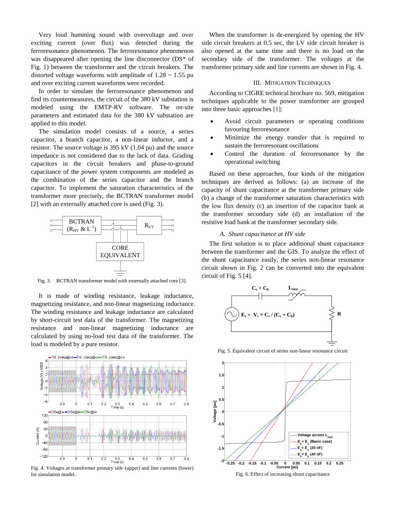
capacitor. To implement the saturation characteristics of the
transformer more precisely, the BCTRAN transformer model
[2] with an externally attached core is used (Fig. 3).
BCTRAN
(RHV & L-1)RLV
CORE
EQUIVALENT
Fig. 3. BCTRAN transformer model with externally attached core [3].
It is made of winding resistance, leakage inductance,
magnetizing resistance, and non-linear magnetizing inductance.
The winding resistance and leakage inductance are calculated
by short-circuit test data of the transformer. The magnetizing
resistance and non-linear magnetizing inductance are
calculated by using no-load test data of the transformer. The
load is modeled by a pure resistor.
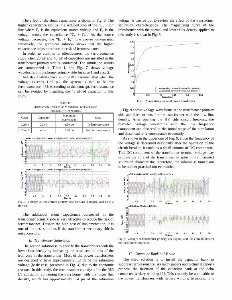
Fig. 4. Voltages at transformer primary side (upper) and line currents (lower)
for simulation model.
When the transformer is de-energized by opening the HV
side circuit breakers at 0.5 sec, the LV side circuit breaker is
also opened at the same time and there is no load on the
secondary side of the transformer. The voltages at the
transformer primary side and line currents are shown in Fig. 4.
III. MITIGATION TECHNIQUES
According to CIGRE technical brochure no. 569, mitigation
techniques applicable to the power transformer are grouped
into three basic approaches [1]:
Avoid circuit parameters or operating conditions
favouring ferroresonance
Minimize the energy transfer that is required to
sustain the ferroresonant oscillations
Control the duration of ferroresonance by the
operational switching
Based on these approaches, four kinds of the mitigation
techniques are derived as follows: (a) an increase of the
capacity of shunt capacitance at the transformer primary side
(b) a change of the transformer saturation characteristics with
the low flux density (c) an insertion of the capacitor bank at
the transformer secondary side (d) an installation of the
resistive load bank at the transformer secondary side.
A. Shunt capacitance at HV side
The first solution is to place additional shunt capacitance
between the transformer and the GIS. To analyze the effect of
the shunt capacitance easily, the series non-linear resonance
circuit shown in Fig. 2 can be converted into the equivalent
circuit of Fig. 5 [4].
Cs + Cb Lnon
Es = Vs × Cs / (Cs + Cb) R
Fig. 5. Equivalent circuit of series non-linear resonance circuit
-0.25 -0.2 -0.15 -0.1 -0.05 0 0.05 0.1 0.15 0.2 0.25-2
-1.5
-1
-0.5
0
0.5
1
1.5
2
Current [pu]
Vo
lta
ge
[p
u]
Voltage across Lnon
Es+ E
c (Basic case)
Es+ E
c (20 nF)
Es+ E
c (40 nF)
Fig. 6. Effect of increasing shunt capacitance
The effect of the shunt capacitance is shown in Fig. 6. The
higher capacitance results in a reduced slop of the “Es + Ec”
line where Es is the equivalent source voltage and Ec is the
voltage across the capacitance “Cs + Cb”. As the source
voltage decreases, the “Es + Ec” line moves downwards.
Intuitively, the graphical solution shows that the higher
capacitance helps to reduce the risk of ferroresonance.
In order to confirm its effectiveness, the ferroresonance
study when 20 nF and 40 nF of capacitors are installed at the
transformer primary side is conducted. The simulation results
are summarized in Table I, and Fig. 7 shows voltage
waveforms at transformer primary side for case 1 and case 2.
Industry analysts have empirically assumed that when the
voltage exceeds 1.25 pu, the system is said to be “in
ferroresonance” [5]. According to this concept, ferroresonance
can be avoided by installing the 40 nF of capacitor in this
study.
TABLE I
SIMULATION RESULTS OF MAXIMUM OVERVOLTAGE
FOR SHUNT CAPACITORS
Cases Capacitor Maximum
overvoltage State
Case 1 20 nF 1.50 pu In ferroresonance
Case 2 40 nF 0.78 pu Non ferroresonance
Fig. 7. Voltages at transformer primary side for Case 1 (upper) and Case 2
(lower).
The additional shunt capacitance connected in the
transformer primary side is very effective to reduce the risk of
ferroresonance. Despite the high cost of implementation, it is
one of the best solutions if the transformer secondary side is
not accessible.
B. Transformer Saturation
The second solution is to specify the transformers with the
lower flux density by increasing the cross section area of the
iron core in the transformer. Most of the power transformers
are designed to have approximately 1.2 pu of the saturation
voltage (basic case, presented in Fig. 4) due to the economic
reasons. In this study, the ferroresonance analysis for the 380
kV substation containing the transformer with the lower flux
density, which has approximately 1.4 pu of the saturation
voltage, is carried out to review the effect of the transformer
saturation characteristics. The magnetizing curve of the
transformer with the normal and lower flux density applied to
this study is shown in Fig. 8.
0 0.05 0.1 0.15 0.2 0.251
1.05
1.1
1.15
1.2
1.25
1.3
1.35
1.4
1.45
Current [pu]
Vo
lta
ge
[p
u]
Magnetizing curve with normal flux density
Magnetizing curve with lower flux density
Fig. 8. Magnetizing curve of power transformer
Fig. 9 shows voltage waveforms at the transformer primary
side and line currents for the transformer with the low flux
density. After opening the HV side circuit breakers, the
distorted voltage waveforms with the low frequency
component are observed at the initial stage of the simulation
and these lead to ferroresonance eventually.
As shown in the upper one of Fig. 9, since the frequency of
the voltage is decreased drastically after the operation of the
circuit breaker, it contains a small amount of DC component.
This DC component of the transformer terminal voltage may
saturate the core of the transformer in spite of its increased
saturation characteristic. Therefore, the solution is turned out
to be neither practical nor economical.
Fig. 9. Voltages at transformer primary side (upper) and line currents (lower)
for transformer saturation.
C. Capacitor Bank at LV side
The third solution is to install the capacitor bank to
suppress ferroresonance. As many papers and technical reports
propose the insertion of the capacitor bank at the delta
connected tertiary winding [6]. This can only be applicable to
the power transformers with tertiary winding terminals. It is

considered that the capacitor bank is located at the transformer
secondary side in the study because the transformer applied to
this study does not have tertiary winding.
In the simulation, the capacitor banks are increased from
2 % to 20 % (0.5 MVar ~ 5 MVar) of the capacity of the
transformer. The simulation results are summarized in Table II.
Voltage waveforms for Case 1, Case 2, Case 3, and Case 4 are
presented in Fig. 10 and Fig. 11 to understand the effect of the
capacitor bank clearly.
TABLE II
SIMULATION RESULTS OF MAXIMUM OVERVOLTAGE
FOR CAPACITOR BANKS
Cases Capacitor bank
capacity
Maximum
overvoltage State
Case 1 5.0 MVar 0.27 pu Non ferroresonance
Case 2 3.0 MVar 0.41 pu Non ferroresonance
Case 3 1.0 MVar 0.87 pu Non ferroresonance
Case 4 0.5 MVar 1.87 pu In ferroresonance
Fig. 10 shows voltage waveforms at the transformer
primary side when the transformer is connected to 12 % and
20 % of the capacitor bank. It can be observed that the high
capacity of the capacitor bank is very effective on the
suppression of ferroresonance.
Fig. 10. Voltages at transformer primary side for Case 1 (upper) and Case 2
(lower).
Fig. 11. Voltages at transformer primary side for Case 3 (upper) and Case 4
(lower).
Fig. 11 shows voltage waveforms at transformer primary
side when the transformer is connected to 2 % and 4 % of the
capacitor bank. Ferroresonance can be avoided by installing
the capacitor bank with the capacity of 4 % of its capacity.
This countermeasure has the disadvantages such as its
higher cost and the possibility of explosion in practice. In
other words, the capacitor bank at the transformer secondary
side can significantly reduce the risk of ferroresonance,
however it also has disadvantages as well.
D. Resistive Load Bank at LV Side
The last solution is to place the suitable resistive load bank
to the transformer secondary side. It increases the loss of the
series non-linear resonance circuit. Fig. 12 shows the graphical
solution of the series non-linear resonance circuit without the
resistor for the basic case where P1 is a non-ferroresonant
stable operation point, P2 is an unstable operating point, and P3
is a ferroresonant stable point [7]. In case of the circuit without
the resistance, there are three intersection points with “|EL -
Ec|” line and “Es” line which contains a ferroresonant stable
point (P3). Thus, the ferroresonance phenomenon can occur in
this condition.
0 0.05 0.1 0.150
0.5
1
1.5
Current [pu]
Vo
lta
ge
[p
u]
Ec
Voltage across Lnon
(EL)
|EL- E
c|
Es
P1
P2
P3
Fig. 12. Graphical solution of series non-linear ferroresonance circuit without
resistance [7].
0 0.05 0.1 0.150
0.5
1
1.5
Current [pu]
Vo
lta
ge
[p
u]
Voltage across Lnon
(EL)
|EL- E
c|
P1 ((E
s)2-(RI)
2)
Ec
Us / R
Fig. 13. Graphical solution of series non-linear ferroresonance circuit with
resistance [1].
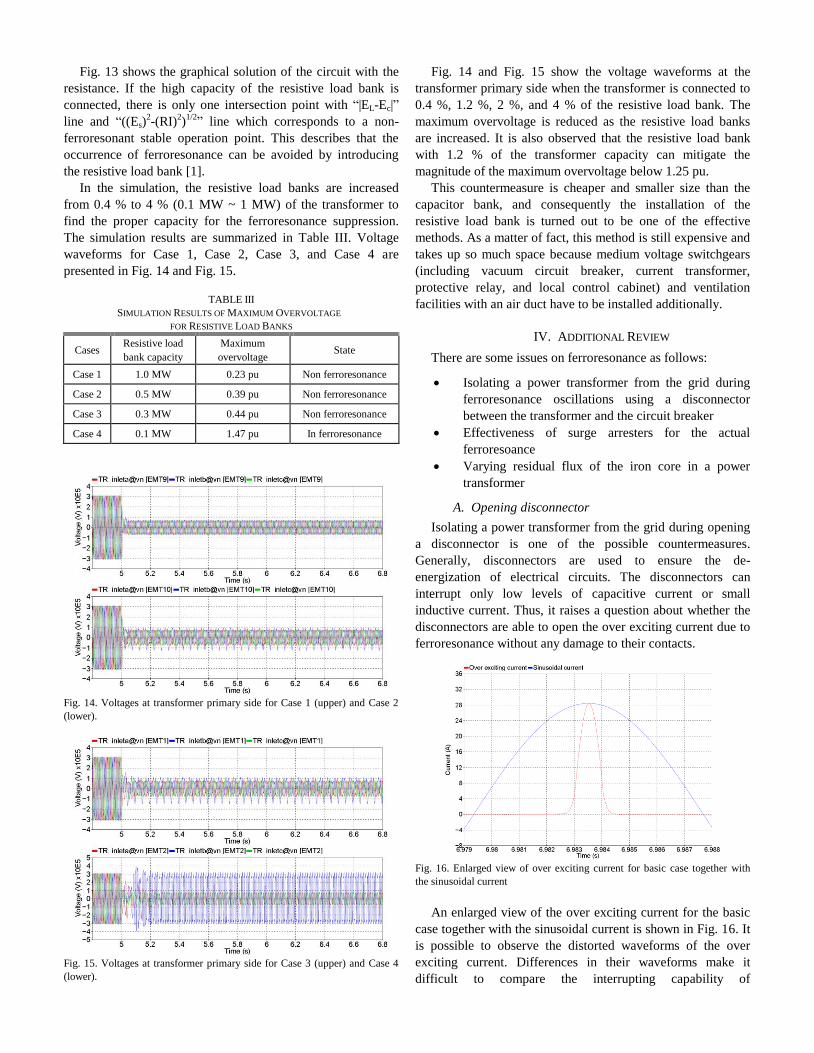
Fig. 13 shows the graphical solution of the circuit with the
resistance. If the high capacity of the resistive load bank is
connected, there is only one intersection point with “|EL-Ec|”
line and “((Es)2-(RI)
2)
1/2” line which corresponds to a non-
ferroresonant stable operation point. This describes that the
occurrence of ferroresonance can be avoided by introducing
the resistive load bank [1].
In the simulation, the resistive load banks are increased
from 0.4 % to 4 % (0.1 MW ~ 1 MW) of the transformer to
find the proper capacity for the ferroresonance suppression.
The simulation results are summarized in Table III. Voltage
waveforms for Case 1, Case 2, Case 3, and Case 4 are
presented in Fig. 14 and Fig. 15.
TABLE III
SIMULATION RESULTS OF MAXIMUM OVERVOLTAGE
FOR RESISTIVE LOAD BANKS
Cases Resistive load
bank capacity
Maximum
overvoltage State
Case 1 1.0 MW 0.23 pu Non ferroresonance
Case 2 0.5 MW 0.39 pu Non ferroresonance
Case 3 0.3 MW 0.44 pu Non ferroresonance
Case 4 0.1 MW 1.47 pu In ferroresonance
Fig. 14. Voltages at transformer primary side for Case 1 (upper) and Case 2
(lower).
Fig. 15. Voltages at transformer primary side for Case 3 (upper) and Case 4
(lower).
Fig. 14 and Fig. 15 show the voltage waveforms at the
transformer primary side when the transformer is connected to
0.4 %, 1.2 %, 2 %, and 4 % of the resistive load bank. The
maximum overvoltage is reduced as the resistive load banks
are increased. It is also observed that the resistive load bank
with 1.2 % of the transformer capacity can mitigate the
magnitude of the maximum overvoltage below 1.25 pu.
This countermeasure is cheaper and smaller size than the
capacitor bank, and consequently the installation of the
resistive load bank is turned out to be one of the effective
methods. As a matter of fact, this method is still expensive and
takes up so much space because medium voltage switchgears
(including vacuum circuit breaker, current transformer,
protective relay, and local control cabinet) and ventilation
facilities with an air duct have to be installed additionally.
IV. ADDITIONAL REVIEW
There are some issues on ferroresonance as follows:
Isolating a power transformer from the grid during
ferroresonance oscillations using a disconnector
between the transformer and the circuit breaker
Effectiveness of surge arresters for the actual
ferroresoance
Varying residual flux of the iron core in a power
transformer
A. Opening disconnector
Isolating a power transformer from the grid during opening
a disconnector is one of the possible countermeasures.
Generally, disconnectors are used to ensure the de-
energization of electrical circuits. The disconnectors can
interrupt only low levels of capacitive current or small
inductive current. Thus, it raises a question about whether the
disconnectors are able to open the over exciting current due to
ferroresonance without any damage to their contacts.
Fig. 16. Enlarged view of over exciting current for basic case together with
the sinusoidal current
An enlarged view of the over exciting current for the basic
case together with the sinusoidal current is shown in Fig. 16. It
is possible to observe the distorted waveforms of the over
exciting current. Differences in their waveforms make it
difficult to compare the interrupting capability of
disconnectors for the over exciting current. However, it can be
inferred from Fig. 16 that even if the amplitude of the over
exciting current is higher than the capability of disconnectors,
disconnectors can interrupt the over exciting current due to its
short-duration peak current.
The actual ferroresonance for the 380 kV substation
described in Chapter II can be disappeared by opening the
disconnector without the damage to their contacts. It might
have been that the disconnector operated at the low current.
In the 230 kV substation, the failure of disconnector
contacts due to large arcing during interrupting the
ferroresonant current has been reported recently. It resulted in
flashover in the 230 kV GIS.
Opening disconnector is the easiest way of reducing
ferroresonance. However, extra attention must be paid to
suppress the ferroresonance because a normal disconnector is
capable of disconnecting only small amount of current.
Therefore, further research is needed for disconnestor’s
interrupting capacity of ferroresonant current.
B. Surge arrester operation
In case of the actual ferroresonance, the surge arresters
installed at the 380 kV substation did not operate for the
ferroresonance overvoltage. It can be checked through whether
the counters of the surge arresters operated or not.
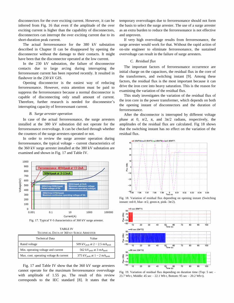
In order to review the surge arrester operation during
ferroresonance, the typical voltage – current characteristics of
the 360 kV surge arrester installed at the 380 kV substation are
examined and shown in Fig. 17 and Table IV.
Fig. 17. Typical V-I characteristics of 360 kV surge arrester.
TABLE IV
TECHNICAL DATA OF 360 KV SURGE ARRESTER
Technical Data Value
Rated voltage 509 kVpeak at 2 ~ 2.5 mApeak
Min. operating voltage and current 562 kVpeak at 3 mApeak
Max. cont. operating voltage & current 375 kVpeak at 1 ~ 2 mApeak
Fig. 17 and Table IV show that the 360 kV surge arresters
cannot operate for the maximum ferroresonance overvoltage
with amplitude of 1.55 pu. The result of this review
corresponds to the IEC standard [8]. It states that the
temporary overvoltages due to ferroresonance should not form
the basis to select the surge arrester. The use of a surge arrester
as an extra burden to reduce the ferroresonance is not effective
and unproven.
If very high overvoltage results from ferroresonance, the
surge arrester would work for that. Without the rapid action of
on-site engineer to eliminate ferroresonance, the sustained
overvoltage can result in the failure of surge arresters.
C. Residual flux
The important factors of ferroresonance occurrence are
initial charge on the capacitors, the residual flux in the core of
the transformers, and switching instant [9]. Among these
factors, the residual flux is the most important because it can
drive the iron core into heavy saturation. This is the reason for
examining the variation of the residual flux.
This study investigates the variation of the residual flux of
the iron core in the power transformer, which depends on both
the opening instant of disconnectors and the duration of
ferroresonance.
After the disconnector is interrupted by different voltage
phase at 0, π/2, π, and 3π/2 radians, respectively, the
amplitudes of the residual flux are calculated. Fig 18 shows
that the switching instant has no effect on the variation of the
residual flux.
Fig. 18. Variation of residual flux depending on opening instant (Switching
instant: red-0, blue- π/2, green-π, pink- 3π/2).
Fig. 19. Variation of residual flux depending on duration time (Top: 5 sec –
23.7 Wb∙t, Middle: 45 sec – 22.1 Wb∙t, Bottom: 95 sec – 20.2 Wb∙t).
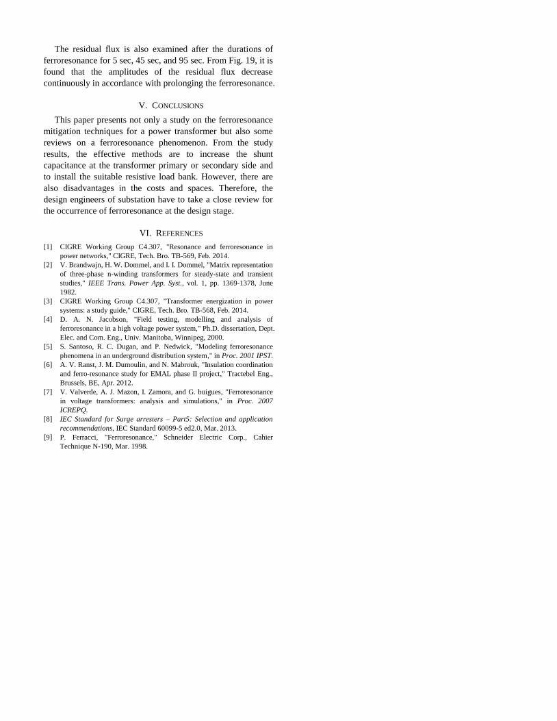
The residual flux is also examined after the durations of
ferroresonance for 5 sec, 45 sec, and 95 sec. From Fig. 19, it is
found that the amplitudes of the residual flux decrease
continuously in accordance with prolonging the ferroresonance.
V. CONCLUSIONS
This paper presents not only a study on the ferroresonance
mitigation techniques for a power transformer but also some
reviews on a ferroresonance phenomenon. From the study
results, the effective methods are to increase the shunt
capacitance at the transformer primary or secondary side and
to install the suitable resistive load bank. However, there are
also disadvantages in the costs and spaces. Therefore, the
design engineers of substation have to take a close review for
the occurrence of ferroresonance at the design stage.
VI. REFERENCES
[1] CIGRE Working Group C4.307, "Resonance and ferroresonance in
power networks," CIGRE, Tech. Bro. TB-569, Feb. 2014.
[2] V. Brandwajn, H. W. Dommel, and I. I. Dommel, "Matrix representation
of three-phase n-winding transformers for steady-state and transient
studies," IEEE Trans. Power App. Syst., vol. 1, pp. 1369-1378, June
1982.
[3] CIGRE Working Group C4.307, "Transformer energization in power
systems: a study guide," CIGRE, Tech. Bro. TB-568, Feb. 2014.
[4] D. A. N. Jacobson, "Field testing, modelling and analysis of
ferroresonance in a high voltage power system," Ph.D. dissertation, Dept.
Elec. and Com. Eng., Univ. Manitoba, Winnipeg, 2000.
[5] S. Santoso, R. C. Dugan, and P. Nedwick, "Modeling ferroresonance
phenomena in an underground distribution system," in Proc. 2001 IPST.
[6] A. V. Ranst, J. M. Dumoulin, and N. Mabrouk, "Insulation coordination
and ferro-resonance study for EMAL phase II project," Tractebel Eng.,
Brussels, BE, Apr. 2012.
[7] V. Valverde, A. J. Mazon, I. Zamora, and G. buigues, "Ferroresonance
in voltage transformers: analysis and simulations," in Proc. 2007
ICREPQ.
[8] IEC Standard for Surge arresters – Part5: Selection and application
recommendations, IEC Standard 60099-5 ed2.0, Mar. 2013.
[9] P. Ferracci, "Ferroresonance," Schneider Electric Corp., Cahier
Technique N-190, Mar. 1998.