a systems engineering capability maturity model, version 1 · a systems engineering capability...
TRANSCRIPT
HandbookSECMM-94-04CMU/SEI-94-HB-04
Carnegie Mellon UniversitySoftware Engineering Institute
A Systems EngineeringCapability Maturity Model,Version 1.0
SE - CMM
Systems Engineering Improvement
Systems EngineeringCapability Maturity Model Project
December 1994


Software Engineering InstituteCarnegie Mellon University
Pittsburgh, Pennsylvania 15213
Unlimited distribution subject to the copyright.
HandbookCMU/SEI-94-HB-04
A Systems Engineering Capability Maturity Model, Version 1.0
R. Bate, S. Garcia, J. Armitage, K. Cusick,
R. Jones, D. Kuhn, I. Minnich,
H., Pierson, T. Powell, A. Reichner

This report was prepared for the
SEI Joint Program OfficeHQ ESC/AXS5 Eglin StreetHanscom AFB, MA 01731-2116
The ideas and findings in this report should not be construed as an official DoD position. It is published in theinterest of scientific and technical information exchange.
FOR THE COMMANDER
(signature on file)
Thomas R. Miller, Lt Col, USAFSEI Joint Program Office
This work is sponsored by the U.S. Department of Defense.
Copyright © 1994 by Carnegie Mellon University.
Permission to reproduce this document and to prepare derivative works from this document for internal use isgranted, provided the copyright and “No Warranty” statements are included with all reproductions and derivativeworks.
Requests for permission to reproduce this document or to prepare derivative works of this document for externaland commercial use should be addressed to the SEI Licensing Agent.
NO WARRANTY
THIS CARNEGIE MELLON UNIVERSITY AND SOFTWARE ENGINEERING INSTITUTE MATERIALIS FURNISHED ON AN “AS-IS” BASIS. CARNEGIE MELLON UNIVERSITY MAKES NO WARRAN-TIES OF ANY KIND, EITHER EXPRESSED OR IMPLIED, AS TO ANY MATTER INCLUDING, BUT NOTLIMITED TO, WARRANTY OF FITNESS FOR PURPOSE OR MERCHANTIBILITY, EXCLUSIVITY, ORRESULTS OBTAINED FROM USE OF THE MATERIAL. CARNEGIE MELLON UNIVERSITY DOESNOT MAKE ANY WARRANTY OF ANY KIND WITH RESPECT TO FREEDOM FROM PATENT,TRADEMARK, OR COPYRIGHT INFRINGEMENT.
This work was created in the performance of Federal Government Contract Number F19628-95-C-0003 withCarnegie Mellon University for the operation of the Software Engineering Institute, a federally funded researchand development center. The Government of the United States has a royalty-free government-purpose license touse, duplicate, or disclose the work, in whole or in part and in any manner, and to have or permit others to do so,for government purposes pursuant to the copyright license under the clause at 52.227-7013.
This document is available through Research Access, Inc., 800 Vinial Street, Pittsburgh, PA 15212. Phone: 1-800-685-6510. FAX: (412) 321-2994. RAI also maintains a World Wide Web home page. The URL ishttp://www.rai.com
Copies of this document are available through the National Technical Information Service (NTIS). For informa-tion on ordering, please contact NTIS directly: National Technical Information Service, U.S. Department ofCommerce, Springfield, VA 22161. Phone: (703) 487-4600.
This document is also available through the Defense Technical Information Center (DTIC). DTIC provides accessto and transfer of scientific and technical information for DoD personnel, DoD contractors and potential contrac-tors, and other U.S. Government agency personnel and their contractors. To obtain a copy, please contact DTICdirectly: Defense Technical Information Center / 8725 John J. Kingman Road / Suite 0944 / Ft. Belvoir, VA22060-6218. Phone: (703) 767-8222 or 1-800 225-3842.]
Use of any trademarks in this report is not intended in any way to infringe on the rights of the trademark holder.
SECMM-94-04|CMU/SEI-94-HB-4 v1.0 i
Table of Contents
Acknowledgments ...................................................................................... iiiTo the Reader ............................................................................................ v
Part 1: Overview InformationChapter 1: Introduction.................................................................................................. 1-1
1.1 About this Document............................................................................ 1-21.2 About the SE-CMM Project................................................................... 1-4
Chapter 2: Overview of the SE-CMM.............................................................................. 2-12.1 SE-CMM Foundations .......................................................................... 2-22.2 Key Concepts of the SE-CMM............................................................... 2-82.3 SE-CMM Architecture Description.......................................................... 2-142.4 Process Capability Aspect of the SE-CMM............................................... 2-212.5 Capability Levels................................................................................. 2-252.6 Domain Aspect of the SE-CMM............................................................. 2-27
Chapter 3: Using the SE-CMM ...................................................................................... 3-13.1 Many Usage Contexts ........................................................................... 3-23.2 Using the SE-CMM to Support Appraisal ................................................ 3-43.3 Using the SE-CMM to Support Process Improvement ................................ 3-73.4 Using the SE-CMM in Process Design .................................................... 3-12
Part 2: The SE-CMM PracticesChapter 4: The SE-CMM Generic & Base Practices............................................................ 4-1Chapter 4A: Generic Practices........................................................................................... 4-2
Capability Level 0 - Not Performed ............................................................. 4-3Capability Level 1 - Performed Informally .................................................... 4-4Capability Level 2 - Planned and Tracked...................................................... 4-5Capability Level 3 - Well Defined ............................................................... 4-10Capability Level 4 - Quantitatively Controlled............................................... 4-13Capability Level 5 - Continuously Improving ............................................... 4-14
Chapter 4B: Process Areas/Base Practices............................................................................ 4-16Process Area Format................................................................................... 4-17PA 01: Analyze Candidate Solutions ............................................................ 4-19PA 02: Derive and Allocate Requirements...................................................... 4-23PA 03: Develop Physical Architecture .......................................................... 4-33PA 04: Integrate Disciplines ....................................................................... 4-39PA 05: Integrate System ............................................................................ 4-45PA 06: Understand Customer Needs and Expectations ...................................... 4-51PA 07: Verify and Validate System .............................................................. 4-56PA 08: Ensure Quality............................................................................... 4-62PA 09: Manage Configurations ................................................................... 4-67PA 10: Manage Risk................................................................................. 4-72PA 11: Monitor and Control Technical Effort................................................. 4-77PA 12: Plan Technical Effort ...................................................................... 4-81PA 13: Define Organization's Systems Engineering Process.............................. 4-91PA 14: Improve Organization's Systems Engineering Processes......................... 4-95PA 15: Manage Product Line Evolution........................................................ 4-98PA 16: Manage Systems Engineering Support Environment............................. 4-102PA 17: Manage Systems Engineering Training............................................... 4-108
Part 3: AppendicesAppendix A: Change History and Change Request Form................................. A-3Appendix B: Approved Model Requirements................................................. A-7Appendix C: References............................................................................ A-21Appendix D: Systems Engineering Glossary................................................. A-25

i i SECMM-94-04|CMU/SEI-94-HB-4 v1.0
Tables and Figures
Tables:Table 1-1. SE-CMM Work Products....................................................................... 1-3Table 1-2. SE-CMM Authors................................................................................ 1-5Table 2-1. Components of the Process Capability Aspect of the SE-CMM.................... 2-15Table 2-2. SE-CMM Capability Levels................................................................... 2-17Table 2-3. Components of the Domain Aspect of the SE-CMM .................................. 2-19Table 2-4. SE-CMM Process Areas........................................................................ 2-19Table 3-1. Customer Base..................................................................................... 3-3Table 3-2. Process Improvement Principles in the SE-CMM....................................... 3-10Table A-1. Change History Table ........................................................................... A-3Table A-2. Traceability Matrix............................................................................... A-17
Figures:Figure 1-1. SE-CMM Project Organization............................................................... 1-4Figure 2-1. Critical Dimensions of Organizational Capability....................................... 2-2Figure 2-2. Model Architecture ............................................................................... 2-5Figure 2-3. Focus of the SE-CMM.......................................................................... 2-7Figure 2-4. Diagram of SE-CMM Architecture .......................................................... 2-14Figure 2-5. Improvement Path for Process Capability ................................................. 2-22Figure 2-6. SE-CMM Process Areas........................................................................ 2-27Figure 2-7. Iteration.............................................................................................. 2-32Figure 2-8. Sequencing Concepts Example................................................................ 2-34Figure 2-9. Example Process Showing Iteration, Concurrency, and Recursion.................. 2-35Figure 3-1. Determining Process Capability .............................................................. 3-5Figure 3-2. Factors for Successful Process Design...................................................... 3-13Figure 4-1. Process Area Format............................................................................. 4-18
SECMM-94-04|CMU/SEI-94-HB-4 v1.0 iii
Acknowledgments
Participants The model herein described is the work of many individuals fromindustry, academia, and government. Their spirit of cooperation andwillingness to give of themselves in a joint pursuit of excellence wasremarkable. Although a few are mentioned below who fulfilled specificreview roles, we are aware that, beyond those whose names we know,there are many who supported the points of contacts who turned inreview comments or otherwise participated. A listing of all knownparticipants, their affiliation and role(s) is too extensive to be includedhere. A copy is available, by request, from the project.
The level of individual participation varied from a few hours to full time(and more). But, the project could not have been successfullycompleted without the active contribution of everyone concerned, andtheir efforts are truly appreciated.
Keyreviewerswhoreturnedcomments
The authors would like to extend their thanks to the key reviewers whoreturned comments on intermediate releases of the model description,including those who participated in our workshops. Their insights werealways valued and considered seriously by the authors, and theircontributions extended the reach of the authors far beyond their ownexperience. This group includes: A. Dniestrowski, A. Shumskas, A.Sutton, A. Wilbur, B. Andrews, B. Mar, C. Giffen, C. Montgomery,C. Zumba, C.L. Nelson, D. Francis, D. Gunther, D. Jester, D.Kinney, D. Marquet, D. McCauley, D. McConnell, D. Preklas, D.Zaugg, E. Cherian, E.R. Anderson, G. Hingle, G. Lake, G. Pandelios,H. Jesse, H. Lee, H. Wilson, J. Burleson, J. Cooper, J. Gross, J.Harbison, J. Huller, J. Jaggers, J. Lake, J. Marciniak, J. Miller, J.Moon, J. Porter, J. Velman, J.P. Jones, K. Arunski, K. Ferraloio, K.Jones, L. Bloodsworth, L. Gallagher, L. Nelson, M. Brown, M.Carroll, M. Falat, M. Ginsberg, M. Klien, M. Konrad, M. Merrill, M.Ross, M. Ross, M. Ward-Callan, N. Sanford, P. James, R. Ade, R.Bechtold, R. Czizik, R. Daniel, R. Elkin, R. Nakahara, R. Ragano, R.Sabouhi, R. Schmidt, S. Friedenthal, S. Levie, S. McCammon, T.Carpenter, T. Concannon, T. Kudlick, T. Parker, T. Robertson, T.Sweeney, W. Hefley, W. Mackey, W. Oran, W. Peterson, K. Kirlin,and Y. Trsonstad.
continued on next page

iv SECMM-94-04|CMU/SEI-94-HB-4 v1.0
Acknowledgments, Continued
Pilotappraisals
The authors would also like to extend their sincere thanks to theorganizations who made the first set of pilot appraisals for the SE-CMMsuch successes, from the viewpoint of both gathering data about themodel, and learning about how the SE-CMM architecture facilitatesappraisal. Over 100 individuals participated in 3 appraisals scatteredbetween Texas Instruments, Hughes, and United Technologies. Thesponsors of these appraisals deserve special recognition for being earlyadopters of the SE-CMM: John Grimm from Texas Instruments, SteveCunningham from Hughes, and Kenneth Rosen from UnitedTechnologies. Their cooperation, insight, and patience contributedsignificantly to the quality of the first public version of the SE-CMM.
SE-CMMsteeringgroupmembers
The Steering Group for the SE-CMM Project has provided bothtraditional management oversight functions and extensive technical andstrategic input to the project, and their individual and collectedcontributions to the project are appreciated beyond measure. The namesand organization for the SE-CMM Steering Group members in thecollaboration are provided in the table below:
Organization ContactsDepartment of Defense John Burt
Hughes Aircraft Company Paul Stevens, Ph.D.
Lockheed Corporation Chris Caren, Ph.D.
Loral Federal Systems Company Virginia Lentz
Loral Space & Range Systems Dorothy McKinney
National Institute of Standards andTechnology
Roger Martin
National Council on Systems Engineering Don Crocker
Software Engineering Institute Floyd Hollister
Software Productivity Consortium Art Pyster, Ph.D.
Texas Instruments, Incorporated Merle Whatley
SE-CMM Collaboration Contacts

SECMM-94-04|CMU/SEI-94-HB-4 v1.0 v
To the Reader
What is theSE-CMM?
The Systems Engineering Capability Maturity Model (SE-CMM)describes the essential elements of an organization's systemsengineering process that must exist to ensure good systems engineering.It does not specify a particular process or sequence. In addition, theSE-CMM provides a reference for comparing actual systemsengineering practices against these essential elements.
The SE-CMM Model Description provides an overall description of theprinciples and architecture upon which the SE-CMM is based, anexecutive overview of the model, suggestions for appropriate use of themodel, the practices included in the model, and a description of theattributes of the model. It also includes the requirements used todevelop the model.
Why was itdeveloped?
Success in market-driven and contractually negotiated market areas isoften determined by how efficiently an organization translates customerneeds into a product that effectively meets those needs. Good systemsengineering is key to that activity, and the SE-CMM provides a way tomeasure and enhance performance in that arena.
Why issystemsengineeringimportant?
The following classic example backs up the need for good systemsengineering.
The Tacoma Narrows bridge was built to connect Tacoma with theOlympic peninsula in Washington State. It was a very long suspensionbridge with a flexible roadway. In 1940 it collapsed because of strongwinds in the Narrows that started an aerodynamic oscillation that finallybuckled the roadway.
In the engineering investigations that followed the disaster, it emergedthat the engineers who designed the bridge had not done aerodynamicinvestigations of the design, because none of them were familiar withthe techniques and it was not realized that the wind would have suchstrong dynamic effects.
One of the advantages of systems engineering based on a definedprocess is the precept of fully investigating the nature of theenvironment around the system and the effects that the environment willhave on the system under all circumstances. Systems engineers usingprocesses based on SE-CMM practices are not any more likely to knowthe parameters of a particular problem, but are likely to followdisciplined investigative methods that draw out the risk areas of asystem.
continued on next page

vi SECMM-94-04|CMU/SEI-94-HB-4 v1.0
To the Reader, Continued
What is thescope of theSE-CMM?
This first version of the SE-CMM starts with determination of the users'needs and extends through verification of the initial product. This firstversion focuses on process characteristics. Given sufficient communitysupport, planned expansions will encompass the remaining productlife-cycle activities and include both personnel and technologycharacteristics.
How shouldit be used?
The SE-CMM is designed to help organizations improve their practice ofsystems engineering through self-assessment and guidance in theapplication of statistical process control principles. Use of the model forsupplier selection is discouraged.
In conjunction with the model itself, a companion appraisal method hasbeen developed, and will be described in SECMM-94-06|CMU/SEI-94-HB-05, SE-CMM Appraisal Method Description.
Intendedaudience
The SE-CMM is focused on four primary groups, systems engineeringpractitioners from any business sector or government, processdevelopers, individuals charged with appraising how specific systemsengineering organizations implement their systems engineeringprocesses, and systems engineering managers. Persons with five yearsor more of experience as a systems engineering practitioner or managerand exposure to formal methods of organization assessment will benefitmost from the model.
Additionalinformation-projectoffice
If you have any questions about this model or about pilot appraisalsusing this model, please contact the SE-CMM Project. The maintenancesite for the project is the Software Engineering Institute of CarnegieMellon University. The product manager, Suzanne Garcia, may becontacted at
4500 Fifth Ave. (412)268-7625 (voice)Pittsburgh, PA 15213 (412)268-5758 (fax)email: [email protected]
Data rightsassociatedwith the SE-CMM
The SE-CMM collaboration members are committed to encouraging freeuse of the SE-CMM Model Description as a reference for the systemsengineering community. Members have agreed that this and futureversions of this document, when released to the public, will retain theconcept of free access via a permissive copyright notice.
SECMM-94-04|CMU/SEI-94-HB-4 v1.0 1 - 1
Chapter 1: Introduction
Purpose ofthis chapter
The purpose of this chapter is to introduce the reader to the documentand to the SE-CMM Project.
In thischapter
The following table provides a guide to the information found in thischapter.
Topic See Page1.1 About this Document 1-2
1.2 About the SE-CMM Project 1-4

1 - 2 SECMM-94-04|CMU/SEI-94-HB-4 v1.0
1.1 About this Document
Purpose ofthisdocument
This document is designed to acquaint the reader with the SE-CMMProject as a whole and its major product - the Systems EngineeringCapability Maturity Model (SE-CMM). This document is one in a seriesof the SE-CMM Project's work products. It consists of four chaptersand appendices. The document contains only a brief section on usingthe model for appraisal. Please refer to SECMM-94-06|CMU/SEI-94-HB-05, SE-CMM Appraisal Method Description, for details in this area.
Basicorganization
This document contains four chapters plus appendices:
• Introduction• Overview of the SE-CMM• Using the SE-CMM• The SE-CMM Base and Generic Practices
These chapters are described in the blocks below.
Chapter 1:Introduction
This chapter provides the document overview and a brief description ofthe model, the need it is designed to meet, who wrote it, and how theinitial version has been constructed to fit economic and time constraints.
Chapter 2:Overview
This chapter introduces the model and provides an overview of therequirements it is intended to satisfy. It introduces basic concepts thatare key to understanding the details and architecture of the model. Italso introduces the two-sided architecture of the model: the domain-specific side and the capability side. These and other underlyingconstructs and conventions used in expressing the model are explainedto help readers understand and use the model.
Chapter 3:Using theSE-CMM
This chapter provides information that will be useful to individualsinterested in adopting the model and adapting it to differentorganizational situations and contexts.
continued on next page

SECMM-94-04|CMU/SEI-94-HB-4 v1.0 1 - 3
1.1 About this Document, Continued
Chapter 4:SE-CMMPractices
This chapter contains a specific, comprehensive description of themodel. In the domain-specific side of the discussion, base practices,which are characteristics considered essential to successful systemsengineering, are grouped into specific process areas (PAs). Eachprocess area is described in detail. In the capability side of thediscussion, generic practices, which are characteristics of how well thebase practices are performed, are discussed. The concepts of increasingprocess capability are also described in the capability part of the chapter.
Appendices The appendices include a change history for the document, a changerequest form, the requirements for the model description, the references,and a glossary of the terms used in project documents.
Relatedproducts
In addition to this document, the SE-CMM Project plans to produce thefollowing documents for public release in early 1995 via themaintenance site for the SE-CMM Project, Carnegie MellonUniversity's Software Engineering Institute.
Identifier Name Description
SECMM-94-06CMU/SEI-94-HB-05
SE-CMMAppraisalMethodDescription
The SE-CMM Appraisal Method Descriptionprovides a description of the appraisalmethod developed for use with the SE-CMMwhen evaluating adherence to the principlesand/or practices of the SE-CMM. It alsocontains the appraisal method requirements.
SECMM-94-08CMU/SEI-94-TR-25
SE-CMMPilotAppraisalReport
The SE-CMM Pilot Appraisal Reportdescribes the results of piloting activity forthe systems engineering community to useas they adopt and work with the SE-CMMand its associated appraisal method.
SECMM-94-09CMU/SEI-94-TR-26
RelationshipsBetween theSE-CMM andOther Products
The SE-CMM relationships documentpresents information on relationshipsbetween the process areas/common featuresof the SE-CMM and other products ofinterest to the SE-CMM author group. Thefirst version includes relationships to the AirForce Software Development CapabilityEvaluation, IEEE P1220, draft Mil-Std-499b, and the Capability Maturity Model forSoftware, v1.1.
Table 1-1. SE-CMM Work Products

1 - 4 SECMM-94-04|CMU/SEI-94-HB-4 v1.0
1.2 About the SE-CMM Project
Projecthistory
The Systems Engineering Capability Maturity Model (SE-CMM) wasinstituted as a response to industry requests for assistance incoordinating and publishing a model that would foster improvement inthe systems engineering process. In July 1993 Dr. Roger Bate, the SE-CMM chief architect, presented an approach to developing a SystemsEngineering Capability Maturity Model to potential industry participants.The SE-CMM collaboration was subsequently formed, and specificproject goals and requirements were defined by the SE-CMM steeringgroup. Task completion was set at December 1994.
Projectorganizationchart
The following diagram illustrates the project organization chart. It isdiscussed in the blocks below.
Author
Author
Author
Author
OffsiteSupport
ProjectLeader
SteeringGroup
WorkshopParticipants
ChiefArchitect
Key Reviewers
CorrespondenceGroup
ProjectLibrarian
SEI Support
• Admin Support• Cmpt. Facilities• Info Mngmt.• Event Coord.
Industrial Collaboration
NCOSE
Federal Government • Lockheed• Hughes• Loral• SEI• SPC• TI
AppraisalMethodTeam
Base Practices
Team
Figure 1-1. SE-CMM Project Organization
continued on next page
SECMM-94-04|CMU/SEI-94-HB-4 v1.0 1 - 5
1.2 About the SE-CMM Project, Continued
SE-CMMProjectcomposition
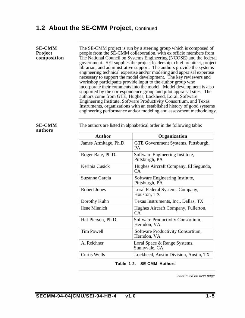
The SE-CMM project is run by a steering group which is composed ofpeople from the SE-CMM collaboration, with ex officio members fromThe National Council on Systems Engineering (NCOSE) and the federalgovernment. SEI supplies the project leadership, chief architect, projectlibrarian, and administrative support. The authors provide the systemsengineering technical expertise and/or modeling and appraisal expertisenecessary to support the model development. The key reviewers andworkshop participants provide input to the author group whoincorporate their comments into the model. Model development is alsosupported by the correspondence group and pilot appraisal sites. Theauthors come from GTE, Hughes, Lockheed, Loral, SoftwareEngineering Institute, Software Productivity Consortium, and TexasInstruments, organizations with an established history of good systemsengineering performance and/or modeling and assessment methodology.
SE-CMMauthors
The authors are listed in alphabetical order in the following table:
Author OrganizationJames Armitage, Ph.D. GTE Government Systems, Pittsburgh,
PA
Roger Bate, Ph.D. Software Engineering Institute,Pittsburgh, PA
Kerinia Cusick Hughes Aircraft Company, El Segundo,CA
Suzanne Garcia Software Engineering Institute,Pittsburgh, PA
Robert Jones Loral Federal Systems Company,Houston, TX
Dorothy Kuhn Texas Instruments, Inc., Dallas, TX
Ilene Minnich Hughes Aircraft Company, Fullerton,CA
Hal Pierson, Ph.D. Software Productivity Consortium,Herndon, VA
Tim Powell Software Productivity Consortium,Herndon, VA
Al Reichner Loral Space & Range Systems,Sunnyvale, CA
Curtis Wells Lockheed, Austin Division, Austin, TX
Table 1-2. SE-CMM Authors
continued on next page
1 - 6 SECMM-94-04|CMU/SEI-94-HB-4 v1.0
1.2 About the SE-CMM Project, Continued
Incorpo-ratingcommunityfeedback
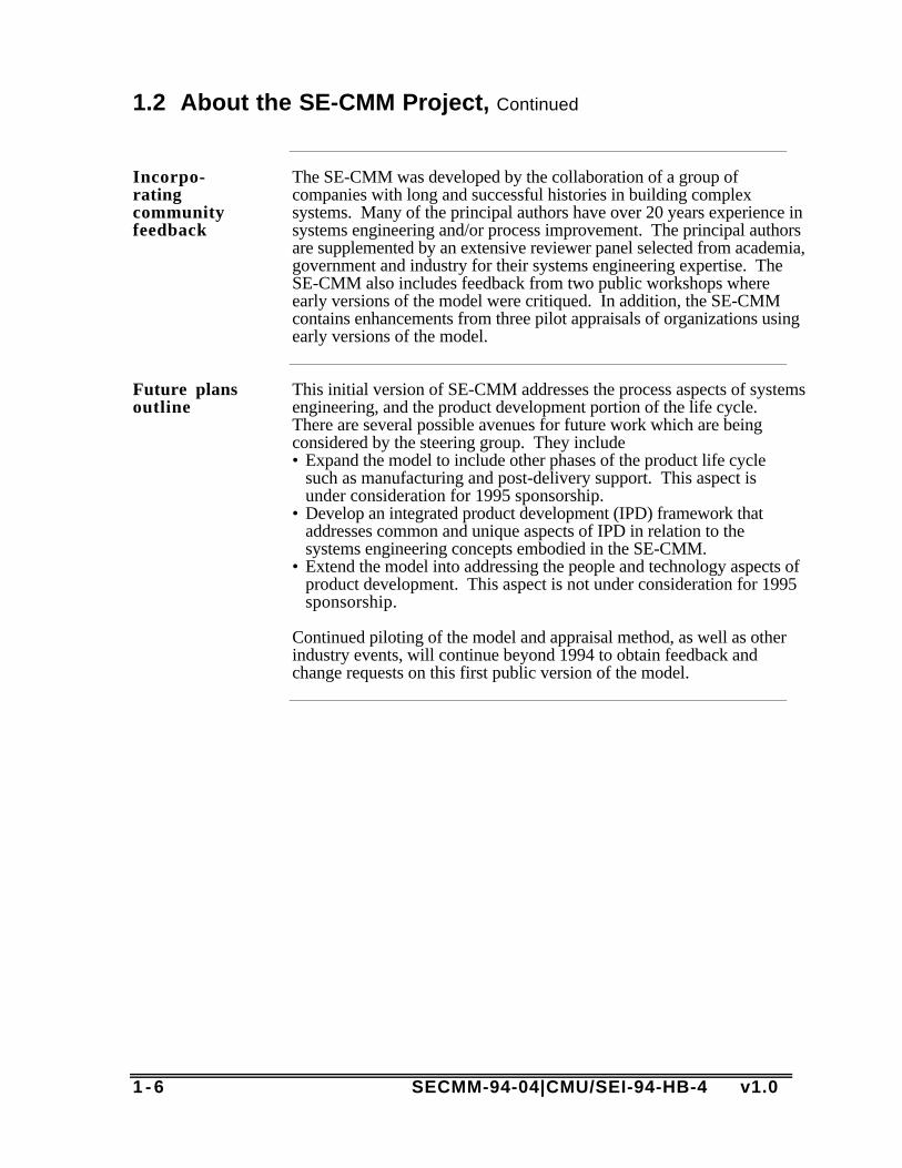
The SE-CMM was developed by the collaboration of a group ofcompanies with long and successful histories in building complexsystems. Many of the principal authors have over 20 years experience insystems engineering and/or process improvement. The principal authorsare supplemented by an extensive reviewer panel selected from academia,government and industry for their systems engineering expertise. TheSE-CMM also includes feedback from two public workshops whereearly versions of the model were critiqued. In addition, the SE-CMMcontains enhancements from three pilot appraisals of organizations usingearly versions of the model.
Future plansoutline
This initial version of SE-CMM addresses the process aspects of systemsengineering, and the product development portion of the life cycle.There are several possible avenues for future work which are beingconsidered by the steering group. They include• Expand the model to include other phases of the product life cycle
such as manufacturing and post-delivery support. This aspect isunder consideration for 1995 sponsorship.
• Develop an integrated product development (IPD) framework thataddresses common and unique aspects of IPD in relation to thesystems engineering concepts embodied in the SE-CMM.
• Extend the model into addressing the people and technology aspects ofproduct development. This aspect is not under consideration for 1995sponsorship.
Continued piloting of the model and appraisal method, as well as otherindustry events, will continue beyond 1994 to obtain feedback andchange requests on this first public version of the model.

SECMM-94-04|CMU/SEI-94-HB-4 v1.0 2 - 1
Chapter 2: Overview of the SE-CMM
Purpose ofthis chapter
The purpose of this chapter is to provide an overview of the conceptsand constructs used in the SE-CMM. It provides information on therequirements that led to the design of the SE-CMM, a description of thearchitecture, and a section on key concepts and terms which are helpfulin understanding the model. It serves as an introduction to the detaileddiscussions of the model in Chapter 4.
In thischapter
The following table provides a guide to the information found in thischapter.
Topic See Page2.1 SE-CMM Foundations 2-2
2.2 Key Concepts of the SE-CMM 2-8
2.3 SE-CMM Architecture Description 2-14
2.4 Capability Aspect of the SE-CMM 2-21
2.5 Capability Levels 2-25
2.6 Domain Aspect of the SE-CMM 2-27

2 - 2 SECMM-94-04|CMU/SEI-94-HB-4 v1.0
2.1 SE-CMM Foundations
Introduction In this section, the fundamental concepts that have guided thedevelopment of the SE-CMM are presented, and the SE-CMM approvedrequirements related to those concepts are cited. The requirementnumber most closely related to the discussion is included at the end ofthe block in parentheses. The complete set of SE-CMM requirements isfound in Appendix B.
Criticaldimensionsof capability
The SE-CMM Project believes that the quality of a product is a directfunction of (at least) the process and technology used to develop theproduct and the capability of the people assigned to do the work (seeFigure 2-1, below). The initial efforts of the project focus on modelingcharacteristics of the process dimension, that is, processes used toimplement and institutionalize sound systems engineering practiceswithin an organization. Subsequent versions of the SE-CMM mayexpand to include other dimensions, i.e., human resources, andengineering technology.
Product/Service
Capability
People TechnologyProcess
Quality
Figure 2-1. Critical Dimensions of Organizational Capability
continued on next page

SECMM-94-04|CMU/SEI-94-HB-4 v1.0 2 - 3
2.1 SE-CMM Foundations, Continued
Whyprocessfirst?
There are several reasons that process is the first dimension oforganizational capability addressed by the SE-CMM. A few of theseinclude• Process is an integrating function for people and technology.• Process focus improves predictability of performance, as well as
performance itself.• Research in improving process capability translates well from other
fields, such as software engineering, to systems engineering (req't4.3.1).
Definitionof systemsengineering
There are dozens of definitions of systems engineering published invarious industry, academic, and government documents that addresssystems engineering topics. Rather than invent an additional definition,the authors chose to adopt the definition found in Army Field Manual770-78, which reads as follows:
Systems engineering is the selective application of scientific andengineering efforts to• transform an operational need into a description of the system
configuration which best satisfies the operational need according to themeasures of effectiveness;
• integrate related technical parameters and ensure compatibility of allphysical, functional, and technical program interfaces in a mannerwhich optimizes the total system definition and design;
• integrate the efforts of all engineering disciplines and specialties intothe total engineering effort. [FM 770-78]
Why thisdefinition?
This definition was adopted over others primarily because it emphasizesthe leadership role of system engineering in integrating other disciplinesand does not contain terminology specific to a particular industrysegment.
Depth andbreadth ofmodelcoverage
SE-CMM coverage extends to, but does not include, various componentimplementation disciplines (e.g., hardware, firmware, and softwaredevelopment) and specialty engineering disciplines. The current versionof the model covers the system life cycle from the customer’sidentification of need through verification of the initial product. (req’ts4.4, 6.1.2).
continued on next page

2 - 4 SECMM-94-04|CMU/SEI-94-HB-4 v1.0
2.1 SE-CMM Foundations, Continued
Specialtyengineeringdisciplines
The SE-CMM does not specifically address specialty engineeringdisciplines such as reliability, human factors engineering, ormanufacturing. There are many such disciplines, and the authorsrecognize that many systems engineers primarily contribute to thesystems development effort via their participation from specialtyviewpoints. The model requires the integration of the engineeringdisciplines and specialties, whichever ones are necessary andappropriate for a particular product development. (req't 4.4)
Relationshipof systemsengineeringto overallprogram/projectmanagement
There is considerable debate within the systems engineering communityas to systems engineering's role within the overall management of aproject or program. Some argue that the systems engineering roleencompasses all the program management functions. Systemsengineering must have sufficient control over all the resources that arecritical to balancing cost, schedule, quality, and functionality objectives.Others argue that the systems engineering role should be subservient toprogram management, to be able to provide the necessary engineeringviewpoint into business decisions. The SE-CMM has taken the latterapproach, although it recognizes that systems engineers commonlyperform extensive program/project management roles in someenvironments. The project management practices expressed in the SE-CMM are those most commonly found as part of the technicalmanagement function of the systems engineer, and those supportingpractices that are critical to the successful performance of systemsengineering regardless of performer (req't 6.1.1, 4.1)
Flexiblearchitecture
The model architecture, shown in Figure 2-2, below, separates thesystems engineering process areas (on the domain side) from the genericcharacteristics (on the capability side) related to increasing processcapability (See Section 2.3 for a more detailed description). Thisarchitecture, which separates domain-specific characteristics fromcapability-related characteristics, was deliberately chosen to enable theuse of process capability criteria in other domain areas, e.g., softwareengineering. It also supports the expansion of the model into specialtyengineering or other component engineering disciplines, should this bedeemed appropriate by the organization using the model.
continued on next page

SECMM-94-04|CMU/SEI-94-HB-4 v1.0 2 - 5
2.1 SE-CMM Foundations, Continued
Diagram ofModelArchitecture
Applied to each Process Area
Systems Engineering Capability Maturity Model Architecture
Domain Capability
Process Area CategoriesEngineering - Project - Organization
1to n
Base Practices
Systems EngineeringProcess Areas
Process CapabilityLevels (6)
1to n
Generic Practices
1 to n
Common Features
Figure 2-2. Model Architecture
Usability The SE-CMM is specifically developed to support an organization's needto assess and improve their systems engineering capability. Thestructure of the model enables a consistent appraisal methodology to beused across diverse process areas. The clear distinction betweenessential, basic systems engineering elements (the domain side) andprocess management-focused elements (the capability side) facilitates anorganized approach to process improvement (req't 6.1.4).
Range ofapplicability
The SE-CMM has a wide range of applicability. The SE-CMM isdeveloped to be valuable to market-driven project environments as wellas negotiated-contract environments. By providing a multipurpose assetthat can be used by (1) individual systems engineering practitioners as aguide, (2) their parent organizations for productivity improvement, and(3) any organization as an eventual supplier selection tool, the SE-CMMmeets the needs of a wide range of users. Applicability will beenhanced by incorporating changes based on field data from eachapplication (req't 4.2, 4.5.1).
continued on next page

2 - 6 SECMM-94-04|CMU/SEI-94-HB-4 v1.0
2.1 SE-CMM Foundations, Continued
Capture andgainleveragefromexisting &emergingstandards
One of the design goals of the SE-CMM effort is to capture the salientconcepts from emerging standards and initiatives (e.g., ISO 9001, draftMil-Std- 499B [now being revised as EIA IS-632], IEEE P1220) andexisting models. For example, the architecture used in the SE-CMM isan adaptation of the ISO SPICE (Software Process ImprovementCapability dEtermination) Baseline Practices Guide (BPG). The BPGis a document under development at the time of this writing, andreferences to it in this text are shown as (SPICE). The version referredto in this document is BPG v1.00a. Information on obtaining the BPGis available from M. Konrad at the SEI in Pittsburgh, PA, or from theSE-CMM Project Office.
SE-CMM-94-09|CMU/SEI-94-TR-26, Relationships between the SE-CMM and Other Products, provides cross-reference informationbetween the SE-CMM and related systems engineering and processstandards (req't 3.2).
Retain CMMinterface
Although the architecture and syntax used to express the SE-CMMmodel are different from those used in the CMM for Software v1.1, itis envisioned that these two models can be used together to effectivelyimprove and assess the systems and software engineering processes of aproject or organization in the future. SECMM-94-09|CMU/SEI-94-TR-26, Relationship between the SE-CMM and Other Products, will containinformation on this interface (req't 6.2.1.2, 3.2).
continued on next page

SECMM-94-04|CMU/SEI-94-HB-4 v1.0 2 - 7
2.1 SE-CMM Foundations, Continued
SE-CMMapplicationenvironment
Figure 2-3 illustrates the intended relationship of the SE-CMM to anorganization's process design and improvement activities. The SE-CMM does not intend to imply or prescribe organizational issues suchas organizational culture, role definitions, or structure, nor is it intendedto imply any particular product or project context. It establishescharacteristics essential to good systems engineering, but does not implyor define a specific, executable process. The major implication of thisapproach is that the SE-CMM, when applied and interpreted within anorganizational and product/project context unique to the business entityusing it, will enhance the resulting systems engineering processeswithout necessarily driving changes in culture or product context. Thisapproach supports the desire to use the SE-CMM in a wide spectrum oforganizational contexts. (req't 4.2)
• Design
• Development
• Validation and Verification
Organization’sSystems Engineering
Process Development
OrganizationalFactors
• Culture• Size• Structure• Roles
Business Factors
• Strategic Focus• Market Pull vs. Technology Push
• Contract vs. Market Driven
• Technology/Method Support
SE-CMM
• Focus Area (Domain)
• Capability• Support
Guidance
Figure 2-3. Focus of the SE-CMM
2 - 8 SECMM-94-04|CMU/SEI-94-HB-4 v1.0
2.2 Key Concepts of the SE-CMM
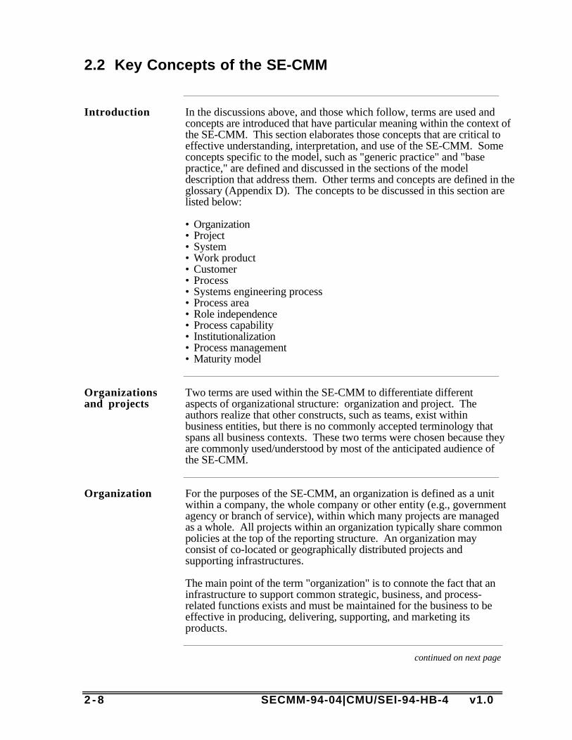
Introduction In the discussions above, and those which follow, terms are used andconcepts are introduced that have particular meaning within the context ofthe SE-CMM. This section elaborates those concepts that are critical toeffective understanding, interpretation, and use of the SE-CMM. Someconcepts specific to the model, such as "generic practice" and "basepractice," are defined and discussed in the sections of the modeldescription that address them. Other terms and concepts are defined in theglossary (Appendix D). The concepts to be discussed in this section arelisted below:
• Organization• Project• System• Work product• Customer• Process• Systems engineering process• Process area• Role independence• Process capability• Institutionalization• Process management• Maturity model
Organizationsand projects
Two terms are used within the SE-CMM to differentiate differentaspects of organizational structure: organization and project. Theauthors realize that other constructs, such as teams, exist withinbusiness entities, but there is no commonly accepted terminology thatspans all business contexts. These two terms were chosen because theyare commonly used/understood by most of the anticipated audience ofthe SE-CMM.
Organization For the purposes of the SE-CMM, an organization is defined as a unitwithin a company, the whole company or other entity (e.g., governmentagency or branch of service), within which many projects are managedas a whole. All projects within an organization typically share commonpolicies at the top of the reporting structure. An organization mayconsist of co-located or geographically distributed projects andsupporting infrastructures.
The main point of the term "organization" is to connote the fact that aninfrastructure to support common strategic, business, and process-related functions exists and must be maintained for the business to beeffective in producing, delivering, supporting, and marketing itsproducts.
continued on next page
SECMM-94-04|CMU/SEI-94-HB-4 v1.0 2 - 9
2.2 Key Concepts of the SE-CMM, Continued
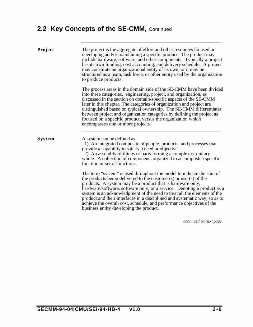
Project The project is the aggregate of effort and other resources focused ondeveloping and/or maintaining a specific product. The product mayinclude hardware, software, and other components. Typically a projecthas its own funding, cost accounting, and delivery schedule. A projectmay constitute an organizational entity of its own, or it may bestructured as a team, task force, or other entity used by the organizationto produce products.
The process areas in the domain side of the SE-CMM have been dividedinto three categories, engineering, project, and organization, asdiscussed in the section on domain-specific aspects of the SE-CMMlater in this chapter. The categories of organization and project aredistinguished based on typical ownership. The SE-CMM differentiatesbetween project and organization categories by defining the project asfocused on a specific product, versus the organization whichencompasses one or more projects.
System A system can be defined as 1) An integrated composite of people, products, and processes thatprovide a capability to satisfy a need or objective. 2) An assembly of things or parts forming a complex or unitarywhole. A collection of components organized to accomplish a specificfunction or set of functions.
The term “system” is used throughout the model to indicate the sum ofthe products being delivered to the customer(s) or user(s) of theproducts. A system may be a product that is hardware only,hardware/software, software only, or a service. Denoting a product as asystem is an acknowledgment of the need to treat all the elements of theproduct and their interfaces in a disciplined and systematic way, so as toachieve the overall cost, schedule, and performance objectives of thebusiness entity developing the product.
continued on next page
2 -10 SECMM-94-04|CMU/SEI-94-HB-4 v1.0
2.2 Key Concepts of the SE-CMM, Continued
Workproduct
Work products are all the documents, files, data, etc., generated in thecourse of performing any process. For example, work products of areview activity might be action item lists, whereas work products of arequirements process might be a database file containing all theelaborated requirements for the product. Rather than call out individualwork products for each process area, the SE-CMM lists "typical workproducts" of a particular base practice, to elaborate further the intendedscope of that base practice. These lists are not to be construed as"mandatory" work products; they are illustrative only, and reflect arange of organizational and product contexts.
Customer A customer is the individual(s) or entity for whom a product isdeveloped or service is rendered and/or the individual or entity who usesthe product or service.
In the context of the SE-CMM, a customer may be either negotiated ornon-negotiated. A negotiated customer is an individual or entity whocontracts with another entity to produce a specific product or set ofproducts according to a set of specifications provided by the customer.A non-negotiated, or market-driven, customer is one of manyindividuals or business entities who have a real or perceived need for aproduct. The customer may also be represented by a customer surrogatesuch as marketing or product focus groups.
In most cases, the SE-CMM uses the term customer in the singular, as agrammatical convenience. However, the SE-CMM does intend toinclude the case of multiple customers.
Note that in the context of the SE-CMM, the individual or entity usingthe product or service is also included in the notion of customer. This isrelevant in the case of negotiated customers, since the entity to whomthe product is delivered is not always the entity or individual who willactually use the product or service. The concept and usage of customerin the SE-CMM is intended to recognize the responsibility of thesystems engineering function to address the entire concept of customer,which includes the user.
continued on next page

SECMM-94-04|CMU/SEI-94-HB-4 v1.0 2 -11
2.2 Key Concepts of the SE-CMM, Continued
Process A process is a set of activities performed to achieve a given purpose.Activities may be performed iteratively, recursively, and/orconcurrently. (These sequencing concepts are discussed in Section2.6). Some activities may transform input work products into outputwork products needed for other activities. The allowable sequence forperforming activities is constrained by the availability of input workproducts and resources and by management control. A full definition ofprocess includes not only the activities and input and output artifacts ofeach activity, but also the mechanisms to control the performance of theactivities. A performed process may follow a defined process, butprobably not exactly. A performed process may also occur without anypre-defined process.
Systemsengineeringprocess
The systems engineering process is defined as a comprehensiveproblem-solving process that is used to
• transform customer needs and requirements into a life-cycle balancedsolution set of system product and process designs,
• generate information for decision makers, and• provide information for the next product development or acquisition
phase.
The problem and success criteria are defined through requirementsanalysis, functional or other type of analysis/allocation, and systemsanalysis. Alternative solutions, evaluation of those alternatives, selectionof the best life-cycle balanced solution, and the description of thesolution are accomplished through synthesis and systems analysis.System development is controlled by integration, verification/validationand configuration management of the process.
This elaborated definition provides a richer context for understandingthe process characteristics under discussion in the SE-CMM.Nevertheless, the systems engineering process is an instance of thegeneral concept of process. Because of its relation to the generalconcept of process, the SE-CMM is able to adopt the generic practicesof the ISO (SPICE) Project (with slight modifications). Thisrelationship between the SE-CMM and general process models isdiscussed in the description of process capability in this chapter.
continued on next page
2 -12 SECMM-94-04|CMU/SEI-94-HB-4 v1.0
2.2 Key Concepts of the SE-CMM, Continued
Process area A process area (PA) is defined as a purpose and set of related systemsengineering process characteristics, which, when performedcollectively, can achieve the defined purpose.
The process areas are composed of base practices, which are mandatorycharacteristics that must exist within an organization's implementedsystems engineering process to be able to claim satisfaction of that PA.
Roleindependence
The process areas of the SE-CMM group practices that, when takentogether, achieve a common purpose. However, the groupings are notintended to imply that all the base practices of a process are necessarilyperformed by a single individual or role. All base practices are writtenin verb-object format (i.e., without a specific subject) so as to minimizethe perception that a particular base practice "belongs to" a particularrole. This is one way in which the syntax of the model supports its useacross a wide spectrum of organizational contexts.
Processcapability
Process capability is defined as the quantifiable range of expected resultsthat can be achieved by following a process. The SE-CMM AppraisalMethod (SAM), which can be used to determine process capabilitylevels for each process area within a project or organization, is basedupon statistical process control concepts which define the use ofprocess capability in many industrial environments. The capability sideof the SE-CMM reflects these concepts and provides guidance inimproving the process capability of the systems engineering practiceswhich are referenced in the domain side of the SE-CMM. (Theappraisal method is further described in Section 3.2)
The capability of an organization's process helps to predict a project'sability to meet its goals. Projects in low capability organizationsexperience wide variations in achieving cost, schedule, functionality,and quality targets. These concepts are further discussed in Chapter 3.
continued on next page

SECMM-94-04|CMU/SEI-94-HB-4 v1.0 2 -13
2.2 Key Concepts of the SE-CMM, Continued
Institution-alization
Institutionalization is the building of infrastructure and corporate culturethat support methods, practices, and procedures so that they are theongoing way of doing business, even after those who originally definedthem are gone. The process capability side of the SE-CMM supportsinstitutionalization by providing practices and a path toward quantitativemanagement and continuous improvement. In this way, the SE-CMMasserts that the organization needs to explicitly support processdefinition, management, and improvement. Institutionalization providesa path toward gaining maximum benefit from a process that exhibitssound systems engineering characteristics.
Processmanagement
Process management is the set of activities and infrastructures used topredict, evaluate, and control the performance of a process. Processmanagement implies that a process is defined (since one cannot predictor control something that is undefined). The focus on processmanagement implies that a project or organization takes into accountboth product- and process-related factors in planning, performance,evaluation, monitoring, and corrective action.
Maturitymodel
A maturity model such as the SE-CMM describes the stages throughwhich processes progress as they are defined, implemented, andimproved. The model provides a guide for selecting processimprovement strategies by determining the current capabilities ofspecific processes and identifying the issues most critical to quality andprocess improvement within a particular domain, such as softwareengineering or systems engineering. A capability maturity model(CMM) may take the form of a reference model to be used as a guide fordeveloping and improving a mature, defined process.
It may also be used to appraise the existence and institutionalization of adefined process that implements the referenced practices. A capabilitymaturity model can cover the processes used to perform the tasks of thespecified domain, (e.g., systems engineering). In addition, a CMM cancover the processes used to ensure effective development and use ofhuman resources, and the insertion of appropriate technology into theproducts and into the tools used to produce the products. The latteraspects have not yet been elaborated for systems engineering.
2 -14 SECMM-94-04|CMU/SEI-94-HB-4 v1.0
2.3 SE-CMM Architecture Description
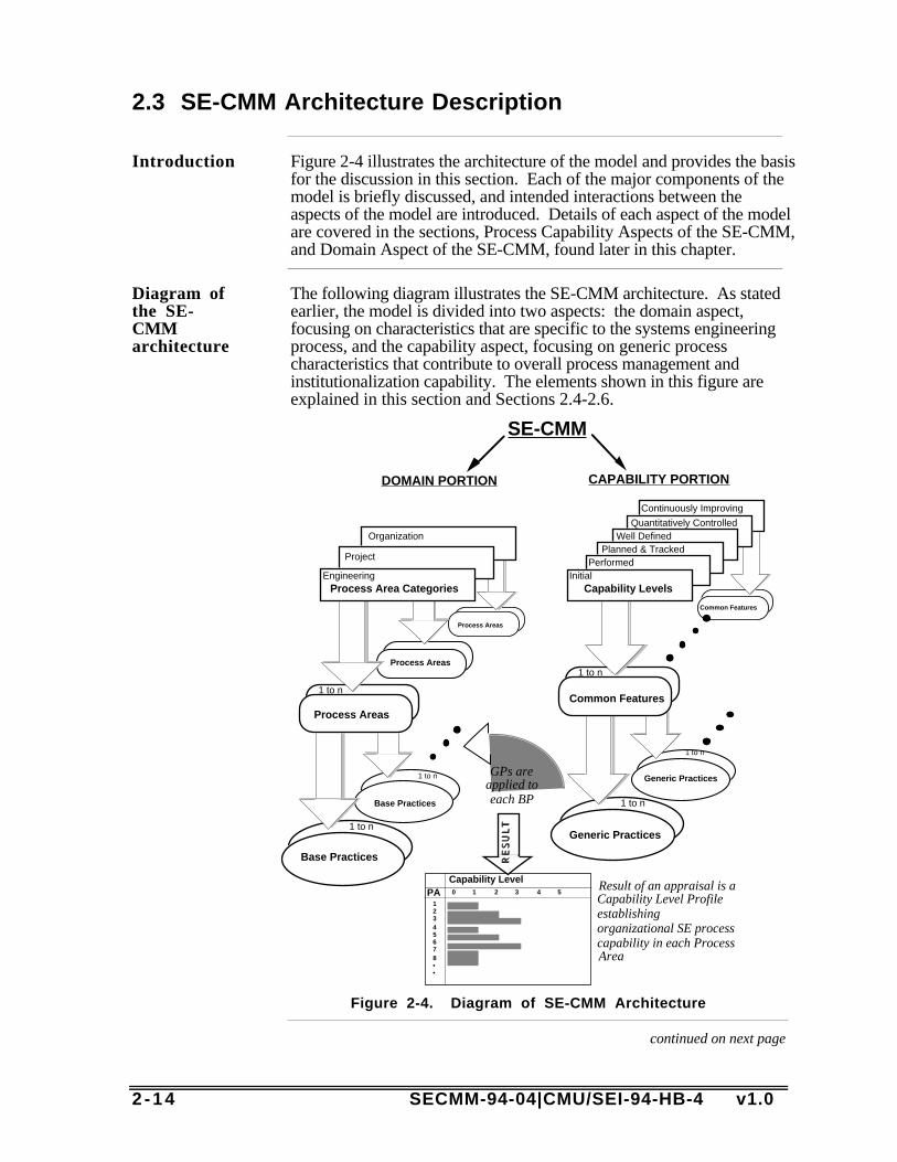
Introduction Figure 2-4 illustrates the architecture of the model and provides the basisfor the discussion in this section. Each of the major components of themodel is briefly discussed, and intended interactions between theaspects of the model are introduced. Details of each aspect of the modelare covered in the sections, Process Capability Aspects of the SE-CMM,and Domain Aspect of the SE-CMM, found later in this chapter.
Diagram ofthe SE-CMMarchitecture
The following diagram illustrates the SE-CMM architecture. As statedearlier, the model is divided into two aspects: the domain aspect,focusing on characteristics that are specific to the systems engineeringprocess, and the capability aspect, focusing on generic processcharacteristics that contribute to overall process management andinstitutionalization capability. The elements shown in this figure areexplained in this section and Sections 2.4-2.6.
Generic Practices
1 to n
Common Features
Base Practices
1 to n
Process Areas
Process Areas
PerformedPlanned & Tracked
Well DefinedQuantitatively Controlled
Continuously Improving
Generic Practices
1 to n
Common Features
1 to n
Organization
Base Practices
1 to n
Process Areas
1 to n
Project
Process Area CategoriesEngineering
Capability LevelsInitial
PACapability Level0 1 2 3 4 5
12345678••
Result of an appraisal is a Capability Level Profile establishing organizational SE process capability in each Process Area
DOMAIN PORTION CAPABILITY PORTION
RESULT
GPs are applied to each BP
SE-CMM
Figure 2-4. Diagram of SE-CMM Architecture
continued on next page

SECMM-94-04|CMU/SEI-94-HB-4 v1.0 2 -15
2.3 SE-CMM Architecture Description, Continued
Dual-patharchitecture
The dual path architecture shown in Figure 2-5 was adopted with onlyslight modification from that chosen by the International Organizationfor Standards (ISO) for their Software Process Improvement CapabilitydEtermination (SPICE) Baseline Practices Guide. It was determinedparticularly applicable to the SE-CMM because it clearly separates basiccharacteristics of the systems engineering process (the domain aspect)from process management and institutionalization characteristics of thesystems engineering process (capability aspect).
Architecturalcomponentsof thecapabilityaspect
The table below contains the basic definitions of the components of thecapability aspect of the SE-CMM. They are further explained in theprocess capability section later in this chapter, as well as elaborated inChapter 4a.
ArchitecturalComponent Definition ExampleCapability Level A set of common
features (sets ofactivities) that worktogether to providea majorenhancement in thecapability toperform a process(SPICE).
2 Planned andTracked
CommonFeature
A set of practicesthat address thesame aspect ofprocessimplementation orinstitutionalization(SPICE).
2.1 Planningperformance
Generic Practice An implementationorinstitutionalizationpractice thatenhances thecapability toperform anyprocess (SPICE).
2.1.3 Documentthe process.Document theapproach toperforming theprocess area instandardsand/orprocedures.
Table 2-1. Components of the Process Capability Aspect of theSE-CMM
continued on next page

2 -16 SECMM-94-04|CMU/SEI-94-HB-4 v1.0
2.3 SE-CMM Architecture Description, Continued
The processcapabilityside of theSE-CMM
The SE-CMM groups process capability in three tiers: capability levels,common features, and generic practices. The capability levels indicateincreasing levels of process maturity and are comprised of one or morecommon features. Each common feature is further detailed by severalgeneric practices.
The common features are designed to describe major shifts in anorganization's characteristic manner of performing work processes (inthis case, the systems engineering domain). Each common feature hasone or more generic practices. With one exception, the generic practicescan be applied to each of the process areas (from the domain side of theSE-CMM) in addition to the basic performance of the practice. The oneexception is the first common feature, "Base practices are performed."
The first capability level has only one generic practice. It is the "do it"generic practice. It asks "does someone in your environment do each ofthe base practices as a part of their process for accomplishing the kind ofwork described in this process area?" Answering "yes" to this questionfor each base practice of a process area means that the process area isinformally performed (level 1).
The subsequent common features have generic practices that helpdetermine how well a project manages and improves each process areaas a whole. The generic practices, described in Chapter 4A, aregrouped to emphasize any major shift in an organization's characteristicmanner of doing systems engineering.
continued on next page

SECMM-94-04|CMU/SEI-94-HB-4 v1.0 2 -17
2.3 SE-CMM Architecture Description, Continued
Capabilitylevels
The table below lists the the capability levels and common features ofthe capability aspect of the SE-CMM:
CapabilityLevel Common Feature
ContinuouslyImproving
• Improving organizational capability• Improving process effectiveness
QuantitativelyControlled
• Establishing measurable quality goals• Objectively managing performance
Well Defined • Defining a standard process• Perform the standard process
Planned andTracked
• Planning performance• Disciplined performance• Verifying performance• Tracking performance
PerformedInformally
• Base practices performed
Table 2-2. SE-CMM Capability Levels
Derived re-quirements
Because the architecture for the model was not expressed in the projectrequirements, there are several areas where, based on the selectedarchitecture, derived requirements were developed that addressparticulars implied by the SPICE architecture. These derivedrequirements reflect mostly issues such as criteria for process areainclusion/exclusion, or criteria for base or generic practices.
Derivedrequire-ments forgenericpractices
The following criteria express the derived requirements for a genericpractice:
• A generic practice applies to all process areas.• Only one generic practice is necessary to achieve a level 1 in each
process area (i.e., generic practice 1.1, Perform the Practice.).• Redundancy with base practices is allowed for special emphasis.• Practices that are essential to a given level of process capability are
included.• Where generic practice topics overlap with process area topics, the
generic practice focuses on the deployment and management aspect ofthe topic.
continued on next page

2 -18 SECMM-94-04|CMU/SEI-94-HB-4 v1.0
2.3 SE-CMM Architecture Description, Continued
The domainaspect of theSE-CMM
The SE-CMM characterizes the systems engineering domain by processareas. Each process area is further detailed by several base practices andexplanatory notes. There are 17 process areas, which are grouped into3 process categories: engineering, project, and organization.
The 17 process areas are designed to describe the major topic areasessential to effective systems engineering within an organization. Inyour home organization, your process will include base practices fromthe process areas that are executed by (or primarily by) individuals in therole of systems engineers. These are the practices primarily grouped inthe "engineering" category. Other of the process areas are likely to beincluded in processes that are executed by people who are performingother roles. These are the "project" and "organization" process areas,which can also be thought of as "support" process areas.
The authors included support process areas in the SE-CMM becauseeffective systems engineering is unlikely unless someone performs thesesupport tasks. For example, it is unlikely that effective systemsengineering will be executed if no one ensures that all the engineeringstaff is working to the same requirement and design baselines at a givenperiod in time (an aspect of the Manage Configurations process area).The point of the SE-CMM is not to indicate "who" does the kinds ofthings described in a particular process area, but to indicate that thework needs to be performed by someone regardless of their role.
continued on next page
SECMM-94-04|CMU/SEI-94-HB-4 v1.0 2 -19
2.3 SE-CMM Architecture Description, Continued
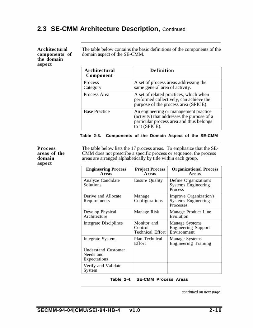
Architecturalcomponents ofthe domainaspect
The table below contains the basic definitions of the components of thedomain aspect of the SE-CMM.
ArchitecturalComponent
Definition
ProcessCategory
A set of process areas addressing thesame general area of activity.
Process Area A set of related practices, which whenperformed collectively, can achieve thepurpose of the process area (SPICE).
Base Practice An engineering or management practice(activity) that addresses the purpose of aparticular process area and thus belongsto it (SPICE).
Table 2-3. Components of the Domain Aspect of the SE-CMM
Processareas of thedomainaspect
The table below lists the 17 process areas. To emphasize that the SE-CMM does not prescribe a specific process or sequence, the processareas are arranged alphabetically by title within each group.
Engineering ProcessAreas
Project ProcessAreas
Organizational ProcessAreas
Analyze CandidateSolutions
Ensure Quality Define Organization'sSystems EngineeringProcess
Derive and AllocateRequirements
ManageConfigurations
Improve Organization'sSystems EngineeringProcesses
Develop PhysicalArchitecture
Manage Risk Manage Product LineEvolution
Integrate Disciplines Monitor andControlTechnical Effort
Manage SystemsEngineering SupportEnvironment
Integrate System Plan TechnicalEffort
Manage SystemsEngineering Training
Understand CustomerNeeds andExpectations
Verify and ValidateSystem
Table 2-4. SE-CMM Process Areas
continued on next page
2 -20 SECMM-94-04|CMU/SEI-94-HB-4 v1.0
2.3 SE-CMM Architecture Description, Continued
Process arearequirements
In developing the model, the authors needed to determine the basis forincluding or not including a process area within the model. Thefollowing criteria were developed for evaluating if a process area shouldbe included:• The process area is essential for effective systems engineering to exist
within an organization.• The process area's purpose is not addressed sufficiently in the generic
practices.• The process area's purpose is considered too important by the author
team to be left out.• The process area assembles key concepts in one area for ease of use.
Derivedrequirementsfor basepractices
The following criteria express the derived requirements for a basepractice:• The base practice is considered by the authors to be essential to the
practice of good systems engineering.• The base practice is considered by the authors to be essential to
achieve a capability level 1 within that process area.• Redundancy with generic practices is allowed for special emphasis.• Where base practice and generic practice topics overlap, the base
practice focuses on the performance of the primary activities related tothe topic.

SECMM-94-04|CMU/SEI-94-HB-4 v1.0 2 -21
2.4 Process Capability Aspect of the SE-CMM
Whyaddressprocesscapability?
There are dozens of sources of theory and practice that describe thebenefits of improving process capability. (See the bibliography in theCMM for Software v1.1 [Paulk 93a] for a starter list.) For mostorganizations, the ability to estimate and predict accurately the results oftheir product development activities from a viewpoint of cost, schedule,and quality is a fundamental business goal. Case studies from thesoftware engineering community and elsewhere suggest that addressingissues of process management, measurement, and institutionalizationimprove the organization's ability to meet its cost, quality, and schedulegoals [Herbsleb 94].
Why isprocesscapabilityseparatedfrom theprocessareas?
As experience in applying process improvement principles in differentenvironments has evolved, principles that contribute significantly toincreasing capability have been noted and analyzed. The separation ofthe process capability practices from domain-specific practices asdescribed in the previous section, provides two major benefits:
• Most product development activities encompass many disciplines anddomains. The ability to use a set of focused process improvementprinciples as a guide for appraisal and improvement across thosedisciplines improves communication among them, and providesleveraging opportunities which are not present if the principles areembedded in discipline-specific expressions of capability, such asoccurs in the CMM for Software v1.1.
• The separation of process capability practices from domain-specificpractices provides an opportunity for guidance that transcendsorganizational and role-based boundaries. For example, the commonfeature on planning performance can be applied before the commonfeature on verifying performance. These common features, as detailedby their generic practices, are clearly independent of business area andapplication domain. This improves communication and adoption ofthese principles across a wide spectrum of industries.
continued on next page

2 -22 SECMM-94-04|CMU/SEI-94-HB-4 v1.0
2.4 Process Capability Aspect of the SE-CMM, Continued
Processcapabilityleveldiagram
The following diagram illustrates the improvement path implied by thecapability levels in the SPICE Baseline Practices Guide (BPG)(SPICE), which was adopted by the SE-CMM Project.
NOTPERFORMED
PERFORMED INFORMALLY • Base practicesperformed
PLANNED & TRACKED
• Committing to perform
• Planning performance
• Disciplined performance
•Tracking performance • Verifying
performance
01
23
45
WELL-DEFINED
• Defining a standard process
•Tailoring the standard process
• Using data• Perform the defined process
QUANTITATIVELY CONTROLLED
• Establishing measurable quality goals
• Determining process capability to achieve goals
• Objectively managing performance
CONTINUOUSLY IMPROVING
• Establishing quantitative process effectiveness goals
• Improving process effectiveness
Figure 2-5. Improvement Path for Process Capability
Why groupcommonfeatures bycapabilitylevel?
The following discussion on the ordering of the common features isadapted from ISO (SPICE) Baseline Practices Guide.
By their nature, there is more than one way to group practices intocommon features and common features into capability levels.
continued on next page
SECMM-94-04|CMU/SEI-94-HB-4 v1.0 2 -23
2.4 Process Capability Aspect of the SE-CMM, Continued
Why groupcommonfeatures bycapabilitylevel?,continued
The ordering of the common features stems from the observation thatsome implementation and institutionalization practices benefit from thepresence of others. This is especially true if institutionalization practicesare well established. Before an organization can define, tailor, and use aprocess effectively, individual projects should have some experiencemanaging the performance of that process. As an example of this,before institutionalizing a specific estimation process for an entireorganization, the organization should first attempt to use the estimationprocess on a project. Some aspects of process implementation andinstitutionalization should be considered together (not one orderedbefore the other) since they work together toward enhancing capability.
Common features and capability levels are important both in performingan assessment and improving an organization's process capability. Inthe case of an assessment where an organization has some, but not allcommon features implemented at a particular capability level for aparticular process, the organization usually is operating at the lowestcompleted capability level for that process. For example, at capabilitylevel 2, if the tracking performance common feature is lacking, it will bedifficult to track project performance. If a common feature is in place,but not all its preceding ones (i.e., those at lower capability levels), theorganization may not reap the full benefit of having implemented thatcommon feature. An assessment team should take this into account inassessing an organization's individual processes.
In the case of improvement, organizing the practices into capabilitylevels provides an organization with an "improvement road map" shouldit desire to enhance its capability for a specific process. For thesereasons, the practices in the SE-CMM are grouped into commonfeatures which are ordered by capability levels.
In either case, an assessment should be performed to determine thecapability levels for each of the process areas. This indicates thatdifferent process areas can and probably will exist at different levels ofcapability. The organization will then be able to use this process-specific information as a means to focus improvements to its processes.The priority and sequence of the organization's activities to improve itsprocesses should take into account its business goals.
continued on next page
2 -24 SECMM-94-04|CMU/SEI-94-HB-4 v1.0
2.4 Process Capability Aspect of the SE-CMM, Continued
Commonfeatures
Common features are groupings of generic practices appropriate withincapability levels. For example, common features included in thePlanned and Tracked level (level 2) are Planning Performance,Disciplined Performance, Tracking Performance, and VerifyingPerformance. An expansion of each feature is provided in Chapter 4A.See Table 2-2 for a complete list of common features.
Genericpractices
Generic practices are a series of activities that apply to all processes.They address the management, measurement, and institutionalizationaspects of a process. In general, they are used during an appraisal todetermine the capability of any process. Generic practices are, asmentioned earlier, grouped by common feature and capability level.
A note onmeasure-mentthroughoutthe SE-CMM
The SE-CMM addresses measurement in two ways. On the capabilityside, the definition of a standard process or process family necessitatesthe incorporation of measurement. At capability level 2, the genericpractice Track with Measurement emphasizes the use of measurement intracking the use of a process. The common feature EstablishingMeasurable Quality Goals adds emphasis in terms of quantitative qualitygoals for higher levels of maturity.
On the domain side, the process areas Plan Technical Effort and Monitorand Control Technical Effort describe basic measurements that supportsystems engineering. The base practices of the Ensure Quality processarea describe measurement of the quality of the systems engineeringprocess and of the work products of all the process areas. References tomeasurement and measurement-related issues are embedded within theSE-CMM rather than addressed separately to emphasize the integrationof measurement into the activities and processes being described orperformed.
SECMM-94-04|CMU/SEI-94-HB-4 v1.0 2 -25
2.5 Capability Levels
Introduction This section collects the descriptions of the capability levels together toprovide the reader with a sense of the changes that would be expected asa process within a project or organization increases in capability.
The NotPerformedlevel
The Not Performed level (level 0) displays no common features. It ischaracteristic of an organization just entering the systems engineeringfield, or one that has not focused on the systematic application ofsystems engineering principles in their product development. Theyaccomplish some of the tasks, but are not necessarily sure how.Performance is not generally consistent, particularly if key individualsare absent or the tasks become more complex.
The Not Performed level has no common features. There is generalfailure to perform the base practices in the process area. Where there arework products that result from performing the process, they are noteasily identifiable or accessible.
ThePerformedInformallylevel
At this level, all base practices are performed somewhere in the project'sor organization's implemented process. However, consistent planningand tracking of that performance is missing. Good performance,therefore, depends on individual knowledge and effort. Work productsare generally adequate, but quality and efficiency of production dependon how well individuals within the organization perceive that tasksshould be performed. Based on experience, there is general assurancethat an action will be performed adequately when required. However,the capability to perform an activity is not generally repeatable ortransferable.
The Planned& Trackedlevel
At the Planned and Tracked level, planning and tracking have beenintroduced. There is general recognition that the organization'sperformance is dependent on how efficiently the systems engineeringbase practices are implemented within the project's or organization'sprocess. Therefore, work products related to base practiceimplementation are periodically reviewed and placed under versioncontrol. Corrective action is taken when indicated by variances in workproducts.
The primary distinction between the Performed Informally and thePlanned and Tracked levels is that at the Planned and Tracked level, theexecution of the base practices in the project's implemented process isplanned and managed. Therefore, it is repeatable within theimplementing project, though not necessarily transferable across theorganization.
continued on next page

2 -26 SECMM-94-04|CMU/SEI-94-HB-4 v1.0
2.5 Capability Levels, Continued
The WellDefinedlevel
At this level, base practices are performed throughout the organizationvia the use of approved, tailored versions of standard, documentedprocesses. Data from using the process are gathered and used todetermine if the process should be modified or improved. Thisinformation is used in planning and managing the day-to-day executionof multiple projects within the organization and is used for short- andlong-term process improvement.
The main difference between the Planned and Tacked and Well Definedlevels is the use of organization-wide, accepted standard processes thatimplement the characteristics exhibited by the base practices. Thecapability to perform an activity is, therefore, directly transferable tonew projects within the organization.
TheQuantitativelyControlledlevel
At the Quantitatively Controlled level, measurable process goals areestablished for each defined process and associated work products, anddetailed measures of performance are collected and analyzed. Thesedata enable quantitative understanding of the process and an improvedability to predict performance. Performance, then, is objectivelymanaged and defects are selectively identified and corrected.
TheContinuouslyImprovinglevel
This is the highest achievement level from the viewpoint of processcapability. The organization has established quantitative, as well asqualitative, goals for process effectiveness and efficiency, based onlong-range business strategies and goals. Continuous processimprovement toward achievement of these goals using timely,quantitative performance feedback has been established. Furtherenhancements are achieved by pilot testing of innovative ideas andplanned insertion of new technology.

SECMM-94-04|CMU/SEI-94-HB-4 v1.0 2 -27
2.6 Domain Aspect of the SE-CMM
Context ofthe processareas
The domain aspect of the SE-CMM is a collection of essential elements,called base practices, that are grouped into process areas, as describedearlier. The seven process areas in the engineering category are shownbelow grouped within the organizational and project process areaswhich support their execution. How process areas were selected isdiscussed later in this section.
DefineOrganization’s
SE Process
Manage SE Support
Environment
ManageRisk
Ensure Quality
ManageProduct
Line Evolution
UnderstandCustomer
Needs
Derive & Allocate
Requirements AnalyzeCandidateSolutions
DevelopPhysical
ArchitectureIntegrateSystem
ImproveOrganization’sSE Processes
Monitor/ControlTechnical Effort
Plan Technical
Effort
Manage SETraining
ManageConfigurations
Verify &ValidateSystem
IntegrateDisciplines
Figure 2-6. SE-CMM Process Areas
continued on next page
2 -28 SECMM-94-04|CMU/SEI-94-HB-4 v1.0
2.6 Domain Aspect of the SE-CMM, Continued
Logical vs.chrono-logicalarrangement
The depiction of the process areas in Figure 2-6 without connectinglines is deliberate. It is meant to indicate that the process areas are not,by nature, chronologically established. While there is a logical initiationsequence, many are expected to be exhibited in the organization'sproduct development process several times during the development of aproduct. For example, requirements are developed and refined atseveral different levels during the system or product development lifecycle. The process area titled Derive and Allocate Requirements would,therefore, be used as a guide to the implemented process whenever thework product was one or more requirements document or files.
Processcategoriesof the SE-CMM
There are three process categories defined for the SE-CMM. They are
• Engineering• Project• Organization
These three categories and their contents are discussed below.
Processareas of theengineeringcategory
The engineering category groups together those process areas that areprimarily concerned with the technical and engineering aspects ofproduct development. They are organized alphabetically within thecategory to discourage the reader from implying a particular sequencingof the process areas. They include
• Analyze Candidate Solutions• Derive and Allocate Requirements• Develop Physical Architecture• Integrate Disciplines• Integrate System• Understand Customer Needs and Expectations• Verify and Validate system
In Chapter 4B, each of these is described in detail.
continued on next page

SECMM-94-04|CMU/SEI-94-HB-4 v1.0 2 -29
2.6 Domain Aspect of the SE-CMM, Continued
Processareas of theprojectcategory
The project category groups together process areas that are primarilyconcerned with providing the technical management infrastructureneeded to develop a product successfully. Like the process areas in theengineering category, they are organized alphabetically. They include
• Ensure Quality• Manage Configurations• Manage Risk• Monitor and Control Technical Effort• Plan Technical Effort
In Chapter 4B, each of these is described in detail.
Processareas of theorganizationcategory
The organization category groups together process areas that areprimarily concerned with providing a business infrastructure thatdirectly supports the needs of systems engineering , but that are usuallyfound concentrated at an organization, rather than a project, level. Likethe other categories, they are organized alphabetically. They include
• Define Organization's Systems Engineering Process• Improve Organization's Systems Engineering Processes• Manage Product Line Evolution• Manage Systems Engineering Support Environment• Manage Systems Engineering Training
In Chapter 4B, each of these is described in detail.
continued on next page
2 -30 SECMM-94-04|CMU/SEI-94-HB-4 v1.0
2.6 Domain Aspect of the SE-CMM, Continued
Rationaleforinclusion ofselectedprocessareas
Especially when looking at the support process areas of the SE-CMM,questions often arise as to why certain process areas are included orexcluded from the model. The following is a brief discussion of therationale for including process areas about which the author team hasreceived such inquiries.
Manage Configurations and Manage Systems Engineering Trainingwere considered to be essential for effective systems engineering to existwithin an organization, even though they may not be a primary systemsengineering responsibility. The Plan Technical Effort process area wasincluded because it was believed that the generic practices did notprovide sufficient guidance to the model user to be of significant value.The Ensure Quality process area was considered too important by theauthor team to leave out even though there was significant discussionthat the fundamental concepts were covered in the Define Organization'sSystems Engineering process area. The Manage Risk process area wasincluded as a process area for ease of use, since the other alternativewas to spread the concepts throughout the model, dispersing thepractices throughout other process areas.
continued on next page
SECMM-94-04|CMU/SEI-94-HB-4 v1.0 2 -31
2.6 Domain Aspect of the SE-CMM, Continued
Balancingthe processareas andcapabilitylevels
Selection of the process areas to be included within the SE-CMM is acompromise between completeness and having a reasonable number ofprocess areas to deal with when improving and appraising processes.Clearly, the essential elements of systems engineering must be included.In addition, there are activities which, even if they are not performed bysystem engineers, are crucial to the success of a systems engineeringactivity. For example, it would be difficult to appraise a systemsengineering activity without knowing whether configurationmanagement is consistently practiced and supported. In some cases,activities may be covered in the generic practices, but more detailspecific to systems engineering may be desirable. Inclusion of supportprocess areas among the process areas can provide the opportunity todescribe the basic elements of support activities without having toinclude extra generic practices which would necessarily apply to allprocess areas.
Some of the process areas were chosen because they are commonsources of difficulty in achieving quality results from the systemsengineering activities, and thus require special emphasis. Some are thesubject of intense concerns among managers and are needed to ensurethat the area gets the amount of attention that management feels isappropriate. One example of this type of process is the Ensure Qualityprocess area, which is included to meet management concerns and toassemble in one area essential activities that are crucial to high-qualityoutputs of the projects' and organization’s processes.
Control andsequencingconcepts
The SE-CMM specifies a number of practices that should occur in theimplemented process of a project. It is silent on the control andsequencing of the implemented process activities that carry out thesepractices. Nevertheless, it is a general requirement of the SE-CMM thata well-defined process should describe the control and sequencing ofprocess activities to accomplish the purposes of the process efficientlyand to produce a quality product (See capability level 3 in Chapter 4A).
There are several types of sequencing that are common and/or expectedby the SE-CMM authors to be seen in implementation: waterfall,iteration, concurrency, and recursion. These are briefly discussedbelow.
Waterfall The waterfall sequence implies that activities are executed one-after-another until the last is reached. The outputs of one are furnished to thelater ones in the sequence. This is a common way of describingprocesses, but is rarely implemented exactly as described.
continued on next page
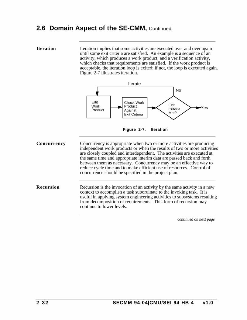
2 -32 SECMM-94-04|CMU/SEI-94-HB-4 v1.0
2.6 Domain Aspect of the SE-CMM, Continued
Iteration Iteration implies that some activities are executed over and over againuntil some exit criteria are satisfied. An example is a sequence of anactivity, which produces a work product, and a verification activity,which checks that requirements are satisfied. If the work product isacceptable, the iteration loop is exited; if not, the loop is executed again.Figure 2-7 illustrates iteration.
YesEdit Work Product
Check Work Product AgainstExit Criteria
Exit Criteria Met?
Iterate
No
Figure 2-7. Iteration
Concurrency Concurrency is appropriate when two or more activities are producingindependent work products or when the results of two or more activitiesare closely coupled and interdependent. The activities are executed atthe same time and appropriate interim data are passed back and forthbetween them as necessary. Concurrency may be an effective way toreduce cycle time and to make efficient use of resources. Control ofconcurrence should be specified in the project plan.
Recursion Recursion is the invocation of an activity by the same activity in a newcontext to accomplish a task subordinate to the invoking task. It isuseful in applying system engineering activities to subsystems resultingfrom decomposition of requirements. This form of recursion maycontinue to lower levels.
continued on next page

SECMM-94-04|CMU/SEI-94-HB-4 v1.0 2 -33
2.6 Domain Aspect of the SE-CMM, Continued
Control andsequencingexample
Figures 2-8 and 2-9 show a more complete example process whichcontains instances of iteration, concurrency, and recursion. In Figure 2-8 the context of a defined process for developing a system is shown.The activity called Develop System is exploded into greater detail inFigure 2-9.
Iteration is demonstrated in loops involving making a work product,checking or verifying the product and reporting exceptions back to themaking activity for correction. One example of this iteration is in theloop Derive Requirements -> Verify Requirements -> DeriveRequirements. Another is the overall loop Develop System -> ValidateSystem -> Develop System.
Concurrency is demonstrated in the activities of Derive and AllocateRequirements and the activities of Develop Physical Architecture andCheck Feasibility. Notice also that these concurrent activities exchangeinformation as they proceed. Derived Requirements are furnished toDevelop Physical Architecture to guide the analysis of candidatesolutions. A Structure flows from Develop Physical Architecture toAllocate Requirements to use in the allocation process. Exceptionsnoted in the Check Feasibility activity are furnished to both DeriveRequirements and Develop Physical Architecture so that necessarychanges in their work products can be made.
Recursion is shown when the activity Develop System is called upon todevelop each of the several subsystems described in the PhysicalArchitecture and the Allocated Requirements. These instances ofDevelop System can proceed concurrently until they have produced thesubsystems for the system. At that point, the concurrent tasks arejoined together by Integrate System.
The output of Develop System is an integrated system ready for ValidateSystem.
continued on next page
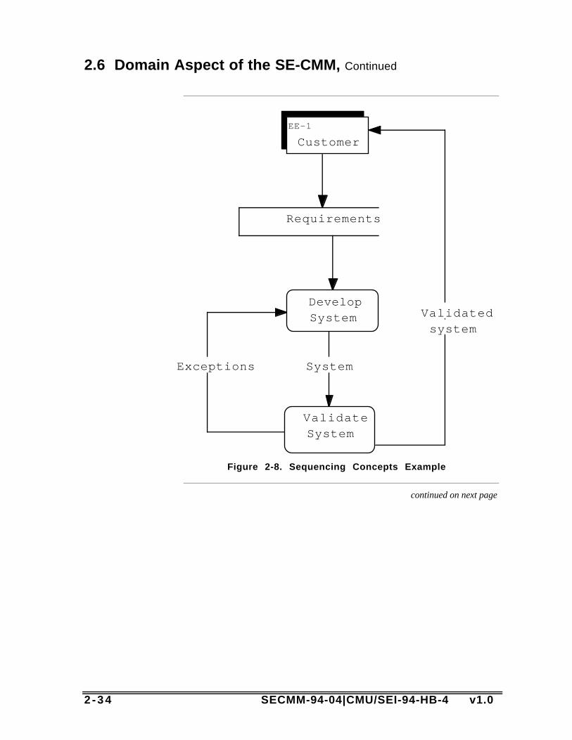
2 -34 SECMM-94-04|CMU/SEI-94-HB-4 v1.0
2.6 Domain Aspect of the SE-CMM, Continued
EE-1
Customer
DevelopSystem
ValidateSystem
Requirements
Exceptions System
Validatedsystem
Figure 2-8. Sequencing Concepts Example
continued on next page
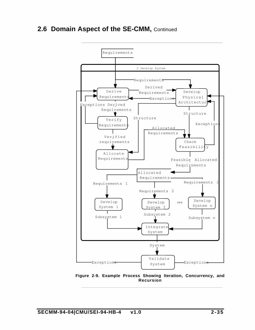
SECMM-94-04|CMU/SEI-94-HB-4 v1.0 2 -35
2.6 Domain Aspect of the SE-CMM, Continued
2 Develop System
Requirements
Validate
System
Derive
RequirementsDevelop
PhysicalArchitecture
Verify
Requirements
AllocateRequirements
CheckFeasibility
DevelopSystem 1
DevelopSystem 2
DevelopSystem n
IntegrateSystem
AllocatedRequirements
System
Requirements
DerivedRequirements
Exceptions
Derived
Requirements
Verifiedrequirements
StructureStructure
Feasible Allocated
Requirements
Subsystem nSubsystem 2
Subsystem 1
Requirements 1
Requirements 2
Requirements 3
Exceptions Exceptions
ExceptionsAllocated
Requirements
Exceptions
¥¥¥
Figure 2-9. Example Process Showing Iteration, Concurrency, andRecursion

2 -36 SECMM-94-04|CMU/SEI-94-HB-4 v1.0
SECMM-94-04|CMU/SEI-94-HB-4 v1.0 3 - 1
Chapter 3: Using the SE-CMM
Introduction This chapter provides discussion on using the SE-CMM fororganizational process improvement and design.
In thischapter
Topic See Page3.1 Many Usage Contexts 3-2
3.2 Using the SE-CMM to Support Appraisal 3-4
3.3 Using the SE-CMM to Support ProcessImprovement
3-7
3.4 Using the SE-CMM in Process Design 3-12
3 - 2 SECMM-94-04|CMU/SEI-94-HB-4 v1.0
3.1 Many Usage Contexts
Product/projectcontext
Practitioners in systems engineering recognize that there are as manyproduct contexts as there are products in the marketplace, and themethods used to accomplish product development are as varied as theproducts themselves. However, there are some issues related to productand project context that are known to have an impact on the wayproducts are conceived, produced, delivered, and maintained. Twoissues in particular have significance for the SE-CMM:
• type of customer base (negotiated vs. market driven), and• production cycle (small run, high value vs. large run, lower value).
The differences between two diverse customer bases and the impacts ofthose differences in the SE-CMM, are discussed below. This isprovided as an example of how an organization or industry segmentmight go about analyzing appropriate use of the SE-CMM in theirenvironment.
SE-CMMnot limitedto aparticularindustrysegment
Every industry reflects its own particular culture, nomenclature, andcommunication style. By minimizing the role dependencies andorganization structure implications, the authors hope that practitionersfrom all industry segments will be able to easily translate the conceptsexpressed in the SE-CMM into their own language and culture.However, because of the makeup of the author team, it is natural that thelanguage used to convey SE-CMM concepts has some flavor of theaerospace contractor industry, in which many of the authors have spentsignificant portions of their careers. Users are urged to look beyondspecific terminology differences to the common concepts underneath theterminology. Users are also encouraged to communicate problemsusing the SE-CMM to the project, via the issue form attached to thisdocument.
continued on next page

SECMM-94-04|CMU/SEI-94-HB-4 v1.0 3 - 3
3.1 Many Usage Contexts, Continued
Type ofcustomerbase
The SE-CMM can be applied in both single-customer and multi-customer segments. The table below illustrates some differences thatare evident in single vs. multi-customer segments that relate to the SE-CMM. Because of these differences, SE-CMM users may find it usefulto tailor the terminology in the model to reflect their customer segment.
Aspect CharacteristicsSeen with
Sing leCustomer
CharacteristicsSeen withMultiple
Customers
SE-CMMImplications
Number ofcustomers
One entity, eitherone individual orone organization.
Many entities, eithermany individuals whocan be segmentedaccording to specificcharacteristics, ormany organizations.
Language related tocustomer, customersurrogates shouldbe emphasized.
Visibility ofthe customer
Customer is highlyvisible to thedeveloper.
Customer is not oftendirectly visible to thedeveloper: surrogates,such as focus groupsor marketingdepartments, providethe interface to thedeveloper.
UnderstandCustomer Needsprocess area (PA)must be interpretedto suit the context.
Methods ofmeasuringcustomersatisfaction
• Award of followon work
• Periodic reviews
• Award fee
• Incentive fee
• Customerfeedback
• Marketplace buyingpatterns
• Creation of follow-on customerdemands
• Customer survey
Manage ProductLine Evolution PAand otherorganizational PAsmay be affected byhow supportfunctions areviewed in relationto customer-focused activities.
Table 3-1. Customer Base

3 - 4 SECMM-94-04|CMU/SEI-94-HB-4 v1.0
3.2 Using the SE-CMM to Support Appraisal
Introduction The SE-CMM is structured to support a wide variety of improvementactivities, including self-administered appraisals or internal appraisalsaugmented by expert "facilitators" from inside or outside theorganization. Although it is primarily intended for internal processimprovement, it can also be used to evaluate a potential vendor'scapability to perform its systems engineering process. (This use is notrecommended by the SE-CMM Project at this time.)
The SE-CMMAppraisalMethod
Although it is not required that any particular appraisal method be usedwith the SE-CMM, an appraisal method designed to maximize the utilityof the model has been designed by the SE-CMM Project. The SE-CMMAppraisal Method (SAM) will be fully described, along with somesupport materials for conducting appraisals, in SECMM-94-06|CMU/SEI-94-HB-05, SE-CMM Appraisal Method Description.(This document will be published early in 1995 by the project viaCarnegie Mellon University’s Software Engineering Institute,Pittsburgh, PA.) The basic premises of the appraisal method are listedhere to provide a context for the reader as to how the model might beused in an appraisal.
Features ofthe SAM
SAM is an organizational or project-level appraisal method that usesmultiple data gathering methods to obtain information on the processesbeing practiced within the organization or project selected for appraisal.The purposes of a SAM-style appraisal in its first release version aretwofold:
• obtain a baseline or benchmark of actual practice related to systemsengineering within the organization or project, and
• create and support momentum for improvement within multiple levelsof the organizational structure.
SAM is a method which is tailorable to meet the organization's orproject's need, and some guidance on tailoring will be provided in theSAM description document.
Data gathering is primarily via questionnaires that directly reflect thecontents of the model, and a series of both structured and unstructuredinterviews with key personnel involved in the performance of theorganization's processes. Some of these individuals would beconsidered systems engineers, others would be in other roles (e.g.,configuration managers) that support systems engineering tasks.
continued on next page

SECMM-94-04|CMU/SEI-94-HB-4 v1.0 3 - 5
3.2 Using the SE-CMM to Support Appraisal, Continued
Features ofthe SAM,continued
Multiple feedback sessions are conducted with the appraisal participants,culminating in a briefing to all participants plus the sponsor of theappraisal. Capability levels are assigned to each of the process areasthat were appraised. The briefing also includes a set of prioritizedstrengths and weaknesses that support process improvement based onthe organization's stated appraisal goals.
Determiningcapability toperformsystemsengineeringprocesses
Figure 3-1 illustrates how the process areas (base practices) and thecommon features (generic practices) can be used to determine theprocess capability of systems engineering processes. A capability levelof 0 to 5 can be determined for each process area.
Process Area 1
Process Area 2
1 2 3 4
Process Capability Level
Process Area n
Process Areas 5
Are basepractices includedin performance ofthe process?
How well are the base practices/process areas managed and theirprocesses institutionalized?
Figure 3-1. Determining Process Capability
Using bothsides of thearchitecturein appraisal
The first step in developing a profile of an organization's capability toperform its systems engineering process is to determine whether thebasic systems engineering process (all the base practices) isimplemented within the organization (not just written down) via theirperformed process. The second step is to assess how well thecharacteristics (base practices) of the process that have beenimplemented are managed and institutionalized by looking at the basepractices in the context of the generic practices. Consideration of boththe base practices and generic practices in this way results in a processcapability profile that can help the organization to determine theimprovement activities that will be of most benefit in the context of itsbusiness goals.
continued on next page
3 - 6 SECMM-94-04|CMU/SEI-94-HB-4 v1.0
3.2 Using the SE-CMM to Support Appraisal, Continued
Relationshipbetweengeneric andbasepractices
Because process capability levels are primarily determined by applyingthe generic practices to the base practices, the SE-CMM may appear tocontain a certain amount of redundancy between the generic practicesand base practices. This is most visible when looking at some of theproject and organizational process areas.
Example ofrelationshipbetweengeneric/basepractices
The SE-CMM contains both base practices and a generic practice thataddress configuration management: the Manage Configurations processarea and generic practice 2.2.2 (“Place work products of the processarea under version control or configuration management, asappropriate”). However, the focus of Manage Configurations is theprocess being used for managing configurations and the generic practiceis determining whether or not the project's process for configurationmanagement is resulting in action related to the process area underinvestigation, e.g., in relation to Derive and Allocate Requirements.
In general, the base practices in cases such as this should be viewed asguidance on the basic aspects of the topics that need to be addressed,and the related generic practices deal with deployment of the basepractices to the project. Keep in mind that the application of the genericpractices to each process area results in a unique interpretation of thegeneric practice for the subject process area. Base practices, on theother hand, generally maintain their interpretation over the scope of themodel.
Sequencing The practices of many of the process areas would be expected to be seena number of times in the execution of an organization's process for theproduct life cycle. The process areas should be considered a source forpractices whenever there is a need to incorporate the associated purposein a project's or organization's process. In an appraisal, always keep inmind that the SE-CMM does not imply a sequence: sequencing shouldbe determined based on the organization's or project's selected life cycleand other business parameters (see Section 3.4, Using the SE-CMM inProcess Design).
SECMM-94-04|CMU/SEI-94-HB-4 v1.0 3 - 7
3.3 Using the SE-CMM to Support Process Improvement
Introduction Either with or without an appraisal to benchmark an organization’ssystems engineering practices, there are several aspects of the SE-CMMthat should be considered when using it as the basis to design animprovement program. This section does not provide overall guidanceon initiating and conducting an improvement program. There are manysources within industry for approaches to organizational improvement,and most should be able to be used with the SE-CMM or adapted forSE-CMM use.
Prioritizingimprovementbased onbusinessgoals
It should be emphasized that any process improvement effort, using anyreference model, should be constructed to support the business goals ofthe organization. An organization using the SE-CMM should prioritizethe process areas relative to their business goals and strive forimprovement in the highest priority process areas first.
Tailoring The model defines only those elements that are considered by theauthors to be essential for the practice of good systems engineering. Assuch the model is not intended, in general, to be tailored. However, notall projects may need to use processes that exhibit all the characteristicsassociated with each process area. Under such circumstances, theproject should follow a process to tailor out the process activity relatedto the unnecessary process area from the organization's systemsengineering process for that specific project or the organization, asappropriate. Tailoring should, in all cases, be based on theorganization's business goals and customer needs.
Gainingleveragefrom otherexperiences
Empirical data are not readily available on the benefits of processimprovement to systems engineering. However, because systemsengineering has a strong influence on the success of other disciplines,the benefits from improving the systems engineering process areprojected to equal or exceed the benefits of process improvement inother disciplines such as software engineering.
continued on next page

3 - 8 SECMM-94-04|CMU/SEI-94-HB-4 v1.0
3.3 Using the SE-CMM to Support Process Improvement, Continued
Gainingleveragefrom otherexperiences,continued
In the case of software process improvement, organizations that havedone software process improvements for more than 3 years have gainedsubstantial benefits [Herbsleb 94]:
• Return on investment of 7:1.• 37% average gain per year in productivity.• 18% increase per year in the proportion of defects found in pre-test.• 19% reduction in time to market.• 45% reduction in filed error reports per year.
This is comparable to published total quality management reports fromother industries. Surveys and case studies on software processimprovement are listed below to support model users who need tounderstand the potential analogies between software and systemsengineering process improvement.
continued on next page

SECMM-94-04|CMU/SEI-94-HB-4 v1.0 3 - 9
3.3 Using the SE-CMM to Support Process Improvement, Continued
List ofsoftwareprocessimprove-mentreferences
Joe Besselman and Stan Rifkin, “The Effect of Software ProcessImprovement on the Economics of Procurement,” Proceedings of the6th SEPG National Meeting, Dallas, TX, 25-28 April 1994.
C. Billings, J. Clifton, B. Kolkhorst, E. Lee, and W.B. Wingert,“Journey to a Mature Software Process,” IBM Systems Journal, Vol.33, No. 1, 1994, pp. 46-61.
Raymond Dion, “Process Improvement and the Corporate BalanceSheet,” IEEE Software, Vol. 10, No. 4, July 1993, pp. 28-35.
James Herbsleb, Anita Carleton, et al., Benefits of CMM-BasedSoftware Process Improvement: Initial Results (CMU/SEI-94-TR-13).Pittsburgh, PA: Software Engineering Institute, Carnegie MellonUniversity, August 1994.
Watts S. Humphrey, Terry R. Snyder, and Ronald R. Willis, “SoftwareProcess Improvement at Hughes Aircraft,” IEEE Software, Vol. 8, No.4, July 1991, pp. 11-23.
A. Johnson, “Software Process Improvement Experience in the DP/MISFunction,” Proceedings of the 16th International Conference onSoftware Engineering, IEEE Computer Society Press, Sorrento, Italy,16-21 May 1994, pp. 323-330.
Jed Johnson, “How We Climbed to Maturity Level Two,” ApplicationDevelopment Trends, April 1994, pp. 20-23.
W.H. Lipke and K.L. Butler, “Software Process Improvement: ASuccess Story,” Crosstalk: The Journal of Defense SoftwareEngineering, No. 38, November 1992, pp. 29-31.
R. A. Radice, J. T. Harding, P. E. Munnis, and R. W. Phillips, “AProgramming Process Study,” IBM Systems Journal, vol. 24, no. 2,1985.
H. Wohlwend and S. Rosenbaum, “Software Improvements in anInternational Company,” Proceedings of the 15th InternationalConference on Software Engineering, IEEE Computer Society Press,May 1993.
continued on next page
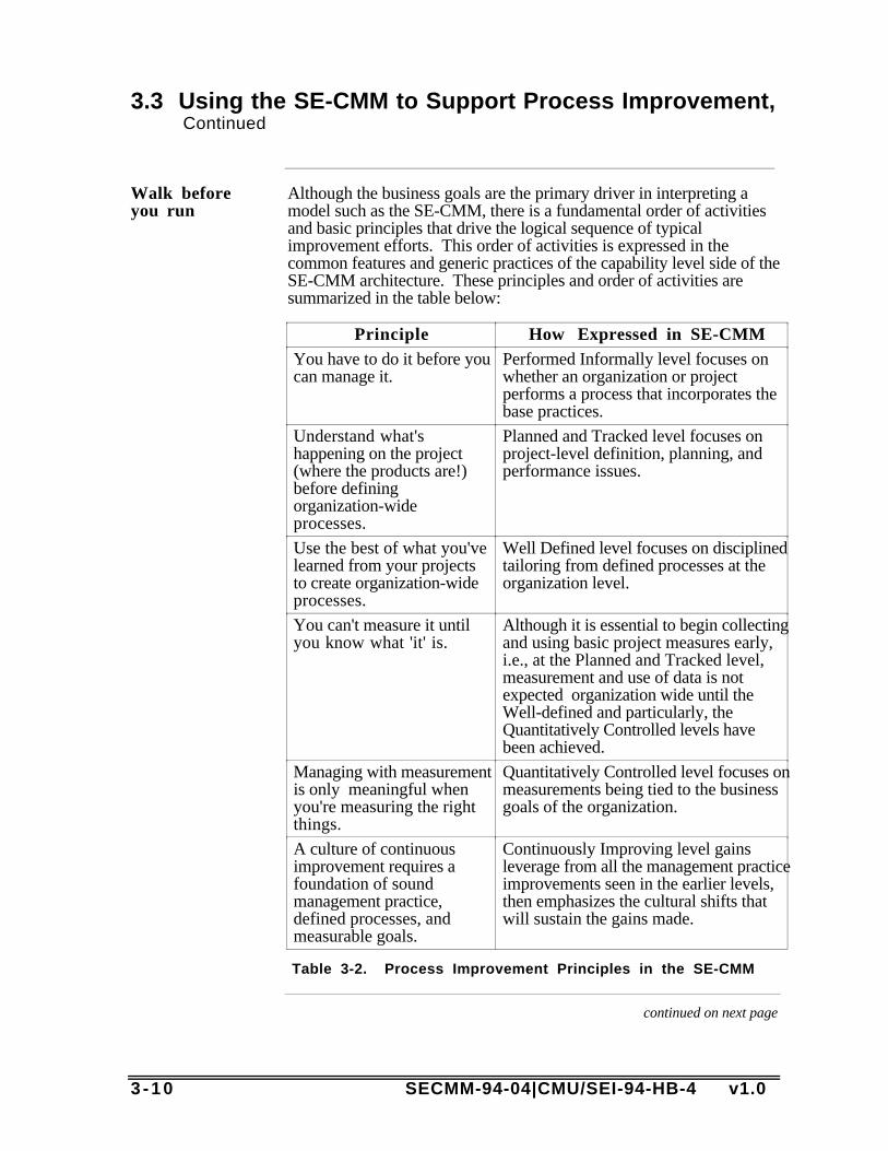
3 -10 SECMM-94-04|CMU/SEI-94-HB-4 v1.0
3.3 Using the SE-CMM to Support Process Improvement, Continued
Walk beforeyou run
Although the business goals are the primary driver in interpreting amodel such as the SE-CMM, there is a fundamental order of activitiesand basic principles that drive the logical sequence of typicalimprovement efforts. This order of activities is expressed in thecommon features and generic practices of the capability level side of theSE-CMM architecture. These principles and order of activities aresummarized in the table below:
Principle How Expressed in SE-CMMYou have to do it before youcan manage it.
Performed Informally level focuses onwhether an organization or projectperforms a process that incorporates thebase practices.
Understand what'shappening on the project(where the products are!)before definingorganization-wideprocesses.
Planned and Tracked level focuses onproject-level definition, planning, andperformance issues.
Use the best of what you'velearned from your projectsto create organization-wideprocesses.
Well Defined level focuses on disciplinedtailoring from defined processes at theorganization level.
You can't measure it untilyou know what 'it' is.
Although it is essential to begin collectingand using basic project measures early,i.e., at the Planned and Tracked level,measurement and use of data is notexpected organization wide until theWell-defined and particularly, theQuantitatively Controlled levels havebeen achieved.
Managing with measurementis only meaningful whenyou're measuring the rightthings.
Quantitatively Controlled level focuses onmeasurements being tied to the businessgoals of the organization.
A culture of continuousimprovement requires afoundation of soundmanagement practice,defined processes, andmeasurable goals.
Continuously Improving level gainsleverage from all the management practiceimprovements seen in the earlier levels,then emphasizes the cultural shifts thatwill sustain the gains made.
Table 3-2. Process Improvement Principles in the SE-CMM
continued on next page
SECMM-94-04|CMU/SEI-94-HB-4 v1.0 3 -11
3.3 Using the SE-CMM to Support Process Improvement, Continued
Someexpectedresults
Based on analogies in the software and other communities, some resultsthat provide leverage to the organization in terms of process and productimprovement can be predicted. These are discussed in the blocksbelow.
Improvingpredictability
The first improvement expected as an organization matures ispredictability. As capability increases, the difference between targetedresults and actual results decreases across projects. For instance, level 1organizations often miss their originally scheduled delivery dates by awide margin, whereas organizations at a higher capability level shouldbe able to predict the outcome of cost and schedule aspects of a projectwith increased accuracy.
Improvingcontrol
The second improvement expected as an organization matures is control.As process capability increases, incremental results can be used toestablish revised targets more accurately. Alternative corrective actionscan be evaluated based on experience with the process and otherprojects' process results in order to select the best application of controlmeasures. As a result, organizations with a higher capability level willbe more effective in controlling performance within an acceptable range.
Improvingeffectiveness
The third improvement expected as an organization matures iseffectiveness. Targeted results improve as the maturity of theorganization increases. That is, as an organization matures, costsdecrease, development time becomes shorter, and productivity andquality increase. In a level 1 organization, development time can bequite long because of the amount of rework that must be performed tocorrect mistakes. In contrast, higher maturity level organizations haveincreased process effectiveness and have reduced costly rework,allowing overall development time to be shortened.

3 -12 SECMM-94-04|CMU/SEI-94-HB-4 v1.0
3.4 Using the SE-CMM in Process Design
Introduction This section provides brief guidance on issues related to using the SE-CMM to support process design. There are many sources for designingprocesses which can be referenced to support an organization's processdesign needs. This section sets a context for how the SE-CMM couldbe used in a design activity.
Analyzingyourorganiza-tionalcontext
The first step in designing processes that will meet the business needs ofan enterprise is to understand the business, product, and organizationalcontext that will be present when the process is being implemented.There are many aspects of process design that are not addressed by theSE-CMM, since they are context specific. Nevertheless, these issuesmust be addressed when designing or improving processes for yourorganization. Some questions that need to be answered before the SE-CMM can be used for process design include
• What life cycle will be used as a framework for this process?• How is the organization structured to support projects?• How are support functions handled (e.g., by the project or the
organization)?• What are the management and practitioner roles used in this
organization?• How critical are these processes to organizational success?
Understanding the cultural and business contexts in which the SE-CMMwill be used is a key to its successful application in process design.
continued on next page
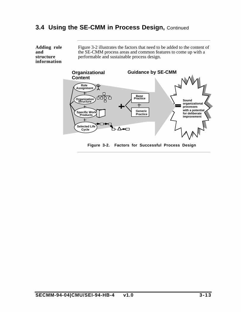
SECMM-94-04|CMU/SEI-94-HB-4 v1.0 3 -13
3.4 Using the SE-CMM in Process Design, Continued
Adding roleandstructureinformation
Figure 3-2 illustrates the factors that need to be added to the content ofthe SE-CMM process areas and common features to come up with aperformable and sustainable process design.
Role Assignment
Organization Structure
Specific Work Products
Selected LifeCycle
Guidance by SE-CMMOrganizational Content
Soundorganizationalprocesses with a potential for deliberate improvement
Base Practice
GenericPractice
Figure 3-2. Factors for Successful Process Design

3 -14 SECMM-94-04|CMU/SEI-94-HB-4 v1.0

SECMM-94-04|CMU/SEI-94-HB-4 v1.0 4 - 1
Chapter 4: The SE-CMM Generic & BasePractices
Introduction This chapter contains the practices for both the process capability anddomain aspects of the SE-CMM. Section 4A contains the genericpractices (process capability aspect), organized by common feature andcapability level. Section 4B contains the base practices (domain aspect),organized by process area. The process areas are sequencedalphabetically within each process category.
4 - 2 SECMM-94-04|CMU/SEI-94-HB-4 v1.0
Chapter 4A: Generic Practices
Introduction This chapter contains the generic practices, that is, the practices adaptedfrom the ISO SPICE Baseline Practices Guide that are generic and applyto all processes. The generic practices (GPs) are used in a processappraisal to determine the capability of any process. The genericpractices are grouped according to common feature and capability level.
“Process”vs. “processarea”
The BPG uses the term "process" where the SE-CMM uses "processarea."
Source This chapter is reproduced with minor adaptations for the SE-CMMfrom the ISO (SPICE) Baseline Practices Guide v1.00a, with thepermission of the BPG technical center manager. The BPG is a work inprogress; therefore, the BPG development team would appreciate yourcomments on the generic practices in order to improve both the BPGand the SE-CMM. Comments on the generic practices may be made tothe SE-CMM Project or directly to the BPG technical center manager,Michael D. Konrad, SEI, 4500 Fifth Ave., Pittsburgh, PA 15237;email: [email protected].
In thischapter
Chapter 4A is divided into the six process capability levels shownbelow:
Topic See PageThe Not Performed level 4-3
The Performed Informally level 4-4
The Planned and Tracked level 4-5
The Well Defined level 4-10
The Quantitatively Controlled level 4-13
The Continuously Improving level 4-14
Adaptationstothe BPG
The "Notes" sections of the BPG generic practices were updated toreflect SE-CMM cross-references. In addition, cross-referencesbetween generic practices and between generic practices and processareas of the SE-CMM were added.

SECMM-94-04|CMU/SEI-94-HB-4 v1.0 4 - 3
Capability Level 0 - Not Performed
Description The Not Performed level has no common features. There is generalfailure to perform the base practices in the process area. Where there arework products that result from performing the process, they are noteasily identifiable or accessible.

4 - 4 SECMM-94-04|CMU/SEI-94-HB-4 v1.0
Capability Level 1 - Performed Informally
Description Base practices of the process area are generally performed. Theperformance of these base practices may not be rigorously planned andtracked. Performance depends on individual knowledge and effort.Work products of the process area testify to their performance.Individuals within the organization recognize that an action should beperformed, and there is general agreement that this action is performedas and when required. There are identifiable work products for theprocess.
CommonFeature 1.1:BasePractices arePerformed
1.1.1 Perform the process. Perform a process that implements thebase practices of the process area to provide work products and/orservices to a customer.
Note: This process may be termed the “informal process.” Thecustomer(s) of the process area may be internal or external to theorganization.

SECMM-94-04|CMU/SEI-94-HB-4 v1.0 4 - 5
Capability Level 2 - Planned and Tracked
Description Performance of the base practices in the process area is planned andtracked. Performance according to specified procedures is verified.Work products conform to specified standards and requirements.Measurement is used to track process area performance, thus enablingthe organization to manage its activities based on actual performance.The primary distinction from the Performed Informally level is that theperformance of the process is planned and managed.
CommonFeature 2.1:PlanningPerformance
2.1.1 Allocate resources. Allocate adequate resources (includingpeople) for performing the process area.
Relationship to process areas: Identification of critical resources is donein process area PA 12 - Plan Technical Effort.
2.1.2 Assign responsibilities. Assign responsibilities fordeveloping the work products and/or providing the services of theprocess area.
Relationship to process areas: This practice is particularly related toprocess area PA 12 - Plan Technical Effort.
continued on next page

4 - 6 SECMM-94-04|CMU/SEI-94-HB-4 v1.0
Capability Level 2 - Planned and Tracked, Continued
CommonFeature 2.1:PlanningPerformance,continued
2.1.3 Document the process. Document the approach toperforming the process area in standards and/or procedures.
Note: Participation of the people who perform a process (its owners) isessential to creating a usable process description. Processes in anorganization or on a project need not correspond one to one with theprocess areas in the SE-CMM. Therefore, a process covering a processarea may be described in more than one way (e.g., policies, standards,and/or procedures), to cover a process area, and a process descriptionmay span more than one process area.
Relationship to other generic practices: This is the “level 2” processdescription. The process descriptions evolve with increasing processcapability (see 3.1.1, 3.1.2, 5.2.3, 5.2.4 for descriptions of thisprocess).
Standards and procedures that describe the process at this level are likelyto include measurements, so that the performance can be tracked withmeasurement (see common feature 2.4).
Relationship to process areas: This practice is related to process areasPA 13 - Define Organization’s Systems Engineering Process and PA 14- Improve Organization’s Systems Engineering Processes.
2.1.4 Provide tools. Provide appropriate tools to supportperformance of the process area.
Relationship to other generic practices: Tool changes may be part ofprocess improvements (see 5.2.3, 5.2.4 for practices on processimprovements).
Relationship to process areas: Tools are managed in PA 16 - ManageSystems Engineering Support Environment.
2.1.5 Ensure training. Ensure that the individuals performing theprocess area are appropriately trained in how to perform the process.
Note: Training, and how it is delivered, will change with processcapability due to changes in how the process(es) is performed andmanaged.
Relationship to process areas: Training and training management isdescribed in PA 17 - Manage Systems Engineering Training.
continued on next page
SECMM-94-04|CMU/SEI-94-HB-4 v1.0 4 - 7
Capability Level 2 - Planned and Tracked, Continued
CommonFeature 2.1:PlanningPerformance,continued
2.1.6 Plan the process. Plan the performance of the process area.
Note: Plans for process areas in the engineering and project categoriesmay be in the form of a project plan, whereas plans for the organizationcategory may be at the organizational level.
Relationship to process areas: Project planning is described in processarea PA 12 - Plan Technical Effort.
CommonFeature 2.2:DisciplinedPerformance
2.2.1 Use plans, standards, and procedures. Use documentedplans, standards, and/or procedures in implementing the process area.
Note: A process performed according to its process descriptions istermed a “described process.” Process measures should be defined inthe standards, procedures, and plans.
Relationship to other generic practices: The standards and proceduresused were documented in 2.1.3, and the plans used were documented in2.1.6. This practice is an evolution of 1.1.1 and evolves to 3.2.1.
2.2.2 Do configuration management. Place work products of theprocess area under version control or configuration management, asappropriate.
Note: Where process area PA 09 - Manage Configurations focuses onthe general practices of configuration management, this generic practiceis focused on the deployment of these practices in relation to the workproducts of the individual process area under investigation.
Relationship to process areas: The typical practices needed to supportsystems engineering in the configuration management discipline aredescribed in process area PA 09 - Manage Configurations.
continued on next page
4 - 8 SECMM-94-04|CMU/SEI-94-HB-4 v1.0
Capability Level 2 - Planned and Tracked, Continued
CommonFeature 2.3:VerifyingPerformance
2.3.1 Verify process compliance. Verify compliance of theprocess with applicable standards and/or procedures.
Relationship to other generic practices: The applicable standards andprocedures were documented in 2.1.3 and used in 2.2.1.
Relationship to process areas: The quality management and/orassurance process is described in process area PA 08 - Ensure Quality.
2.3.2 Audit work products. Verify compliance of work productswith the applicable standards and/or requirements.
Relationship to other generic practices: The applicable standards andprocedures were documented in 2.1.3 and used in 2.2.1.
Relationship to process areas: Product requirements are developed andmanaged in process area PA 02 - Develop Functional and PerformanceRequirements. Verification and validation is further addressed in PA 07- Verify and Validate System.
CommonFeature 2.4:TrackingPerformance
2.4.1 Track with measurement. Track the status of the processarea against the plan using measurement.
Note: Building a history of measures is a foundation for managing bydata, and is begun here.
Relationship to other generic practices: The use of measurement impliesthat the measures have been defined and selected in 2.1.3 and 2.1.6,and data have been collected in 2.2.1.
Relationship to process areas: Project tracking is described in processarea PA 11 - Monitor and Control Technical Effort.
continued on next page
SECMM-94-04|CMU/SEI-94-HB-4 v1.0 4 - 9
Capability Level 2 - Planned and Tracked, Continued
CommonFeature 2.4:TrackingPerformance,continued
2.4.2 Tracking Performance. Take corrective action asappropriate when progress varies significantly from that planned.
Note: Progress may vary because estimates were inaccurate,performance was affected by external factors, or the requirements, onwhich the plan was based, have changed. Corrective action mayinvolve changing the process(es), changing the plan, or both.
Relationship to process areas: Project control is described in processarea PA 11 - Monitor and Control Technical Effort.

4 -10 SECMM-94-04|CMU/SEI-94-HB-4 v1.0
Capability Level 3 - Well Defined
Description Base practices are performed according to a well-defined process usingapproved, tailored versions of standard, documented processes. Theprimary distinction from the Planned and Tracked level is that theprocess is planned and managed using an organization-wide standardprocess.
CommonFeature 3.1:Defining aStandardProcess
3.1.1 Standardize the process. Document a standard process orfamily of processes for the organization, that describes how toimplement the base practices of the process area.
Note: The critical distinction between generic practices 2.1.3 and 3.1.1,the level 2 and level 3 process descriptions, is the scope of applicationof the policies, standards, and procedures. In 2.1.3, the standards andprocedures may be in use in only a specific instance of the process,e.g., on a particular project. In 3.1.1, policies, standards, andprocedures are being established at an organizational level for commonuse, and are termed the “standard process definition.”
More than one standard process description may be defined to cover aprocess area, as the processes in an organization need not correspondone to one with the process areas in this capability maturity model.Also, a defined process may span multiple process areas. The SE-CMM does not dictate the organization or structure of processdescriptions. Therefore, more than one standard process may bedefined to address the differences among application domains, customerconstraints, etc. These are termed a “standard process family.”
Relationship to other generic practices: The “level 2” processdescription was documented in 2.1.3. The “level 3” process descriptionis tailored in 3.1.2.
Relationship to process areas: The process for developing a processdescription is described in process area PA 13 - Define Organization’sSystems Engineering Process.
continued on next page

SECMM-94-04|CMU/SEI-94-HB-4 v1.0 4 -11
Capability Level 3 - Well Defined, Continued
CommonFeature 3.1,continued
3.1.2 Tailor the standard process. Tailor the organization'sstandard process family to create a defined process that addresses theparticular needs of a specific use.
Note: Tailoring the organization’s standard process creates the “level 3”process definition. For defined processes at the project level, thetailoring addresses the particular needs of the project.
Relationship to other generic practices: The organization's standardprocess (family) is documented in 3.1.1. The tailored process definitionis used in 3.2.1.
Relationship to process areas: Tailoring guidelines are defined inprocess area PA 13 - Define Organization’s Systems EngineeringProcess.
CommonFeature 3.2:Perform theDefinedProcess
3.2.1 Use a well-defined process. Use a well-defined process inimplementing the process area.
Note: A “defined process” will typically be tailored from theorganization’s standard process definition. A well-defined process isone with policies, standards, inputs, entry criteria, activities,procedures, specified roles, measurements, validation, templates,outputs, and exit criteria that are documented, consistent, and complete.
Relationship to other generic practices: The organization’s standardprocess definition is described in 3.1.1. The defined process isestablished through tailoring in 3.1.2.
3.2.2 Perform defect reviews. Perform defect reviews ofappropriate work products of the process area.
Note: There is no process area for defect reviews, called “peer reviews”in ISO SPICE and the CMM for Software (in this regard, the SE-CMMdiffers from SPICE and the CMM for Software).
continued on next page
4 -12 SECMM-94-04|CMU/SEI-94-HB-4 v1.0
Capability Level 3 - Well Defined, Continued
CommonFeature 3.2,continued
3.2.3 Use well-defined data. Use data on performing the definedprocess to manage it.
Note: Measurement data that were first collected at level 2 are moreactively used by this point, laying the foundation for quantitativemanagement at the next level.
Relationship to other generic practices: This is an evolution of 2.4.2;corrective action taken here is based on a well-defined process, whichhas objective criteria for determining progress (see 3.2.1).
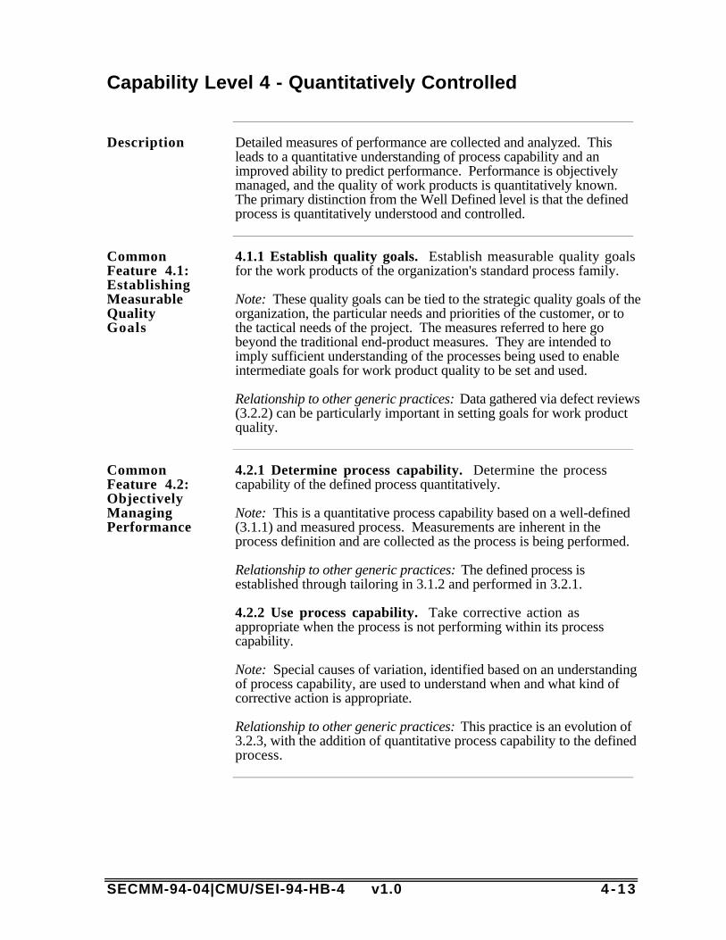
SECMM-94-04|CMU/SEI-94-HB-4 v1.0 4 -13
Capability Level 4 - Quantitatively Controlled
Description Detailed measures of performance are collected and analyzed. Thisleads to a quantitative understanding of process capability and animproved ability to predict performance. Performance is objectivelymanaged, and the quality of work products is quantitatively known.The primary distinction from the Well Defined level is that the definedprocess is quantitatively understood and controlled.
CommonFeature 4.1:EstablishingMeasurableQualityGoals
4.1.1 Establish quality goals. Establish measurable quality goalsfor the work products of the organization's standard process family.
Note: These quality goals can be tied to the strategic quality goals of theorganization, the particular needs and priorities of the customer, or tothe tactical needs of the project. The measures referred to here gobeyond the traditional end-product measures. They are intended toimply sufficient understanding of the processes being used to enableintermediate goals for work product quality to be set and used.
Relationship to other generic practices: Data gathered via defect reviews(3.2.2) can be particularly important in setting goals for work productquality.
CommonFeature 4.2:ObjectivelyManagingPerformance
4.2.1 Determine process capability. Determine the processcapability of the defined process quantitatively.
Note: This is a quantitative process capability based on a well-defined(3.1.1) and measured process. Measurements are inherent in theprocess definition and are collected as the process is being performed.
Relationship to other generic practices: The defined process isestablished through tailoring in 3.1.2 and performed in 3.2.1.
4.2.2 Use process capability. Take corrective action asappropriate when the process is not performing within its processcapability.
Note: Special causes of variation, identified based on an understandingof process capability, are used to understand when and what kind ofcorrective action is appropriate.
Relationship to other generic practices: This practice is an evolution of3.2.3, with the addition of quantitative process capability to the definedprocess.
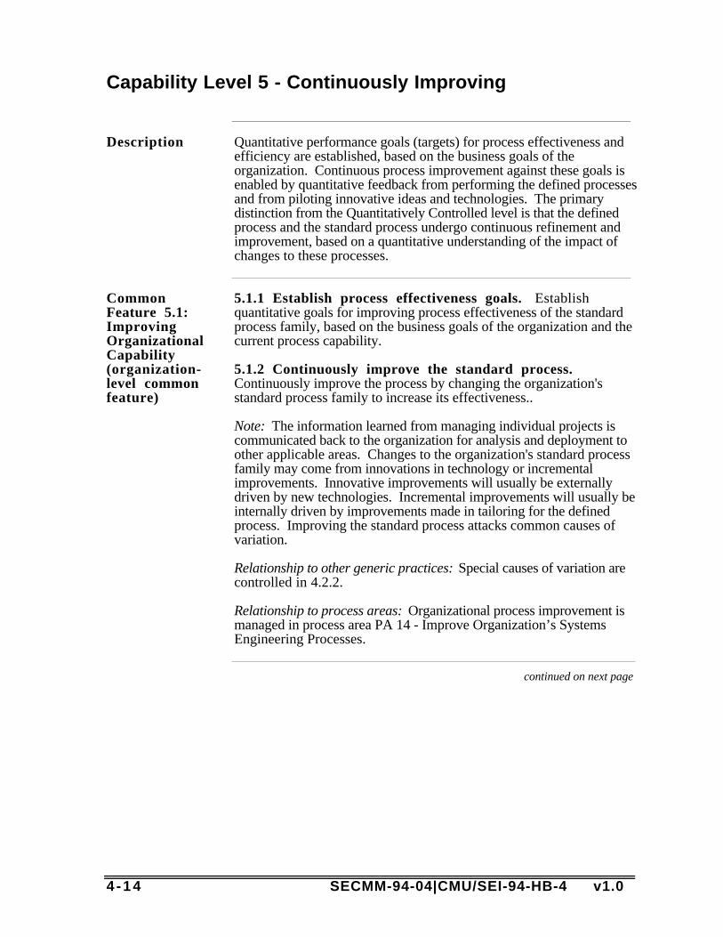
4 -14 SECMM-94-04|CMU/SEI-94-HB-4 v1.0
Capability Level 5 - Continuously Improving
Description Quantitative performance goals (targets) for process effectiveness andefficiency are established, based on the business goals of theorganization. Continuous process improvement against these goals isenabled by quantitative feedback from performing the defined processesand from piloting innovative ideas and technologies. The primarydistinction from the Quantitatively Controlled level is that the definedprocess and the standard process undergo continuous refinement andimprovement, based on a quantitative understanding of the impact ofchanges to these processes.
CommonFeature 5.1:ImprovingOrganizationalCapability(organization-level commonfeature)
5.1.1 Establish process effectiveness goals. Establishquantitative goals for improving process effectiveness of the standardprocess family, based on the business goals of the organization and thecurrent process capability.
5.1.2 Continuously improve the standard process.Continuously improve the process by changing the organization'sstandard process family to increase its effectiveness..
Note: The information learned from managing individual projects iscommunicated back to the organization for analysis and deployment toother applicable areas. Changes to the organization's standard processfamily may come from innovations in technology or incrementalimprovements. Innovative improvements will usually be externallydriven by new technologies. Incremental improvements will usually beinternally driven by improvements made in tailoring for the definedprocess. Improving the standard process attacks common causes ofvariation.
Relationship to other generic practices: Special causes of variation arecontrolled in 4.2.2.
Relationship to process areas: Organizational process improvement ismanaged in process area PA 14 - Improve Organization’s SystemsEngineering Processes.
continued on next page

SECMM-94-04|CMU/SEI-94-HB-4 v1.0 4 -15
Capability Level 5 - Continuously Improving, Continued
CommonFeature 5.2:ImprovingProcessEffectiveness
5.2.1 Perform causal analysis. Perform causal analysis ofdefects.
Note: Those who perform the process are typically participants in thisanalysis. This is a pro-active causal analysis activity as well as re-active. Defects from prior projects of similar attributes can be used totarget improvement areas for the new effort.
Relationship to other generic practices: Results of these analyses areused in 5.2.2, 5.2.3, and/or 5.2.4.
5.2.2 Eliminate defect causes. Eliminate the causes of defects inthe defined process selectively.
Note: Both common causes and special causes of variation are impliedin this generic practice, and each type of defect may result in differentaction.
Relationship to other generic practices: Causes were identified in 5.2.1.
5.2.3 Continuously improve the defined process.Continuously improve process performance by changing the definedprocess to increase its effectiveness.
Note: The improvements may be based on incremental improvements(5.2.2) or innovative improvements such as new technologies (perhapsas part of pilot testing). Improvements will typically be driven by thegoals established in 5.1.1.
Relationship to other generic practices: Practice 5.2.2 may be onesource of improvements. Goals were established in 5.1.1.
Relationship to process areas: Product technology insertion is managedin PA 15 - Manage Product Line Evolution.
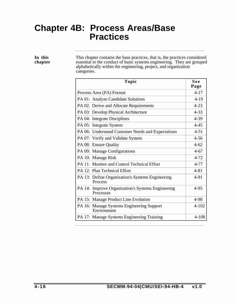
4 -16 SECMM-94-04|CMU/SEI-94-HB-4 v1.0
Chapter 4B: Process Areas/Base Practices
In thischapter
This chapter contains the base practices, that is, the practices consideredessential to the conduct of basic systems engineering. They are groupedalphabetically within the engineering, project, and organizationcategories.
Topic SeePage
Process Area (PA) Format 4-17
PA 01: Analyze Candidate Solutions 4-19
PA 02: Derive and Allocate Requirements 4-23
PA 03: Develop Physical Architecture 4-33
PA 04: Integrate Disciplines 4-39
PA 05: Integrate System 4-45
PA 06: Understand Customer Needs and Expectations 4-51
PA 07: Verify and Validate System 4-56
PA 08: Ensure Quality 4-62
PA 09: Manage Configurations 4-67
PA 10: Manage Risk 4-72
PA 11: Monitor and Control Technical Effort 4-77
PA 12: Plan Technical Effort 4-81
PA 13: Define Organization's Systems EngineeringProcess
4-91
PA 14: Improve Organization's Systems EngineeringProcesses
4-95
PA 15: Manage Product Line Evolution 4-98
PA 16: Manage Systems Engineering SupportEnvironment
4-102
PA 17: Manage Systems Engineering Training 4-108

SECMM-94-04|CMU/SEI-94-HB-4 v1.0 4 -17
Process Area Format
Currentcontents
At present, the SE-CMM domain aspect consists of 17 process areas(PAs), each of which contains a number of base practices. Eachprocess area is identified in the following subsections.
The general format of the process areas is shown in Figure 4-1. Thesummary description contains a brief overview of the purpose of thePA. Each PA is decomposed into a set of base practices (BPs). TheBPs are considered mandatory items, (i.e., they must be successfullyimplemented to accomplish the purpose of the process area theysupport). Each base practice is described in detail following the PAsummary.
Although the PAs are identified and discussed separately, they do notexist in a vacuum. Even the PAs in the engineering category (PA-01through PA-07), are inextricably intertwined with all the others in thecreation of good systems engineering processes, the implementation ofwhich produces sound, customer-pleasing products.
continued on next page

4 -18 SECMM-94-04|CMU/SEI-94-HB-4 v1.0
Process Area Format, Continued
Figure The following figure provides the general format of the process areasand describes the content of each part.
PA #: PA Title
SummaryDescription
The purpose of <PA Title> is. . .<description of the purpose of the PA and summary of its major points>
Process AreaNotes
<PA notes paragraphs>
Base PracticesList
The following list contains the titles of the base practices considered essential to thepractice of good systems engineering:
• BP #: BP Title.....
end of PA Summary Section
BP #BP Title
<BP text: imperative, verb-object statement that describes an essential element for attaining the purpose of the PA>
BP Description<BP description text: provides elaborations of the base practice text>
Typical Work Products<List of Work Products>
BP Notes<BP notes text: contains conceptual examples, potential techniques, methods, etc.; content of these will vary from base practice to base practice>
end of Process Area <PA Title>
Figure 4-1. Process Area Format
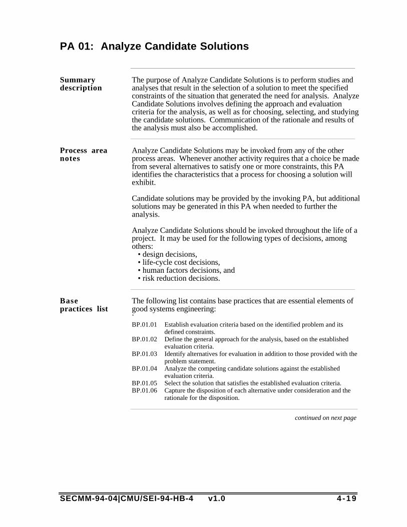
SECMM-94-04|CMU/SEI-94-HB-4 v1.0 4 -19
PA 01: Analyze Candidate Solutions
Summarydescription
The purpose of Analyze Candidate Solutions is to perform studies andanalyses that result in the selection of a solution to meet the specifiedconstraints of the situation that generated the need for analysis. AnalyzeCandidate Solutions involves defining the approach and evaluationcriteria for the analysis, as well as for choosing, selecting, and studyingthe candidate solutions. Communication of the rationale and results ofthe analysis must also be accomplished.
Process areanotes
Analyze Candidate Solutions may be invoked from any of the otherprocess areas. Whenever another activity requires that a choice be madefrom several alternatives to satisfy one or more constraints, this PAidentifies the characteristics that a process for choosing a solution willexhibit.
Candidate solutions may be provided by the invoking PA, but additionalsolutions may be generated in this PA when needed to further theanalysis.
Analyze Candidate Solutions should be invoked throughout the life of aproject. It may be used for the following types of decisions, amongothers:
• design decisions,• life-cycle cost decisions,• human factors decisions, and• risk reduction decisions.
Basepractices list
The following list contains base practices that are essential elements ofgood systems engineering: BP.01.01 Establish evaluation criteria based on the identified problem and its
defined constraints.BP.01.02 Define the general approach for the analysis, based on the established
evaluation criteria.BP.01.03 Identify alternatives for evaluation in addition to those provided with the
problem statement.BP.01.04 Analyze the competing candidate solutions against the established
evaluation criteria.BP.01.05 Select the solution that satisfies the established evaluation criteria.BP.01.06 Capture the disposition of each alternative under consideration and the
rationale for the disposition.
continued on next page

4 -20 SECMM-94-04|CMU/SEI-94-HB-4 v1.0
PA 01: Analyze Candidate Solutions, Continued
BP 01.01EstablishEvaluationCriteria
Establish evaluation criteria based on the identified problemand its defined constraints.
DescriptionThe criteria used in the evaluation process may vary considerably,depending on the stated problem and the level and complexity of theanalysis. The criteria are weighted or ranked in order of importance.For more complex analyses, there may be levels of criteria.
Typical Work Products• Captured evaluation criteria.• Trade study criteria.
NotesAt the system level, parameters of primary importance include systemperformance, cost effectiveness, logistics effectiveness, risk, andoperational availability.
BP 01.02DefineAnalysisApproach
Define the general approach for the analysis, based on theestablished evaluation criteria.
DescriptionThe general approach, resources, and procedures for performing theanalysis should be defined based on the evaluation criteria, personnel,tools, facilities, special equipment, and related resources. The generalapproach for the analysis should be defined and documented to ensurethat the procedures can be consistently repeated.
Typical Work Products• Trade study approach.
NotesSome example approaches that could be used to analyze candidatesolutions are
• prototyping,• simulation,• modeling,• trade study,• decision tree,• literature search,• exploitation of prior analyses, and• elicitation of expert judgment.
continued on next page

SECMM-94-04|CMU/SEI-94-HB-4 v1.0 4 -21
PA 01: Analyze Candidate Solutions, Continued
BP 01.03IdentifyAdditionalAlternatives
Identify alternatives for evaluation in addition to thoseprovided with the problem statement.
DescriptionCandidate solutions may be furnished with the need for analysis. As theanalysis proceeds, other alternatives may be added to the list ofcandidate solutions.
Typical Work Products• Trade study alternatives.
NotesSome requests for analysis may be made without supplying anycandidate solutions; in these cases, the subject matter experts wouldneed to identify all of the alternative candidate solutions.
On the other hand, some requests for analysis may be made that alreadysupply every possible candidate solution. In that case, this practicewould not be applicable.
BP 01.04AnalyzeCandidateSolutions
Analyze the competing candidate solutions against theestablished evaluation criteria.
DescriptionAnalyses should be defined, conducted, and documented at the variouslevels of functional or physical detail to support the decision needs ofthe systems engineering process. The level of detail of a study shouldbe commensurate with cost, schedule, performance, and risk impacts.
Typical Work Products• Trade study candidate analyses.
NotesAn example: Perform a sensitivity analysis on candidate solutions todetermine if small variations in parameters will affect the outcome.
continued on next page

4 -22 SECMM-94-04|CMU/SEI-94-HB-4 v1.0
PA 01: Analyze Candidate Solutions, Continued
BP 01.05SelectSolution
Select the solution that satisfies the established evaluationcriteria.
DescriptionZero, one, or several solutions may be found that satisfy the evaluationcriteria. The objective is to arrive at a decision where the selectedapproach is clearly the best among the alternatives evaluated, whileminimizing the associated risk and uncertainty. The results of theanalyses should be incorporated in a decision-making process to selectthe preferred alternative(s) which will be carried forward in the process.
Typical Work Products• Trade study.• Preferred solution rationale.
NotesThe following questions will usually arise when selecting amongalternative solutions: (1) How much better is the selected approach tothe next best alternative? Is there a significant difference between theresults of the comparative evaluation? (2) Have all feasible alternativesbeen considered? (3) What are the areas of risk and uncertainty?
BP 01.06CaptureResults
Capture the disposition of each alternative underconsideration and the rationale for the disposition.
DescriptionThe results from all system analysis activities should be captured andmaintained in the decision database. The disposition of each alternativeunder consideration and the rationale for the disposition should bedocumented in the decision database.
Typical Work Products• Evaluation of trade study alternatives.• Mathematical models of appropriate solutions.• Reports of prototype operation.• Results of trade-off studies.• Other supporting data of all studies.
NotesExamples of ways to capture results include• formal, deliverable documentation,• informal, internal documentation,• computer files,• a prototyped product, and• an engineering log book.
End of PA 01: Analyze Candidate Solutions
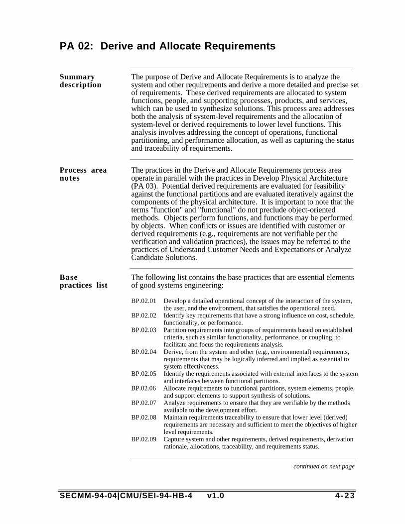
SECMM-94-04|CMU/SEI-94-HB-4 v1.0 4 -23
PA 02: Derive and Allocate Requirements
Summarydescription
The purpose of Derive and Allocate Requirements is to analyze thesystem and other requirements and derive a more detailed and precise setof requirements. These derived requirements are allocated to systemfunctions, people, and supporting processes, products, and services,which can be used to synthesize solutions. This process area addressesboth the analysis of system-level requirements and the allocation ofsystem-level or derived requirements to lower level functions. Thisanalysis involves addressing the concept of operations, functionalpartitioning, and performance allocation, as well as capturing the statusand traceability of requirements.
Process areanotes
The practices in the Derive and Allocate Requirements process areaoperate in parallel with the practices in Develop Physical Architecture(PA 03). Potential derived requirements are evaluated for feasibilityagainst the functional partitions and are evaluated iteratively against thecomponents of the physical architecture. It is important to note that theterms "function" and "functional" do not preclude object-orientedmethods. Objects perform functions, and functions may be performedby objects. When conflicts or issues are identified with customer orderived requirements (e.g., requirements are not verifiable per theverification and validation practices), the issues may be referred to thepractices of Understand Customer Needs and Expectations or AnalyzeCandidate Solutions.
Basepractices list
The following list contains the base practices that are essential elementsof good systems engineering:
BP.02.01 Develop a detailed operational concept of the interaction of the system,the user, and the environment, that satisfies the operational need.
BP.02.02 Identify key requirements that have a strong influence on cost, schedule,functionality, or performance.
BP.02.03 Partition requirements into groups of requirements based on establishedcriteria, such as similar functionality, performance, or coupling, tofacilitate and focus the requirements analysis.
BP.02.04 Derive, from the system and other (e.g., environmental) requirements,requirements that may be logically inferred and implied as essential tosystem effectiveness.
BP.02.05 Identify the requirements associated with external interfaces to the systemand interfaces between functional partitions.
BP.02.06 Allocate requirements to functional partitions, system elements, people,and support elements to support synthesis of solutions.
BP.02.07 Analyze requirements to ensure that they are verifiable by the methodsavailable to the development effort.
BP.02.08 Maintain requirements traceability to ensure that lower level (derived)requirements are necessary and sufficient to meet the objectives of higherlevel requirements.
BP.02.09 Capture system and other requirements, derived requirements, derivationrationale, allocations, traceability, and requirements status.
continued on next page
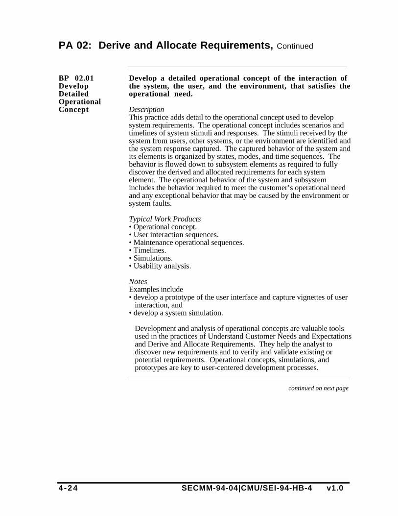
4 -24 SECMM-94-04|CMU/SEI-94-HB-4 v1.0
PA 02: Derive and Allocate Requirements, Continued
BP 02.01DevelopDetailedOperationalConcept
Develop a detailed operational concept of the interaction ofthe system, the user, and the environment, that satisfies theoperational need.
DescriptionThis practice adds detail to the operational concept used to developsystem requirements. The operational concept includes scenarios andtimelines of system stimuli and responses. The stimuli received by thesystem from users, other systems, or the environment are identified andthe system response captured. The captured behavior of the system andits elements is organized by states, modes, and time sequences. Thebehavior is flowed down to subsystem elements as required to fullydiscover the derived and allocated requirements for each systemelement. The operational behavior of the system and subsystemincludes the behavior required to meet the customer’s operational needand any exceptional behavior that may be caused by the environment orsystem faults.
Typical Work Products• Operational concept.• User interaction sequences.• Maintenance operational sequences.• Timelines.• Simulations.• Usability analysis.
NotesExamples include• develop a prototype of the user interface and capture vignettes of user
interaction, and• develop a system simulation.
Development and analysis of operational concepts are valuable toolsused in the practices of Understand Customer Needs and Expectationsand Derive and Allocate Requirements. They help the analyst todiscover new requirements and to verify and validate existing orpotential requirements. Operational concepts, simulations, andprototypes are key to user-centered development processes.
continued on next page

SECMM-94-04|CMU/SEI-94-HB-4 v1.0 4 -25
PA 02: Derive and Allocate Requirements, Continued
BP 02.02Identify KeyRequirementIssues
Identify key requirements that have a strong influence oncost, schedule, functionality, or performance.
DescriptionIn analyzing system and derived requirements, requirements are oftenidentified that have an especially strong influence on the cost,development schedule, or performance of a product. The total set ofrequirements are screened for potential key requirements. Theserequirements are referred to the process areas Analyze CandidateSolutions and Develop Physical Architecture for cost benefit analyses.The results of analyzing key requirements may be reviewed with thecustomer using the methods of understanding customer needs andexpectations. Key requirements that show a relatively low benefit tocost ratio are candidates for negotiation with the customer. Keyrequirements that show a high benefit to cost ratio are assessed for levelof difficulty and may be subject to risk management considerations.
Typical Work Products• Key requirements issues.• Benefit to cost sensitivity analyses for key requirements.
NotesAn example: Identify performance requirements that are near the limitsof what has been achieved before (near the state of the art).
The activities of identifying key requirements are closely related to theactivities of the process areas Understand Customer Needs andExpectations, Analyze Candidate Solutions, and Develop PhysicalArchitecture.
continued on next page

4 -26 SECMM-94-04|CMU/SEI-94-HB-4 v1.0
PA 02: Derive and Allocate Requirements, Continued
BP 02.03PartitionFunctions
Partition requirements into groups of requirements based onestablished criteria, such as similar functionality,performance, or coupling, to facilitate and focus therequirements analysis.
DescriptionRequirements are evaluated for similarity in function and grouped intoappropriate partitions. Criteria for appropriate functional partitions areestablished and may include, in addition to similarity, high couplingwithin functional partition and low coupling between functionalpartitions. Functional partitions are chosen so that overall performancerequirements can be budgeted to the functions.
Typical Work Products• Identified functional partitions.• Functional performance budgets.
NotesExamples include• group all requirements that apply to user interaction, and• group all requirements that apply to data storage and retrieval.
Functional partitions include functions and subfunctions whoserequirements are ultimately allocated to physical architecture elements.
continued on next page

SECMM-94-04|CMU/SEI-94-HB-4 v1.0 4 -27
PA 02: Derive and Allocate Requirements, Continued
BP 02.04DeriveRequire-ments
Derive, from the system and other (e.g., environmental)requirements, requirements that may be logically inferredand implied as essential to system effectiveness.
DescriptionDerived requirements are those requirements that are explicitly identifiedor discovered as necessary implications of stated system and other top-level requirements. A system requirement's derived requirements"represent" the system requirement in terms of development constraintsand verification. Typically, a system requirement may have to bedecomposed into one or more derived requirements in order to allocateresponsibility and to provide for feasible verification. Derivedrequirements apply to all aspects of the developed system, including thedevelopment, production, environmental, and operational parameters.Derived requirements may result from a single higher level requirementor partitions of higher level requirements.
Typical Work Products• Derived operational requirements assigned to a functional partition.• Derived performance requirements.
NotesExamples include• Assess system requirements for derived requirements relating to the
operational environment.• Produce derived requirements necessary to render system requirements
testable.• Produce derived requirements necessary to allocate system timing
budgets to functional partitions.• Produce rationale for derived requirements.
Derived functional and performance requirements are allocated directly,or as appropriate, to functional partitions, derived requirements, andultimately to physical architecture elements.
continued on next page
4 -28 SECMM-94-04|CMU/SEI-94-HB-4 v1.0
PA 02: Derive and Allocate Requirements, Continued
BP 02.05DevelopInterfaceRequirements
Identify the requirements associated with external interfacesto the system and interfaces between functional partitions.
DescriptionThe identification of external and internal interfaces is conductedthroughout the analysis of system requirements and is essential to thedevelopment of a complete set of requirements for the physicalarchitecture. The early and complete definition of external interfaces isespecially important in characterizing the overall functionality of thesystem because the interfaces are typically independent of the internalarchitecture and may be a driver of the internal architecture andfunctionality. This is especially true of the user interface. The internalinterfaces and their related derived requirements are identified inconjunction with the functional partitioning. After functional partitionsare identified, their interfaces and logical data flows are defined.
Typical Work Products• Interface requirements.
NotesExamples include• Identify the input and output data for each user interface function.• Identify the input and output data of all external systems that must
interface to the subject system.• Identify the physical requirements of all external system interfaces.• Identify need for physical mounting requirements• Identify operator stimuli and control points.• Identify signal and control structures.• Identify interfaces to the environment.
External stimuli identified in the Develop Detailed Operational Conceptbase practice (BP02.01) are candidates for external interfaces. Theidentification of external interfaces is facilitated by the development andunderstanding of the detailed operational concept. In addition, theidentification of external interfaces forms the basis for derived externalinterface requirements as well as many derived functional andperformance requirements. Interfaces are captured and controlledaccording to the practices of the Integrate System process area.
continued on next page
SECMM-94-04|CMU/SEI-94-HB-4 v1.0 4 -29
PA 02: Derive and Allocate Requirements, Continued
BP 02.06AllocateRequirements
Allocate requirements to functional partitions, systemelements, people, and support elements to supportsynthesis of solutions.
DescriptionThe purpose of this practice is to facilitate the separate development ofsystem elements and components at successively lower partitions.Requirements are initially allocated to functional partitions andsubfunctions and ultimately to system elements and components. Theallocations are performed so that the implementation of allocated derivedrequirements by the associated system elements is both necessary andsufficient to satisfy the higher level requirements. Where it appears thata requirement is to be satisfied jointly by several system elements, it isnecessary to derive from this joint requirement separate requirements foreach system element involved..
Alternatives should be considered relative to allocating requirements topeople versus systems. Support elements, including processes,production, maintenance, and environmental constraints should beevaluated for allocation of derived requirements.
Typical Work Products• Derived requirements.• Requirements allocation attributes.
NotesExamples include• Identify the requirements and derived requirements that apply to all
system elements and allocate these requirements to all elements.• Identify requirements and derived requirements that constitute a
performance partition and uniquely allocate these requirements to theappropriate system element.
Allocations of functional and performance requirements facilitate thedivision of responsibilities for development and testing. The practicesof the process areas Understand Customer Needs and Expectations,Derive and Allocate Requirements, and Develop Physical Architectureiterate the allocation of requirements.
continued on next page

4 -30 SECMM-94-04|CMU/SEI-94-HB-4 v1.0
PA 02: Derive and Allocate Requirements, Continued
BP 02.07EnsureRequirementVerifiability
Analyze requirements to ensure that they are verifiable bythe methods available to the development effort.
DescriptionThe method and feasibility of verifying requirements is established earlyin the development cycle. It is essential for a system or derivedrequirement to have the characteristics indicating that it can be verified inorder to prove that the resulting product meets the intended purpose.Evaluating the feasibility of verifying a potential requirement facilitatesproducing good requirements. Throughout the life cycle, requirementsare continually assessed to ensure the feasibility of verification,especially in connection with evaluating changes to requirements.Methods of verification include inspection, test, demonstration, andanalysis.
Typical Work Products• Verifiability status of requirements.• Captured verification method.
NotesAn example: Assess the verification feasibility for each requirement.
It is important to ensure that requirements verification is performediteratively and recursively with the practices of verification andvalidation.
continued on next page

SECMM-94-04|CMU/SEI-94-HB-4 v1.0 4 -31
PA 02: Derive and Allocate Requirements, Continued
BP 02.08MaintainRequirementSufficiencyandTraceability
Maintain requirements traceability to ensure that lower level(derived) requirements are necessary and sufficient to meetthe objectives of higher level requirements.
DescriptionThis practice captures, maintains, and controls the traceability and statusof requirements throughout the product life cycle. Of particularimportance is the relationship between higher level requirements andtheir associated derived requirements, which in effect represent thehigher level requirement. This dependence of derived requirements onother requirements or design features is called traceability and isrecorded and maintained from the highest level (most general) to thelowest level (most specific) as the requirements and design evolve. Acontinuous assessment of the lower level requirements and the validityof their traceability is conducted to ensure that the developed system orproduct meets all the requirements, but does not have features beyondwhat is necessary to meet the requirements.
Typical Work Products• Requirement exception report.• Requirement traceability tables.• Requirements databases.• Traceability exception report.
NotesExamples include• Perform analyses to ensure that related sets of derived requirements,
taken as a whole, meet the intent of the parent requirement.• Perform analyses to ensure that there are no unnecessary requirements.• Verify requirements traceability.
All practices involving the creation, change, or verification ofrequirements (especially those of the process areas UnderstandCustomer Needs and Expectations, Derive and Allocate Requirements,Develop Physical Architecture, and Verify and Validate System) mustmaintain requirements traceability.
continued on next page
4 -32 SECMM-94-04|CMU/SEI-94-HB-4 v1.0
PA 02: Derive and Allocate Requirements, Continued
BP 02.09CaptureResults andRationale
Capture system and other requirements, derivedrequirements, derivation rationale, allocations, traceability,and requirements status.
DescriptionThe capture of requirements, requirement partitions, derivedrequirements, requirement allocations, traceability, rationale, and statusinformation, along with the dissemination and control of thisinformation, forms the basis for systematically developing and verifyinga system that meets the customer's operational and performanceexpectations within acceptable constraints of cost and schedule.Captured results also include other attributes of requirements such as aunique requirement number, interpretation, test method, issues, andacceptance/change status.
Typical Work Products• Requirement document.• Requirements databases.• Interface requirements document.• Functional architecture.• Requirement allocation sheet.
NotesExamples include• Enter requirements, their traceability, allocation and status into a
requirements data base.• Distribute, review and coordinate requirements data with the
development team.
The collection of work products from this process area is sometimescalled the functional architecture.
The capture of results and rationale applies to all the practices associatedwith the derivation and allocation of requirements as well as the analysisof candidate solutions and design decisions.
End of PA 02: Derive and Allocate Requirements

SECMM-94-04|CMU/SEI-94-HB-4 v1.0 4 -33
PA 03: Develop Physical Architecture
Summarydescription
The purpose of Develop Physical Architecture is to transform thefunctional architecture, as defined by the Derive and AllocateRequirements process area, into the physical architecture for the system.It involves deriving the physical architecture requirements, identifyingthe key design issues, determining the physical structure and interfaces,and allocating the physical architecture requirements. The practicesdescribed herein are expected to be performed iteratively until the designis handed off to the implementing or component engineering disciplines.
Process areanotes
This process area generates candidate solutions and then makes use ofthe Analyze Candidate Solutions process area to choose an alternativethat meets the needs of Develop Physical Architecture. This processarea is performed iteratively with the process areas UnderstandCustomer Needs and Expectations and Derive and AllocateRequirements.
Basepractices list
The following list contains the base practices that are essential elementsof good systems engineering: BP.03.01 Derive the requirements for the physical architecture.BP.03.02 Identify the key design issues that must be resolved to support successful
development of the system.BP.03.03 Generate physical structure alternative(s) and constraints, and select a
solution in accordance with the Analyze Candidate Solutions processarea.
BP.03.04 Develop the physical architecture’s interface requirements for the chosenphysical structure.
BP.03.05 Allocate the physical architecture requirements to the chosen physicalstructure.
BP.03.06 Maintain requirements traceability for the physical architecturerequirements to ensure that lower level (derived) requirements arenecessary and sufficient to meet the needs of higher level requirements ordesign.
BP.03.07 Describe the physical architecture by capturing the design results andrationale.
continued on next page

4 -34 SECMM-94-04|CMU/SEI-94-HB-4 v1.0
PA 03: Develop Physical Architecture, Continued
BP 03.01DerivePhysicalArchitectureRequirements
Derive the requirements for the physical architecture.
DescriptionThis activity makes use of and iterates with a number of other activities,including development of system requirements, and makes use of otherstates, including the current state of the system functional and physicalarchitectures. Derived requirements may include requirements takendirectly from the system requirements, as well as requirements that areinferred from the system requirements, either directly or as constrainedby the current architectures. Derived requirement types includeperformance, human interaction, production, maintenance, etc. Derivedrequirements may be applicable broadly or they may be applicable tospecific subsystems or support elements.
Typical Work Products• Derived architecture requirements.
NotesDerived requirements for the system’s physical architecture apply to theactual subsystems, configuration items, or components as distinguishedfrom functional or notional applicability.
BP 03.02Identify KeyDesignIssues
Identify the key design issues that must be resolved tosupport successful development of the system.
DescriptionThe design activity must begin with an awareness of the many issuesfacing the system development. An evaluation must take place todetermine what subset of the many issues are the design drivers for thesystem. This subset of key design issues then becomes a constraint onthe system design and development.
Typical Work Products• List of key design issues.
NotesKey design issues may include cost drivers, performance drivers, risk,or technology. In an integrated product development team environment,key design issues may identify the need for "specialty engineers" to be apart of the design team. There may be issues seemingly unrelated to thesystem that become key design issues. An example of such an issue iscompliance with governmental laws governing the manufacturing ordisposal of a product.
continued on next page

SECMM-94-04|CMU/SEI-94-HB-4 v1.0 4 -35
PA 03: Develop Physical Architecture, Continued
BP 03.03DevelopPhysicalStructure
Generate physical structure alternative(s) and constraints,and select a solution in accordance with the practices of theAnalyze Candidate Solutions process area.
DescriptionA physical structure for the system is developed that satisfies theselected functional architecture. The system’s physical structureincludes subsystems, configuration items, or components, as well astheir interrelationships, which are to be developed to meet therequirements.
Typical Work Products• Physical structure.• Subsystems.• Major assemblies.• Identified interfaces.
NotesThe identified elements of the system’s physical structure constitute themajor “pieces” of the system to be developed, upgraded, maintained, orintegrated. For new development, these elements are optimally selectedthrough the analysis of alternatives against established requirements orcriteria. In the case of reuse or upgrades of existing systems, anexisting physical structure or its elements may be a requirement.
BP 03.04DevelopPhysicalInterfaceRequirements
Develop the physical architecture’s interface requirementsfor the chosen physical structure.
DescriptionExternal and internal interfaces are identified that allow development of acomplete set of physical architecture requirements. Alternative solutionsthat satisfy interface constraints are developed. A solution is selected inaccordance with the practices of the Analyze Candidate Solutionsprocess area.
Typical Work Products• Interface requirements.• User interface requirements.• Environmental interface requirements.• Subsystem interface requirements.
continued on next page

4 -36 SECMM-94-04|CMU/SEI-94-HB-4 v1.0
PA 03: Develop Physical Architecture, Continued
BP 03.04DevelopPhysicalInterfaceRequirements,continued
NotesThe physical architecture’s interface requirements can be broadlyclassified as those interface requirements between system elements andentities external to the system, and those among elements of the selectedphysical architecture. Generally, all or part of the external interfacerequirements may be known prior to selection of the physicalarchitecture. Internal interface requirements are typically deferred untilafter selection of the physical architecture.
BP 03.05AllocatePhysicalRequirements
Allocate the physical architecture requirements to thechosen physical structure.
DescriptionDerived requirements, functions or objects are allocated to physicalelements, as well as interfaces. Performance of the design is analyzed,and the physical architecture is refined and modified as necessary.
Typical Work Products• Allocated requirements.
NotesExamples include• Identify the requirements and derived requirements that apply to all
system elements and allocate these requirements to all elements.• Identify requirements and derived requirements that constitute a
performance partition and allocate these requirements to theappropriate system element.
continued on next page

SECMM-94-04|CMU/SEI-94-HB-4 v1.0 4 -37
PA 03: Develop Physical Architecture, Continued
BP 03.06MaintainRequirementSufficiencyandTraceability
Maintain requirements traceability for the physicalarchitecture requirements to ensure that lower level(derived) requirements are necessary and sufficient to meetthe needs of higher level requirements or design.
DescriptionThis practice captures, maintains, and controls the traceability and statusof requirements throughout the product life cycle. Derived requirementslevied on the physical architecture must result from, and trace to, higherlevel system requirements, functional requirements derived from thehigher level requirements, or higher level design decisions. Thistraceability is recorded and maintained from the highest level (mostgeneral) to the lowest level (most specific) as the requirements anddesign evolve. An assessment of the lower level physical architecturerequirements and the validity of their traceability is conductedcontinuously to ensure that the developed system or product meets allthe requirements, but does not have features beyond what is necessaryto meet the requirements.
Typical Work Products• Requirement traceability tables.• Requirement exception report.• Traceability exception report.• Requirement database.
NotesThe complete requirements traceability relationships include allrequirements levied on the system and its parts as the solution evolves.Thus, requirements derived from a valid functional analysis and themore detailed requirements derived for the physical architecture arecaptured in the same traceability data set.
Examples include• Perform analysis to ensure that related sets of derived requirements,
taken as a whole, meet the intent of the parent requirement.• Perform analysis to ensure there are no unnecessary requirements.
continued on next page

4 -38 SECMM-94-04|CMU/SEI-94-HB-4 v1.0
PA 03: Develop Physical Architecture, Continued
BP 03.07CaptureResults andRationale
Describe the physical architecture by capturing the designresults and rationale.
DescriptionThe captured physical architecture includes the physical architectureelements, their relationships, interfaces, allocated derived requirements,requirements traceability, and the rationale supporting the selectedsolution. The rationale for the design and architectural decisions drawsheavily on the results of analyzing alternatives against establishedcriteria and requirements. The capture, baselining, and dissemination ofthe physical architecture description is essential to developing andverifying a system that meets the customers’ operational andperformance expectations.
Typical Work Products• Physical architecture.• Interface requirements.• Requirement allocations.• Design documents.• Requirements traceability table.
NotesExamples of ways to capture the design results and rationale include• design document,• specification,• interface control drawing,• engineering notebook entries,• block diagrams, and• data flow or control flow diagrams.
End of PA 03: Develop Physical Architecture

SECMM-94-04|CMU/SEI-94-HB-4 v1.0 4 -39
PA 04: Integrate Disciplines
Summarydescription
The purpose of Integrate Disciplines is to identify those disciplinesnecessary for effective system development and create an environmentin which they jointly and effectively work together toward a commonagenda. Each discipline’s unique expertise and concerns are forwardedand considered, but the focus on total system development ismaintained. These disciplines may include, but are not limited to,marketing, manufacturing, component design, development (e.g.,hardware, software, or firmware), reliability, maintainability,supportability, human factors, logistics, safety, and security. It iscritical to be able to meld such disciplines without sacrificing theirparochial interests concerning issues important to and unique to eachdiscipline. This environment must persist throughout the systemdevelopment life cycle.
Process areanotes
It is essential to sustain a focus on the human interaction activities andissues related to cooperative group dynamics during the development,synthesis, and integration efforts. In many cases, the “systemsengineer” role, in this environment, is to function as an “informationbroker,” coordinating and distributing information through thedevelopment staff. The goal is to eliminate nonessential informationwhile providing essential information to members of the developmentstaff, on a timely basis.
Basepractices list
The following list contains the base practices that are essential elementsof good systems engineering: BP.04.01 Identify the disciplines that are directly or indirectly essential to system
development.BP.04.02 Familiarize individuals involved in the development effort with the
various disciplines and their roles in creating a successful system.BP.04.03 Actively promote cross-discipline understanding within the development
team.BP.04.04 Establish methods for interdisciplinary coordination.BP.04.05 Establish methods for identifying and resolving interdisciplinary issues.BP.04.06 Follow established interdisciplinary methods to achieve integrated
solutions to identified issues or problems.BP.04.07 Communicate results of interdisciplinary activities to affected groups.BP.04.08 Develop project goals and ensure that each project member and direct
support person is fully aware of them.
continued on next page
4 -40 SECMM-94-04|CMU/SEI-94-HB-4 v1.0
PA 04: Integrate Disciplines, Continued
BP 04.01IdentifyEssentialDisciplines
Identify the disciplines that are directly or indirectlyessential to system development.
DescriptionEfficient and effective systems result from a blending of the efforts ofpeople from many unique disciplines. The earlier that affecteddisciplines can be identified and their input into the development effortcaptured, the more satisfying the product will be to both thedevelopment and user community.
Typical Work Products• Roster of essential disciplines.• List of representatives from each discipline.
NotesAs the development effort proceeds through its life cycle, the number ofcritical disciplines is a variable. The initial focus should be on attainingcomplete coverage, not limiting participants. Disciplines not affectedwill usually eliminate themselves from the roster, over time. However,the systems engineer must be cognizant enough of the concerns of alldisciplines so that he or she can recall specialists when neededthroughout the development life cycle.
BP 04.02TrainInterdiscip-linary Roles
Familiarize individuals involved in the development effortwith the various disciplines and their roles in creating asuccessful system.
DescriptionEach individual must be introduced to the roles and responsibilities thatthe various representatives from the essential disciplines have in thedevelopment effort. The contribution that each representative makes tothe effort should be clear. How the group, as a whole, melds thoseunique contributions in an effective system solution should beunderstood and practiced.
Typical Work Products• Description of roles, responsibilities, and functions of representatives.
continued on next page

SECMM-94-04|CMU/SEI-94-HB-4 v1.0 4 -41
PA 04: Integrate Disciplines, Continued
BP 04.02TrainInterdiscip-linary Roles,continued
NotesIt is extremely important to encourage informal interaction betweenrepresentatives from the various disciplines. The synergism resultingfrom social situations (e.g., the discussion of design problems overcoffee or lunch) creates an atmosphere of group collaboration rather thangroup competition and/or placing blame or responsibility for problemson other groups and individuals. Formal meetings being the only venuefor communication can often reinforce competitive behaviors. One ofthe most difficult tasks confronting a systems engineer is to create acollaborative atmosphere in the formal meeting situation.
BP 04.03Foster Cross-DisciplineUnderstand-ing
Actively promote cross-discipline understanding within thedevelopment team.
DescriptionMembers of the development team need to become familiar with theissues that are important to the disciplines essential to the systemdevelopment and the effect each discipline has on the quality of theproduct. The systems engineer is a natural avenue to provide anoverview of the primary focus of and the issues of concern to eachdiscipline involved with the development effort. To illustrate thatconsideration of the specialty disciplines is key to product success, itmay help to show the time-critical nature of some of the decisions madeearly in the development life cycle and how they can produce positive ornegative customer impressions when the system is introduced to itsintended environment.
Typical Work Products• Pamphlets describing each discipline.• Briefings to familiarize the development team with lessons learned.
NotesThis is often one of the most overlooked areas in the list of systemsengineering tasks; yet if often produces the highest return on investmentin terms of cost-effective solutions to development problems.Understanding the other individuals’ concerns is the first step toachieving a cooperative, harmonious work environment, so it is difficultto focus too much effort in this area. The caution is to remember thatthe objective is not to create a group who are experts in all thedisciplines, rather, it is to create a group of individuals who are aware ofeach others' technical concerns and how proper consideration of eachconcern has a positive impact on the quality of the group’s product.
continued on next page
4 -42 SECMM-94-04|CMU/SEI-94-HB-4 v1.0
PA 04: Integrate Disciplines, Continued
BP 04.03Foster Cross-DisciplineUnderstand-ing, continued
Examples include• Hold a meeting at the inception of the project/program at which
representatives of the identified development disciplines share theirissues.
• Summarize the issues of each discipline in a one- or two-page paper.• Distribute this paper to all.
BP 04.04EstablishCoordinationMethods
Establish methods for interdisciplinary coordination.
DescriptionIn addition to the roles and what information to share, members of theproduct development team must know how to share knowledge, i.e.,the particular nuts and bolts of getting information from an individual orgroup to others who need it.
Typical Work Products• Integrated development coordination methods.
NotesKnowledge sharing may center around an automation strategy, in whichcase individuals would share knowledge through the automation toolsuite.
Knowledge sharing may center around a teaming strategy, in which caseindividuals would share knowledge in accordance with the particularteaming structures used.
continued on next page

SECMM-94-04|CMU/SEI-94-HB-4 v1.0 4 -43
PA 04: Integrate Disciplines, Continued
BP 04.05EstablishResolutionMethods
Establish methods for identifying and resolvinginterdisciplinary issues.
DescriptionIssues will arise during product development for which there is nosimple solution. Pre-determined methods of resolving these issues mustbe known to the product development staff. Several resolutiontechniques must be available. The technique used would depend onseveral factors, including the time available to come to resolution, theseverity of the issue, and the related consequences of the issue.
Typical Work Products• Issue resolution methods.
NotesExamples include• Pugh's Controlled Convergence technique,• quality function deployment technique,• autocratic ediction, and• arbitration and rules.
BP 04.06U s eInterdiscip-linaryMethods
Follow established interdisciplinary methods to achieveintegrated solutions to identified issues or problems.
DescriptionThe product development staff must use the established methods toresolve issues. Attempts to circumvent the methods must bediscouraged or incorporated (if the alternate method is agreed to besuperior).
Typical Work Products• Reports.
continued on next page
4 -44 SECMM-94-04|CMU/SEI-94-HB-4 v1.0
PA 04: Integrate Disciplines, Continued
BP 04.07CommunicateResults
Communicate results of interdisciplinary activities toaffected groups.
DescriptionThe work of product development is making decisions. These decisionsmust be communicated to members of the product development staffwho must make more decisions.
Typical Work Products• Results of interdisciplinary activities.
NotesExamples include• electronic mail decisions with rationale, and• use of the facilities of the project's selected automation tool set.
BP 04.08Develop andCommunicateProjectGoals
Develop project goals and ensure that each project memberand direct support person is fully aware of them.
DescriptionFor the product development to proceed with reasonable smoothness,each project member and the direct support staff must know and worktoward the same goals. These goals must be clearly developed andcommunicated to every member of the staff.
Typical Work Products• Project objectives.
NotesExamples include• a cost/schedule goal,• a quality/cost goal, and• a quality/schedule goal.
End of PA 04: Integrate Disciplines

SECMM-94-04|CMU/SEI-94-HB-4 v1.0 4 -45
PA 05: Integrate System
Summarydescription
The purpose of Integrate System is to ensure that system elements willfunction as a whole. This primarily involves identifying, defining, andcontrolling interfaces, as well as verifying system functions that requiremultiple system elements. The activities associated with IntegrateSystem occur throughout the entire life cycle of system development.
Process areanotes
The Integrate System activities begin early in the development effort,when interface requirements can be influenced by all engineeringdisciplines and applicable interface standards can be invoked. Theycontinue through design and checkout. During design, emphasis is onensuring that interface specifications are documented andcommunicated. During system element checkout, both prior toassembly and in the assembled configuration, emphasis is on verifyingthe implemented interfaces. Throughout the integration activities,interface baselines are controlled to ensure that changes in the design ofsystem elements have minimal impact on other elements to which theyinterface. During testing, or other validation and verification activities,multiple system elements are checked out as integrated subsystems orsystems.
There can appear to be some redundancy between the processcharacteristics captured in this process area and some of those inDevelop Physical Architecture (PA 03). However, the emphasis in PA03 is to generate alternatives and select a solution, while the emphasis inthis process area is to develop a detailed description of interfaces. Theimportance of interfaces is also emphasized in this process area.
The process characteristics captured in this process area runconcurrently, iteratively, and/or recursively with other processcharacteristics captured in other process areas.
continued on next page

4 -46 SECMM-94-04|CMU/SEI-94-HB-4 v1.0
PA 05: Integrate System, Continued
Basepractices list
The following list contains the base practices that are essential elementsof good systems engineering: BP.05.01 Develop detailed descriptions of the interfaces implied by the system
architecture.BP.05.02 Communicate the interface definitions and coordinate change requests
with all system element developers who could be affected by interfacechanges.
BP.05.03 Verify the receipt of each system element required to assemble thesystem in accordance with the physical architecture.
BP.05.04 Verify the implemented design features of developed or purchased systemelements against their requirements.
BP.05.05 Verify that the system element interfaces comply with the interfacerequirements prior to assembly.
BP.05.06 Assemble aggregates of system elements in accordance with theestablished integration strategy.
BP.05.07 Check the integrated system interfaces in accordance with the establishedintegration strategy.
BP.05.08 Develop an integration strategy and supporting documentation whichidentifies the optimal sequence for receipt, assembly, and activation ofthe various components that make up the physical architecture of thesystem.
BP 05.01DefineInterfaces
Develop detailed descriptions of the interfaces implied bythe system architecture.
DescriptionSystem and subsystem interfaces are defined as early as possible in thedevelopment effort. Interface descriptions address logical, physical,electrical, mechanical, and environmental parameters as appropriate. Thebulk of integration problems arise from unknown or uncontrolledaspects of interfaces. Intra-system interfaces are the first designconsideration for developers of the system's subsystems. Interfaces areused from previous development efforts or are developed in accordancewith interface standards for the given discipline or technology. Novelinterfaces are constructed only for compelling reasons.
Typical Work Products• Interface descriptions.
continued on next page

SECMM-94-04|CMU/SEI-94-HB-4 v1.0 4 -47
PA 05: Integrate System, Continued
BP 05.02ControlInterfaces
Communicate the interface definitions and coordinatechange requests with all system element developers whocould be affected by interface changes.
DescriptionThis practice is intended to ensure that the interfaces of each element ofthe system or subsystem are controlled and known to the developers.Additionally, when changes to the interfaces are needed, the changesmust at least be evaluated for possible impact to other interfacingelements and then communicated to the affected developers. Althoughall affected developers are part of the group that makes changes, suchchanges need to be captured in a readily accessible place so that thecurrent state of the interfaces can be known. Designs are audited toverify compliance with the defined interface requirements.
Typical Work Products• Interface control documents.• Exception reports.
NotesThe change control and coordination mechanism could take the form ofan interface change control board with direct feed to configurationmanagement services.
BP 05.03VerifyReceipt ofSystemElements
Verify the receipt of each system element required toassemble the system in accordance with the physicalarchitecture.
DescriptionThis practice is intended to ensure that each element of the system orsubsystem is received. The elements are checked for quantity, obviousdamage, and consistency between the element description and a list ofrequired elements. Some method of assessing the timeliness of receiptof system elements will need to be in place.
Typical Work Products• Acceptance documents.• Delivery receipts.• Checked packing list.
NotesAn example activity is to check the packing list against the receiveditems.
continued on next page
4 -48 SECMM-94-04|CMU/SEI-94-HB-4 v1.0
PA 05: Integrate System, Continued
BP 05.04VerifySystemElementCorrectness
Verify the implemented design features of developed orpurchased system elements against their requirements.
DescriptionThis practice is intended to ensure that each element of the system orsubsystem functions in its intended environment. Such verification maybe by test, inspection, analysis, etc., and may be executed by theorganization that will assemble the system or sub-system or by theproducing organization. Some method of discerning the elements that"passed" verification from those elements that "failed" will need to be inplace.
Typical Work Products• Validated system elements.• Exception reports.
NotesExamples include• Inspect and/or test elements.• Prepare deficiency or compliance reports.• Use regression testing as a tool as subsystems/elements are combined.• Verify that elements meet requirements before shipping by
manufacturer/supplier.
BP 05.05VerifySystemElementInterfaces
Verify that the system element interfaces comply with theinterface requirements prior to assembly.
DescriptionThis practice is intended to ensure that the interface of each element ofthe system or subsystem is verified against its corresponding interfacedefinition. Such verification may be by test, inspection, analysis, etc.,and may be executed by the organization that will assemble the systemor subsystem or by another organization. Some method of discerningthe elements that "passed" verification from those elements that "failed"will need to be in place.
Typical Work Products• Verified system element interfaces.• Test reports.• Exception reports.
NotesExamples include• Elements are inspected and/or tested to verify that the interfaces were
implemented in accordance with the defined interface requirements.• Compliance or deficiency reports are prepared.
continued on next page

SECMM-94-04|CMU/SEI-94-HB-4 v1.0 4 -49
PA 05: Integrate System, Continued
BP 05.06AssembleAggregatesof SystemElements
Assemble aggregates of system elements in accordance withthe established integration strategy.
DescriptionThis practice is intended to ensure that the assembly of the systemelements into larger or more complex assemblies is conducted inaccordance with the planned strategy. Testing of the aggregates isexplicitly addressed in the Verify and Validate System process area, andis to occur as needed here.
Typical Work Products• Integration reports.• Exception reports.
NotesExamples include• subsystem build, and• subsystem test.
BP 05.07CheckAggregateof SystemElements
Check the integrated system interfaces in accordance withthe established integration strategy.
DescriptionThis practice is intended to ensure that the assembly of the systemelements into the final system is conducted and tested in accordance witha planned strategy. System testing is explicitly addressed in the Verifyand Validate System process area, and is to occur as needed here.
Typical Work Products• Integration reports.• Integrated system.
NotesAn example: Verify system behavior.
continued on next page

4 -50 SECMM-94-04|CMU/SEI-94-HB-4 v1.0
PA 05: Integrate System, Continued
BP 05.08DevelopIntegrationStrategy
Develop an integration strategy and supportingdocumentation which identifies the optimal sequence forreceipt, assembly, and activation of the various componentsthat make up the physical architecture of the system.
DescriptionUsing business as well as technical factors, the strategy must focus onthe need for an assembly, activation, and loading sequence thatminimizes cost and assembly difficulties. The larger or more complexthe system or the more delicate its elements, the more critical the propersequence becomes, as small changes can cause large impacts on projectresults.
The optimal sequence of assembly is built from bottom-up ascomponents become subelements, elements, and subsystems, each ofwhich must be checked prior to fitting into the next higher assembly.The sequence will encompass any effort needed to establish and equipthe assembly facilities (e.g., raised floor, hoists, jigs, test equipment,I/O, and power connections). Once established, the sequence must beperiodically reviewed to ensure that variations in production anddelivery schedules have not had an adverse impact on the sequence orcompromised the factors on which earlier decisions were made.
Typical Work Products• Integration strategy document.• Assembly/check area drawings.• System/component documentation.• Selected assembly sequence and rationale.
NotesExample contents of a strategy document include• personnel requirements,• assembly area drawings,• special handling,• system documentation for systems engineering users,• shipping schedule,• assembly sequence and rationale, and• test equipment and drivers.
End of PA 05: Integrate System
SECMM-94-04|CMU/SEI-94-HB-4 v1.0 4 -51
PA 06: Understand Customer Needs and Expectations
Summarydescription
The purpose of Understand Customer Needs and Expectations is toelicit, stimulate, analyze, and communicate customer needs andexpectations to obtain a better understanding of what will satisfy thecustomer. Understand Customer Needs and Expectations involvesengaging the customer or their surrogate in ongoing dialogue designedto translate his/her needs and expectations into a verifiable set ofrequirements which the customer understands and which provide thebasis for agreements between the customer and the systems engineeringeffort.
Process areanotes
Since this process area supports the dialogue between systemsengineering and the customer, all other process areas will use it to keepthe customer informed throughout the project life cycle.
Customer, as used here, denotes either a directly contracted customer ora customer surrogate who represents a particular market segment in amarket-driven, multi-customer industry.
Basepractices list
The following list contains the base practices that are essential elementsof good systems engineering: BP.06.01 Elicit customer needs, expectations, and measures of effectiveness.BP.06.02 Analyze customer needs and expectations to develop a preliminary
operational concept of the system as appropriate.BP.06.03 Develop a statement of system requirements.BP.06.04 Obtain concurrence from the customer that the agreed upon customer
requirements satisfy their needs and expectations.BP.06.05 Inform the customer on a regular basis about the status and disposition
of needs, expectations, and measures of effectiveness.
continued on next page

4 -52 SECMM-94-04|CMU/SEI-94-HB-4 v1.0
PA 06: Understand Customer Needs and Expectations, Continued
BP 06.01Elicit Needs
Elicit customer needs, expectations, and measures ofeffectiveness.
DescriptionFrequently, customer needs and expectations are poorly identified orconflicting. The needs and expectations, as well as customerlimitations, must be clearly identified and prioritized. An iterativeprocess to accomplish this is used throughout the life of the project.During this process, an effort is made to identify any unique end-userneeds and expectations which may exist, and to obtain customerapproval to include them, or justification for their omission. In the caseof non-negotiated situations, the surrogate for the end-user or customeris frequently the customer relations or marketing part of theorganization.
Typical Work Products• Technical performance parameters.• Needs statement.
NotesExamples of techniques to elicit needs include• Joint Applications Design (JAD) meetings;• interface control working groups;• technical control working groups;• interim program reviews;• questionnaires, interviews, operational scenarios obtained from users;• prototypes and models;• brainstorming;• quality function development (QFD);• market surveys;• beta testing;• extraction from documents, standards, specs., etc.; and• observation of existing systems, environments, and workflow
patterns.
continued on next page
SECMM-94-04|CMU/SEI-94-HB-4 v1.0 4 -53
PA 06: Understand Customer Needs and Expectations, Continued
BP 06.02AnalyzeNeeds
Analyze customer needs and expectations to develop apreliminary operational concept of the system asappropriate.
DescriptionAnalysis is performed to determine what impact the intended operationalenvironment will have on the ability to satisfy the customer’s needs andexpectations. Feasibility, mission needs, cost constraints, potentialmarket size, etc., must all be taken into account, depending on theproduct context. The objective of the analysis is to determine systemconcepts that will satisfy the customer needs and expectations and thentranslate these concepts into top-level system requirements. In parallelwith this activity, the parameters that will be used to evaluate systemeffectiveness are determined based on customer input and thepreliminary system concept.
Typical Work Products• Operational concept.• System concept.• System cost.• Technical parameters.• Market segment description.
NotesSystems engineers must often help the customer formulate completeconcepts. Customer needs and expectations may need to be probed todetermine that adequate understanding and correct prioritization hasoccurred.
Expression of the logistics concept, support concept, maintenanceconcept, training concept, etc., are ways to capture system needs forfeedback to the customer.
Examples of formal methodologies used to analyze needs include• Quality function deployment (QFD),• trade studies,• mathematical techniques (design of experiments, sensitivity analysis,
timing, sizing, Monte Carlo simulation),• and prototype.
continued on next page

4 -54 SECMM-94-04|CMU/SEI-94-HB-4 v1.0
PA 06: Understand Customer Needs and Expectations, Continued
BP 06.03DevelopSystemRequirements
Develop a statement of system requirements.
DescriptionOnce a complete set of customer needs and expectations and apreliminary operational and system concept are available, these aretranslated into top-level system requirements.
Typical Work Products• System requirements.
NotesSystem requirements may be initially provided by the customer. In thiscase, systems engineering performs a "validation" of theserequirements, finding the inconsistencies or holes, and adds to them asnecessary. In other cases, the system engineering effort creates theentire set of system requirements.
System requirements may be documented formally using a customerspecified format or internal company standard, or they may beinformally captured.
BP 06.04ObtainConcurrence
Obtain concurrence from the customer that the agreed uponsystem requirements satisfy their needs and expectations.
DescriptionCustomer concurrence on interpretation of needs, operations concept,results of analyses, and translation of needs into system requirements isobtained initially via extensive communication, and theseunderstandings to which the customer committed are updatedthroughout the life of the project.
Typical Work Products• Validated system requirements.
continued on next page

SECMM-94-04|CMU/SEI-94-HB-4 v1.0 4 -55
PA 06: Understand Customer Needs and Expectations, Continued
BP 06.04ObtainConcurrence,continued
NotesExamples of forums to obtain customer concurrence include• working groups,• formal program reviews,• payment milestones,• in-process reviews,• status meetings,• weekly telephone conferences• focus groups, and.• beta tests.
Results of trade studies and/or feasibility studies can be presented to thecustomer to elicit their preferred approach.
BP 06.05InformCustomer
Inform the customer on a regular basis about the status anddisposition of needs, expectations, and measures ofeffectiveness.
DescriptionCommunication with the customer is particularly crucial while customerneeds are being analyzed and decisions on general approaches are beingmade. A key aspect of refining the common understanding of customerneeds and expectations is communicating the results of preliminaryanalysis and obtaining the customer’s feedback. Informing thecustomer continues throughout the life of the project. Another aspect ofbuilding customer understanding could be eliciting and stimulating newneeds.
Typical Work Products• Technical interchange minutes.• Prototypes.
NotesExamples of forums to inform the customer include• working groups,• normal program reviews,• payment milestones,• in-process reviews,• status meetings,• weekly telephone conferences,• focus groups, and• beta tests.
End of PA 06: Understand Customer Needs and Expectations

4 -56 SECMM-94-04|CMU/SEI-94-HB-4 v1.0
PA 07: Verify and Validate System
Summarydescription
The purpose of Verify and Validate System is to ensure that thedeveloper/supplier team performs increasingly comprehensiveevaluations to ensure that evolving work products will meet allrequirements. The activities associated with Verify and Validate Systembegin early in the development, address all work products (includingrequirements and design), and continue through system elementdevelopment and integration. The scope of verification coversdevelopment of the full system, as well as its production, operation andsupport. Validation involves evaluation of the customer requirementsagainst customer needs and expectations, and evaluation of the deliveredsystem to meet the customer's operational need in the mostrepresentative environment achievable.
Process areanotes
Means of evaluation associated with verification and validation includeinspection, analysis, demonstration, prototyping, simulation, andtesting. Evaluation begins early in the development process to ensurethat requirements and specifications are correct from the highest levelsas they are allocated downward (top-down); later, it becomes a bottom-up integration from the lowest level through each higher level ofintegration to cover the full system and its associated manufacturingprocesses and procedures.
Verification and validation address the work products of the processareas Understand Customer Needs and Expectations, Analyze CandidateSolutions, Derive and Allocate Requirements, Develop PhysicalArchitecture, and Integrate System. In many environments, the term“test” is used to encompass the concepts included in verification andvalidation. Corrective actions resulting from verification and validationare monitored in PA 11: Monitor and Control Technical Effort.
Validation is a formal evaluation in the most realistic operationalenvironment achievable, including personnel, procedures, and logisticalsupport.
continued on next page

SECMM-94-04|CMU/SEI-94-HB-4 v1.0 4 -57
PA 07: Verify and Validate System, Continued
Basepractices list
The following list contains the base practices that are essential elementsof good systems engineering:
BP.07.01 Establish plans for verification and validation that identify the overallrequirements, objectives, resources, facilities, special equipment, andschedule applicable to the system development.
BP.07.02 Define the methods, process, reviews, inspections, and tests by whichincremental products are verified against established criteria orrequirements established in a previous phase.
BP.07.03 Define the methods, process, and evaluation criteria by which the systemor product is verified against the system or product requirements.
BP.07.04 Define the methods, process, and evaluation criteria by which the systemor product will be validated against the customer’s needs andexpectations.
BP.07.05 Perform the verification and validation activities that are specified by theverification and validation plans and procedures, and capture the results.
BP.07.06 Compare the collected test, inspection, or review results with establishedevaluation criteria to assess the degree of success.
BP 07.01EstablishVerificationandValidationPlans
Establish plans for verification and validation that identifythe overall requirements, objectives, resources, facilities,special equipment, and schedule applicable to the systemdevelopment.
DescriptionThe purpose of developing plans for verification and validation activitiesis to establish the requirements, objectives, resources, facilities, specialequipment, and schedule for coordination among the development teamand with the customer. Plans for verification of incrementallydeveloped products address evaluation of identified work products suchas in-progress requirement, design, and component specifications;formal and informal reviews and audits; and inspection of completed orreceived (procured) components or subsystems. System-levelverification plans also address integration requirements, incrementalbuilds, and reverification activities. Development of validation plansinvolves the customer (or surrogate) in determining the approach,schedule, system configuration, environment, and resourcerequirements for operational evaluation of the system.
Typical Work Products• Master test and evaluation plan.• System test plan.• Operational test and evaluation plan.
continued on next page

4 -58 SECMM-94-04|CMU/SEI-94-HB-4 v1.0
PA 07: Verify and Validate System, Continued
BP 07.01EstablishVerificationandValidationPlans,continued
NotesExample practices include• Develop master test and evaluation plan• Develop system test plan.• Develop operational test and evaluation plan.• Use regression testing, especially where modifications are being
incorporated.
BP 07.02DefineIncrementalVerification
Define the methods, process, reviews, inspections and testsby which incremental products are verified againstestablished criteria or requirements established in aprevious phase.
DescriptionDefine incremental verification involves identifying the incrementalwork products, such as requirements, designs, software code, orhardware components to be verified; and defining the methods,procedures, reviews, inspections or tests, and evaluation criteria bywhich the work products are to be evaluated.
Typical Work Products• Requirements inspection procedure and acceptance criteria.• Design inspection procedure and acceptance criteria.• Component test procedure and acceptance criteria.
NotesThe level of verification should range from the lowest units to theoverall system and should include usability. Methods should includeanalysis, prototyping, and simulation, as well as evaluation of thedeliverable product.
Examples of process activities related to the practice include• Conduct formal and informal technical reviews and audits.• Define the procedures, checklists and evaluation criteria for in-
progress design reviews.• Define the test equipment, test data, procedures and evaluation criteria
for component tests.
continued on next page

SECMM-94-04|CMU/SEI-94-HB-4 v1.0 4 -59
PA 07: Verify and Validate System, Continued
BP 07.03DefineSystemVerification
Define the methods, process, and evaluation criteria bywhich the system or product is verified against the systemor product requirements.
DescriptionDefine system verification consists of defining the methods (test,analysis, demonstration, inspection), verification conditions andenvironment, system configuration, and in the case of testing, inputs,outputs, expected results, and evaluation criteria for each productrequirement or group of requirements that the developed system is to beevaluated against.
Typical Work Products• System test procedures.
NotesExample practices include• Define the environment, test cases, inputs, expected results, and
evaluation criteria for system test.• Capture traceability between system requirements and test
requirements.
BP 07.04DefineValidation
Define the methods, process, and evaluation criteria bywhich the system or product will be validated against thecustomer’s needs and expectations.
DescriptionDefine validation consists of defining the test environment, operationalscenario, test procedures, inputs, outputs, expected results, andevaluation criteria for validation of the developed system. Definingvalidation takes into account the customer as user/operator of the systemduring testing. It includes both structured and unstructured use andoperation of the system or product by the user, and defines the type ofdata to be collected, analyzed and reported.
Typical Work Products• Test environment definition.• Simulation requirements.• Validation procedures.
NotesExample practices include• Define realistic operational environment.• Identify representative operational environment personnel.
continued on next page

4 -60 SECMM-94-04|CMU/SEI-94-HB-4 v1.0
PA 07: Verify and Validate System, Continued
BP 07.05Perform andCaptureVerificationandValidation
Perform the verification and validation activities that arespecified by the verification and validation plans andprocedures, and capture the results.
DescriptionVerification and validation of incremental work products, subsystems,components, and systems is performed, beginning early in project,according to the verification and validation plans and definedprocedures. The results are captured to support analysis andcomparison with expected results defined in the verification procedures.Verification of requirements, design, and as-built components involvesboth comparison with established standards and criteria and comparisonwith the parent work product form a prior phase (e.g., comparison ofthe requirements with the design). Validation is performed to ensure thecustomer's expectations have been captured or realized in the workproduct or system. The verification or validation environment iscarefully controlled to provide for replication, analysis, andreverification of problem areas.
Typical Work Products• Inspection results.• Test results.• System validation data.• Validation exception reports.
NotesExample practices include• Validate system requirements.• Conduct reviews of requirements specifications.• Perform receiving inspection of procured components.• Perform formal and informal technical reviews.• Perform system test.• Perform operational test and evaluation.
continued on next page
SECMM-94-04|CMU/SEI-94-HB-4 v1.0 4 -61
PA 07: Verify and Validate System, Continued
BP 07.06AssessVerificationandValidationSuccess
Compare the collected test, inspection, or review resultswith established evaluation criteria to assess the degree ofsuccess .
DescriptionVerification and validation activities are executed and the resulting datacollected according to established plans and procedures. The dataresulting from tests, inspections, or evaluations are then analyzedagainst the defined verification or validation criteria. Analysis reportsindicate whether or not requirements were met and, in the case ofdeficiencies, assess the degree of success or failure and categorize theprobable cause of failure.
Typical Work Products• Test deficiency reports.• Test incident reports.
NotesExample practices include• Capture inspection results.• Assess inspection results for root causes.• Capture test results.• Analyze test anomalies.
End of PA 07: Verify & Validate System
4 -62 SECMM-94-04|CMU/SEI-94-HB-4 v1.0
PA 08: Ensure Quality
Summarydescription
The purpose of Ensure Quality is to address not only the quality of thesystem, but also the quality of the process being used to create thesystem and the degree to which the project follows the defined process.The underlying concept of this process area is that high quality systemscan only be produced on a continuous basis if a process exists tocontinuously measure and improve quality, and this process is adheredto rigorously. Key aspects of the process required to develop highquality systems are measurement, analysis, and corrective action.
This is not meant to imply that those managing and/or assuring thequality of work products and processes are solely responsible for thequality of the work product outputs. On the contrary, the primaryresponsibility for "building in" quality lies with the builders. Thesupport of a quality management process adds confidence for thedevelopers, management, and customers that all aspects of qualitymanagement are seriously considered and acted upon by theorganization and reflected in its products.
Process areanotes
A successful quality program requires integration of the quality effortsthroughout the project team and support elements. Effective processesprovide a mechanism for building in quality and reduce dependence onend-item inspections and rework cycles.
Basepractices list
The following list contains the base practices that are essential elementsof good systems engineering: BP.08.01 Ensure the defined system engineering process is adhered to during the
system development life cycle.BP.08.02 Evaluate work product measures against the requirements for work
product quality.BP.08.03 Measure the quality of the systems engineering process used by the
project.BP.08.04 Analyze quality measurements to develop recommendations for quality
improvement or corrective action as appropriate.BP.08.05 Promote atmosphere that encourages employees to be attentive to quality
issues and report quality problems.BP.08.06 Initiate activities that address identified quality issues or quality
improvement opportunities.
continued on next page
SECMM-94-04|CMU/SEI-94-HB-4 v1.0 4 -63
PA 08: Ensure Quality, Continued
BP 08.01MonitorConformanceto theDefinedProcess
Ensure the defined system engineering process is adheredto during the system development life cycle.
DescriptionThe purpose of this practice is to ensure that the project's executionfollows the defined system engineering process. Deviations from thedefined process and the impact of the deviation should be recorded.
Typical Work Products• Recorded deviations from defined systems engineering process.• Recorded impact of deviations from defined systems engineering
process.
NotesThe defined process can be monitored in a number of ways. Forexample, a designated auditor can participate in or observe all (or asample percentage of) process activities, or an auditor may inspect all(or a sample percentage of) in-process work products.
BP 08.02MeasureQuality ofthe WorkProduct
Evaluate work product measures against the requirementsfor work product quality.
DescriptionMeasuring the characteristics of the work product allows estimation ofthe quality of the system. Measurements should be designed to assesswhether the work product will meet customer and engineeringrequirements.
Product measurements should also be designed to help isolate problemswith the system development process.
Typical Work Products• Assessment of the quality of the product.• Product quality certification.
continued on next page
4 -64 SECMM-94-04|CMU/SEI-94-HB-4 v1.0
PA 08: Ensure Quality, Continued
BP 08.02MeasureQuality ofthe WorkProduct,continued
NotesExample approaches to measurement of work product quality include• Statistical process control of product measurements at various points in
the development process.• Measurement of a complete set of work product requirements such as
- specification value,- planned value,- tolerance band,- demonstrated value,- demonstrated technical variance,- current estimate, and- predicted technical variance.
BP 08.03MeasureQuality ofthe Process
Measure the quality of the systems engineering processused by the project.
DescriptionThe process that is used to create a quality product is as important as thequality of the product. It is important to have a system developmentprocess that is checked by measurement so that degrading conditionsare caught early, before the final work product is produced and found tonot meet requirements. Thus, having a process that is measuredpromotes less waste and higher productivity.
Typical Work Products• Process quality certification.
NotesExamples of tools to use in measuring the process include• Process flow chart that, in addition to defining the process, can be
used to determine which characteristics should be measured, andidentify potential sources of variation.
• Statistical process control on process parameters.• Design for experiments.
continued on next page

SECMM-94-04|CMU/SEI-94-HB-4 v1.0 4 -65
PA 08: Ensure Quality, Continued
BP 08.04AnalyzeQualityMeasure-ments
Analyze quality measurements to develop recommendationsfor quality improvement or corrective action, asappropriate.
DescriptionCareful examination of all of the available data on product, process, andproject performance can reveal causes of problems. This informationwill then enable improvement of the process and product quality.
Typical Work Products• Analysis of deviations.• Failure analysis.• Defect reports.• System quality trends.• Corrective action recommendations.
NotesExamples of measurements that support quality improvement include• Trend analysis, such as the identification of equipment calibration
issues causing a slow creep in the product parameters.• Standards evaluation, such as determining if specific standards are still
applicable due to technology or process changes.
continued on next page
4 -66 SECMM-94-04|CMU/SEI-94-HB-4 v1.0
PA 08: Ensure Quality, Continued
BP 08.05FosterQualityEnvironment
Promote atmosphere that encourages employees to beattentive to quality issues and report quality problems.
DescriptionThe development of a quality work product, using a quality processthat is adhered to, requires the focus and attention of all of the peopleinvolved. Quality ideas need to be encouraged and a forum needs toexist that allows each employee to raise quality issues freely.
Typical Work Products• Environment that promotes quality.• Captured inputs and resolutions from workers.
NotesA quality environment can be fostered by• quality circles, and• a quality assurance group with a reporting chain of command that is
independent of the project.
BP 08.06InitiateQualityImprove-mentActivities
Initiate activities that address identified quality issues orquality improvement opportunities.
DescriptionIn order to continuously improve quality, specific actions must beplanned and executed. Specific aspects of the system developmentprocess that are inefficient or jeopardize product or process quality needto be identified and corrected. This would include the identification andelimination, or reduction, of cumbersome or bureaucratic systems.
Typical Work Products• Recommendations for improvement of the systems engineering
process.• Quality improvement plan.• Process revisions.
NotesEffective implementation of quality improvement activities requires inputand buy-in by the work product team.
End of PA 08: Ensure Quality
SECMM-94-04|CMU/SEI-94-HB-4 v1.0 4 -67
PA 09: Manage Configurations
Summarydescription
The purpose of Manage Configurations is to maintain data and status ofidentified configuration units, and to analyze and control changes to thesystem and its configuration units. Managing the system configurationinvolves providing accurate and current configuration data and status todevelopers and customers.
This process area is applicable to all work products that are desired to beplaced under configuration management. An example set of workproducts that may be placed under configuration management couldinclude hardware and software configuration items, design rationale,requirements, product data files, or trade studies.
Process areanotes
The configuration management function supports traceability byallowing the configuration to be traced back through the hierarchy ofsystem requirements at any point in the configuration life cycle.Traceability is established as part of the practices in PA 02, Derive andAllocate Requirements.
When the practices of this process area are used to managerequirements, changes to those requirements need to be iterated throughthe Understand Customer Needs and Expectations process area tocommunicate the impact of changes to the customer or their surrogate.
Basepractices list
The following list contains the base practices that are essential elementsof good systems engineering:
BP.09.01 Decide among candidate methods for configuration management.BP.09.02 Identify configuration units that constitute identified baselines.BP.09.03 Maintain a repository of configuration data.BP.09.04 Control changes to established configuration units.BP.09.05 Communicate changes to status, proposed changes, and configuration
data to affected groups.
continued on next page

4 -68 SECMM-94-04|CMU/SEI-94-HB-4 v1.0
PA 09: Manage Configurations, Continued
BP 09.01EstablishConfigurationManagementMethodology
Decide among candidate methods for configurationmanagement.
DescriptionThree primary trades will have an impact on the structure and cost ofconfiguration management. These are• the level of detail at which the configuration units are identified,• when the configuration units are placed under configuration
management, and• the level of formalization required for the configuration management
process.
The Analyze Candidate Solutions process area should be used asguidance to perform the trade studies.
Typical Work Products• Guidelines for identifying configuration units.• Timeline for placing configuration units under configuration
management.• Selected configuration management process.
NotesExample criteria for selecting configuration units at the appropriate workproduct level, which will affect the level of design visibility, include• maintaining interfaces at a manageable level,• unique user requirements such as field replacement,• new versus modified design, and• expected rate of change.
Example criteria for determining when to place work products underconfiguration management include• portion of the development life cycle that the project is in,• degree of formalization selected,• cost and schedule limitations, and• customer requirements.
Example criteria for selecting a configuration management processinclude• portion of the development life cycle,• impact of change in system on other work products,• impact of change in system on procured or subcontracted work
products,• impact of change in system on program schedule and funding, and• requirements management.
continued on next page

SECMM-94-04|CMU/SEI-94-HB-4 v1.0 4 -69
PA 09: Manage Configurations, Continued
BP 09.02IdentifyConfigurationUnits
Identify configuration units that constitute identifiedbaselines.
DescriptionA configuration unit is one or more work products that are baselinedtogether. The selection of work products for configuration managementshould be based on criteria established in the selected configurationmanagement strategy. Configuration units should be selected at a levelthat benefits the developers and customers, but that does not place anunreasonable administrative burden on the developers.
Typical Work Products• Baselined work product configuration.• Identified configuration units.
NotesConfiguration units in the area of requirements management could varyfrom individual requirements to groupings of requirements documents.
Configuration units for a system that has requirements on fieldreplacement should have an identified configuration unit at the linereplaceable unit (LRU) level.
BP 09.03MaintainConfigurationData
Maintain a repository of configuration data.
DescriptionThis practice involves establishing and maintaining a repository ofinformation about the work product configuration. Typically, thisconsists of capturing data or describing the configuration units. Thiscould also include an established procedure for additions, deletions, andmodifications to the baseline, as well as procedures fortracking/monitoring, auditing, and the accounting of configuration data.Another objective of maintaining the configuration data is to provide anaudit trail back to source documents at any point in the system life cycle.
Typical Work Products• Decision database.• Baselined configuration.• Traceability matrix.
continued on next page
4 -70 SECMM-94-04|CMU/SEI-94-HB-4 v1.0
PA 09: Manage Configurations, Continued
BP 09.03MaintainConfigurationData,continued
NotesIn the case of hardware configuration units, the configuration datawould consist of specifications, drawings, trade study data, etc.Optimally, configuration data can be maintained in electronic format tofacilitate updates and changes to supporting documentation.
Software configuration units typically include source code files,requirements and design data, and test plans and results.
BP 09.04ControlChanges
Control changes to established configuration units.
DescriptionControl is maintained over the configuration of the baselined workproduct. This includes tracking the configuration of each of theconfiguration units, approving a new configuration, if necessary, andupdating the baseline.
Analyze identified problems with the work product, or the request tochange the work product to determine the impact that the change willhave on the work product, program schedule and cost, and other workproducts. If, based upon analysis, the proposed change to the workproduct is accepted, identify a schedule for incorporating the change intothe work product and other impacted areas.
Changed configuration units are released after review and formalapproval of configuration changes. Changes are not official until theyare released.
Typical Work Products• New work product baselines.
NotesChange control mechanisms can be tailored to categories of changes.For example, the approval process should be shorter for componentchanges that do not affect other components.
continued on next page

SECMM-94-04|CMU/SEI-94-HB-4 v1.0 4 -71
PA 09: Manage Configurations, Continued
BP 09.05CommunicateConfigurationStatus
Communicate changes to status, proposed changes, andconfiguration data to affected groups.
DescriptionInform affected groups of the status of configuration data wheneverthere are any status changes. The status reports should includeinformation on when accepted changes to configuration units will beprocessed, and the associated impacted work products.
Typical Work Products• Change reports.
End of PA 09: Manage Configurations

4 -72 SECMM-94-04|CMU/SEI-94-HB-4 v1.0
PA 10: Manage Risk
Summarydescription
The purpose of Manage Risk is to identify, assess, monitor, andmitigate risks to the success of both the systems engineering activitiesand the overall technical effort. This process area continues throughoutthe life of the project. Similar to Plan Technical Effort and Monitor andControl Technical Effort process areas, the scope of this process areaincludes both the systems engineering activities and the overall technicalproject effort, as the systems engineering effort on the project cannot beconsidered successful unless the overall technical effort is successful.
Process areanotes
All system development efforts have inherent risks, some of which arenot easily recognized. Especially early on, the likelihood of knownrisks and the existence of unknown risks should be sought out. Poorrisk management is often cited as a primary reason for unsatisfiedcustomers and cost or schedule overruns. Early detection and reductionof risks avoid the increased costs of reducing risks at a more advancedstate of system development.
It is important to note the distinction among risk types, analysis, andmanagement approach. Good risk management operates on all threedimensions. For example, analyzing developer risk primarily deals withthe management approach, i.e., profit and market building; whereasanalyzing user risk primarily is concerned with types and analysis, i.e.,mission and goal satisfaction.
Basepractices list
The following list contains the base practices that are essential elementsof good systems engineering:
BP.10.01 Develop a plan for risk management activities that is the basis for therisk identification, assessment, mitigation, and monitoring activities forthe life of the project.
BP.10.02 Identify project risks by examining project objectives with respect to thealternatives and constraints and identifying what can go wrong.
BP.10.03 Assess risks and determine the probability of occurrence and consequenceof realization.
BP.10.04 Obtain formal recognition of the project risk assessment.BP.10.05 Implement the risk mitigation activities.BP.10.06 Monitor risk mitigation activities to ensure that the desired results are
being obtained.
continued on next page

SECMM-94-04|CMU/SEI-94-HB-4 v1.0 4 -73
PA 10: Manage Risk, Continued
BP 10.01DevelopRiskManagementApproach
Develop a plan for risk management activities that is thebasis for the risk identification, assessment, mitigation,and monitoring activities for the life of the project.
DescriptionThe purpose of this base practice is to develop an effective plan to guidethe risk management activities of the project. Elements of the planshould include identification of members of the risk management teamand their responsibilities; a schedule of regular risk managementactivities, methods, and tools to be employed in risk identification andmitigation; and methods of tracking and controlling risk mitigationactivities. The plan should also provide for the assessment of riskmanagement results.
Typical Work Products• Risk management plan.
NotesExamples of risk management approaches include• Use a spiral management approach where the objectives for the next
cycle and the objectives for the overall project are clarified anddocumented periodically.
• Formally identify and review risks at the beginning of each cycle anddevelop mitigation approaches.
• At the end of each cycle, review progress made in reducing each risk.
continued on next page

4 -74 SECMM-94-04|CMU/SEI-94-HB-4 v1.0
PA 10: Manage Risk, Continued
BP 10.02IdentifyRisks
Identify project risks by examining project objectives withrespect to the alternatives and constraints and identifyingwhat can go wrong.
DescriptionThe purpose of this base practice is to examine the project objectives,plans, and the system requirements in an orderly way to identifyprobable areas of difficulties and what can go wrong in these areas.Sources of risk based on past experience should be considered toidentify potential risks.
Typical Work Products• List of identified risks.
NotesExamples of activities to identify risks include• Develop a common risk classification scheme or risk taxonomy to
categorize risks. This taxonomy contains the history of risks for eachcategory, including probabilities of occurrence and estimated cost ofoccurrence, and mitigation strategies. This practice is very useful inimproving risk estimates and in reusing successful risk mitigations.[Charette 89]
• Collect all the information specifying project and systems engineeringobjectives, alternative technical strategies, constraints, and successcriteria. Ensure that the objectives for the project and the systemsengineering effort are clearly defined. For each alternative approachsuggested to meet the objectives, document items that may preventattainment of the objectives: these items are risks. Following thisprocedure results in a list of risks per alternative approach; note, somerisks will be common across all the alternatives.
• Interview technical and management personnel to uncover assumptionsand decisions leading to risk. Use historical data from similar projectsto find out where problems have arisen in similar contexts.
continued on next page

SECMM-94-04|CMU/SEI-94-HB-4 v1.0 4 -75
PA 10: Manage Risk , Continued
BP 10.03AssessRisks
Assess risks and determine the probability of occurrenceand consequence of realization.
DescriptionEstimate the chance of potential loss (or gain) and the consequence (orbenefit) of the risks previously identified. Analyze the risksindependently of one another and understand the relationships betweendifferent individual risks. The analysis methodology should take intoaccount factors such as the probability of failure due to the maturity andcomplexity of the technology.
Typical Work Products• Risk assessment.
NotesExamples of activities to assess risks include• Develop standards for estimating the probability and cost of risk
occurrence. Possible standards range from a simple high-moderate-low qualitative scale to quantitative scales in dollars and probability tothe nearest tenth of a percent.
• Establish a practical standard based on the project’s size, duration,overall risk exposure, system domain and customer environment.[Charette 89]
BP 10.04Review RiskAssessment
Obtain formal recognition of the project risk assessment.
DescriptionReview adequacy of the risk assessment and obtain a decision toproceed, modify, or cancel the effort based on risks. This reviewshould include the potential risk mitigation efforts and their probabilityof success.
Typical Work Products• Risk mitigation strategy.
NotesExamples of activities to review the risk assessment include• Hold a meeting of all stakeholders of the project internal to the
company to present the risk assessment. To help communicate asense of control over the risks, present possible mitigation strategiesalong with each risk.
• Obtain agreement from the attendees that the risk estimates arereasonable and that no obvious mitigation strategies are beingoverlooked.
continued on next page
4 -76 SECMM-94-04|CMU/SEI-94-HB-4 v1.0
PA 10: Manage Risk, Continued
BP 10.05ExecuteRiskMitigations
Implement the risk mitigation activities.
DescriptionRisk mitigation activities may address lowering the probability that therisk will occur or lowering the extent of the damage the risk causeswhen it does occur. For risks that are of particular concern, several riskmitigation activities may be initiated at the same time.
Typical Work Products• Risk mitigation plan.
NotesExamples of activities to mitigate risks include the following:• To address the risk that the delivered system will not meet a specific
performance requirement, build a prototype of the system or a modelthat can be tested against this requirement. This type of mitigationstrategy lowers the probability of risk occurrence.
• To address the risk that the delivery schedule will slip due to asubsystem not being available for integration, develop alternativeintegration plans with different integration times for the riskysubsystem. If the risk occurs, i.e., the subsystem is not ready ontime, the impact of the risk on the overall schedule will be less. Thistype of mitigation strategy lowers the consequence of risk occurrence.
• Use predetermined baselines (risk referents) to trigger risk mitigationactions. [Charette 89]
BP 10.06Track RiskMitigations
Monitor risk mitigation activities to ensure that the desiredresults are being obtained.
DescriptionThe purpose of this base practice is to examine on a regular basis theresults of the risk mitigations that have been put into effect and tomeasure the results and determine whether the mitigations have beensuccessful.
Typical Work Products• Risk status.
NotesFor a project with a development schedule of about six months, re-assess risks every two weeks. Re-estimate the probability andconsequence of each risk occurrence.
End of PA 10: Manage Risk

SECMM-94-04|CMU/SEI-94-HB-4 v1.0 4 -77
PA 11: Monitor and Control Technical Effort
Summarydescription
The purpose of Monitor and Control Technical Effort is to provideadequate visibility of actual progress and risks. Visibility encouragestimely corrective action when performance deviates significantly fromplans.
Monitor and Control Technical Effort involves directing, tracking andreviewing the project's accomplishments, results, and risks against itsdocumented estimates, commitments, and plans. A documented plan isused as the basis for tracking the activities and risks, communicatingstatus, and revising plans.
Process areanotes
Similar to the Plan Technical Effort process area, this process areaapplies to the project's technical activities as well as to the systemsengineering effort.
Progress is primarily determined by comparing the actual effort, workproduct sizes, cost, and schedule to the plan when selected workproducts are completed and at selected milestones. When it isdetermined that the plans are not being met, corrective actions are taken.These actions may include revising the plans to reflect the actualaccomplishments and replanning the remaining work, or taking actionsto improve performance or reduce risks.
Basepractices list
The following list contains the base practices that are essential elementsof good systems engineering: BP.11.01 Direct technical effort in accordance with technical management plans.BP.11.02 Track actual resource utilization against technical management plans.BP.11.03 Track performance against the established technical parameters.BP.11.04 Review performance against the technical management plans.BP.11.05 Analyze issues resulting from technical parameter tracking and review
activities to determine corrective actions.BP.11.06 Take corrective actions when actual results deviate significantly from
plans.
continued on next page

4 -78 SECMM-94-04|CMU/SEI-94-HB-4 v1.0
PA 11: Monitor and Control Technical Effort, Continued
BP 11.01DirectTechnicalEffort
Direct technical effort in accordance with technicalmanagement plans.
DescriptionThe purpose of this base practice is to carry out technical managementplans created in the Plan Technical Effort process area (PA 12). Itinvolves technical direction of all of the engineering activities of theproject.
NotesEffective technical direction includes the use of appropriatecommunication mechanisms and timely distribution of technicalinformation to all affected parties. All technical direction must becaptured to preserve the basis for decisions and actions.
BP 11.02TrackProjectResources
Track actual resource utilization against technicalmanagement plans.
DescriptionThe purpose of this base practice is to provide current information onresource utilization during the project to help adjust the effort and planswhen needed.
Typical Work Products• Tracks of resource utilization.
NotesTracking cost includes comparing the estimates documented in the proproject plan to identify potential overruns and underruns.
continued on next page
SECMM-94-04|CMU/SEI-94-HB-4 v1.0 4 -79
PA 11: Monitor and Control Technical Effort, Continued
BP 11.03TrackTechnicalParameters
Track performance against the established technicalparameters.
DescriptionThe actual performance of the project and its products is tracked bymeasuring the technical parameters established in the technicalmanagement plan. These measurements are compared to the thresholdsestablished in the technical management plan so that warnings ofproblems can be communicated to management.
Typical Work Products• Profile of technical performance management.
NotesAn example of a performance tracking scenario follows:For each technical parameter, define a benchmarking activity that will beused to obtain the measurement. Use persons from outside the controlof the project manager to perform the benchmarking activities to ensureobjective measurements. Periodically perform the benchmarkingactivity and compare the actual measurement with the planned values ofthe parameters.
BP 11.04ReviewProjectPerformance
Review performance against the technical managementplans.
DescriptionThe performance of the project and its products is reviewed periodicallyand when technical parameter thresholds are exceeded. The results ofanalyzing the measurements of technical performance are reviewed,along with other indicators of technical performance, and correctiveaction plans are approved.
Typical Work Products• Change requests for the technical management plan.• Approved corrective actions.
NotesExamples of reviewing performance include• Holding a meeting of all stakeholders of the project internal to the
organization to present analyses of performance and suggestedcorrective actions.
• Writing a status report which forms the basis of a project reviewmeeting.
continued on next page

4 -80 SECMM-94-04|CMU/SEI-94-HB-4 v1.0
PA 11: Monitor and Control Technical Effort, Continued
BP 11.05AnalyzeProjectIssues
Analyze issues resulting from technical parameter trackingand review activities to determine corrective actions.
DescriptionNew project issues surface frequently and continuously through theproject life cycle. Timely identification, analysis, and tracking of issuesis crucial to controlling project performance.
Typical Work Products• Analysis of project performance issues.• Corrective action recommendations.
NotesIntegrate new information collected with historical project data. Identifytrends that are hurting the project and new issues that indicate risks toproject success. Obtain more detailed data, as needed, for issues andtrends that are inconclusive. Analysis frequently requires modeling andsimulation tools as well as outside expert opinions.
BP 11.06ControlTechnicalEffort
Take corrective actions when actual results deviatesignificantly from plans.
DescriptionWhen corrective actions are approved, take the corrective actions byreallocating resources, changing methods and procedures, or increasingadherence to the existing plans. When changes to the technicalmanagement plan are necessary, employ the practices of the PlanTechnical Effort process area to revise the plan.
Typical Work Products• Resource allocations.• Changes to methods and procedures.• Exception reports.
NotesThis base practice covers whatever actions are needed to correct theproblems discovered. The possible actions taken under this basepractice are varied and numerous, but changes to the technicalmanagement plan are made in the Plan Technical Effort process area.
End of PA 11: Monitor and Control Technical Effort

SECMM-94-04|CMU/SEI-94-HB-4 v1.0 4 -81
PA 12: Plan Technical Effort
Summarydescription
The purpose of Plan Technical Effort is to establish plans that providethe basis for scheduling, costing, controlling, tracking, and negotiatingthe nature and scope of the technical work involved in the systemdevelopment. System engineering activities must be integrated intocomprehensive technical planning for the entire project.
Plan technical effort involves developing estimates for the work to beperformed, obtaining necessary commitments from interfacing groups,and defining the plan to perform the work.
Process areanotes
Planning begins with an understanding of the scope of the work to beperformed and the constraints, risks, and goals that define and boundthe project. The planning process includes steps to estimate the size ofwork products and the resources needed, produce a schedule, considerrisks, and negotiate commitments. Iterating through these steps may benecessary to establish a plan that balances quality, cost, and schedulegoals.
Basepractices list
The following list contains the base practices that are essential elementsof good systems engineering: BP.12.01 Identify resources critical to the technical success of the project.BP.12.02 Develop estimates for the factors that affect the magnitude and technical
feasibility of the project.BP.12.03 Develop cost estimates for all technical resources required by the project.BP.12.04 Determine the technical process to be used on the project.BP.12.05 Identify technical activities for the entire life cycle of the project.BP.12.06 Define specific processes to support effective interaction with the
customer(s) and supplier(s).BP.12.07 Develop technical schedules for the entire project life cycle.BP.12.08 Establish technical parameters with thresholds for the project and the
system.BP.12.09 Use the information gathered in planning activities to develop technical
management plans that will serve as the basis for tracking the salientaspects of the project and the systems engineering effort.
BP.12.10 Review the technical management plans with all affected groups andindividuals.
BP.12.11 Obtain commitment to the technical management plans from all affectedgroups and individuals.
continued on next page
4 -82 SECMM-94-04|CMU/SEI-94-HB-4 v1.0
PA 12: Plan Technical Effort, Continued
BP 12.01IdentifyCriticalResources
Identify resources critical to the technical success of theproject.
DescriptionCritical resources are resources that are essential to the success of theproject and that may not be available for the project. Critical resourcesmay include personnel with special skills, tools, facilities, or data.Critical resources can be identified by analyzing project tasks andschedules, and by comparing this project with similar projects.
Typical Work Products• Identified critical resources.
NotesExample practice: Examine the project schedule and think of the typesof resources required at each point in time. List resources that are noteasily obtainable. Cross check and augment this list by thinking ofengineering skills that are required to synthesize the system and workproducts.
BP 12.02EstimateProjectScope
Develop estimates for the factors that affect the magnitudeand technical feasibility of the project.
DescriptionThe project's score and size can be estimated by decomposing thesystem into component elements that are similar to those of otherprojects. The size estimate can then be adjusted for factors such asdifferences in complexity or other parameters.
Historical sources often provide the best available information to use forinitial size estimates. These estimates will be refined as moreinformation on the current system becomes available.
Typical Work Products• Estimates of the scope of the system:
- Number of source lines of code.- Number of cards of electronics.- Number of large forgings.- Number of cubic yards of material to be moved.
continued on next page
SECMM-94-04|CMU/SEI-94-HB-4 v1.0 4 -83
PA 12: Plan Technical Effort, Continued
BP 12.02EstimateProjectScope,continued
NotesExample practice: Analyze the available project documentation andinterview project personnel to obtain what the main technical constraintsand assumptions are. Identify the possible highest-level technicalapproaches and the factors that may keep the project or the systemsengineering effort from being successful. Identify the major technicalparameters and estimate the acceptable range for each parameter.
BP 12.03EstimateProjectCosts
Develop cost estimates for all technical resources requiredby the project.
DescriptionA detailed estimate of project costs is essential to good projectmanagement, whether or not it is required by a customer. Estimates ofproject costs are made by determining the labor costs, material costs,and subcontractor costs based on the schedule and the identified scopeof the effort. Both direct costs and indirect costs (such as the cost oftools, training, special test and support items) are included. For laborcosts, historical parameters or cost models are employed to converthours to dollars based on job complexity, tools, available skills andexperience, schedules, and direct and overhead rates. Appropriatereserves are established, based on identified risks.
Typical Work Products• Total labor cost by skill level and schedule.• Cost of material by item, vendor, and schedule.• Cost of subcontracts by vendor and schedule.• Cost of tools.• Cost of training.• Supporting rationale.
NotesA considerable amount of project data such as scope, schedule, andmaterial items must be collected prior to estimating costs. Checklistsand historical data from other projects can be used to identify cost itemswhich may otherwise be overlooked. Variance reports and "lessonslearned" documents are typically good sources of this type ofinformation.
continued on next page

4 -84 SECMM-94-04|CMU/SEI-94-HB-4 v1.0
PA 12: Plan Technical Effort, Continued
BP 12.04DetermineProject'sProcess
Determine the technical process to be used on the project.
DescriptionAt the highest level, the technical process should follow a life-cyclemodel based on the characteristics of the project, the characteristics ofthe organization, and the organization's standard process. In theprocess definition, include process activities, inputs, outputs,sequences, and quality measures for process and work products.Typical life-cycle models include waterfall, evolutionary spiral, andincremental.
Typical Work Products• Selected systems engineering process for the project.
NotesEstablish and maintain an integrated management plan that defines theproject's interaction with all internal and external organizations (e.g., thesubcontractor) performing the technical effort. Include the plannedproject life-cycle model and specific project activities.
BP 12.05IdentifyTechnicalActivities
Identify technical activities for the entire life cycle of theproject.
DescriptionProject and systems engineering activities may be selected fromapplicable standards (such as IEEE P1220), known best practice withinthe industry segment, or reference models such as the SE-CMM, as wellas from the organization's historical experience.
Typical Work Products• Identified technical activities.
NotesUse historical records from similar projects, where possible, to developthe list of activities and to gain confidence that the list is complete. Usethe "rolling wave" paradigm for planning. The "rolling wave" paradigmis used to define near-term activities more precisely than activities thatstart later in the project.
continued on next page

SECMM-94-04|CMU/SEI-94-HB-4 v1.0 4 -85
PA 12: Plan Technical Effort, Continued
BP 12.05IdentifyTechnicalActivities,continued
For the systems engineering activities, decompose activities planned forthe next 3 months until each activity is approximately 2 weeks induration. Activities 3 to 12 months away should be approximately amonth in duration. Activities starting more than a year away can bedescribed at a very high level, approximately 2 months in duration. Forthe nonsystems-engineering technical activities, use this same methodwhile working with other disciplines according to the IntegrateDisciplines process area (PA 04).
BP 12.06DefineProjectInterface
Define specific processes to support effective interactionwith customer(s) and supplier(s).
DescriptionProject interfaces include all those with organizations and individualswho are necessary to successful project execution, whether they areinside or outside the project group. Types of interaction includeinformation exchange, tasking, and deliveries. Methods and processes(including controls) for interaction are established as appropriate for theparties that are interacting.
Typical Work Products• Defined processes for project interfaces.
NotesFor the project, identify the groups internal and external to yourcompany that the project needs to interact with in order to be successful.For each group, perform the base practices of PA04, IntegrateDisciplines, to define and implement each interface in terms ofinteraction mechanisms, interaction frequency, and problem resolutionmechanisms. Perform the above steps for the systems engineeringeffort to ensure effective interaction between the systems engineeringactivities and interfacing groups.
continued on next page
4 -86 SECMM-94-04|CMU/SEI-94-HB-4 v1.0
PA 12: Plan Technical Effort, Continued
BP 12.07DevelopProjectSchedules
Develop technical schedules for the entire project life cycle.
DescriptionProject schedules include system and component development, procureditems, training, and the engineering support environment. Schedulesare based on verifiable effort models or data for identified tasks, andthey must allow for task interdependencies and the availability ofprocured items. Schedules should include slack time appropriate foridentified risks. Review and commitment on schedules from all affectedparties is essential.
Typical Work Products• Project schedules.
NotesSchedules typically include both customer and technical milestones.
Example: Within project constraints (contractual, market timing,customer provided inputs, etc.), define system increments consistentwith the overall technical approach. Each increment should providemore system capability from the user's point of view. Estimate theadditional staff hours required to develop each increment.
To create a schedule that utilizes resources at a level rate, select dates forcompletion of each increment proportional to the amount of workrequired to develop the increment. Derive detailed schedules fortechnical activities within each increment by sequencing the activitiesfrom the start of the increment and taking into account dependenciesbetween activities.
continued on next page
SECMM-94-04|CMU/SEI-94-HB-4 v1.0 4 -87
PA 12: Plan Technical Effort, Continued
BP 12.08EstablishTechnicalParameters
Establish technical parameters with thresholds for theproject and the system.
DescriptionEstablish key technical parameters that can be traced over the life of theproject and that will serve as in-progress indicators for meeting theultimate technical objectives. Key technical parameters can be identifiedthrough interaction with the customer, customer requirements, marketresearch, prototypes, identified risks, or historical experience on similarprojects. Each technical parameter to be tracked should have a thresholdor tolerance beyond which some corrective action would be expected.Key technical parameters selected for monitoring should have pre-planned assessments scheduled at appropriate points in the projectschedule.
Typical Work Products• Technical parameters.• Technical parameter thresholds.
Examples of technical parameters include• payload capacity of cargo aircraft,• sensor resolution,• portable stereo weight,• automobile gas mileage, and• video monitor distortion.
NotesExample: Identify aspects of the system that are primary drivers ofsystem performance. Develop a metric for each aspect that can betracked over time while the system is being developed.
continued on next page
4 -88 SECMM-94-04|CMU/SEI-94-HB-4 v1.0
PA 12: Plan Technical Effort, Continued
BP 12.09DevelopTechnicalManagementPlan
Use the information gathered in planning activities todevelop technical management plans that will serve as thebasis for tracking the salient aspects of the project and thesystems engineering effort.
DescriptionEstablish and maintain an integrated management plan that definesproject interaction with all internal and external organizations (e.g., thesubcontractor) performing the technical effort.
Typical Work Products• Technical management plan.
NotesTechnical management plans typically include• plans for developing the system, and• plans for interacting with other organizations (e.g., subcontractors)
performing the technical effort.
continued on next page
SECMM-94-04|CMU/SEI-94-HB-4 v1.0 4 -89
PA 12: Plan Technical Effort, Continued
BP 12.10ReviewProjectPlans
Review the technical management plans with all affectedgroups and individuals.
DescriptionThe objective of project plan reviews is to ensure a bottom-up, commonunderstanding of the process, resources, schedule, and informationrequirements by affected groups and individuals throughout the project.Inputs on the project plan are solicited from all responsibleorganizational elements and project staff. These inputs are incorporatedor feedback is provided on rejected or modified inputs in order to buildteam ownership of the plans. Interim and completed project plans aredistributed for review.
Typical Work Products• Interface issues between disciplines/groups.• Risks.• Project plan inputs.• Project plan comments.• Project plan issues and resolutions.
NotesAffected groups and individuals typically include• software engineering,• hardware engineering,• manufacturing,• management,• customers,• users,• partners, and• subcontractors.
Example: Identify questions that each group should answer as part oftheir review. The questions may be different for different groups.Communicate to the groups how the review will be conducted. Providethe technical management plans to the groups and, at the pre-arrangedtime, meet with them to discuss their comments. Produce a list ofissues from the reviewers' comments and work each issue until it isresolved.
continued on next page

4 -90 SECMM-94-04|CMU/SEI-94-HB-4 v1.0
PA 12: Plan Technical Effort, Continued
BP 12.11Commit toProject’sPlans
Obtain commitment to the technical management plans fromall affected groups and individuals.
DescriptionDevelop clear objectives and shared understanding of the project’s intentthroughout the organization. Include the goal of early conflictresolution.
NotesExample: Document the process for developing the technicalmanagement plans and communicate the process to the affected groups.Get buy-in to the planning approach by asking for and resolvingconcerns about the process. Encourage each group to review the plansin accordance with the base practice above. Work with each group, asneeded, to include the applicable portions of the technical managementplans in the planning documents for that group.
End of PA 12: Plan Technical Effort
SECMM-94-04|CMU/SEI-94-HB-4 v1.0 4 -91
PA 13: Define Organization's Systems Engineering Process
Summarydescription
The purpose of Define Organization's Systems Engineering Process isto create and manage the organization's standard systems engineeringprocesses, which can subsequently be tailored by a project to form theunique processes that it will follow in developing its systems orproducts.
Define Organization's Systems Engineering Process involves definingthe process that will meet the business goals of the organization, as wellas designing, developing, and documenting organizational processassets which are collected and maintained. Process assets is a term usedto emphasize the investment nature of defining organizational processes;assets include example processes, process fragments, process-relateddocumentation, process architectures, process tailoring rules and tools,and process measurements.
Process areanotes
This process area covers the initial activities required to collect andmaintain process assets, including the organization's standard systemsengineering process. The improvement of the process assets and theorganization's standard process are covered in the process area ImproveOrganization's Systems Engineering Processes.
Basepractices list
The following list contains the base practices that are essential elementsof good systems engineering: BP.13.01 Establish goals for the organization's systems engineering process from
the organization's business goals.BP.13.02 Collect and maintain systems engineering process assets.BP.13.03 Develop the organization's standard systems engineering process.BP.13.04 Define guidelines for tailoring the organization's standard systems
engineering process for project use in developing the project's definedprocess.
continued on next page

4 -92 SECMM-94-04|CMU/SEI-94-HB-4 v1.0
PA 13: Define Organization's Systems Engineering Process, Continued
BP 13.01EstablishProcessGoals
Establish goals for the organization's systems engineeringprocess from the organization's business goals.
DescriptionThe systems engineering process operates in a business context, andthis must be explicitly recognized in order to institutionalize theorganization's standard practice. The process goals should consider thefinancial, quality, human resource, and marketing issues important tothe success of the business.
Typical Work Products• Organization's systems engineering process goals.• Requirements for the organization's standard systems engineering
process.• Requirements for the organization's process asset library.
NotesEstablishing goals may include determining the tradeoff criteria forprocess performance based on time-to-market, quality, and productivitybusiness issues.
continued on next page

SECMM-94-04|CMU/SEI-94-HB-4 v1.0 4 -93
PA 13: Define Organization's Systems Engineering Process, Continued
BP 13.02CollectProcessAssets
Collect and maintain systems engineering process assets.
DescriptionThe information generated by the process definition activity, both at theorganization and project levels, needs to be stored (e.g., in a processasset library), made accessible to those who are involved in tailoring andprocess design efforts, and maintained so as to remain current.
Typical Work Products• Instructions for use of a process asset library.• Design specifications for a process asset library.• Process assets.
NotesThe purpose of a process asset library is to store and make availableprocess assets that projects will find useful in defining the process to befollowed during the development of the system. It should containexamples of processes that have been defined, and used together withthe measurements of the process execution. When the organization'sstandard systems engineering process has been defined, it should beadded to the process asset library, along with guidelines for projects totailor the organization's standard systems engineering process whendefining the project's process.
The process assets typically include• the organization's standard systems engineering process,• the approved or recommended development life cycles,• project processes together with measurements collected during the
execution of the processes,• guidelines and criteria for tailoring the organization's standard systems
engineering process,• process-related reference documentation, and• the project's process measurements.
continued on next page

4 -94 SECMM-94-04|CMU/SEI-94-HB-4 v1.0
PA 13: Define Organization's Systems Engineering Process, Continued
BP 13.03DevelopOrganiza-tion'sSystemsEngineeringProcess
Develop the organization's standard systems engineeringprocess.
DescriptionThe organization's standard systems engineering process is developedusing the facilities of the process asset library. New process assets maybe necessary during the development task and should be added to theprocess asset library. The organization's standard systems engineeringprocess should be placed in the process asset library.
Typical Work Products• Organization's standard systems engineering process.
NotesThe standard systems engineering process should include the interfacesto the organization's other defined processes. References used to definethe systems engineering process (e.g., military standards, IEEEstandards) should be cited and maintained.
BP 13.04DefineTailoringGuidelines
Define guidelines for tailoring the organization's standardsystems engineering process for project use in developingthe project's defined process.
DescriptionSince the organization's standard systems engineering process may notbe suitable for every project's situation, guidelines for tailoring it areneeded. The guidelines should be designed to fit a variety of situations,while not allowing the bypassing of substantial and important practicesprescribed by organization policy or of standards that must be followed.
Typical Work Products• Tailoring guidelines for the organization's standard systems
engineering process.
NotesGuidelines should enable the organization’s standard systemsengineering process to be tailored to address contextual variables suchas the domain of the project; the cost, schedule, and quality tradeoffs;the experience of the project people; the nature of the customer; thetechnical difficulty of the project, etc.
End of PA 13: Define Organization's Systems Engineering Process

SECMM-94-04|CMU/SEI-94-HB-4 v1.0 4 -95
PA 14: Improve Organization's Systems Engineering Processes
Summarydescription
The purpose of Improve Organization's Systems Engineering Processesis to gain competitive advantage by continuously improving theeffectiveness and efficiency of the systems engineering processes usedby the organization. It involves developing an understanding of theorganization's processes in the context of the organization's businessgoals, analyzing the performance of the processes, and explicitlyplanning and deploying improvements to those processes.
Process areanotes
This process area covers the continuing activities to measure andimprove the performance of systems engineering processes in theorganization. The initial collection of the organization's process assetsand the definition of the organization's standard system engineeringprocess is covered in the process area Define Organization's SystemsEngineering Process.
Basepractices list
The following list contains the base practices that are essential elementsof good systems engineering: BP.14.01 Appraise the existing processes being performed in the organization to
understand their strengths and weaknesses.BP.14.02 Plan improvements to the organization's processes based on an analysis
of the impact of potential improvements on achieving the goals of theprocesses.
BP.14.03 Change the organization's standard systems engineering process to reflecttargeted improvements.
BP.14.04 Communicate process improvements to existing projects and to otheraffected groups, as appropriate.
continued on next page
4 -96 SECMM-94-04|CMU/SEI-94-HB-4 v1.0
PA 14: Improve Organization's Systems Engineering Processes, Continued
BP 14.01Appraise theProcess
Appraise the existing processes being performed in theorganization to understand their strengths and weaknesses.
DescriptionUnderstanding the strengths and weaknesses of the processes currentlybeing performed in the organization is a key to establishing a baselinefor improvement activities. Measurements of process performance andlessons learned should be considered in the appraisal. Appraisal canoccur in many forms, and appraisal methods should be selected tomatch the culture and needs of the organization.
Typical Work Products• Process maturity profiles.• Process performance analyses.• Appraisal findings.• Gap analyses.
NotesAn example appraisal scenario: Appraise the organization's currentsystems engineering processes using the SE-CMM and its associatedappraisal method. Use the results of the appraisal to establish or updateprocess performance goals.
BP 14.02PlanProcessImprove-ments
Plan improvements to the organization's processes based onan analysis of the impact of potential improvements onachieving the goals of the processes.
DescriptionAppraising the process provides momentum for change. Thismomentum must be harnessed by planning the improvements that willprovide the most improvement payback for the organization in relationto its business goals. The improvement plans provide a framework fortaking advantage of the momentum gained in appraisal. The planningshould include targets for improvement that will lead to high payoffimprovements in the process.
Typical Work Products• Process improvement plan.
NotesPerform trade offs on proposed process improvements against estimatedreturns in cycle time, productivity, and quality. Use the techniques ofthe Analyze Candidate Solutions process area.
continued on next page
SECMM-94-04|CMU/SEI-94-HB-4 v1.0 4 -97
PA 14: Improve Organization's Systems Engineering Processes, Continued
BP 14.03Change theStandardProcess
Change the organization's standard systems engineeringprocess to reflect targeted improvements.
DescriptionImprovements to the organization's standard systems engineeringprocess, along with necessary changes to the tailoring guidelines in theprocess asset library, will preserve the improved process and encouragethe incorporation of the improvements in new project’s processes.
Typical Work Products• Organization's standard systems engineering process.• Tailoring guidelines for the organization's standard systems
engineering process.
NotesAs improvements to the standard systems engineering process areimplemented and evaluated, the organization should adopt the successfulimprovements as permanent changes to the standard systemsengineering process.
BP 14.04CommunicateProcessImprovements
Communicate process improvements to existing projectsand to other affected groups, as appropriate.
DescriptionThe process improvements may be useful to existing projects and theycan incorporate the useful ones into their current project’s processdepending upon the status of the project. Others who are responsiblefor training, quality assurance, measurement, etc., should be informedof the process improvements.
Typical Work Products• Instructions for use of the process asset library.• Tailoring guidelines for the organization's standard systems
engineering process.• Enumeration and rationale for changes made to the systems
engineering process.• Schedule for incorporating the process changes.
NotesProcess improvements, as well as the rationale and expected benefits ofthe changes, should be communicated to all affected projects andgroups. The organization should develop a deployment plan for theupdated processes and monitor conformance to that deployment plan.
End of PA 14: Improve Organization's Systems Engineering Processes

4 -98 SECMM-94-04|CMU/SEI-94-HB-4 v1.0
PA 15: Manage Product Line Evolution
Summarydescription
The purpose of Manage Product Line Evolution is to establish andprovide the necessary resources for acquiring, developing, and applyingtechnology to a product line for competitive advantage.
Process areanotes
The Manage Product Line Evolution process area is needed ". . . toensure product development efforts converge to achieve strategicbusiness purposes, and to create and improve the capabilities needed tomake research and product development a competitive advantage overthe long term." from p. 34 of [Wheelwright 92].
This process area covers the practices associated with managing aproduct line, but not the engineering of the products themselves.
Basepractices list
The following list contains the base practices that are essential elementsof good systems engineering:
BP.15.01 Define the types of products to be offered.BP.15.02 Identify new product technologies that will help the organization acquire,
develop, and apply technology for competitive advantage.BP.15.03 Make the necessary changes in the product development cycle to support
the development of new products.BP.15.04 Ensure critical components are available to support planned product
evolution.BP.15.05 Manage the insertion of new technology into product development,
marketing, and manufacturing processes.
continued on next page

SECMM-94-04|CMU/SEI-94-HB-4 v1.0 4 -99
PA 15: Manage Product Line Evolution, Continued
BP 15.01DefineProductEvolution
Define the types of products to be offered.
DescriptionDefine the product lines that support the organization’s strategic vision.Consider the organization's strengths and weaknesses, the competition,potential market size, and available technologies.
Typical Work Products• Product line definition.
NotesDefined product lines enable a more effective reuse approach and allowinvestments with high potential payoff.
BP 15.02Identify NewProductTechnologies
Identify new product technologies that will help theorganization acquire, develop, and apply technology forcompetitive advantage.
DescriptionIdentify new product technologies for potential introduction into theproduct line. Establish and maintain sources and methods foridentifying new technology.
Typical Work Products• Reviews of product line technology.
NotesThis practice involves identifying, selecting, evaluating, and pilot testingnew technologies. By maintaining an awareness of technologyinnovations and systematically evaluating and experimenting with them,the organization selects appropriate technologies to improve the qualityof its product lines and productivity of its engineering andmanufacturing activities. Pilot efforts are performed to assess new andunproven technologies before they are incorporated into the productline.
continued on next page

4-100 SECMM-94-04|CMU/SEI-94-HB-4 v1.0
PA 15: Manage Product Line Evolution, Continued
BP 15.03AdaptDevelopmentProcesses
Make the necessary changes in the product developmentcycle to support the development of new products.
DescriptionAdapt the organization's product development processes to takeadvantage of components intended for future use.
Typical Work Products• Adapted development processes.
NotesThis practice can include establishing a library of reusable components,which includes the mechanisms for identifying and retrievingcomponents.
BP 15.04EnsureCriticalComponentAvailability
Ensure critical components are available to support plannedproduct evolution.
DescriptionThe organization must determine the critical components of the productline and plan for their availability.
Typical Work Products• Product line components.
NotesThe availability of critical components can be ensured by incorporatingconsiderations for the future use of these components into the productline requirements. Appropriate resources must be allocated by theorganization to maintain the components on a continuous basis.
continued on next page

SECMM-94-04|CMU/SEI-94-HB-4 v1.0 4 -101
PA 15: Manage Product Line Evolution, Continued
BP 15.05ManageProductTechnologyInsertion
Manage the insertion of new technology into productdevelopment, marketing, and manufacturing processes.
DescriptionManage the introduction of new technology into the product lines,including both the modifications of existing product line componentsand the introduction of new components. Identify and manage risksassociated with product design changes.
Typical Work Products• New product line definition.
NotesThe objective of this practice is to improve product quality, increaseproductivity, decrease life-cycle cost, and decrease the cycle time forproduct development.
End of PA 15: Manage Product Line Evolution
4-102 SECMM-94-04|CMU/SEI-94-HB-4 v1.0
PA 16: Manage Systems Engineering Support Environment
Summarydescription
The purpose of Manage Systems Engineering Support Environment isto provide the technology environment needed to develop the productand perform the process. The insertion of development and processtechnology into the environment is executed with a goal of minimizingdisruption of development activities while upgrading to make newtechnology available.
Process areanotes
This process area addresses issues pertaining to the systems engineeringsupport environment at both a project level and at an organizationallevel. The elements of a support environment consist of all thesurroundings of the systems engineering activities, including computingresources, communications channels, analysis methods, organization'sstructures, policies, procedures, machine shops, chemical processfacilities, environment stress facilities, and/or work space.
Basepractices list
The following list contains the base practices that are essential elementsof good systems engineering:
BP.16.01 Maintain awareness of the technologies that support the organization'sbusiness goals.
BP.16.02 Determine requirements for the organization’s systems engineeringsupport environment based on organizational needs.
BP.16.03 Assess the systems engineering support environment against the supportenvironment requirements.
BP.16.04 Obtain a systems engineering support environment that meets therequirements for supporting systems engineering by using the practicesin the Analyze Candidate Solutions process area.
BP.16.05 Tailor the systems engineering support environment to individualproject’s needs.
BP.16.06 Insert new technologies into the systems engineering supportenvironment based on the organization's business goals and the projects’needs.
BP.16.07 Maintain the systems engineering support environment to continuouslysupport the projects dependent on it.
BP.16.08 Monitor the systems engineering support environment for improvementopportunities.
continued on next page

SECMM-94-04|CMU/SEI-94-HB-4 v1.0 4 -103
PA 16: Manage Systems Engineering Support Environment, Continued
BP 16.01MaintainTechnicalAwareness
Maintain awareness of the technologies that support theorganization's business goals.
DescriptionTo insert new technology, a sufficient awareness of new technologymust be present in the organization. Such awareness may be maintainedinternally or purchased. Awareness of the current state of the art or stateof the practice is a necessary element for rational assessment ofimprovement options.
Typical Work Products• Reviews of support environment technology.
NotesMaintaining awareness may be accomplished by reading industryjournals or participating in professional societies.
BP 16.02DetermineSupportRequirements
Determine requirements for the organization’s systemsengineering support environment based on organizationalneeds.
DescriptionAn organization's needs are primarily determined by assessingcompetitiveness issues. For example, does the organization's supportenvironment hinder the organization's competitive position? Does eachmajor element of the organization's support environment allow systemsengineering to operate with sufficient speed and accuracy?
Typical Work Products• Requirements for systems engineering support environment.
NotesDetermine the organization's needs for computer network performance,improved analysis methods, computer software, and processrestructuring.
continued on next page
4-104 SECMM-94-04|CMU/SEI-94-HB-4 v1.0
PA 16: Manage Systems Engineering Support Environment, Continued
BP 16.03AssessSupportEnvironment
Assess the systems engineering support environmentagainst the support environment requirements.
DescriptionTo insert new technology, the difference between the environment thatan organization currently uses and the environment that is available foruse must be known.
Typical Work Products• Systems engineering support environment assessment.
NotesIndependently assess several aspects of the support environment ofsystems engineering via inspection or survey.
BP 16.04ObtainSystemsEngineeringSupportEnvironment
Obtain a systems engineering support environment thatmeets the requirements for supporting systems engineeringby using the practices in the Analyze Candidate Solutionsprocess area.
DescriptionDetermine the evaluation criteria and potential candidate solutions for theneeded systems engineering support environment. Select a solutionusing the practices in the Analyze Candidate Solutions process area.Obtain and implement the chosen systems engineering supportenvironment.
Typical Work Products• Systems engineering support environment.
NotesThe systems engineering support environment may include many of thefollowing: software productivity tools, tools for simulating systemsengineering, proprietary in-house tools, customized commerciallyavailable tools, special test equipment, new facilities, etc.
continued on next page
SECMM-94-04|CMU/SEI-94-HB-4 v1.0 4 -105
PA 16: Manage Systems Engineering Support Environment, Continued
BP 16.05TailorSystemsEngineeringSupportEnvironment
Tailor the systems engineering support environment toindividual project’s needs.
DescriptionThe total support environment represents the needs of the organizationas a whole. An individual project, however, may have unique needs forselected elements of this environment. In this case, tailoring theelements of the systems engineering support environment elements canallow the project to operate more efficiently.
Typical Work Products• Tailored systems engineering support environment.
NotesTailoring allows an individual project to customize its systemsengineering support environment. For example, project A does notinvolve signal processing, so signal processing automation tools aretailored out of (i.e., not provided to) this project's automation tool set.Conversely, project B is the only project in the organization that has aneed for automated requirements tracing, so the appropriate tools aretailored into (i.e., provided in addition to) this project's automated toolset.
BP 16.06Insert NewTechnology
Insert new technologies into the systems engineeringsupport environment based on the organization's businessgoals and the projects’ needs.
DescriptionThe organization's systems engineering support environment must beupdated with new technologies as they emerge and are found to supportthe organization's business goals and the projects’ needs.
Training in the use of the new technology in the systems engineeringsupport environment must be provided.
Typical Work Products• New systems engineering support environment.
continued on next page

4-106 SECMM-94-04|CMU/SEI-94-HB-4 v1.0
PA 16: Manage Systems Engineering Support Environment, Continued
BP 16.06Insert NewTechnology,continued
NotesInserting new technologies into the organization's support environmentpresents several difficulties. To minimize these difficulties, follow thesteps below:1. Test the new technology thoroughly.2. Decide whether to insert the improvement across the entire
organization or in selected portions of the organization.3. Provide early notification of the impending change to those who will
be affected.4. Provide any necessary "how to use" training for the new technology.5. Monitor the acceptance of the new technology.
BP 16.07MaintainEnvironment
Maintain the systems engineering support environment tocontinuously support the projects dependent on it.
DescriptionMaintain the systems engineering support environment at a level ofperformance consistent with its expected performance. Maintenanceactivities could include computer system administration, training, hotlinesupport, availability of experts, etc.
Typical Work Products• Performance report for the systems engineering support environment.
NotesMaintenance of the systems engineering support environment could beaccomplished several ways, including• hire or train computer system administrators,• develop power users for selected automation tools,• develop methodology experts who can be used on a variety of
projects, and• develop process experts who can be used on a variety of projects.
continued on next page
SECMM-94-04|CMU/SEI-94-HB-4 v1.0 4 -107
PA 16: Manage Systems Engineering Support Environment, Continued
BP 16.08MonitorSystemsEngineeringSupportEnvironment
Monitor the systems engineering support environment forimprovement opportunities.
DescriptionDetermine the factors that influence the usefulness of the systemsengineering environment, including any newly inserted technology.Monitor the acceptance of the new technology and of the entire systemsengineering support environment.
Typical Work Products• Reviews of the technology used in the systems engineering support
environment.
NotesDesign some monitoring to be an automated, background activity, sothat users of the support environment do not need to provide dataconsciously. Also provide a way for users of the systems engineeringsupport environment to consciously provide inputs on the usefulness ofthe current systems engineering support environment and to suggestimprovements.
End of PA 16: Manage Systems Engineering Support Environment

4-108 SECMM-94-04|CMU/SEI-94-HB-4 v1.0
PA 17: Manage Systems Engineering Training
Summarydescription
The purpose of Manage Systems Engineering Training is to ensure thatindividuals within the organization have the necessary skill mix toperform their assigned tasks effectively. To achieve this objective, theskill requirements for the systems engineering and related positionswithin the organization need to be identified, as well as the specificproject’s or organization's needs such as emergent technology and newproducts, processes, and policies.
Process areanotes
Successful training programs result from an organization’s commitment.In addition, successful training programs are administered in a mannerthat optimizes the learning process and that is repeatable, assessable,and easily changeable to meet new needs of the organization. Trainingis not limited to “classroom” events: it includes the many vehicles thatsupport the enhancement of skills and the building of knowledge.
Basepractices list
The following list contains the base practices that are essential elementsof good systems engineering: BP.17.01 Identify training needs throughout the organization using the projects'
needs, organizational strategic plan, and existing employee skills asguidance.
BP.17.02 Prepare training materials based upon the identified training needs.BP.17.03 Train personnel to have the skills and knowledge needed to perform their
assigned roles.BP.17.04 Assess the effectiveness of the training to meet the identified training
needs.BP.17.05 Maintain records of training and experience.BP.17.06 Maintain training materials in an accessible repository.
continued on next page

SECMM-94-04|CMU/SEI-94-HB-4 v1.0 4 -109
PA 17: Manage Systems Engineering Training, Continued
BP 17.01IdentifyTrainingNeeds
Identify training needs throughout the organization usingthe projects' needs, organizational strategic plan, andexisting employee skills as guidance.
DescriptionThis base practice determines the training that should be offered toprovide employees with new skills or maintain an existing skill level.The needs are determined using inputs from existing programs, theorganizational strategic plan, and a compilation of existing employeeskills. Project inputs help to identify existing training deficiencies. Theorganizational strategic plan is used to help identify emergingtechnologies, and the existing skill level is used to assess currentcapability.
Identification of training needs should also determine training that can beconsolidated to achieve efficiencies of scale, and increasecommunication via the use of common tools within the organization.Training should also be offered in the organization's systemsengineering process, and in tailoring the process for specific projects.
Typical Work Products• Organization’s training needs.
NotesThe organization should identify additional training needs as determinedfrom appraisal findings and as part of the defect prevention process.The organization's training plan should be developed and revisedaccording to documented procedure. Each project should develop andmaintain a training plan that specifies its training needs.
continued on next page
4-110 SECMM-94-04|CMU/SEI-94-HB-4 v1.0
PA 17: Manage Systems Engineering Training, Continued
BP 17.02PrepareTrainingMaterials
Prepare training materials based upon the identified trainingneeds.
DescriptionDevelop the training material for each class that is being developed andfacilitated by people within the organization, or obtain the trainingmaterial for each class that is being procured.
Typical Work Products• Course description and requirements.• Training material.
NotesCourse description should include• intended audience,• preparation for participation,• training objective,• length of training,• lesson plans, and• criteria for determining the students' satisfactory completion.
The organization should prepare• procedures for periodically evaluating the effectiveness of the training
and special considerations, such as piloting and field testing thetraining course;
• needs for refresher training, and opportunities for follow-up training;• materials for training a specific practice to be used as part of the
process (e.g., method technique);• materials for training a process; and• materials for training in process skills such as statistical techniques,
statistical process control, quality tools and techniques, descriptiveprocess modeling, process definition, and process measurement.
The organization should review the training material by some or all ofthe following: instructional experts, subject matters experts, andstudents from the pilot programs.
continued on next page
SECMM-94-04|CMU/SEI-94-HB-4 v1.0 4 -111
PA 17: Manage Systems Engineering Training, Continued
BP 17.03TrainPersonnel
Train personnel to have the skills and knowledge needed toperform their assigned roles.
DescriptionPersonnel are trained in accordance with the training plan and developedmaterial.
Typical Work Products• Trained personnel.
NotesOffer the training in a timely manner (just-in-time training) toensure that the retention and imparted skill level is the highestpossible.• A procedure should exist to determine the skill level of the employee
prior to receiving the training to determine if the training is appropriate(i.e., if a trainer waiver or equivalent should be administered to theemployee).
• A process exists to provide incentives and motivate the students toparticipate in the training.
• On-line training/customized instruction modules accommodatedifferent learning styles and cultures, in addition to transferringsmaller units of knowledge.
BP 17.04AssessTrainingEffectiveness
Assess the effectiveness of the training to meet theidentified training needs.
DescriptionA key aspect of training is determining its effectiveness. Methods ofevaluating effectiveness need to be addressed concurrent with thedevelopment of the training plan and training material; in some cases,these methods need to be an integral part of the training material. Theresults of the effectiveness assessment must be reported in a timelymanner so that adjustments can be made to the training.
Typical Work Products• Analysis of training effectiveness.• Modification to training.
NotesA procedure should exist to determine the skill level of the employeeafter receiving the training to determine the success of the training. Thiscould be accomplished via formal testing, on-the-job skillsdemonstration, or assessment mechanisms embedded in the courseware.
continued on next page

4-112 SECMM-94-04|CMU/SEI-94-HB-4 v1.0
PA 17: Manage Systems Engineering Training, Continued
BP 17.05MaintainTrainingRecords
Maintain records of training and experience.
DescriptionRecords are maintained to track the training that each employee hasreceived and the employee’s skills and capabilities.
Typical Work Products• Training and experience records.
NotesRecords are kept of all students who successfully complete each trainingcourse or other approved training activity. Also, records of successfullycompleted training are made available for consideration in theassignment of the staff and managers.
BP 17.06MaintainTrainingMaterials
Maintain training materials in an accessible repository.
DescriptionCourseware material is maintained in a repository for future access byemployees and for maintaining traceability in changes in course material.
Typical Work Products• Baselined training materials.• Revisions to training materials.
NotesMaintain a repository of training materials and make it available to allemployees. (For example, the organization's library could make books,notebooks, videotapes, etc., available; soft copy training materials couldbe maintained in a public file server.) Incorporate lessons learned intoprocess training materials and the training program. Update processtraining materials with all process changes and improvements.
End of PA 17: Manage Systems Engineering Training

SECMM-94-04|CMU/SEI-94-HB-4 v1.0 A-1
Appendices
Introduction The appendices contain information of interest to specific targetaudiences, or supplemental information which might prove distracting tothe overall flow of the model description were it included in the mainbody of the document.
In thissection
Topic See PageAppendix A: Change History and ChangeRequest Form
A-3
Appendix B: Approved Model Requirements A-7
Appendix C: References A-21
Appendix D: Systems Engineering Glossary A-25

A-2 SECMM-94-04|CMU/SEI-94-HB-4 v1.0

SECMM-94-04|CMU/SEI-94-HB-4 v1.0 A-3
Appendix A: Change History and Change Request Form
Introduction This appendix contains the change history for the SE-CMM and achange request form. Significant changes in focus or content from onerelease to another are highlighted.
ChangeHistoryTable
The following table provides the change history for the SE-CMM:
VersionDesignator
Content Change Notes
Release 1 • ArchitectureRationale
• Process Areas• ISO (SPICE) BPG
0.05 summary• Glossary
Release 2 WorkshopVersion
• Executive Summary• Overview of the
SE-CMM• Using the SE-CMM• Process Areas• BPG 0.06 with
SE-CMM notes• Model Requirements• Appendices
• Front matter,overview added
• PAdescriptions,boundaries andbase practicesrevised basedon Workshop#1 comments
Release 2.02 • Same as release 2Workshop version
• Many TBS’s(to be supplied)filled in
Table A-1. Change History Table
continued on next page

A-4 SECMM-94-04|CMU/SEI-94-HB-4 v1.0
Appendix A: Change History and Change Request Form,Continued
ChangeHistoryTable,continued
VersionDesignator
Content Change Notes
Release 2.03 • Same as 2.02 minusAppendix E and F,which were pulled outand now constituteSECMM-94-09(CMU/SEI-94-TR-26)
• TBS's filled in• Author review
commentsincorporated
• Workshop #2commentscompleted
• Early key reviewercommentsincorporated
Release 2.04 • Same as 2.03 minusApp A (PracticesSummary was movedto an Appendix ofSECMM-94-06CMU/SEI-94-HB-05)
• PAs 4 and 10 weresubstantially rewrittenand enhanced
• TBS's filled in• Pilot appraisal
comments/lessonslearnedincorporated
• Key reviewercommentsincorporated
v1.0 • Official release forpublic review, use,and comment
• same contents as 2.04plus requirementstraceability table
• Chs 1-3reorganized andedited forreadability, flow
• BP 10.07 deleted(was supposed tobe deleted inv2.04)
• BP 12.02“historicallyproven” clauseremoved
• technical editorcommentsincorporated

SECMM-94-04|CMU/SEI-94-HB-4 v1.0 A-5
Issues Form for SECMM-94-04 Version 1.0
ReviewerInformation
Please provide your name and organizational affiliation.
Reviewer Name Reviewer Orgn Contact Phone #
If using hardcopy, you may attach several forms together with the nameon just the first one.
If using hardcopy, you may attach several forms together with the nameon just the first one.
IssueReference
Please list the page #(s) or other reference (e.g., "global," "Chapter 3,""Glossary") to which this issue applies. Attach the page for reference ifappropriate.
IssueStatement
Please characterize the issue as a problem (e.g., the glossary is notdetailed enough to support...) vs. a solution (e.g., add more detail to theglossary), so that the authors can understand the cause of the issue, notjust the suggested fix. Include your rationale for highlighting the issue,if appropriate.
Prioritization This issue is ________ out of my top 10 issues with the SE-CMMVersion 1.0.
ImpactAssessment
Please evaluate the impact the stated problem has on your use of the SE-CMM according to this scale:
____ High Impact: can't use model as intended w/out problem beingfixed.
____ Medium Impact: misleading or otherwise incorrect content ofsignificance to the reviewer.
____ Low Impact: content error of low significance to reviewer.
Note:editorialissues
For typographical/grammatical/punctuation edits, please forward theredlined pages without the issue form attachment.

A-6 SECMM-94-04|CMU/SEI-94-HB-4 v1.0
SECMM-94-04|CMU/SEI-94-HB-4 v1.0 A-7
Appendix B: Approved Model Requirements
Introduction This appendix consists of the requirements document for the SE-CMMthat was approved by the SE-CMM Steering Group for v1.0 of the SE-CMM.
Requirementstraceability
The requirements traceability matrix for this product is included at theend of this appendix.
Requirementschanges
Requests for requirements changes may be submitted directly to amember of the SE-CMM Steering Group or to the SE-CMM ProjectOffice for consideration. An “Issues form” is included at the back of theSE-CMM. The SE-CMM Steering Group is the approval authority forany requirements changes.
As a result of the meeting held in October 1994, the followingrequirements changes were approved. The new requirement is whatappears in this version of the model.• Requirement 5.3.5.2.2 was deleted (example practices).• Requirements 5.3.4 and 6.2.1.2 were deleted as requirements of the
model. However, they are the guiding requirements for a newdocument approved by the Steering Group, SECMM-94-09(CMU/SEI-94-HB-06), Relationships Between the SE-CMM andOther Products.
• Requirement 6.1.2 was modified to permit v1.0 to cover only theproduct development portion of the product life cycle.
continued on next page
A-8 SECMM-94-04|CMU/SEI-94-HB-4 v1.0
Appendix B: Approved Model Requirements, Continued
1.0 Document Overview
1 . 1 .Introduction
A fundamental assumption of maturity models is that the quality of aproduct depends upon the process used for development, the technologyand tools used in development, and the capabilities of the people who dothe work. The CMM for Software primarily covered the process fordevelopment, although aspects of people, facility and training issueswere also covered to a certain extent. Eventually the SE-CMM shouldcover all three areas thoroughly. However, the initial version of the SE-CMM will only have coverage of non-process issues similar to that inthe CMM for Software.
Approach To have merit, a validated appraisal methodology must be used inconjunction with a representative model in order to effectively measurethe capability and maturity of a systems engineering project ororganization. This document identifies the requirements that one half ofthat methodology, a Systems Engineering-Capability Maturity Model(SE-CMM), must meet.
Growth The quality of a product is a direct function of the process, technology,and tools used and the capability of the people assigned to do the work.The SE-CMM Project recognizes and supports the validity andinterconnectivity of that assumption. However, the initial efforts of theproject have been focused on modeling the characteristics of processesused to implement and institutionalize sound systems engineeringpractices within an organization. Until a follow-on activity expands theSE-CMM to fully address the technology, tools, and people elementscited, a sense of their impact will be captured by using "base practices"which address primarily process-related elements, but will overlap, insome cases, into non-process areas.
continued on next page

SECMM-94-04|CMU/SEI-94-HB-4 v1.0 A-9
Appendix B: Approved Model Requirements, Continued
1 . 2 .Requirementsterminology
In the following sections, the term 'will' indicates a mandatoryrequirement. The usage of "will" in this document corresponds to theuse of the term "shall" in Government requirements.
Elements which are not mandatory, but which have sufficient merit towarrant that the Project include them to the extent possible, are identifiedby the term "should."
1 . 3 .Scope ofthisdocument
Section 2.0 outlines the overall Project goal. With that exception, thisdocument is strictly limited to requirements imposed on the modelportion of the SE-CMM Project. Information on the appraisal portioncan be found in a separate document titled, SE-CMM Appraisal MethodDescription (SE-CMM-94-06).
2.0 Goal
2 . 1Model andappraisalmethod
The overall goal of the SE-CMM Project is to provide a SystemsEngineering Capability Maturity Model and appraisal methodology that:
1) Supports industry-wide improvement of systems engineeringactivities, and2) Provides an accepted frame of reference for the appraisal of anorganization's systems engineering capabilities.
3.0 Objectives
Introduction In support of the Project goals, the model should seek to achieve thefollowing objectives.
3 . 1 .Industryacceptance
The SE-CMM should seek to obtain and maintain acceptance of themodel by both industry and government organizations.
continued on next page

A-10 SECMM-94-04|CMU/SEI-94-HB-4 v1.0
Appendix B: Approved Model Requirements, Continued
3 . 2 .Compatibility
The SE-CMM should seek to avoid conflict with existing and emergingstandards and initiatives (e.g., ISO 9001, draft Mil-Std-499B). In thiscontext, "avoid conflict" means that the SE-CMM should not knowinglyencourage activities or provide process guidance which contradictsappropriate emerging standards.
4.0 Scope of the Model
4.1 Focus The SE-CMM will focus on the systems engineering processes executedby systems engineering practitioners and managers. Support areas willbe considered where necessary.
4 . 2Applicability
The SE-CMM will be applicable to a generalized, rather than aspecifically instantiated, process.
4 . 3Incrementaldevelopment
4 . 3 . 1Initialversion
Version 1.0 of the SE-CMM will focus on process capabilityimprovement and assessment.
4 . 3 . 2Growth
Subsequent versions of the SE-CMM will evolve and refine processcoverage, based on field experience, and expand the ability of themodel to assess additional dimensions of a project or organization'scapability and maturity, such as human resource capacity and theeffectiveness of available tools.
4.4 Depthof coverage
The Model will address systems engineering down to, but notincluding, the various implementation disciplines (e.g., hardware,firmware, and software development).
continued on next page

SECMM-94-04|CMU/SEI-94-HB-4 v1.0 A-11
Appendix B: Approved Model Requirements, Continued
4 . 5Applicability
4 . 5 . 1Number ofprojects
The SE-CMM will be applicable regardless of the number (one, or morethan one) of projects being implemented by a systems engineeringorganization.
4 . 5 . 2Scaling, orsize
The SE-CMM will be applicable to the assessment or evaluation of asystems engineering organization, regardless of size.
5.0 Model Description
Purpose This section describes the content of a specific ProjectProduct/Deliverable titled, SE-CMM Model Description (SECMM-94-04). The names of the sections of the document shown here maychange in the final document to improve its readability.
5 . 1Executivesummary
This section will contain a brief overview of the model, its history andpurpose, advantages, and constraints coupled with a brief, basic outlineof how the document is constructed and how topics are linked.
5 . 2Introduction
This section will formally introduce the reader to the document. It willcontain a brief history of the Project, a short discussion of how theProject is organized, and an outline of future plans. Project workproducts (and their content) will be identified and their relationship tothe model described.
5.3 Modeldescription
This section describes the model in detail. It will contain, as aminimum, the following elements.
continued on next page
A-12 SECMM-94-04|CMU/SEI-94-HB-4 v1.0
Appendix B: Approved Model Requirements, Continued
5 . 3 . 1Applicability
In this section, a brief description of the scope of the model and itsintended audience will be provided.
5 . 3 . 2Architecture
A detailed description of model components will be provided.Relationships and interactions between and among the variouscomponents of the model will be shown. Constraints and cautions, ifany, will also be provided in this section.
5 . 3 . 3Interactionwith similarmaturitymodels
<deleted per Steering Group 10/12 - moved to SECMM-94-09>(CMU/SEI-94-HB-06)
5.3.4 SE-CMMpractices
The term "practices" will, with specific adjectives, designate thosecharacteristics which are considered essential and those which providean advisory function.
5 . 3 . 4 . 1Practicedependencies
Following are general characteristics applicable to all practices.
5 . 3 . 4 . 1 . 1Organizationdependencies
Practices will be organizationally independent.
5 . 3 . 4 . 1 . 2Productdependencies
Practices will be product independent.
continued on next page

SECMM-94-04|CMU/SEI-94-HB-4 v1.0 A-13
Appendix B: Approved Model Requirements, Continued
5 . 3 . 4 . 2Basepractices
The model will identify, as a minimum, a set of specific tasks whichmust be accomplished in order to achieve a satisfactory systemsengineering outcome. These tasks will be identified as "Base Practices"and grouped according to the specific Process Area with which they areassociated.
5 . 3 . 4 . 2 . 1Usage/interpretationguidelines
A description of each Base Practice will be provided which shoulddescribe the practice, provide interpretation guidelines, clearly identifythe intended usage, and show how the practice interacts with others.
5 . 4Glossary
A glossary of all systems engineering terms used in the SE-CMM willbe provided as an appendix.
5 . 5Appendix
Subsequent appendices will be provided on an as needed basis.
6.0 Constraints
6 . 1Modelcharacteristics
6 . 1 . 1Managementcharacteristics
The SE-CMM will include practices to identify good system engineeringmanagement characteristics. Overall program/project managementtechniques should be considered only to the extent they impact systemsengineering task execution.
continued on next page

A-14 SECMM-94-04|CMU/SEI-94-HB-4 v1.0
Appendix B: Approved Model Requirements, Continued
6 . 1 . 2Life-cyclecoverage
The SE-CMM will eventually address planning and performance overthe entire range of systems engineering activities throughout thecomplete systems engineering life cycle. Version 1.0 covers the productdevelopment cycle only.
6 . 1 . 3Structure
The SE-CMM will be structured so the decomposition of each leveldownward is readily apparent and traceable either from top down, orbottom up.
6 . 1 . 4Functionality
The SE-CMM will be functionally decomposed into areas directlyrelatable to management, process designers, and practitioners.
6 . 2 .Relationshipsto othercapability/maturitymodels
6 . 2 . 1CMM forsoftware
<requirement moved to SECMM-94-09 (CMU/SEI-94-HB-06)>
6 . 2 . 1 . 1Terminology
<requirement moved to SECMM-94-09 (CMU/SEI-94-HB-06)>
6 . 2 . 1 . 2Interfaces
The SE-CMM should be easily relatable to the CMM for Software.
continued on next page
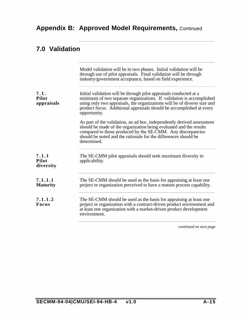
SECMM-94-04|CMU/SEI-94-HB-4 v1.0 A-15
Appendix B: Approved Model Requirements, Continued
7.0 Validation
Model validation will be in two phases. Initial validation will bethrough use of pilot appraisals. Final validation will be throughindustry/government acceptance, based on field experience.
7 . 1 .Pilotappraisals
Initial validation will be through pilot appraisals conducted at aminimum of two separate organizations. If validation is accomplishedusing only two appraisals, the organizations will be of diverse size andproduct focus. Additional appraisals should be accomplished at everyopportunity.
As part of the validation, an ad hoc, independently derived assessmentshould be made of the organization being evaluated and the resultscompared to those produced by the SE-CMM. Any discrepanciesshould be noted and the rationale for the differences should bedetermined.
7 . 1 . 1Pilotdiversity
The SE-CMM pilot appraisals should seek maximum diversity inapplicability.
7 . 1 . 1 . 1Maturity
The SE-CMM should be used as the basis for appraising at least oneproject or organization perceived to have a mature process capability.
7 . 1 . 1 . 2Focus
The SE-CMM should be used as the basis for appraising at least oneproject or organization with a contract-driven product environment andat least one organization with a market-driven product developmentenvironment.
continued on next page
A-16 SECMM-94-04|CMU/SEI-94-HB-4 v1.0
Appendix B: Approved Model Requirements, Continued
Derivation and Traceability of SE-CMM Requirements
Instruction The requirements herein contained were produced using materialgarnered from project participants as recorded in the documents listedbelow. A specific listing of author's meetings and copies of the minutesare available, upon request. Following the sources list is a traceabilitymatrix of SE-CMM requirements to the sections of the model thatgenerally cover the requirement.
Sources list 1. Minutes, Potential Project Participants Meeting, September 27, 19932. NCOSE Request for Information on Capability Assessments3. Minutes, SE-CMM Steering Group Meeting, January 27, 19944. Minutes, several SE-CMM Authors Meetings5. Minutes, October 10-12, 1994 Steering Group Meeting
continued on next page
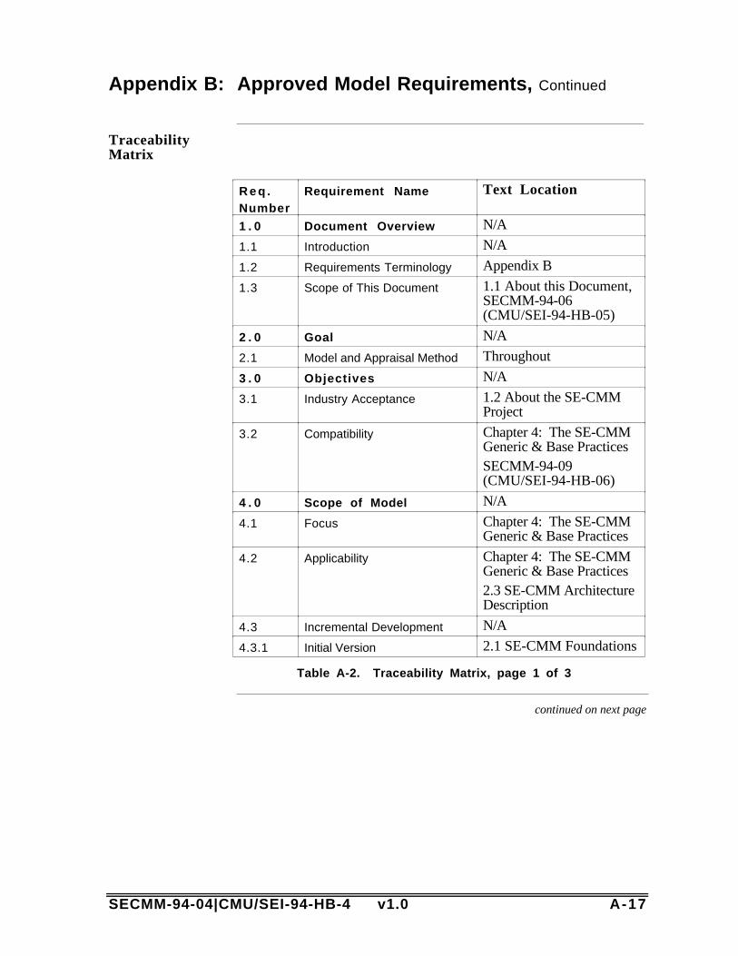
SECMM-94-04|CMU/SEI-94-HB-4 v1.0 A-17
Appendix B: Approved Model Requirements, Continued
TraceabilityMatrix
R e q .Number
Requirement Name Text Location
1 . 0 Document Overview N/A
1.1 Introduction N/A
1.2 Requirements Terminology Appendix B
1.3 Scope of This Document 1.1 About this Document,SECMM-94-06(CMU/SEI-94-HB-05)
2 . 0 Goal N/A
2.1 Model and Appraisal Method Throughout
3 . 0 Objectives N/A
3.1 Industry Acceptance 1.2 About the SE-CMMProject
3.2 Compatibility Chapter 4: The SE-CMMGeneric & Base PracticesSECMM-94-09(CMU/SEI-94-HB-06)
4 . 0 Scope of Model N/A
4.1 Focus Chapter 4: The SE-CMMGeneric & Base Practices
4.2 Applicability Chapter 4: The SE-CMMGeneric & Base Practices2.3 SE-CMM ArchitectureDescription
4.3 Incremental Development N/A
4.3.1 Initial Version 2.1 SE-CMM Foundations
Table A-2. Traceability Matrix, page 1 of 3
continued on next page
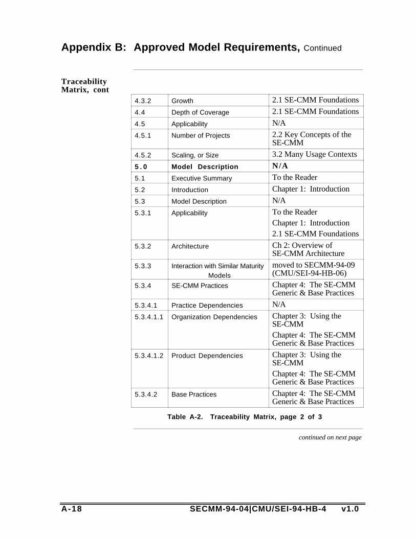
A-18 SECMM-94-04|CMU/SEI-94-HB-4 v1.0
Appendix B: Approved Model Requirements, Continued
TraceabilityMatrix, cont
4.3.2 Growth 2.1 SE-CMM Foundations
4.4 Depth of Coverage 2.1 SE-CMM Foundations
4.5 Applicability N/A
4.5.1 Number of Projects 2.2 Key Concepts of theSE-CMM
4.5.2 Scaling, or Size 3.2 Many Usage Contexts
5 . 0 Model Description N/A
5.1 Executive Summary To the Reader
5.2 Introduction Chapter 1: Introduction
5.3 Model Description N/A
5.3.1 Applicability To the ReaderChapter 1: Introduction2.1 SE-CMM Foundations
5.3.2 Architecture Ch 2: Overview ofSE-CMM Architecture
5.3.3 Interaction with Similar MaturityModels
moved to SECMM-94-09(CMU/SEI-94-HB-06)
5.3.4 SE-CMM Practices Chapter 4: The SE-CMMGeneric & Base Practices
5.3.4.1 Practice Dependencies N/A
5.3.4.1.1 Organization Dependencies Chapter 3: Using theSE-CMMChapter 4: The SE-CMMGeneric & Base Practices
5.3.4.1.2 Product Dependencies Chapter 3: Using theSE-CMMChapter 4: The SE-CMMGeneric & Base Practices
5.3.4.2 Base Practices Chapter 4: The SE-CMMGeneric & Base Practices
Table A-2. Traceability Matrix, page 2 of 3
continued on next page

SECMM-94-04|CMU/SEI-94-HB-4 v1.0 A-19
Appendix B: Approved Model Requirements, Continued
TraceabilityMatrix, cont
5.3.4.2.1 Usage/InterpretationGuidelines
Chapter 4: The SE-CMMGeneric & Base Practices
5.4 Glossary Appendix D: Glossary
5.5 Appendix Appendices A-C
6 . 0 Constraints N/A
6.1 Model Characteristics N/A
6.1.1 Management Characteristics 2.1 SE-CMM FoundationsChapter 4: The SE-CMMGeneric & Base Practices
6.1.2 Life Cycle Coverage 2.1 SE-CMM FoundationsChapter 4: The SE-CMMGeneric & Base Practices
6.1.3 Structure 2.3 SE-CMM ArchitectureDescriptionCh. 4: The SE-CMMGeneric & Base Practices
6.1.4 Functionality Chapter 4: The SE-CMMGeneric & Base Practices
6.2 Relationships to Other CMMs N/A
6.2.1 CMM for Software N/A
6.2.1.1 Terminology Whole document
6.2.1.2 Interfaces SECMM-94-09(CMU/SEI-94-HB-06)
7 . 0 Validation N/A
7.1 Pilot Appraisals See SE-CMM PilotAppraisal Report
7.1.1 Pilot Diversity See SE-CMM PilotAppraisal Report
7.1.1.1 Maturity See SE-CMM PilotAppraisal Report
7.1.1.2 Focus See SE-CMM PilotAppraisal Report
Table A-2. Traceability Matrix, page 3 of 3

A-20 SECMM-94-04|CMU/SEI-94-HB-4 v1.0

SECMM-94-04|CMU/SEI-94-HB-4 v1.0 A-21
Appendix C: References
Introduction This appendix provides the references for documents cited within theSE-CMM, as well as selected bibliographic sources for concepts.
ReferenceList
[AFMC] AF 800-Software Development Capability Evaluation(SDCE)
[FM 770-78] USALMC Army Field Manual, "SystemsEngineering," Training Support Center, Ft. Eustis(804-878-4668).
[IEEE 90] Dictionary of Computing Terms, IEEE 630-90,1990.
[IEEE 93] IEEE P1220. IEEE Standard for SystemsEngineering, Preliminary, 1993.
[MIL-STD-499B] Draft Systems Engineering Standard, AFMC, 1994.
[NCOSE 92a] National Council on Systems Engineering (NCOSE),Membership flier, 1992.
[NCOSE 92b] NCOSE. Introduction to NCOSE, 1992.
[NCOSE 93] NCOSE Capability Assessment Working Group(CAWG) Request for Information for SystemsEngineering Capability Maturity Models, 1993.
[Blanchard 81] Blanchard, Benjamin S.; & Fabrycky, Walter J.Systems Engineering and Analysis. EnglewoodCliffs, N.J.: Prentice-Hall, 1981.
[Charette 89] Charette, Robert N. Software Engineering, RiskAnalysis and Management. New York: IntertextPublications, McGraw-Hill, 1989.
[Chestnut 67] Chestnut, Harold. Systems Engineering Methods.New York, NY: John Wiley & Sons, 1967.
[Crab 93] Crab, Don. “The New PCs.” PC Magazine 12 (June15, 1993): 109-170.
continued on next page

A-22 SECMM-94-04|CMU/SEI-94-HB-4 v1.0
Appendix C: References, Continued
Referencel ist ,continued
[Defense 86] Defense Systems Management College. SystemsEngineering Management Guide. Washington, D.C.:U. S. Government Printing Office, 1986.
[Eisner 88] Eisner, Howard. Computer Aided SystemsEngineering. New Jersey: Prentice Hall, 1988.
[Foster 93] Foster, Kenneth R. “Math, Visualization, and DateAcquisition.” IEEE Spectrum 30 (November 1993):42-59.
[Hall 62] Hall, Arthur D. A Methodology for SystemsEngineering. Princeton, N.J.: Van NostrandCompany. 1962.
[Humphrey 87] Humphrey, Watts. Characterizing the SoftwareProcess Maturity of Contractors Preliminary Report,(CMU/SEI-87-TR-23, ADA 187230), Pittsburgh,PA: Software Engineering Institute, Carnegie MellonUniversity, September, 1987.
[Kornbluh 93] Kornbluh, Ken. “Seeing Data in Action, IEEESpectrum 30 (November 1993): 60-75.
[Lacy 92] Lacy, James A. Systems Engineering Management,Achieving Total Quality. New York: McGraw-Hill,Inc. 1992.
[Lano 90] Lano, R. J., “The N2 Chart,” System and SoftwareRequirements Engineering. Thayer, Richard &Dorfman, Merlin, eds. Washington: IEEE ComputerSociety Press, 1990: 244-271.
[McAuley 93] McAuley, James E.; & McCumber, William H. eds.Proceedings of the Third Annual InternationalSymposium of the National Council on SystemsEngineering. 1993.
[Miller 56] Miller, George. “The Magical Number Seven, Plusor Minus Two.” Psychological Review 63 (1956):81-97.
[Mish 86] Mish, Frederick C., ed. Webster’s Ninth NewCollegiate Dictionary. Springfield: Merriam-Webster.1986.
continued on next page

SECMM-94-04|CMU/SEI-94-HB-4 v1.0 A-23
Appendix C: References, Continued
Referencel ist ,continued
[O’Boyle 90] O’Boyle, Thomas F. “GE Refrigerator WoesIllustrate the Hazards in Changing a Product,” WallStreet Journal 1 (May 7, 1990).
[Paulk 91] Paulk, Mark, et. al. A Capability Maturity Model forSoftware, (CMU/SEI-91-TR-24, ADA 240603).Pittsburgh, PA: Software Engineering Institute,Carnegie Mellon University, August 1991.
[Paulk 93a] Paulk, Mark; Curtis, William; & Chrissis, MaryBeth. A Capability Maturity Model for Softwarev1.1, (CMU/SEI-93-TR-24, ADA 263403).Pittsburgh, PA: Software Engineering Institute,Carnegie Mellon University, February 1993.
[Paulk 93b] Paulk, Mark; Weber, Charles; Garcia, Suzanne;Bush, Marilyn; & Chrissis, Mary Beth. KeyPractices for the Capability Maturity Model forSoftware v1.1, (CMU/SEI-93-TR-25, ADA263432). Pittsburgh, PA: Software EngineeringInstitute, Carnegie Mellon University, February1993.
[Sage 77] Sage, Andrew P. Methodology for Large-ScaleSystems. New York: McGraw-Hill, 1977.
[Sailor 90] Sailor, J. Douglas. “System Engineering: AnIntroduction,” System and Software RequirementsEngineering. Thayer, Richard; & Dorfman, Merlin,eds. Washington: IEEE Computer Society Press,1990: 35-47.
[Schmidt 92] Schmidt, Stephen R.; & Launsby, Robert G.Understanding Industrial Designed Experiments.Colorado Springs, CO: Air Academy Press. 1992.
[Sedrick 91] Sedrick, Greg, ed. “A Commitment to Success,”Proceedings of the American Society for EngineeringManagement and the National Council on SystemsEngineering. NCOSE. 1991.
[Small 93] Small, Charles H. “Workstations vs PCs,” EDN 38(March 18, 1993):164-174.
continued on next page

A-24 SECMM-94-04|CMU/SEI-94-HB-4 v1.0
Appendix C: References, Continued
Referencel ist ,continued
[Weber 91] Weber, Charles, et al., Key Practices for theCapability Maturity Model for Software,(CMU/SEI-91-TR-25, ADA 2640604) Pittsburgh,PA: Software Engineering Institute, Carnegie MellonUniversity, August 1991.
[Wheelwright 92] Wheelwright, Steven C.; & Clark, Kim B.Revolutionizing Product Development: QuantumLeaps in Speed, Efficiency and Quality. New York:New York Press. 1992.
[Wood 91] Wood, David P. Extending Process ModelingAccuracy (CMU/SEI-91-SR-10) Pittsburgh, PA:Software Engineering Institute, Carnegie MellonUniversity, 1991.
[Wymore 76] Wymore, A. Wayne. Systems EngineeringMethodology for Interdisciplinary Teams. NewYork: John Wiley & Sons. 1976.
[Zajak 92] Zajak, Blair. “Enhanced System EngineeringEfficiency in the 21st Century,” Proceedings of theSecond Annual International Symposium of theNational Council on Systems Engineering.Morrison, Arthur F.; & Wirth, John M., eds,NCOSE, 1992.
SECMM-94-04|CMU/SEI-94-HB-4 v1.0 A-25
Appendix D: Systems Engineering Glossary
Introduction The following glossary has been prepared to be applicable to all SE-CMM work products. Therefore, some terms are defined which arenot, at present, included in this document. A common glossaryapproach was chosen because many terms used in the systemsengineering world look the same, but convey differing and sometimesconflicting meanings, depending on the background of the author andreader. By placing all the terms in a common location, in a commoncontext, we hope to facilitate reader understanding while promotingcontinuity across the product line.
These definitions are from sources chosen from a wide spectrum ofindustrial, government, and societal standards, modified only to theextent needed to place them in the SE-CMM context. The basic sourceof the information has been provided whenever possible.
Definitions with a reference of [SECMM] indicate definitions that wereproduced by the author team as part of the SE-CMM Project.

A-26 SECMM-94-04|CMU/SEI-94-HB-4 v1.0

SECMM-94-04|CMU/SEI-94-HB-4 v1.0
Issues Form for SECMM-94-04 Version 1.0
ReviewerInformation
Please provide your name and organizational affiliation.
Reviewer Name Reviewer Orgn Contact Phone #
If using hardcopy, you may attach several forms together with the nameon just the first one.
If using hardcopy, you may attach several forms together with the nameon just the first one.
IssueReference
Please list the page #(s) or other reference (e.g., "global," "Chapter 3,""Glossary") to which this issue applies. Attach the page for reference ifappropriate.
IssueStatement
Please characterize the issue as a problem (e.g., the glossary is notdetailed enough to support...) vs. a solution (e.g., add more detail to theglossary), so that the authors can understand the cause of the issue, notjust the suggested fix. Include your rationale for highlighting the issue,if appropriate.
Prioritization This issue is ________ out of my top 10 issues with the SE-CMMVersion 1.0.
ImpactAssessment
Please evaluate the impact the stated problem has on your use of the SE-CMM according to this scale:
____ High Impact: can't use model as intended w/out problem beingfixed.
____ Medium Impact: misleading or otherwise incorrect content ofsignificance to the reviewer.
____ Low Impact: content error of low significance to reviewer.
Note:editorialissues
For typographical/grammatical/punctuation edits, please forward theredlined pages without the issue form attachment.