a thermo-mechanical model for sfrc beams or slabs at
TRANSCRIPT

ORIGINAL ARTICLE
A thermo-mechanical model for SFRC beams or slabsat elevated temperatures
Peter Heek . Jasmin Tkocz . Peter Mark
Received: 23 January 2018 / Accepted: 16 June 2018 / Published online: 21 June 2018
Abstract The bearing capacity of steel fibre rein-
forced concrete (SFRC) at elevated temperatures is the
subject of significant ongoing research, as the effect of
steel fibres on concrete performance at higher tem-
peratures is poorly understood. On one hand, steel
fibres increase the average thermal conductivity of the
concrete cross section and lead to greater heating
within a concrete structural member during fire
exposure, and on the other, fibres reduce crack widths
and prevent excessive spalling. The former effect
negatively impacts SFRC performance at high tem-
perature, whereas the latter effect protects the inner
structure from direct fire exposure. Additionally, the
decreasing strength of steel at higher temperatures can
result in the sudden failure of fibre or traditionally
reinforced concrete. Within this contribution, a cou-
pled thermo-mechanical model is developed in order
to investigate the influence of steel fibres on the
thermal loading of concrete. The effect of fibres on
heat transmission within concrete, the length of time
for which concrete can sustain thermal loads, and on
the bending stiffness of reinforced concrete beams or
slabs is investigated. The heat transfer process is
modelled using Fourier’s partial differential equation
of transient heat conduction. A modified plastic hinge
model and moment–curvature relations are used to
describe stress-dependent deformations. Thus, two
alternative approaches are used to adequately track the
localisation of damage for single cracks and for
distributed and multiple cracking. Thermo-mechani-
cal coupling is achieved by means of temperature-
dependent stress–strain relations. These are derived
for SFRC based on experimental data from the
literature. Experiments are performed in which con-
crete slabs reinforced with variable amounts of fibres
and rebar are exposed to combined thermal and
mechanical loadings. The results of these experiments
are used to validate the proposed model. Themeasured
and predicted results agree well and indicate that steel
fibres have a positive effect on the fire resistance of
structures, assuming additional rebar is provided to
prevent crack localisation. Additionally, it is shown
that temperature fields within concrete remain almost
unaffected by variations in fibre content.
Keywords Thermo-mechanical modelling � Heattransfer � Thermal effects � Fire resistance duration �Moment–curvature relation � Plastic hinge model �Fibre reinforced concrete � Large-scale tests
P. Heek � J. Tkocz (&) � P. Mark
Institute of Concrete Structures, Ruhr-University
Bochum, Universitatsstraße 150, 44780 Bochum,
Germany
e-mail: [email protected]
P. Heek
e-mail: [email protected]
P. Mark
e-mail: [email protected]
Materials and Structures (2018) 51:87
https://doi.org/10.1617/s11527-018-1218-8(0123456789().,-volV)(0123456789().,-volV)
� The Author(s) 2019, corrected publication April 2019
The original version of this article was revised due to a
retrospective Open Access order.

List of symbols
a Thermal diffusivity
A Cross-sectional area
cnom Concrete cover
cp Specific heat capacity
df Fibre diameter
e, E Spacing of loading, modulus of
elasticity
fc, ft, f1f , f2
f Strength (compressive concrete
strength, tensile concrete strength, and
post-cracking tensile strengths of
SFRC corresponding to predefined
strains e1 and e2, respectively)F Force
g, i, j, k, n, r Counter variables
I Moment of inertia
ktf Ratio of SFRC’s post-cracking tensile
strength at elevated temperatures to
that at normal temperature
l, lch, lf Length, characteristic length, fibre
length
m, M, �M Mass, bending moment, virtual
bending moment
q, Q Heat flux density, heat flow volume
R Fire resistance duration in minutes
si, li,k Element sizes (element length in
direction of the heat flow, contact
length between two adjacent elements
i and k perpendicular to the heat flow)
s Width of a plastic hinge
SLS Serviceability limit state
t, T Time, absolute temperature
ULS Ultimate limit state
Vf Fibre volume content
w Crack width
x, x, y ,z Vector of a spatial location, spatial
coordinates (Cartesian)
aK, aT Fictive heat-transfer coefficient,
thermal expansion coefficient
d, dth, dr Deflections (overall, thermic and
stress-dependent)
e, ec,top, ec,bot,es1
Strains (overall, concrete strains at the
top or bottom of a section, rebar
strain)
ef, em Emission coefficients (fumes and
solid)
h, h0, hr Radiation temperature (overall,
initial), rotation angle
#, #0, #m,
D#, #ID
Temperature (basic, initial, average,
difference, equivalent)
j Curvature
k Thermal conductivity
q Density
r, rc, rt, rs1 Stress (general, concrete in
compression and tension, in
longitudinal rebar)
rSB Stefan–Boltzmann constant
u, uel, upl Rotation angle (overall, elastic and
plastic portions)
1 Introduction
Steel fibre reinforced concrete (SFRC) is widely used
in civil engineering as it considerably enhances the
reliability of reinforced concrete structures. Although
many different fibre types are available, mechanically
anchored steel macro fibres have been proven to be
especially suitable for retarding crack growth in
concrete after crack formation. The governing param-
eters that influence the post-cracking tensile strength
of SFRC are fibre type, dosage, orientation and the
fibre-concrete bond conditions [1, 2]. At subcritical
fibre contents, SFRC exhibits a softening material
response after cracking. Low-fibre-content reinforce-
ment is therefore often used in conjunction with
traditional rebar to ensure the structural integrity of
reinforced concrete members on a cross sectional
level. In contrast, supercritical fibre contents induce
material stiffening after concrete cracking.
In common ultimate limit state (ULS) design [3],
the necessary rebar reinforcement ratios can be
significantly reduced if steel fibres are also included
as a component of the reinforcement scheme [4, 5].
However, in the case of fire resistant design, the post-
cracking tensile strength of SFRC is not taken into
account by any current or pre-normative standard [6].
It is conservatively assumed that only rebar carries
tensile loads at elevated temperatures. This leads to
difficulties in determining the necessary residual
bearing capacity of a reinforced concrete member
[7], as the contribution of the fibres to the strength of
the remaining cross-section after loading is neglected.
Significant strength reserves may therefore be over-
looked in the standard design process. The thermal
87 Page 2 of 16 Materials and Structures (2018) 51:87

conductivity and the temperature-variant stress–strain
response of SFRC are therefore an object of interest in
current SFRC research [8–16].
The impact of fibres on heat transmission is a
controversial subject among experts. Various sources
report that the presence of steel fibres accelerates
heating rates within concrete [17], whereas other
sources claim that fibres retard the heating process
[18]. The enhanced conductivity of steel compared to
that of concrete may result in varying temperature
distributions within the composite material, which
may lead to local damage within a given cross
section. Conversely, if cracks develop within a
concrete member during heating, steel fibres prevent
excessive concrete spalling and thus protect the inner
structure from direct damage under sustained fire
exposure. This protective effect is, however, only
present as long as the heated fibres are able to
sufficiently transfer tensile forces across a crack. If the
fibres themselves are heated to such an extent that their
tensile strength becomes negligible, the fibres cannot
fulfil their intended purpose.
In order to predict SFRC behaviour under thermal
loading, it is essential to properly analyse the interac-
tion between the thermal and mechanical behaviour of
the material. Within this contribution, a coupled
thermo-mechanical model for SFRC is presented.
The model is used to investigate both the heat
propagation as a function of the fibres’ volume
contents and the overall load-bearing capacity of
SFRCmembers subjected to bending while exposed to
fire. Effects of local concrete spalling or time-depen-
dent behaviour, such as creep or viscosity changes, are
not considered explicitly. Large-scale fire tests con-
ducted on concrete slabs reinforced with both steel
fibres and traditional reinforcement are used to verify
the results. The tested slabs are heated according to a
uniform temperature time curve according to Euro-
code 1-1-2 [19].
2 Modelling the thermo-mechanical behaviour
The weakly coupled model is derived in three steps. At
first, the equation of heat transfer in solid bodies is
presented. Second, the bending behaviour of SFRC
elements with or without rebar under mechanical
loadings is introduced and third, the two strain fields
are coupled by overlapping portions and introducing
temperature-dependent stress–strain laws. Since
stress–states are assumed not to influence heat trans-
mission, the heat flux is derived a priori. Throughout,
damage induced material loss due to spalling is
neglected so that the initial geometry is preserved.
2.1 Heat transmission
The model is based upon the principles of continuous
composite body heat transmission. For the sake of
simplicity, fire exposure or down-cooling to ambient
conditions are assumed to occur at the outer bound-
aries from convective and radiative portions only
while inner heat sources are generally neglected.
The temperature field #(x,t) in the solid depends on
the spatial location x and time t, which changes
progressively due to temperature exposure and the
corresponding temperature gradients entailing a heat
flow in the gradient’s direction. Considering heat
balance in an incremental volume element Fourier’s
partial differential equation of transient heat transmis-
sion [20, 21] yields:
o#ðx; tÞot
� ar2#ðx; tÞ ¼ 0: ð1Þ
The solid is assumed to be homogeneous and
isotropic, which also holds true for any arbitrary,
infinitesimal volume therein. Consequently, the ther-
mal diffusivity a simplifies to a scalar, denoted by
a ¼ k=ðq cpÞ, the ratio of the thermal conductivity k tothe product of material density q and specific heat
capacity cp.
The heat flow volume Q [J] of a solid is computed
from its mass m, its specific heat capacity and
temperature T [K] relative to absolute zero at
0 K = - 273.15 �C.
Q ¼ m cp T ð2Þ
Two volume fractions with a contact area A
exchange heat flow volume increments dQ per time
increment dt, which is described by the heat flux
density _q.
_q ¼ dQ
A dt¼ � kr#ðx; tÞ ð3Þ
Since heat flux and the field of temperature
gradients are proportionally coupled, Cartesian com-
ponents can be derived in the three spatial directions x,
y and z.
Materials and Structures (2018) 51:87 Page 3 of 16 87

_qx ¼ � ko#
ox; _qy ¼ � k
o#
oy; _qz ¼ � k
o#
oz: ð4Þ
Separation into x, y and z components benefits
the numerical solution of heat transfer by discretis-
ing space and time domains [22, 23] using
consistent rectangular volume elements and time
steps Dt, respectively. Figure 1 illustrates such a
spatial discretisation of a reinforced beam with
boundary contact elements simulating ambient or
fire conditions. The arrangement is chosen to
effectively derive transient temperature propagation
in spreadsheet environments [24–27]. Material ele-
ments are idealised by specific cells in the spread-
sheet surrounded by others to model boundary
conditions of convection and radiation.
Starting with an initial temperature field #(x,t) at a
time t, the current distribution at the end of a time step
t ? Dt is obtained by explicit time integration. Tem-
peratures are assumed to remain stepwise constant in
Dt while the heat flow changes. For convenience
derivations are restricted to two-dimensional cases in
the remainder.
Cross-sections are discretised by rectangular ele-
ments. Each element i is characterised by an associ-
ated area Ai = xi zi, its average temperature #i at a time
t and its thermal diffusivity ai. Internal elements are
surrounded by g = 4 solid elements. By contrast,
boundary elements exhibit one or two free surfaces (r)
that reduce the number of the inner surfaces to
g = 4 - r. An alteration of heat flow volume (DQi/
Dt) results from the sum of up to four densities _qi alongthe inner or boundary contact lengths li,j and li,r.
DQi
Dt¼
Xg
j¼1
_qi;j li;j þX4�g
r¼1
_qi;r li;r ð5Þ
Thereby, the directed heat flow density between
two differently heated internal elements i and k
depends on the element lengths si, sk, the thermal
conductivities ki, kk and the temperature difference
between #i and #k.
_qi;k ¼2ki kk
kk si þ ki sk#k � #ið Þ ð6Þ
Boundary conditions, i.e. heat sources or cooling at
the surfaces, are treated similarly. For this purpose the
corresponding component is replaced by a fictitious
transfer quantity from or to the outside of the body.
_qi;r ¼2ki aK;i
aK;i si þ 2ki#ID;i � #i
� �ð7Þ
Convective and radiative portions are modelled by
an equivalent temperature #ID depending on a ficti-
tious heat-transfer coefficient aK [28] and the surface
temperature #0 [22, 29].
#ID ¼ #0 þ1
aK_q0 ¼ #0 þ
1
aKaKð#A � #0Þ þ _qrad½ �
ð8Þ
In case of fire exposure, the radiative heat flow _qradbecomes a function of the grey body emission
coefficients of the solid em and the surrounding fumes
ef [21]. rSB denotes the Boltzmann constant.
_qrad ¼ ef em rSB ð#A þ 273:15Þ4 � ð#0 þ 273:15Þ4h i
ð9Þ
The radiation temperature #A and the surface
temperature #0 are both related to absolute zero. For
the sake of simplicity, #A can be set to the discharge
temperature of the fumes, #A = h [28] and #0 to the
corresponding element’s one #0 = #i. Hence, the
temperature field at the end of a time step reads:
#tþDti ¼ #t
i þ1
cp;ið#Þ qið#Þ xi ziDQi
DtDt: ð10Þ
PC/SFRC rebar air heating
qi,4
qi,1
qi,2
qi,3
4
3
2
1
i
boundary elementinternal element
qi,r
qi,1
qi,2
qi,3
3
2
1
i
l i,2
li,1
s2
s 1
xizi li,r
xz
NA
Fig. 1 Discretised solid body with boundary conditions (bot-
tom) and heat flux in internal and boundary elements (top)
87 Page 4 of 16 Materials and Structures (2018) 51:87
To ensure numerical stability the time step size Dt[22, 23] has to be limited. For two-dimensional cases it
depends on thermal parameters (cp, q, k) and element
sizes (xi, zi):
Dt� cp;i qi2ki
x2i z2i
x2i þ z2i: ð11Þ
To reduce the computational demand the check
might be restricted to the smallest element of a
discretisation.
2.2 SFRC beams or slabs under mechanical
loading
Elevated temperatures considerably affect the
mechanical material response of plain concrete (PC),
SFRC and steel rebar. Stresses are a function of strains
and both depend on temperature. Introducing a
separation of strains into thermal (superscript th) and
purely stress-dependent (superscript r) portions
according to [7] gives:
e ¼ eth þ er ¼ aT D#þ er: ð12Þ
Thus, mechanical and thermal analyses can be
conducted independently.
A softening material effect due to elevated temper-
atures can be considered in mechanical analyses only. In
this case eth purely arises from temperature differences
D# and the coefficients of thermal expansion aT(#).Mechanical modelling considers bendingmomentsM
andaxial forcesNonly, shear deformations are neglected.
On cross-sectional level strains are distributed linearly
over the cross-section’s height h. Moreover, the bond
between concrete and rebar is assumed perfect and slip
free. Uniaxial stress–strain laws describe the mechanical
response of PC, SFRC and rebar which depend on the
current temperature of the material and thus change with
time. Applying equilibrium conditions for a two dimen-
sional case yields:
N ¼ZZ
A
r dA ~¼ZZ
A
rc dAþXn
i¼1
Asi rsi ð13Þ
M ¼ZZ
A
r z dA ~¼ZZ
A
rc z dAþXn
i¼1
Asi zi rsi
ð14Þ
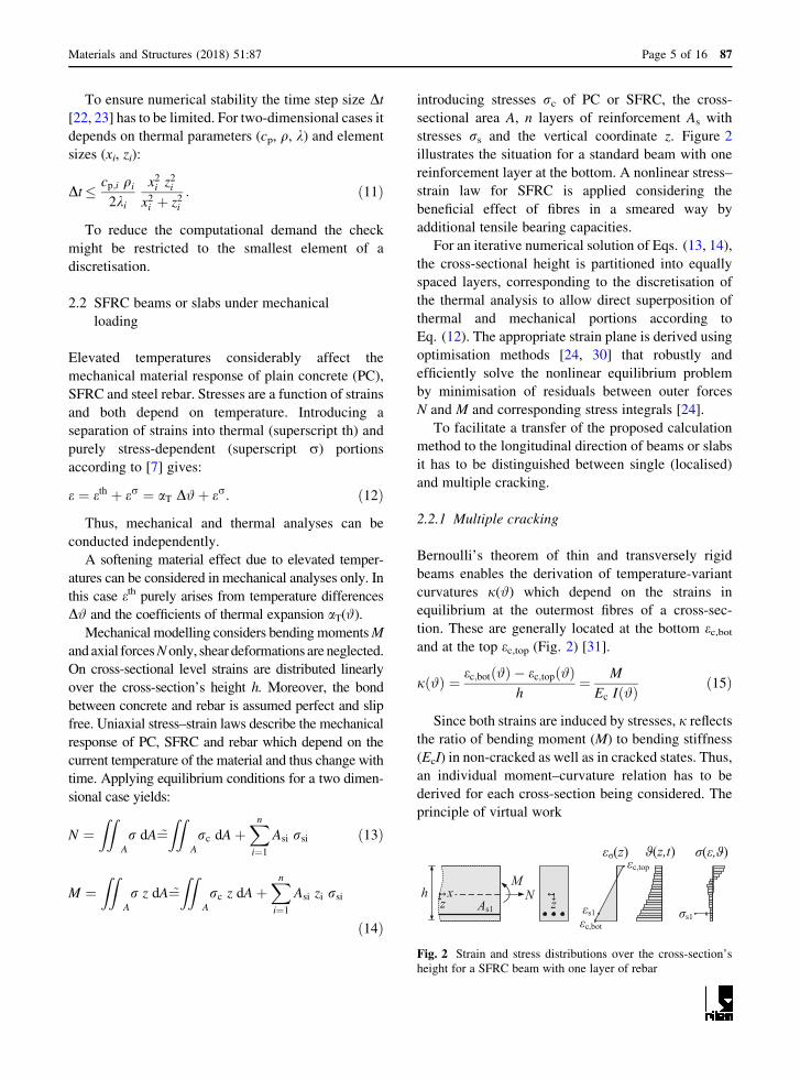
introducing stresses rc of PC or SFRC, the cross-
sectional area A, n layers of reinforcement As with
stresses rs and the vertical coordinate z. Figure 2
illustrates the situation for a standard beam with one
reinforcement layer at the bottom. A nonlinear stress–
strain law for SFRC is applied considering the
beneficial effect of fibres in a smeared way by
additional tensile bearing capacities.
For an iterative numerical solution of Eqs. (13, 14),
the cross-sectional height is partitioned into equally
spaced layers, corresponding to the discretisation of
the thermal analysis to allow direct superposition of
thermal and mechanical portions according to
Eq. (12). The appropriate strain plane is derived using
optimisation methods [24, 30] that robustly and
efficiently solve the nonlinear equilibrium problem
by minimisation of residuals between outer forces
N and M and corresponding stress integrals [24].
To facilitate a transfer of the proposed calculation
method to the longitudinal direction of beams or slabs
it has to be distinguished between single (localised)
and multiple cracking.
2.2.1 Multiple cracking
Bernoulli’s theorem of thin and transversely rigid
beams enables the derivation of temperature-variant
curvatures j(#) which depend on the strains in
equilibrium at the outermost fibres of a cross-sec-
tion. These are generally located at the bottom ec,botand at the top ec,top (Fig. 2) [31].
jð#Þ ¼ ec;botð#Þ � ec;topð#Þh
¼ M
Ec Ið#Þð15Þ
Since both strains are induced by stresses, j reflects
the ratio of bending moment (M) to bending stiffness
(EcI) in non-cracked as well as in cracked states. Thus,
an individual moment–curvature relation has to be
derived for each cross-section being considered. The
principle of virtual work
M
As1
h Ns1
c,bot
c,top
s1
(z,t)(z) ( , )
zx
z
Fig. 2 Strain and stress distributions over the cross-section’s
height for a SFRC beam with one layer of rebar
Materials and Structures (2018) 51:87 Page 5 of 16 87

dðxÞ ¼Z l
0
jðxÞ �MðxÞ dx ð16Þ
and Simpson’s rule are employed to numerically
integrate the curvature j(x) and the virtual bending
moment �MðxÞ along x resulting in the vertical
deflections d(x). Of course, a suited number of
integration points along the length l has to be provided
to adequately cover stiffness reductions due to crack-
ing. Furthermore, tension stiffening might be approx-
imated by modified stress–strain relations of rebar [5].
2.2.2 Localisation due to single cracking
The softening post-cracking response of SFRC beams
containing subcritical amounts of steel fibres but no
additional rebar causes a localisation of deflections at
single cracks [2, 3, 32]. Within the fracture process
zone a discontinuity, often denoted a plastic hinge,
forms that governs the beam’s deflections by its
rotation. Rotation depends on the strain distribution in
the region that develops nonlinearly over the width of
the hinge. To transfer localisation to a quasi-contin-
uous approach, Strack [33] developed a plastic hinge
model. It is based on average strains of the tensile and
compressive fibres in the discontinuity region, while
equilibrium is checked at the cracked cross-section
only, Fig. 3. In this regard, uniaxial material functions
by means of stress–crack–width relations r(w) accord-ing to [32, 33] are transferred to stress–strain ones r(e)and vice versa introducing a characteristic length lchaccording to the notion of a crack band [34]. Assuming
linear elastic stress–strain behaviour in the non-
cracked state, the post cracking strains consist of
elastic (eel) and plastic (epl) portions:
e ¼ eel þ epl ¼rEc
þ w
lch: ð17Þ
In case of common macro fibres the characteristic
length lch corresponds to about twice the fibre’s length
and thus to an almost constant value. Subsequently, lchis set equal to 140 mm based on [2]. This value
approximately refers to fibre lengths of 50–80 mm
and—at least for thin structures in bending—resem-
bles lch & h, as advised in [3].
Strack’s plastic hinge model was originally pro-
posed for SFRC subjected to short term loadings at
normal temperatures [33], but allows for generalisa-
tions in case of fatigue [35] or elevated temperatures.
Elevated temperature requires customisation of the
material behaviour only. Moreover, the calculation
procedure is more reliable when load instead of
deformation controlled. While the geometry of the
beam, its loading pattern and temperature-dependent
material behaviour are prescribed for each discrete
time step, the strains at the border of the hinge are
iteratively computed. Subsequently, the basic model is
F/2 F/2
plastic hinge
s = 2h
e > 0
lbending moments
deflections:
+
pl
el
el
pl
M
w
h
xsneutral axis
w
t,cr = ft / Ec
c,top
c,botncr
s = 2hc,bot
c,top
M(F,e)
(w)
()
c,max
ncr
Fig. 3 Basic parameters of Strack’s plastic hinge model [33], left: structural system as well as geometry and deflection characteristics;
right: strain and stress distributions
87 Page 6 of 16 Materials and Structures (2018) 51:87
briefly summarised in its key aspects respecting
temperature dependencies and axial forces for the
sake of simplicity.
Presuming a stress distribution at 45� from the
compressed to the tensile edge, the longitudinal extent
of the plastic hinge equals about twice the cross-
section’s height, s = 2 h [33]. In non-cracked regions
(subscript ncr), strains encr are obtained based on linearelastic theory.
encr ¼M
Wncr Ec
ð18Þ
Here,Wncr denotes the sectional bending resistance
and M the bending moment, which can be induced by
three (e = 0) or four-point (e[ 0) bending from the
force F. Average tensile (�ec; bot) and compressive
(�ec; top) strains at the edges describe the hinge’s overalldeformation. They depend on the deflections in
equilibrium and result from the tensile and the
compressive zone of the cracked cross-section, respec-
tively. Within the tensile zone an artificial strain
�ec;bot ¼ �eel þ �ew is introduced by summing up average
elastic strains (�eel) and the maximum crack width w
smeared over the hinge’s width [33]. Thereby, a linear
crack opening over the cross-section’s height is
assumed.
�eel ¼1
2h
Zh
�h
ec;bot dxs ¼1
2het;max ðhþ e=2Þ�
þencr ðh� e=2Þ� ð19Þ
et;max ¼M
Wncr Ec
� et;cr ¼ft
Ec
ð20Þ
�ew ¼ w
sð21Þ
Cracking occurs if the induced strains exceed et,cr,which equals the ratio of concrete’s tensile strength ftto its Young’s modulus Ec. The average compressive
strains follow iteratively considering the height of the
compressive zone xc = n h and exhibit a distinct
nonlinear course as indicated by ec,top [33] in Fig. 3.
�ec;top ¼1
2h
Zh
�h
ec;top dxs ¼ encr � ðencr
� ec;maxÞ arctanð1=gÞ ðg3 þ gÞ � g2� �
ð22Þ
with: ec;max ¼ encr � encr��ec;toparctanð1=gÞ ðg3þgÞ�g2 and
g ¼ 2n ¼ �ec;topj j�ec;bot
.
The hinge’s overall rotation hr consists of elastic
(subscript el) and plastic (subscript pl) portions arising
from the average strains.
hr ¼ hr;el þ hr;pl ¼ 2/ ¼ 2ð�ec;bot � �ec;topÞ ð23Þ
The same characteristic applies to the correspond-
ing deflections d that are superimposed analogously.
d ¼ del þ dpl ð24Þ
with
del ¼F K ðl� eÞ
48Ec I3l2 � 4
l� e
2
� �2" #
;
K ¼ 1; e ¼ 0
2; e[ 0
� ð25Þ
and
dpl ¼ hr;pll
4¼ 2 �ec;bot � �ec;top � 2 �eelj j
� � l
4
¼ w
1� nð Þ hl
4: ð26Þ
Therein, I denotes the geometrical moment of inertia
of the non-cracked cross-section and l the total length
of an assumed beam section.
2.3 Coupling
Thermo-mechanical coupling is achieved via temper-
ature-dependent stress–strain relations. Starting from
initial conditions with a constant temperature state in
the solid (e.g. #0 = 20 �C at t = t0) the temperature
distribution at the end of a time step t ? Dt followsaccording to Sect. 2.1. It affects the stress–strain
relations in each lamella of the discretised body and
thus governs sectional equilibrium (Sect. 2.2). Since
material’s stiffness and strength decrease progres-
sively with increasing temperature, strains have to
increase to ensure equilibrium of forces. If equilibrium
cannot be achieved anymore, the structure fails.
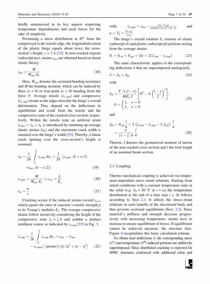
Figure 4 recapitulates this basic calculation scheme.
To obtain total deflections d, the corresponding stress
(dr) and temperature (dth) induced portions are additivelysuperimposed. Since distributed cracking is expected for
SFRC structures reinforced with additional rebar and
Materials and Structures (2018) 51:87 Page 7 of 16 87
Eq. (16) serves to derive dr, it must be replaced by
Eq. (24) in case of single localised cracking.
dth depends on the thermal strains eth, which usuallyturn out highly nonlinear distributed over the height
with maxima on the heated face. Since eth equals to theproduct of temperature difference and thermal expan-
sion coefficient—Eq. (12)—the temperature gradient
can be calculated instead to obtain dth. For conve-
nience, the temperature field over the cross section’s
height is partitioned into constant, linear and residual
nonlinear parts [36]. Only the linear part—the tem-
perature gradient D#—causes vertical deflections. The
others induce axial deformations or constraints. The
gradient D# reads
D# ¼ h
I
Z
A
#ðzÞ z dA ð27Þ
or when discretised with i = 1 to m lamellae Ai over
the cross-section’s height
D# ¼ h
I
Xm
i¼1
#i zi Ai: ð28Þ
Employing the principle of virtual work, thermal
deflections are obtained integrating the product of
thermal curvatures jth = (aT D#)/h and a virtual
bending moment �MðxÞ along the effectively heated
length leff,h of a specimen [31].
dthðxÞ ¼Zleff;h
0
�MðxÞ jthð#Þ dx
¼Zleff;h
0
�MðxÞ aTð#Þ D#h
dx ð29Þ
2.4 Material response and properties at elevated
temperatures
In general, analysis relies on well-established material
equations and parameters from literature
[7, 21, 22, 28, 37] when available. Table 1 summarises
material parameters for PC and rebar and lists general
thermal characteristics while reference to relevant
literature sources is made. Beyond that, new
approaches are proposed to model SFRC’s effective
conductivity and its softening behaviour as a function
of temperature.
2.4.1 Thermal parameters of SFRC
The conductivity of SFRC kSFRC is proposed to be
computed from a weighted average of volumes of
concrete and steel. Thus, a homogenous composite is
assumed which holds true, if the representative length
of specimens and discretisation considerably exceeds
the internal lengths of fibres and aggregates. Intro-
ducing the fibre volume content Vf and the conduc-
tivities kc and ks of concrete and steel, kSFRC reads:
kSFRCð#Þ ¼ Vf ksð#Þ þ ½1� Vf � kcð#Þ: ð30Þ
While literature on the rule of mixture is generally
ample (e.g. [8, 38, 39]), an increased fibre volume
content Vf in Eq. (30) yields enhanced conductivities
and vice versa. By contrast, the fibre’s impact on
concrete’s density, specific heat capacity and heat-
transfer as well as thermal expansion coefficients, is
considered subordinate [40] and thus neglected. Pure
concrete characteristics are assumed.
2.4.2 Stress–strain relations of SFRC
Temperature-dependent stress–strain relations of con-
crete in compression [7] are adopted for SFRC, too,
since they do not remarkably differ up to the softening
branch [10] as it is with normal temperatures [1–3]. By
initial conditionst= t0, 0
heat transfert+ t
time incrementt+ t
material response( , t+ ) ( , t)
displacementst+ = th,t+ + ,t+
yes
sectional equilibriumN= 0, M= 0fracture
no
Fig. 4 Flow chart of the calculation scheme of the coupled
thermo-mechanical model
87 Page 8 of 16 Materials and Structures (2018) 51:87

contrast, a more specific behaviour is proposed in
tension. The discrete crack-bridging ability of fibres in
fire is captured in a smeared way introducing a
multilinear stress–strain relation rt(et,#). Based on thematerial response at a reference temperature of
# = 20 �C, softening with increasing temperatures is
modelled by a global, multiplicative softening param-
eter ktf(#). It represents the ratio of concrete’s degraded
to initial strength and is defined in the range of 0–1. To
assess the temperature-dependent stiffness a temper-
ature-variant Young’s modulus of concrete Ec(#) is
adopted [7]. It represents an artificial numerical value
to also integrate the effects of high-temperature
creeping [36].
rtðet; #Þ ¼
Ecð#Þ et; 0� et �ft k
ft ð#Þ
Ecð#Þ
f f1 kft ð#Þ;ft k
ft ð#Þ
Ecð#Þ\et � e1
f f1 kft ð#Þ þ et � e1e2 � e1
f f2 � f f1� �
kft ð#Þ; e1\et � e2
8>>>>>><
>>>>>>:
ð31Þ
Linear-elastic behaviour is assumed up to the
tensile strength ft. A bilinear function is used to model
the fibre’s post-cracking bearing capacity employing
two residual strength values f1f and f2
f at fixed strains e1and e2, respectively. The concept of two strain values
with associated strengths is chosen to comply with the
established procedure of material classifications via
standard bending tests in [1–3]. The strains e1 = 3.5%and e2 = 25% correspond to crack widths of
w1 & 0.45 mm and w2 & 3.15 mm employing lch-= 140 mm according to [2]. While the strength at w1
is associated with the serviceability limit state (SLS),
the strength at w2 corresponds to ULS conditions
[1, 4].
The definition of temperature-invariant, constant
strain values e1 and e2 in Eq. (31) leads to a conser-
vative underestimation since [7, 37] report on enlarged
strain boundaries for PC and rebar under sustained fire
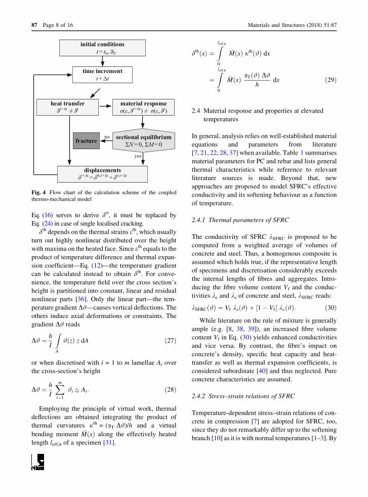
exposure. Figure 5 illustrates the derived stress–strain
relations in tension and compression. It should be
noted that discontinuity in the plotted temperature-
dependent stress–strain curves is virtually due to
intended cuts in the strain scales highlighted by dash-
dotted lines.
Table 1 Basic thermal parameters and corresponding literature sources
Parameter Denotation Value/source
a(#) Diffusivity a = k/(q cp)
k(#) Conductivity
Concrete Lower limit acc. to EC 2-1-2, 3.3.3 (2), [7]
Steel EC 3-1-2, 3.4.1.3 (1), [37]
q(#) Density
Concrete EC 2-1-2, 3.3.2 (3), [7]
Steel EC 3-1-2, 3.2.2 (1), [37]
cp(#) Specific heat capacity
Concrete EC 2-1-2, 3.3.2 (1), [7]
Steel EC 3-1-2, 3.4.1.2 (1), [37]
em Emission coefficient concrete 0.7 acc. to [21, 22]
ef Emission coefficient fumes 1.0, [21, 22]
rSB [W/(m2 K4)] Boltzmann constant 5.67 9 10-8, [21, 22]
aK (W/m2 K) Fictive heat-transfer coefficient [28]
Non temperature-exposed concrete surface 4
To consider radiative portions at the non
temperature-exposed concrete surface
9
Temperature-exposed concrete surface 25
aT(#) Thermal expansion coefficient aT = eth/D#
Concrete Acc. to EC 2-1-2, 3.3.1 (1), [7]
Steel Acc. to EC 2-1-2, 3.4 (1), [7]
Materials and Structures (2018) 51:87 Page 9 of 16 87
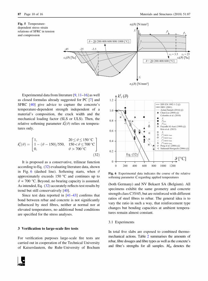
Experimental data from literature [9, 11–16] as well
as closed formulas already suggested for PC [7] and
SFRC [40] give advice to capture the concrete’s
temperature-dependent strength independent of a
material’s composition, the crack width and the
mechanical loading factor (SLS or ULS). Then, the
relative softening parameter ktf(#) relies on tempera-
tures only.
kft ð#Þ ¼1; 20�#� 150 �C1� ð#� 150Þ=550; 150\#� 700 �C0; #[ 700 �C
24
35
ð32Þ
It is proposed as a conservative, trilinear function
according to Eq. (32) evaluating literature data, shown
in Fig. 6 (dashed line). Softening starts, when #
approximately exceeds 150 �C and continues up to
# = 700 �C. Beyond, no bearing capacity is assumed.
As intended, Eq. (32) accurately reflects test results by
trend but still conservatively [40].
Since test data reported in [41–43] confirms that
bond between rebar and concrete is not significantly
influenced by steel fibres, neither at normal nor at
elevated temperatures, no additional bond conditions
are specified for the stress analyses.
3 Verification to large-scale fire tests
For verification purposes large-scale fire tests are
carried out in cooperation of the Technical University
of Kaiserslautern, the Ruhr-University of Bochum
(both Germany) and NV Bekaert SA (Belgium). All
specimens exhibit the same geometry and concrete
strength class C35/45, but are reinforced with different
ratios of steel fibres to rebar. The general idea is to
vary the ratio in such a way, that reinforcement type
changes but bending capacities at ambient tempera-
tures remain almost constant.
3.1 Experiments
In total five slabs are exposed to combined thermo-
mechanical actions. Table 2 summarises the amounts of
rebar, fibre dosages and fibre types as well as the concrete’s
and fibre’s strengths for all samples. Mt0 denotes the
c( ) [‰]
c( ) [N/mm²]
t( ) [N/mm²]
t( ) [‰] 1 = 3.5
-3.5-25-45
ff1 ff2
= 20/200/400/600/800/1000 [°C]
ft
fc
= 20/200/400/600 [°C]
2 = 25
Fig. 5 Temperature-
dependent stress–strain
relations of SFRC in tension
and compression
1000 120080060040020000
0.2
0.4
0.6
0.8
1.0
1.2
[°C]
kft ( )
DIN EN 1992-1-2 (ft) DBV (2001)Aslani/Samali (2014) (ft) Chen/Liu (2004) (ft) Colombo et al. (2010) ftf fSLSf f
ULSFaiyadh/Al-Ausi (1989) (ft) Kim et al. (2015) ftf f
CMOD=1mmf f
CMOD=2mmf f
CMOD=3mmf f
CMOD=5mmPeng et al. (2006) (ft) Suhaendi/Horiguchi (2006) (ft)
Eq. (32)
Fig. 6 Experimental data indicates the course of the relative
softening parameter ktf regarding applied temperatures
87 Page 10 of 16 Materials and Structures (2018) 51:87
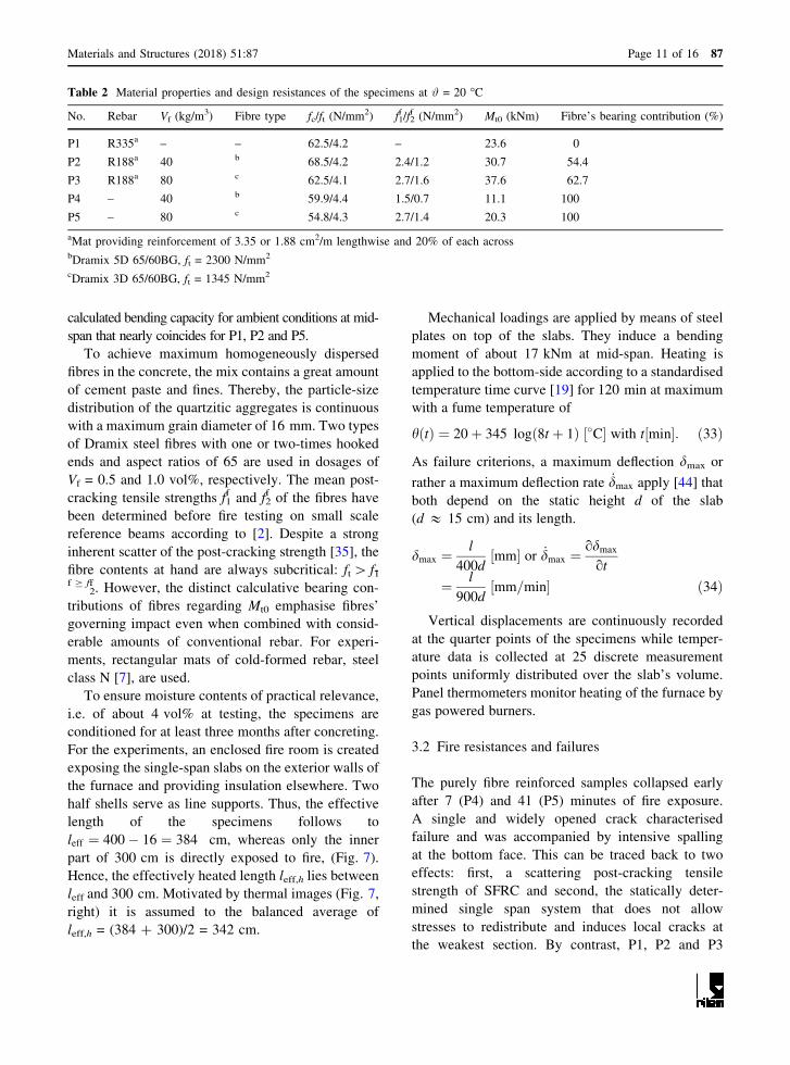
calculated bending capacity for ambient conditions at mid-
span that nearly coincides for P1, P2 and P5.
To achieve maximum homogeneously dispersed
fibres in the concrete, the mix contains a great amount
of cement paste and fines. Thereby, the particle-size
distribution of the quartzitic aggregates is continuous
with a maximum grain diameter of 16 mm. Two types
of Dramix steel fibres with one or two-times hooked
ends and aspect ratios of 65 are used in dosages of
Vf = 0.5 and 1.0 vol%, respectively. The mean post-
cracking tensile strengths f1f and f2
f of the fibres have
been determined before fire testing on small scale
reference beams according to [2]. Despite a strong
inherent scatter of the post-cracking strength [35], the
fibre contents at hand are always subcritical: ft[ f1-f C f
2f . However, the distinct calculative bearing con-
tributions of fibres regarding Mt0 emphasise fibres’
governing impact even when combined with consid-
erable amounts of conventional rebar. For experi-
ments, rectangular mats of cold-formed rebar, steel
class N [7], are used.
To ensure moisture contents of practical relevance,
i.e. of about 4 vol% at testing, the specimens are
conditioned for at least three months after concreting.
For the experiments, an enclosed fire room is created
exposing the single-span slabs on the exterior walls of
the furnace and providing insulation elsewhere. Two
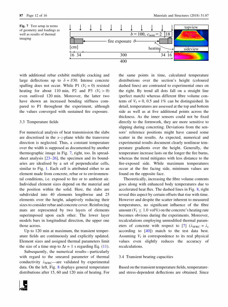
half shells serve as line supports. Thus, the effective
length of the specimens follows to
leff ¼ 400� 16 ¼ 384 cm, whereas only the inner
part of 300 cm is directly exposed to fire, (Fig. 7).
Hence, the effectively heated length leff,h lies between
leff and 300 cm. Motivated by thermal images (Fig. 7,
right) it is assumed to the balanced average of
leff,h = (384 ? 300)/2 = 342 cm.
Mechanical loadings are applied by means of steel
plates on top of the slabs. They induce a bending
moment of about 17 kNm at mid-span. Heating is
applied to the bottom-side according to a standardised
temperature time curve [19] for 120 min at maximum
with a fume temperature of
hðtÞ ¼ 20þ 345 logð8t þ 1Þ �C½ � with t min½ �: ð33Þ
As failure criterions, a maximum deflection dmax or
rather a maximum deflection rate _dmax apply [44] that
both depend on the static height d of the slab
(d & 15 cm) and its length.
dmax ¼l
400dmm½ � or _dmax ¼
odmax
ot
¼ l
900dmm=min½ � ð34Þ
Vertical displacements are continuously recorded
at the quarter points of the specimens while temper-
ature data is collected at 25 discrete measurement
points uniformly distributed over the slab’s volume.
Panel thermometers monitor heating of the furnace by
gas powered burners.
3.2 Fire resistances and failures
The purely fibre reinforced samples collapsed early
after 7 (P4) and 41 (P5) minutes of fire exposure.
A single and widely opened crack characterised
failure and was accompanied by intensive spalling
at the bottom face. This can be traced back to two
effects: first, a scattering post-cracking tensile
strength of SFRC and second, the statically deter-
mined single span system that does not allow
stresses to redistribute and induces local cracks at
the weakest section. By contrast, P1, P2 and P3
Table 2 Material properties and design resistances of the specimens at # = 20 �C
No. Rebar Vf (kg/m3) Fibre type fc/ft (N/mm2) f1
f /f2f (N/mm2) Mt0 (kNm) Fibre’s bearing contribution (%)
P1 R335a – – 62.5/4.2 – 23.6 0
P2 R188a 40 b 68.5/4.2 2.4/1.2 30.7 54.4
P3 R188a 80 c 62.5/4.1 2.7/1.6 37.6 62.7
P4 – 40 b 59.9/4.4 1.5/0.7 11.1 100
P5 – 80 c 54.8/4.3 2.7/1.4 20.3 100
aMat providing reinforcement of 3.35 or 1.88 cm2/m lengthwise and 20% of each acrossbDramix 5D 65/60BG, ft = 2300 N/mm2
cDramix 3D 65/60BG, ft = 1345 N/mm2
Materials and Structures (2018) 51:87 Page 11 of 16 87
with additional rebar exhibit multiple cracking and
large deflections up to d = l/30. Intense concrete
spalling does not occur. While P1 (Vf = 0) resisted
heating for about 110 min, P2 and P3 (Vf[ 0)
even outlived 120 min. Moreover, the latter two
have shown an increased bending stiffness com-
pared to P1 throughout the experiment, although
the values converged with sustained fire exposure.
3.3 Temperature fields
For numerical analysis of heat transmission the slabs
are discretised in the x–z-plane while the transverse
direction is neglected. Thus, a constant temperature
over the width is supposed as documented by another
thermographic image in Fig. 7, right, too. In spread-
sheet analysis [23–26], the specimen and its bound-
aries are idealised by a set of perpendicular cells,
similar to Fig. 1. Each cell is attributed either to an
element made from concrete, rebar or to environmen-
tal conditions, i.e. exposed to fire or to ambient air.
Individual element sizes depend on the material and
the position within the solid. Here, the slabs are
subdivided into 40 elements lengthwise and 25
elements over the height, adaptively reducing their
sizes to consider rebar and concrete cover. Reinforcing
mats are represented by two layers of elements
superimposed upon each other. The lower layer
models bars in longitudinal direction, the upper one
those across.
Up to 120 min at maximum, the transient temper-
ature fields are continuously and explicitly updated.
Element sizes and assigned thermal parameters limit
the size of a time step to Dt = 1 s regarding Eq. (11).
Subsequently, the numerical results—particularly
with regard to the smeared parameter of thermal
conductivity kSFRC—are validated by experimental
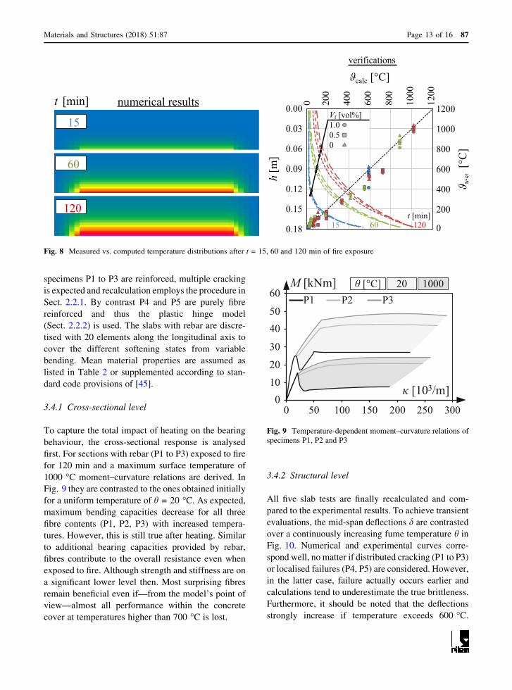
data. On the left, Fig. 8 displays general temperature
distributions after 15, 60 and 120 min of heating. For
the same points in time, calculated temperature
distributions over the section’s height (coloured
dashed lines) are contrasted to experimental ones on
the right. By trend all dots fall on a straight line
(perfect match) whereas different fibre volume con-
tents of Vf = 0, 0.5 and 1% can be distinguished. In
detail, temperatures are assessed at the top and bottom
side as well as at five additional points across the
thickness. As the inner sensors could not be fixed
directly to the formwork, they are more sensitive to
slipping during concreting. Deviations from the sen-
sors’ reference positions might have caused some
scatter in the results. As expected, numerical and
experimental results document clearly nonlinear tem-
perature gradients over the height. Generally, the
temperature increase lasts on the longer the fire burns,
whereas the trend mitigates with less distance to the
fire-exposed side. While maximum temperatures
occur at the fire facing side, minimum values are
found on the opposite face.
Theoretically, increasing the fibre volume contents
goes along with enhanced body temperatures due to
accelerated heat flux. The dashed lines in Fig. 8, right
reveal this aspect by certain offsets that rise with time.
However and despite the scatter inherent to measured
temperatures, no significant influence of the fibre
amount (Vf B 1.0 vol%) on the concrete’s heating rate
becomes obvious during the experiments. Moreover,
recalculations employing unmodified thermal param-
eters of concrete with respect to [7] (kSFRC = kcaccording to [40]) match to the test data best.
Assuming Vf in correspondence to its real physical
values even slightly reduces the accuracy of
recalculations.
3.4 Transient bearing capacities
Based on the transient temperature fields, temperature-
and stress-dependent deflections are obtained. Since
16343416
18
300
[cm] fire exposure
400
b = 100, cnom = 2
heating
topview
sideview
Fig. 7 Test setup in terms
of geometry and loadings as
well as results of thermal
imaging
87 Page 12 of 16 Materials and Structures (2018) 51:87
specimens P1 to P3 are reinforced, multiple cracking
is expected and recalculation employs the procedure in
Sect. 2.2.1. By contrast P4 and P5 are purely fibre
reinforced and thus the plastic hinge model
(Sect. 2.2.2) is used. The slabs with rebar are discre-
tised with 20 elements along the longitudinal axis to
cover the different softening states from variable
bending. Mean material properties are assumed as
listed in Table 2 or supplemented according to stan-
dard code provisions of [45].
3.4.1 Cross-sectional level
To capture the total impact of heating on the bearing
behaviour, the cross-sectional response is analysed
first. For sections with rebar (P1 to P3) exposed to fire
for 120 min and a maximum surface temperature of
1000 �C moment–curvature relations are derived. In
Fig. 9 they are contrasted to the ones obtained initially
for a uniform temperature of h = 20 �C. As expected,maximum bending capacities decrease for all three
fibre contents (P1, P2, P3) with increased tempera-
tures. However, this is still true after heating. Similar
to additional bearing capacities provided by rebar,
fibres contribute to the overall resistance even when
exposed to fire. Although strength and stiffness are on
a significant lower level then. Most surprising fibres
remain beneficial even if—from the model’s point of
view—almost all performance within the concrete
cover at temperatures higher than 700 �C is lost.
3.4.2 Structural level
All five slab tests are finally recalculated and com-
pared to the experimental results. To achieve transient
evaluations, the mid-span deflections d are contrasted
over a continuously increasing fume temperature h in
Fig. 10. Numerical and experimental curves corre-
spond well, no matter if distributed cracking (P1 to P3)
or localised failures (P4, P5) are considered. However,
in the latter case, failure actually occurs earlier and
calculations tend to underestimate the true brittleness.
Furthermore, it should be noted that the deflections
strongly increase if temperature exceeds 600 �C.
t [min]
15
60
120
numerical results
calc [°C]
test
[°C
]
h[m
]
0
200
400
600
800
1000
12000.00
0.03
0.06
0.09
0.12
0.15
0.18
0 200
400
600
800
1000
1200
verifications
Vf [vol%]1.00.50
t [min]6015 120
Fig. 8 Measured vs. computed temperature distributions after t = 15, 60 and 120 min of fire exposure
M [kNm]
[103/m]0
10
20
30
4050
60
0 50 100 150 200 250 300
1000 [°C] 20P1 P2 P3
Fig. 9 Temperature-dependent moment–curvature relations of
specimens P1, P2 and P3
Materials and Structures (2018) 51:87 Page 13 of 16 87

While temperature effects dominate at that point,
stress induced portions become important.
4 Conclusions
Within this contribution, a thermo-mechanical model
is proposed to investigate transient bearing capacities
of SFRC slabs with and without additional rebar
exposed to elevated temperatures. The temperature-
dependent tensile strength of the SFRC is derived
based on test results from the literature. The accuracy
of the coupled model is validated using results
obtained from large-scale fire tests performed on
reinforced concrete slabs. Both tests and numerical
data are, on average, in good agreement. Based on the
presented research, the following conclusions can be
drawn:
• Concrete’s heating rate is not significantly
enhanced by steel fibres in dosages up to about
1.0% in volume. The thermal parameters describ-
ing heat capacity, density and conductivity as well
as the thermal expansion coefficient of PC can be
adopted for SFRC as a first order estimate.
• The temperature-dependent but strain-independent
softening of fibre’s post-cracking tensile strength
can be reliably predicted by means of a bilinear
function, as originally proposed in [40]. This
function assumes undisturbed conditions until the
solid temperature reaches 150 �C and assumes a
full loss of bearing capacity at 700 �C.• SFRC without rebar might extensively spall when
subjected to fire. Brittle failure was observed in the
single-span systems very early after fire exposure,
i.e. after 7 and 41 min, due to single cracking. In
both cases, the radiation temperature of the fumes
did not exceed approximately 600 �C.• SFRC containing additional rebar exhibits multi-
ple cracking, pronounced deflections and reduced
spalling. The ratio of specimen’s length to its
maximum vertical deflection reaches about d = l/
30. Thus, a ductile material behaviour prevails up
to about 1000 �C of outer exposure.
• The combination of mechanically anchored steel
fibres and rebar results in enhanced fire resistance
durations and higher bending stiffness compared to
reinforced concrete. However, the necessary resid-
ual strength values corresponding to fire resistance
durations of 90 min (R90) could be met in both
cases.
Acknowledgements The financial support provided by NV
Bekaert SA for the presented experiments is gratefully
acknowledged. Additionally, the authors would like to thank
Prof. Catherina Thiele as well as Daniele Casucci, M.Sc. from
TU Kaiserslautern, Germany for careful execution of all tests.
The authors very much appreciate the support of Dr. M. A.
Ahrens in elaborating the paper.
[°C]
[mm]
0
40
80
120
160 P1: R335testcalc.
[°C]
[mm]
0
40
80
120
160 P2: R188+40kg/m³testcalc.
[°C]
[mm]
0 400 800 1200 0 400 800 1200 0 400 800 12000
40
80
120
160 P3: R188+80kg/m³testcalc.
[°C]
[mm]
0
20
40
60
100P4: 40 kg/m³testcalc.
80
[°C]
[mm]
0 200 600 1000 0 200 600 10000
20
40
60
100P5: 80 kg/m³testcalc.
80
Fig. 10 Measured versus
calculated temperature-
dependent deflections at
mid-span
87 Page 14 of 16 Materials and Structures (2018) 51:87

Compliance with ethical standards
Conflict of interest The authors declare that they have no
conflict of interest.
References
1. RILEM TC 162-TDF (2003) Test and design methods for
steel fibre reinforced concrete—background and experi-
ences. In: Schnutgen B, Vandevalle L (eds) Proceedings of
31 RILEM TC-162-TDF workshop, Bochum, Germany
2. DAfStb (German Committee for Structural Concrete)
(2015) DAfStb H614-2015 commentary on the DAfStb
guideline ‘‘steel fibre reinforced concrete’’, Berlin
3. Model Code 2010 (2013) fib model code 2010. Federation
Internationale du Beton
4. Godde L, Strack M, Mark P (2010) Bauteile aus
Stahlfaserbeton und stahlfaserverstarktem Stahlbeton—
Hilfsmittel fur Bemessung und Verformungsabschatzung
nach DAfStb-Richtlinie Stahlfaserbeton. Beton- und
Stahlbetonbau 105(2):78–91
5. Heek P, Mark P (2016) Load-bearing capacities of SFRC
elements accounting for tension stiffening with modified
moment–curvature relations. In: ACI-SP 310 ? fib bulletin
no. 79: fibre reinforced concrete—from design to structural
applications, pp 301–310
6. Dehn F, Herrmann A (2014) Steel fibre-reinforced concrete
(SFRC) in fire—normative and pre-normative requirements
and code-type regulations. In: Proceedings of 1st joint ACI-
fib international work. Fibre reinforced concrete—from
design to structural applications, Canada, pp 2–8
7. DIN EN 1992-1-2 (2010) Design of concrete structures—
part 1–2: general rules—structural fire design, Berlin
8. Khaliq W, Kodur V (2011) Thermal and mechanical prop-
erties of fibre reinforced high performance self-consolidat-
ing concrete at elevated temperatures. Cem Concr Res
41:1112–1122
9. Aslani F, Samali B (2014) Constitutive relationship for steel
fibre reinforced concrete at elevated temperatures. Fire
Technol 50:1249–1268
10. Chen GM, He YH, Yang H, Chen JF, Guo YC (2014)
Compressive behaviour of steel fibre reinforced recycled
aggregate concrete after exposure to elevated temperatures.
Constr Build Mater 71:1–15
11. Chen B, Liu J (2004) Residual strength of hybrid-fibre-re-
inforced high-strength concrete after exposure to high
temperatures. Cem Concr Res 34(6):1065–1069
12. Colombo M, di Prisco M, Felicetti R (2010) Mechanical
properties of steel fibre reinforced concrete exposed at high
temperatures. Mater Struct 43:475–491
13. Faiyadh FI, Al-Ausi MA (1989) Effect of elevated tem-
perature in splitting tensile strength of fibre concrete. Int J
Cem Compos Lightweight Concr 11(3):175–178
14. Kim J, Lee G-P, Moon DY (2015) Evaluation of mechanical
properties of steel-fibre-reinforced concrete exposed to high
temperatures by double-punch test. Constr Build Mater
79:182–191
15. Peng GF, Yang WW, Zhao J, Liu YF, Bian SH, Zhao LH
(2006) Explosive spalling and residual mechanicalproperties of fibre-toughened high-performance concrete
subjected to high temperatures. Cem Concr Res 36:723–727
16. Suhaendi SL, Horiguchi T (2006) Effect of short fibres on
residual permeability and mechanical properties of hybrid
fibre reinforced high strength concrete after heat exposure.
Cem Concr Res 36:1672–1678
17. Diederichs U (1999) Hochtemperatur- und Brandverhalten
von hochfestem Stahlfaserbeton. In: Teutsch M (ed)
Betonbau – Forschung, Entwicklung und Anwendung, vol
142. Schriftenreihe des Instituts fur Baustoffe, Massivbau
und Brandschutz, Braunschweig, pp 67–76
18. Hertel C, Orgass M, Dehn F (2002) Brandverhalten von
faserfreiem und faserverstarktem Beton. In: Konig G, Hol-
schemacher K, Dehn F (eds) Faserbeton – Innovationen im
Bauwesen. Bauwerk Verlag, pp 63–76
19. DIN EN 1991-1-2 (2010) Actions on structures—part 1–2:
general actions—actions in structures exposed to fire, Berlin
20. Carslaw HS, Jaeger JC (1959) Conduction of heat in solids,
2nd edn. Oxford University Press, Oxford
21. Mannsfeld T (2011) Tragverhalten von Stahlbetonflachen-
tragwerken unter Berucksichtigung der temperaturbed-
ingten Nichtlinearitaten im Brandfall. Dissertation, TU
Wuppertal
22. Lichte U (2004) Klimatische Temperatureinwirkungen und
Kombinationsregeln bei Bruckenbauwerken. Ph.D. thesis,
Munchen, Germany
23. Sanio D, Mark P, Ahrens MA (2017) Temperaturfeld-
berechnung fur Brucken: Umsetzung mit Tabellenkalkula-
tionen. Beton- und Stahlbetonbau 112(2):85–95
24. Mark P (2003) Optimierungsmethoden zur Biegebemes-
sung von Stahlbetonquerschnitten. Beton- und Stahlbeton-
bau 98(9):511–519
25. Mark P, Strack M (2004) Bending design of arbitrarily
shaped steel fibre reinforced concrete sections using opti-
mization methods. In: di Prisco M et al. (eds) 6th RILEM
symposium fibre reinforced concrete (BEFIB 2004), Italy,
pp 965–974
26. Mark P (2004) Fundamentgestaltung und Sohlspannungs-
berechnung mit Optimierungsmethoden und Tabel-
lenkalkulation. Bautechnik 81(1):38–43
27. Tkocz J, Heek P, Mark P (2015) SFRC slabs exposed to
fire—experiments, temperature flow and design. ALITin-
form 6(41):36–53
28. Hosser D (2013) Leitfaden Ingenieurmethoden des
Brandschutzes. vfdb TB 04-01/3
29. Fouad N (1998) Numerical simulation of the environmental
thermal loading of structures. Fraunhofer-IRB, Munich
30. Bhatti A (2002) Practical optimization methods. Springer,
New York
Materials and Structures (2018) 51:87 Page 15 of 16 87
Open Access This article is distributed under the terms of the
Creative Commons Attribution 4.0 International License (http://
creativecommons.org/licenses/by/4.0/), which permits use,
duplication, adaptation, distribution and reproduction in any
medium or format, as long as you give appropriate credit to the
original author(s) and the source, provide a link to the Creative
Commons license and indicate if changes were made.

34. Bazant ZP, Oh BH (1983) Crack band theory for fracture of
concrete. Mater Struct 16(93):155–197
35. Heek P, Ahrens MA, Mark P (2017) Incremental-iterative
model for time-variant analysis of SFRC subjected to flex-
ural fatigue. Mater Struct 50(1):62. https://doi.org/10.1617/
s11527-016-0928-z
36. Heek P, Tkocz J, Thiele C, Vitt G, Mark P (2015) Fasern
unter Feuer - Bemessungshilfen fur stahlfaserverstarkte
Stahlbetondeckenplatten im Brandfall. Beton- und
Stahlbetonbau 110(10):656–671
37. DIN EN 1993-1-2 (2010) Design of steel structures—part
1–2: general rules—structural fire design, Berlin
38. Cook DJ, Uher C (1974) The thermal conductivity of fibre-
reinforced concrete. Cem Concr Res 4:497–509
39. Nagy B, Nehme SG, Szagri D (2015) Thermal properties
andmodeling of fiber reinforced concretes. Energy Procedia
78:2742–274740. DBV (Deutscher Beton- und Bautechnik Verein e.V.)
(2001) DBV-2001: Merkblatt Stahlfaserbeton
41. Balazs G, Lubloy E (2012) Reinforced concrete structures
in and after fire. Concr Struct 13:72–80
42. Holschemacher K, Weiße D (2004) Bond of reinforcement
in fibre reinforced concrete. In: Proceedings of 6th RILEM
symposium on fibre reinforced concrete, BEFIB, Italy,
pp 349–358
43. Godde L, Mark P (2015) Numerical simulation of the
structural behaviour of SFRC slabs with or without rebar
and prestressing. Mater Struct 48(6):1689–1701
44. DIN EN 1365-2 (2012) Fire resistance tests for loadbearing
elements—part 2: floors and roofs, Berlin
45. DIN EN 1992-1-1 (2011) Design of concrete structures—
part 1-1: general rules and rules for buildings, Berlin
87 Page 16 of 16 Materials and Structures (2018) 51:87
fictitious crack model, particularly for fibre reinforced
concrete. Int J Cem Compos 2(4):177–184
33. Strack M (2008) Modelling of the crack opening controlled
load bearing behaviour of steel fibre reinforced concrete
under tension and bending. In: Gettu R (eds) Proceedings of
7th RILEM international symposium fibre reinforced con-
crete—design and applications, BEFIB, India, pp 323–332
31. Konig G, Tue NV (2003) Grundlagen des Stahlbetonbaus –
Einfuhrung in die Bemessung nach DIN 1045-1. Teubner-
Verlag, Leipzig
32. Hillerborg A (1980) Analysis of fracture by means of the