scanfibre - products for engineered concrete · scanfibre steel fibre reinforced concrete (sfrc) is...
TRANSCRIPT
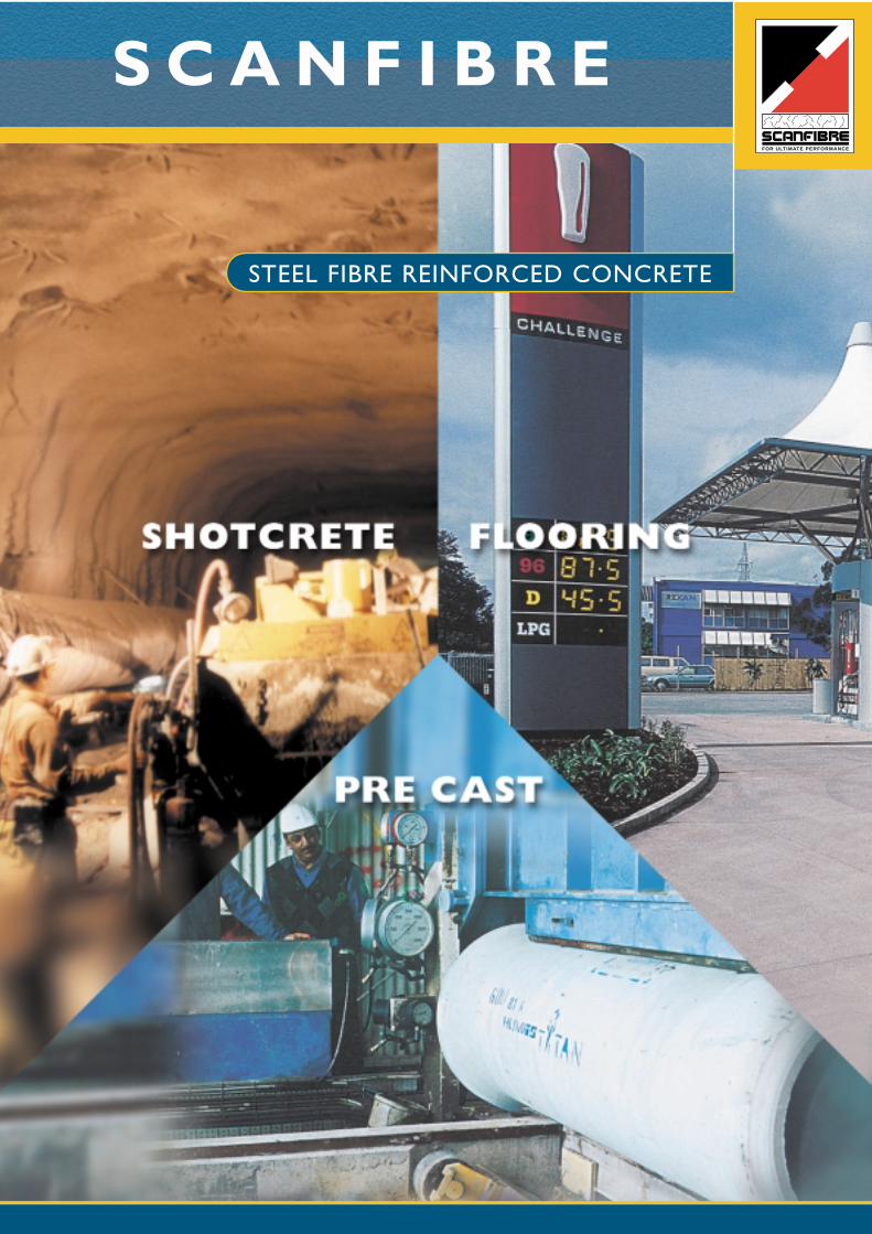
FOR ULTIMATE PERFORMANCE
STEEL FIBRE REINFORCED CONCRETE
S C A N F I B R E
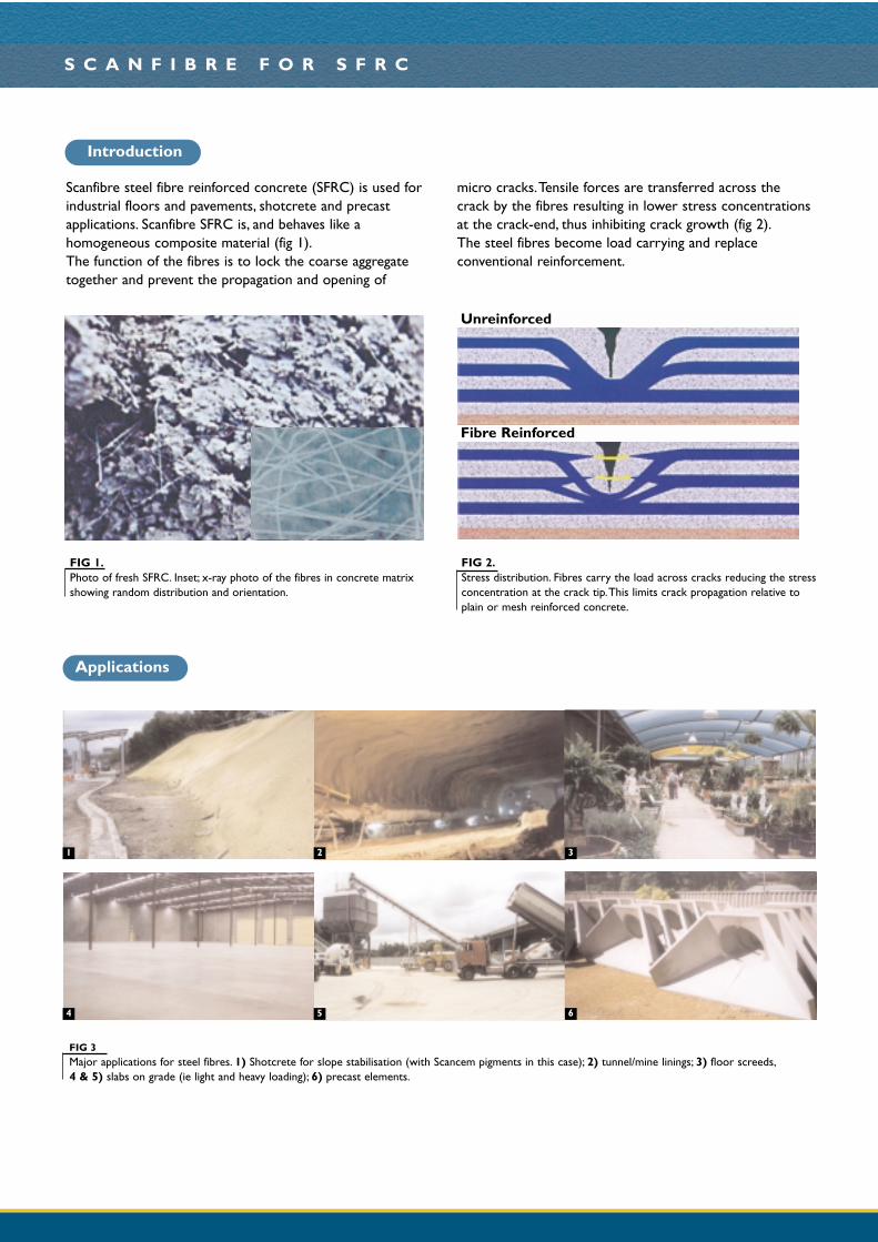
Scanfibre steel fibre reinforced concrete (SFRC) is used forindustrial floors and pavements, shotcrete and precastapplications. Scanfibre SFRC is, and behaves like ahomogeneous composite material (fig 1).The function of the fibres is to lock the coarse aggregatetogether and prevent the propagation and opening of
micro cracks.Tensile forces are transferred across thecrack by the fibres resulting in lower stress concentrationsat the crack-end, thus inhibiting crack growth (fig 2).The steel fibres become load carrying and replaceconventional reinforcement.
S C A N F I B R E F O R S F R C
FIG 3Major applications for steel fibres. 1) Shotcrete for slope stabilisation (with Scancem pigments in this case); 2) tunnel/mine linings; 3) floor screeds,4 & 5) slabs on grade (ie light and heavy loading); 6) precast elements.
FIG 1.Photo of fresh SFRC. Inset; x-ray photo of the fibres in concrete matrixshowing random distribution and orientation.
FIG 2.Stress distribution. Fibres carry the load across cracks reducing the stressconcentration at the crack tip.This limits crack propagation relative toplain or mesh reinforced concrete.
Unreinforced
Fibre Reinforced
Applications
Introduction
1 2
4 5
3
6
S C A N F I B R E F O R S F R C
Compared to MeshEliminates spalling of concrete due to steel corrosion.Fibre reinforcement is supplied by quality assuredpremixed concrete plants.Eliminates concern than mesh may not be placed at theright location.Saves the cost of placing mesh.Increases construction speed.
Reduces edge and joint damage.
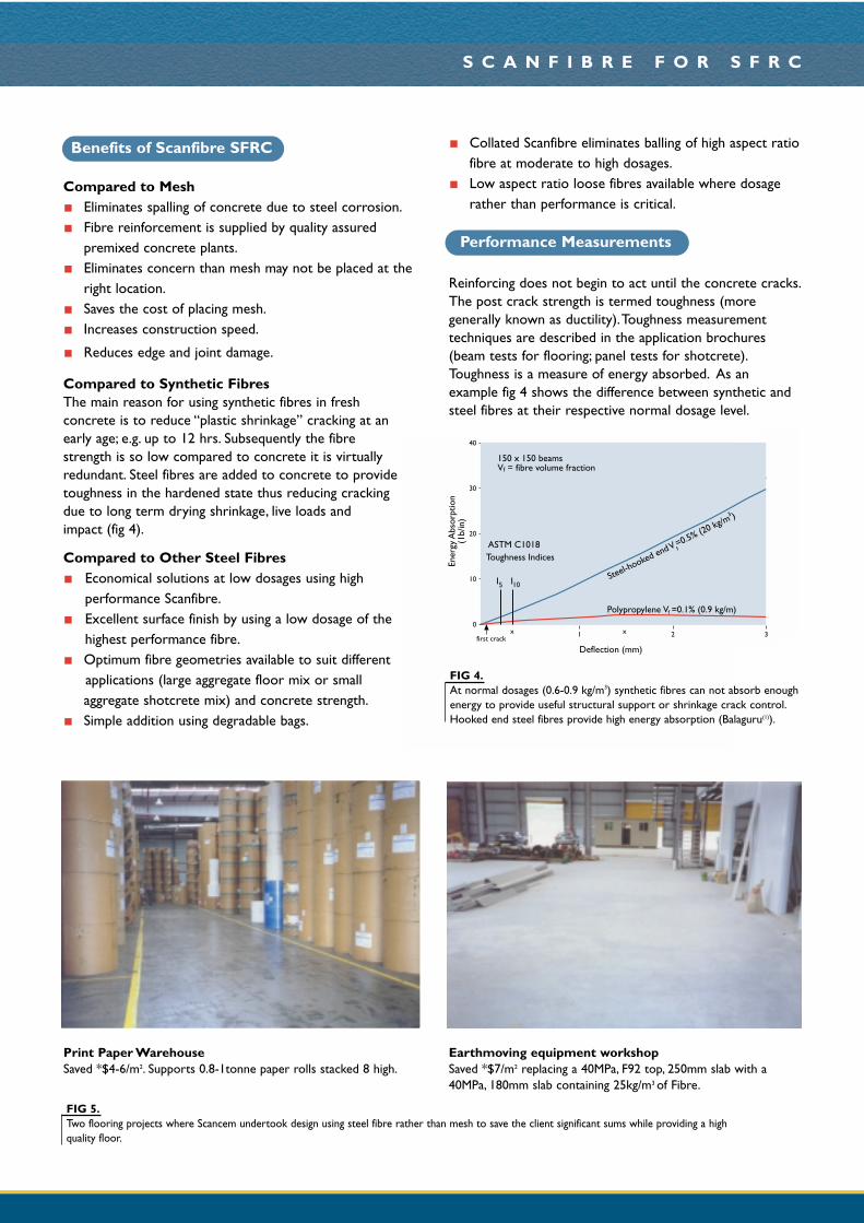
Compared to Synthetic FibresThe main reason for using synthetic fibres in freshconcrete is to reduce “plastic shrinkage” cracking at anearly age; e.g. up to 12 hrs. Subsequently the fibrestrength is so low compared to concrete it is virtuallyredundant. Steel fibres are added to concrete to providetoughness in the hardened state thus reducing crackingdue to long term drying shrinkage, live loads and impact (fig 4).
Compared to Other Steel FibresEconomical solutions at low dosages using highperformance Scanfibre.Excellent surface finish by using a low dosage of thehighest performance fibre.Optimum fibre geometries available to suit different applications (large aggregate floor mix or smallaggregate shotcrete mix) and concrete strength.Simple addition using degradable bags.
Collated Scanfibre eliminates balling of high aspect ratiofibre at moderate to high dosages.Low aspect ratio loose fibres available where dosagerather than performance is critical.
Reinforcing does not begin to act until the concrete cracks.The post crack strength is termed toughness (moregenerally known as ductility).Toughness measurementtechniques are described in the application brochures(beam tests for flooring; panel tests for shotcrete).Toughness is a measure of energy absorbed. As anexample fig 4 shows the difference between synthetic andsteel fibres at their respective normal dosage level.
FIG 5.Two flooring projects where Scancem undertook design using steel fibre rather than mesh to save the client significant sums while providing a highquality floor.
Ener
gy A
bsor
ptio
n(1
b/in
)
Balagura & Shah
Polypropylene
Vf=0.5%
3 )
Steel-hooked end
Steel-hooked end150 x 150 beamsVf = fibre volume fraction
ASTM C1018Toughness Indices
I5 I10
Polypropylene Vf =0.1% (0.9 kg/m)
Steel-hooked end V f=0.5% (20 kg/m
3 )
Deflection (mm)first crack
40
30
20
10
01 2 3x x
FIG 4.At normal dosages (0.6-0.9 kg/m3) synthetic fibres can not absorb enoughenergy to provide useful structural support or shrinkage crack control.Hooked end steel fibres provide high energy absorption (Balaguru(1)).
Print Paper WarehouseSaved *$4-6/m2. Supports 0.8-1tonne paper rolls stacked 8 high.
Earthmoving equipment workshopSaved *$7/m2 replacing a 40MPa, F92 top, 250mm slab with a40MPa, 180mm slab containing 25kg/m3 of Fibre.
Benefits of Scanfibre SFRC
Performance Measurements
S C A N F I B R E F O R S F R C
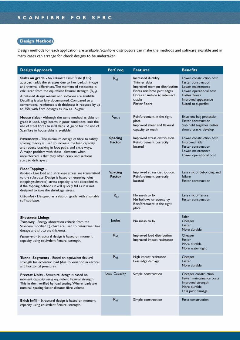
Design Methods
Design methods for each application are available. Scanfibre distributors can make the methods and software available and inmany cases can arrange for check designs to be undertaken.
Design Approach
Slabs on grade - An Ultimate Limit State (ULS)approach adds the stresses due to live load, shrinkageand thermal differences.The moment of resistance iscalculated from the equivalent flexural strength (Re3).
A detailed design manual and software are available.Detailing is also fully documented. Compared to aconventional reinforced slab thickness is reduced by upto 25% with fibre dosages as low as 15kg/m3.
House slabs - Although the same method as slabs ongrade is used, edge beams in poor conditions limit theuse of steel fibres to infill slabs. A guide for the use ofScanfibre in house slabs is available.
Pavements - The minimum dosage of fibre to satisfyspacing theory is used to increase the load capacityand reduce cracking in foot paths and cycle ways.A major problem with these elements whenunreinforced is that they often crack and sections start to drift apart.
Floor Toppings -Bonded - Live load and shrinkage stress are transmittedto the substrate. Design is based on ensuring joint(topping/substrate) stress capacity is not exceeded as if the topping debonds it will quickly fail as it is notdesigned to take the shrinkage stress.
Unbonded - Designed as a slab on grade with a suitablystiff sub-base.
Shotcrete Linings Temporary - Energy absorption criteria from theScancem modified Q chart are used to determine fibredosage and shotcrete thickness.
Permanent - Structural design is based on momentcapacity using equivalent flexural strength.
Tunnel Segments - Based on equivalent flexuralstrength for eccentric load (due to variation in verticaland horizontal pressure).
Precast Units - Structural design is based onmoment capacity using equivalent flexural strength.This in then verified by load testing.Where loads arenominal, spacing factor dictates fibre volume.
Brick Infill - Structural design is based on momentcapacity using equivalent flexural strength.
Perf. req
Re3
R10,30
Spacing Factor
Spacing Factor
Re3
Joules
Re3
Re3
Load Capacity
Re3
Features
Increased ductilityThinner slabs.Improved moment distributionFibres reinforce joint edgesFibres at surface to intersectcracksFlatter floors
Reinforcement in the rightplaceImproved shear and flexuralcapacity to mesh
Improved stress distribution.Reinforcement correctlylocated
Improved stress distribution.Reinforcement correctlylocated
No mesh to fixNo hollows or oversprayReinforcement in the rightplace
No mesh to fix
Improved load distributionImproved impact resistance
High impact resistanceLess edge damage
Simple construction
Simple construction
Benefits
Lower construction costFaster constructionLower maintenanceLower operational costFlatter floorsImproved appearanceSuited to superflat
Excellent bug protectionFaster constructionSlab held together bettershould cracks develop
Lower construction costImproved rideFaster constructionLower maintenanceLower operational cost
Less risk of debonding andfailureFaster construction
Less risk of failureFaster construction
SaferCheaperFasterMore durable
CheaperFasterMore durableMore water tight
CheaperFasterMore durable
Cheaper constructionFewer maintainance costsImproved strengthMore durableLess joint damage
Fasta construction
S C A N F I B R E F O R S F R C
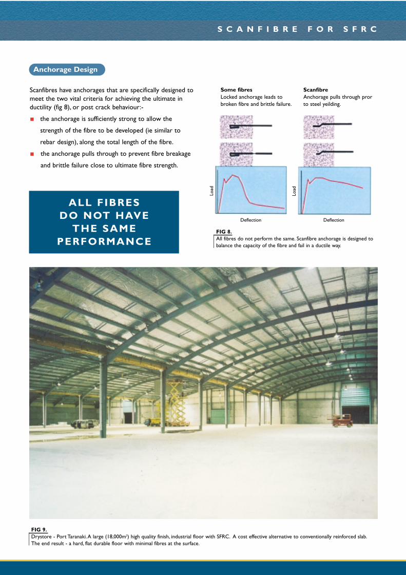
Scanfibres have anchorages that are specifically designed tomeet the two vital criteria for achieving the ultimate inductility (fig 8), or post crack behaviour:-
the anchorage is sufficiently strong to allow the
strength of the fibre to be developed (ie similar to
rebar design), along the total length of the fibre.
the anchorage pulls through to prevent fibre breakage
and brittle failure close to ultimate fibre strength.
FIG 9.Drystore - Port Taranaki.A large (18,000m2) high quality finish, industrial floor with SFRC. A cost effective alternative to conventionally reinforced slab.The end result - a hard, flat durable floor with minimal fibres at the surface.
FIG 8.All fibres do not perform the same. Scanfibre anchorage is designed tobalance the capacity of the fibre and fail in a ductile way.
Deflection Deflection
ALL FIBRES DO NOT HAVE
THE SAMEPERFORMANCE
Anchorage Design
Load
Load
Some fibres Locked anchorage leads tobroken fibre and brittle failure.
ScanfibreAnchorage pulls through prorto steel yeilding.
1.1
1.0
0.9
0.8
0.7
0.6
0.5
0.4
0.3
0.2
0.1
00 0.5 1.0 1.5 2.0
Steel fibreExperimental resultsResults from thetheoretical analysis
Ave
rage
cra
ck w
idth
(m
m)
(0.044 in.)
Fiber volume (%)Average crack width versus fiber volume: steel fibers
0
200
400
600
800
1000
1200
1400
1600
1800
Joule
s
Based on Scancem results
Har
ex
EE18
EE25
EE25
HT
Xor
ex
Dra
mix
Scan
fibre
8mm
bar
at
200m
m c
/cs
4mm
bar
at
150m
m c
/cs
Plai
n
Fibres
Testing at UniversityOf Western Sydney
all at 50kg/m3
ACI committee 544"Measurement Of Properties Of Fibre Reinforced Concrete"
0
10
20
30
40
50
60
70
PlainConcrete
84kg/m3
Straight
48kg/m3 Hooked End
No
of B
low
s
100
95
95
95
95
95100 1000 10,000 100,000
Number of Load Cycles N
0%
0.5% straight
1.0% straight
0.6% hooked end
fibre % by volume
% o
f fle
xura
l str
engt
h
first crack
failure
High Ductility
Ductility is a measure of the post crack strength.These
results for 50kg/m3 show performance of one high
performance Scanfibre is comparable to heavy mesh and
outperforms some fibres by 3x (ref Clements (1994))
Exceptional Impact ResistanceSteel fibres provide high impact resistance as the concretecontinues to carry load after cracking. (ref Balaguru 1992)
Excellent Crack Distribution
Scanfibre carries the load across cracks leading to excellent
crack distribution and minimal crack width at low dosage of
fibres.
High Fatigue ResistanceBy preventing crack propagation Scanfibres give high fatigueperformance.
S C A N F I B R E F O R S F R C
FIG 9.Shotcrete panels tested according to EFNARC standards comparingvarious steel fibres types and mesh (ref Clements (1994)). Hooked endfibres tend to give higher load capacity at lower deflections than meshand far better performance than other types of fibre.
FIG 10.Balaguru (1992) showed that the crack distribution effect of fibres inpractice matched predicted performance.
FIG 11.Impact test involves supporting a slab on its perimeter rim andrepetitively dropping a ball on it from a standard height (Balaguru(1)).
FIG 12.The performance of the fibre reinforcement determines the percentage ofthe flexural strength at any number of cycles.
Impact Test Results Fatigue of Concrete & SFRC
Scanfibre SFRC Performance
S C A N F I B R E F O R S F R C
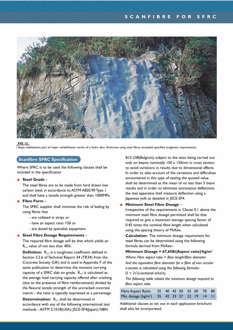
FIG 13.Slope stabilisation; part of major rehabilitation works of a hydro dam. Shotcrete using steel fibres exceeded specified toughness requirements.
Where SFRC is to be used the following clauses shall beincluded in the specification
Steel Grade -The steel fibres are to be made from hard drawn lowcarbon steel, in accordance to ASTM A820.90 Type 1and shall have a tensile strength greater than 1000MPa.Fibre Form -The SFRC supplier shall minimise the risk of balling byusing fibres that
- are collated in strips or- have an aspect ratio <50 or- are dosed by specialist equipment
Steel Fibre Dosage Requirements -The required fibre dosage will be that which yields anRe,3 value of not less than 40%.
Definition: Re,3 is a toughness coefficient defined inSection 3.2.6 of Technical Report 34 (TR34) from theConcrete Society (UK) and is used in Appendix F of thesame publication to determine the moment carryingcapacity of a SFRC slab on grade. Re,3 is calculated asthe average load carrying capacity offered after cracking(due to the presence of fibre reinforcement) divided bythe flexural tensile strength of the uncracked concretematrix - the ratio is typically expressed as a percentage.
Determination: Re,3 shall be determined inaccordance with any of the following international testmethods - ASTM C1018(USA); JSCE-SF4(Japan); NBN
B15-238(Belgium); subject to the tests being carried outonly on beams nominally 150 x 150mm in cross sectionto avoid variations in results due to dimensional effects.In order to take account of the variations and difficultiesencountered in this type of testing the quoted valueshall be determined as the mean of no less than 5 beamresults and in order to eliminate extraneous deflectionsthe test apparatus shall measure deflection using aJapanese yolk as detailed in JSCE-SF4.
Minimum Steel Fibre Dosage -Irrespective of the requirements in Clause 0.1 above theminimum steel fibre dosage permitted shall be thatrequired to give a maximum average spacing factor of0.45 times the nominal fibre length when calculatedusing the spacing theory of McKee.Calculation: The minimum dosage requirement forsteel fibres can be determined using the followingformula derived from McKee:-Minimum Dosage = 67,658/(Aspect ratio)2kg/m3
Where: Fibre aspect ratio = fibre length/fibre diameterAnd the equivalent fibre diameter for a fibre of non circularx-section is calculated using the following formula:- D = 2√(x-sectional area/π).The following table relates the minimum dosage required tofibre aspect ratio
Fibre Aspect Ratio 35 40 45 50 55 60 70 80Min. dosage (kg/m3) 55 42 33 27 22 19 14 11
Additional clauses as set out in each application brochureshall also be incorporated.
Scanfibre SFRC Specification

S C A N F I B R E F O R S F R C
Information in this brochure has been prepared by Scancem Materials. It cannot be reproduced or copied for any purpose without the written permission of Scancem Materials.While theinformation and / or specification contained herein is, to the best of our knowledge true and accurate, no warranty is given or implied in connection with any recommendation or suggestion,made by us or our representatives, agents or distributors as the conditions of use and any labour involved are beyond our control. Consult your nearest Scanfibre distributorsoffice for further information.
FOR ULTIMATE PERFORMANCE
Standard Scanfibre Nomenclature
C L
H N B6737DHookedEnd
DoubleAnchorage Aspect
RatioLength
NormalLowCarbon
BrightSteel
l/d
C
EX
AM
PLE
Collated
H
67
37
N
B G
O CD1. P.N. Balaguru, S.P. Shah “Fibre-Reinforced Cement
Composites” McGraw-Hill Inc. 1992 ISBN 0-07-056400-0
2. P.S. Mangat & K Gurasamy “Steel Fibre ReinforcedConcrete for Marine Applications” Proceedings of the 4thInternational Conference on the Behaviour of OffshoreStructures. Delft July 1985 pp 867-879
3 V.S. Gopalaratnam et al “Fracture Toughness of FibreReinforced Concrete” ACI Materials Journal Vol 84 No.4pp 339-354 1991
4 C.D. Johnston,A. Skarendahl “Comparative FlexuralPerformance Evaluation of Steel Fibre-Reinforced
Concretes According to ASTM C1018 show Importanceof Fibre Parimeters” Materials & Structures 1992.
5 L. Chen et al “ Comparative Toughness Testing of FibreReinforced Concrete”. ACI Salt Lake City Conference.
6 V. Ramakrishnan dal “Flexural Fatigue Strength, EnduranceLimit and Impact Strength of Fibre Reinforced Concrete”Transportation Research Record 1226. 1989.
7 C.H. Henager “The Use of Steel Fibre ReinforcedConcrete in Containment and Explosive ResistantStructures”. The Interaction in Non-nuclear Munitionswith Structures Part 1 1983.
Suggested Reading
The standard Scanfibre nomenclature is shown above. Each
item, as described below, indicates the range of fibres
Scancem can offer. Scancem will advise on the most
suitable fibre for each application.
Collated or LooseCollated Wire from forty spools is fed to a glue line
where a water dissolvable glue is applied.
Loose Loose fibres are more ecomonic but can only beused at low (<50) aspect ratios or with specialistautomated dosing equipment without balling.
Hooked EndAll Scanfibres have a hooked end.The hooked end is designedto provide anchorage in a non rigid way.The fibre crosssection remains unchanged so it can pull through theconcrete at high loads to prevent brittle failure due to fibrebreakage.This promotes high energy absorption.
Double or Zero or Continuous
For optimum performance fibre deformation has to increaseas concrete stength decreases to maintain balance betweenthe wire strength and its anchorage. Secondary anchorage, asdescribed here, achieve this.
Aspect ratio (ranges from 20-80)Aspect ratio (length/diameter) is a key characteristic indetermining performance. High aspect ratios lead to highperformance (toughness) but without collation fibres tend toball at aspect ratios over 50.
Length (range 18-60)Needs to be long enough to ensure aggregate overlap andshort enough not to block equipment.
NormalNormal low carbon steel is pulled through a series of dyes togive a wire strength in excess of 1000MPa
Bright GalvanisedBright steel is the norm for steel fibres in concrete.Corrosion is not generally an issue.The fibres are notinterconnected so there can be no corrosion current, hencegalvanising is not normally necessary.
Scanfibre distributors are able to provide technical supportrelated to design and construction of SFRC.This supports takes the form of:-
1 Liaison with the owner, architect, engineer and orcontractor to develop a cost effective and technicallyappropriate SFRC solution’s that invariably offersadvantages to all parties, ‘the win, win, win approach’
2 Formal training courses on the design of SFRC.
3 Structural design and detailing, full supported bywarranties.
4 Presentations at conferences.
5 Computer models are alson available to computingengineers.
6 Guidance on the placing of SFRC to achieve the
desired quality.
Technical Support