a u t i c s & aer journal of aeronautics & aerospace ... · wing were understood with help...
TRANSCRIPT

Volume 7 • Issue 1 • 1000207J Aeronaut Aerospace Eng, an open access journalISSN: 2168-9792
Open AccessResearch Article
Journal of Aeronautics & Aerospace EngineeringJo
urna
l of A
eron
autics & Aerospace Engineering
ISSN: 2168-9792
Khuntia and Ahuja, J Aeronaut Aerospace Eng 2018, 7:1DOI: 10.4172/2168-9792.1000207
Keywords: UAV wing; CATIA; CFD analysis; CFX; ANSYS; Contour of turbulence; Aspect ratio; Static pressure distribution; Flow analysis; Directional deformation
IntroductionUnmanned Aerial Vehicles (UAV) innovations started in the early
1900s which originally focused on providing practice targets for training military personnel. UAV development continued during World War I which led to the rise of early powered unmanned aerial combat vehicles (UCAV) in the year 1915 by Nikola Tesla. It was during World War II during which Nazi Germany used UAV for fly attack missions. Over last decade the impetuous on UAV or RPA (Remote Pilotless Aircraft) has increased manifold.
The age of the small UAV started in 1987, when Dr Paul MacCready's company AeroVironment developed the Pointer, the first hand-launched, backpack-carried UAV. Pointer combined the airframe technology of a high-performance model sailplane with an electric motor and propeller, a consumer video camera and a radio datalink. In 1999, the US Army bought four AeroVironment Pointer, small UAVs for testing in the service's "Military Operations in Urban Terrain" and was enthusiastic about the usefulness of the Pointer. In recent years small scale Drones have found their utility in a variety of important fields like Agriculture, e-Commerce, Logistics, urban warfare, Policing, Traffic management, climate monitoring, Land survey, Media coverage etc. The list is endless. Be it a large-scale aircraft or a small-scale UAV, the design process is iterative and follows a certain methodology. The process is iterative because the design parameters have to be evaluated over and over again so as to reach an optimal design. It is one of the most challenging fields in engineering and requires highly creative thinking. It requires a compromise between the various design parameters and eventually optimization [1-5].
Phases of aircraft design
The most important part of any aircraft design is the wing that provides lift to make it airborne. Hence Wing design has been analysed critically in this paper. However, this section gives a glimpse of complete design process. Aircraft design can be broken into three major phases namely Conceptual Design, Preliminary and Detailed design.
Conceptual design: This phase consists of selecting a basic design depending upon the requirements. It includes steps like initial requirements, approximate weight, draft design and the type of propulsion.
Preliminary design: This phase involves freezing of the configuration although it is open to minor revisions. Major components are designed in this stage followed by “lofting”. Lofting is modelling of outer skin of the aircraft with sufficient accuracy to ensure proper fit between different parts [6-8].
Detail design: This is the final phase in which the actual pieces to be built are designed which included detailed parts like individual ribs, spars etc. Another important part of detail design is called production design which determines how the airplane will be fabricated, starting with the smallest and simplest sub-assemblies and building up to the final assembly process.
The conceptual design process starts with the selection of suitable configuration, which determines the results of entire conceptual design process. Therefore, special care must be taken to choose a suitable but yet reasonable configuration in this stage. The entire conceptual design process is dependent on configuration. Hence, while choosing the configuration we must take into account the following subjects:
(a) Design requirements.
(b) Historical trends.
*Corresponding author: Khuntia SK, Head, Department of Aeronautics, Naval Institute of Aeronautical Technology Naval Base, Kochi-682004, India, Tel: +919969613377; E-mail: [email protected]
Received January 20, 2018; Accepted January 31, 2018; Published February 04, 2018
Citation: Khuntia SK, Ahuja AS (2018) Optimal Design and CFD Analysis of Wing of a Small-Scale UAV to Obtain Maximum Efficiency. J Aeronaut Aerospace Eng 7: 207. doi: 10.4172/2168-9792.1000207
Copyright: © 2018 Khuntia SK, et al. This is an open-access article distributed under the terms of the Creative Commons Attribution License, which permits unrestricted use, distribution, and reproduction in any medium, provided the original author and source are credited.
AbstractIn the recent past small-scale Unmanned Aerial Vehicles (or Unmanned Aerial System as it is called presently)
have evolved as an important tool in non-conventional fields like agriculture, e-Commerce, policing, medical logistics in addition to military applications. This paper presents the complete methodology (very limited article exists) applied to optimally design the wing of a small scale Unmanned Aerial Vehicle with help of widely used CFD software, ANSYS to maximize its efficiency. In this study, the application of computational methods in the iterative design process is successfully explored. The various design parameters and features of wing also have been explored with help of CFD analysis to derive the advantages. The strength and stiffness analysis of the UAV wing has also been carried out using ANSYS. The modelling of wing and associated parts were carried out on CATIA. The final design of the wing has two spars, 20 ribs a side with mid wing root strengthening, near elliptical planform and has an all composite structure. The wing is lighter in weight as compared to a similar wing made from Aluminum view weight optimization, and strong enough to meet all in-flight load conditions with safety margins. This paper demonstrates the design process/methodology to optimally design an efficient small-scale UAV.
Optimal Design and CFD Analysis of Wing of a Small-Scale UAV to Obtain Maximum EfficiencyKhuntia SK* and Ahuja AS Department of Aeronautics, Naval Institute of Aeronautical Technology Naval Base, Kochi, India

Citation: Khuntia SK, Ahuja AS (2018) Optimal Design and CFD Analysis of Wing of a Small-Scale UAV to Obtain Maximum Efficiency. J Aeronaut Aerospace Eng 7: 207. doi: 10.4172/2168-9792.1000207
Page 2 of 7
Volume 7 • Issue 1 • 1000207J Aeronaut Aerospace Eng, an open access journalISSN: 2168-9792
Finite volume approach: Integrating the general form of Navier-Stokes equation over a control volume and applying Gauss Theory:
iiV S
dV n dSx∂Φ = Φ ⋅
∂∫ ∫ (6)
We obtain integral form of Navier-Stoke equation:
( )i i
iV S V
dV U n dS q dVt xρ
ρ Φ
∂ Φ ∂Φ+ Φ − Γ ⋅ =
∂ ∂ ∫ ∫ ∫ (7)
Once purpose and CFD codes are chosen, “CFD process” is to assemble the system of algebraic equations and solve the system to get approximate solutions for all flow properties over wing. Figure 1 explains a step by step CFD process.
The approximate solution in an CFD process is obtained by Integration of the governing equations of fluid flow over all the (finite) control volumes of the solution domain. This is equivalent to applying a basic conservation law (e.g. mass or momentum) to each control volume and time marching. Typically, we have two types of interpolations, one is upwind interpolation, and the other one is central interpolation (Figures 2-10).
Weight estimation
Design take off gross weight” is the total weight of the aircraft as it begins the mission for which it is designed. This is not necessarily the same as the “maximum take-off weight”. Design take off gross weight can be broken into crew weight, payload weight, fuel weight, and empty weight which include weight of structure, engine, landing gear, avionics etc.
W0 = Wcrew + Wpayload + Wfuel + Wempty (8)
(c) Operational ease
Selecting the correct configuration is very difficult in initial phases because nothing is fixed at this stage. If the chosen design does not provide required performance criterion then the entire conceptual design has to be discarded. Therefore, care must be taken in selecting the right configuration. Once the theoretical design is complete on paper the concepts of Computer Aided modeling of chosen aircraft wing were understood with help of CATIA V5R21 and the flow analysis was carried out using CFD Solver Fluent in ANSYS. Flow Analysis was carried out on the wing section iteratively to offer an efficient design for the same. During the design process, various high lift devices and aspects to maximize the efficiency of the wing were also analyzed viz wing taper, dihedrals etc. [9-11].
CFD AnalysisGoverning equations
The set of equations solved by ANSYS CFX are the unsteady Navier-Stokes equations in their conservation form. For all the following equations, static (thermodynamic) quantities are given unless otherwise stated. Transport Equations, the instantaneous equation of mass, momentum, and energy conservation majorly contribute to Computational Fluid Dynamics. For turbulent flows, the instantaneous equations are averaged leading to additional terms. The instantaneous equations of mass, momentum and energy conservation can be written as follows in a stationary frame:
Continuity equation 0i
i
D UDt xρ ρ ∂+ =
∂ (1)
Momentum equation
j j iji j
i j i VI IVII III
U U PU gt x x x
τρ ρ ρ∂ ∂ ∂∂
+ = − − +∂ ∂ ∂ ∂
(2)
Where 23
j i kij ij
i j k
U U Ux x x
τ µ δ µ ∂ ∂ ∂
= − + + ∂ ∂ ∂ (3)
I: Local energy change with time
II: Convective term
III: Pressure work
IV: Heat flux (diffusion)
V: Irreversible transfer of mechanical energy into heat
Generalized Navier stroke equation
To simplify the Navier-Stokes equations, we can rewrite them as the general form.
( )i
i i
U qt x xρ
ρ Φ Φ
∂ Φ ∂ ∂Φ+ Φ − Γ =
∂ ∂ ∂ (4)
When 1, ,jU TΦ = , we can respectively get continuity equation, momentum equation and energy equation. Another general form of NSE is
( )2 1 .3 b
DV p V V fDt
ρ µ µ ρ= −∇ + ∇ + ∇ ∇ +
(5)
The Navier-Stokes equations are analytical equations. Human can understand and solve them, but if we want to solve them by computer, we have to transfer them into discretized form. This process is discretization. The typical discretization methods are finite difference, finite element and finite volume methods.
Figure 1: Flow chart of CFD process.
Figure 2: Air-foil coordinates.
Citation: Khuntia SK, Ahuja AS (2018) Optimal Design and CFD Analysis of Wing of a Small-Scale UAV to Obtain Maximum Efficiency. J Aeronaut Aerospace Eng 7: 207. doi: 10.4172/2168-9792.1000207
Page 3 of 7
Volume 7 • Issue 1 • 1000207J Aeronaut Aerospace Eng, an open access journalISSN: 2168-9792
The crew and payload weights are both known since they are given in the design requirements. The unknowns are the fuel weight and empty weight but they are dependent on the total aircraft weight. Thus, an iterative process must be used for aircraft sizing. Thus following equation is obtained.
ef0 crew payload
0 0
WWW W W Wo Wo
W W
= + + +
(9)
This can be solved for W0 as follows:
W0 - (WF/W0)W0 - (We/W0)W0 = Wcrew + Wpayload (10)
W0 = {Wcrew + Wpayload }/[1- {(WF/W0)W0 - (We/W0)W0}] (11)
Now W0 can be determined if (We/W0) and (Wf/W0) can be estimated called empty weight estimation and fuel fraction estimation respectively.
Weight of fuel and crew is zero in our case as we are considering a battery operated remote controlled aircraft. Also the weight of the motor is considered separately. So,
Wfuel = 0; Wcrew = 0 (12)
Equation 1 becomes,
W0 = Wpayload + Wempty + Wmotor (13)
In the conceptual design phase of the airplane whether it is manned or unmanned, first step is to estimate the take-off gross weight (Figures 11-15). It is an initial rough estimate that gives the “ball-park” figure. (Eq. 6).
Since, payload weight is known from requirements, fuel and empty weights are both dependent on total take-off weight.
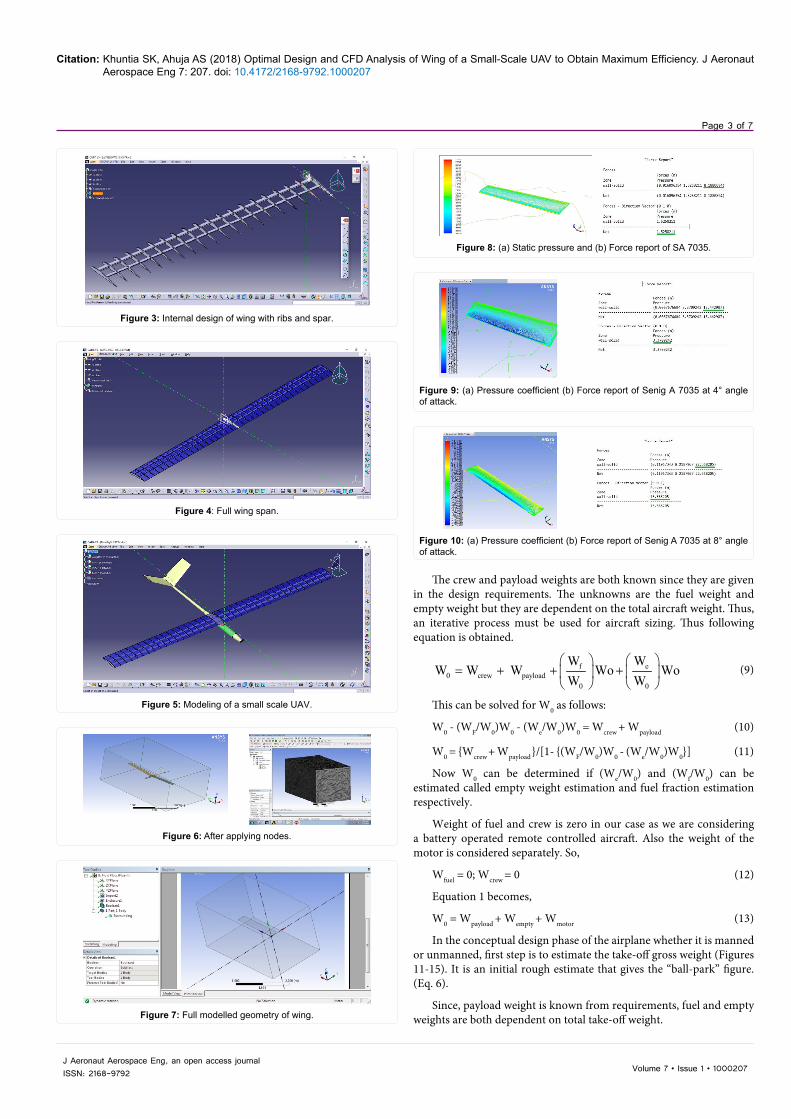
Figure 3: Internal design of wing with ribs and spar.
Figure 4: Full wing span.
Figure 5: Modeling of a small scale UAV.
Figure 6: After applying nodes.
Figure 7: Full modelled geometry of wing.
Figure 8: (a) Static pressure and (b) Force report of SA 7035.
Figure 9: (a) Pressure coefficient (b) Force report of Senig A 7035 at 4° angle of attack.
Figure 10: (a) Pressure coefficient (b) Force report of Senig A 7035 at 8° angle of attack.

Citation: Khuntia SK, Ahuja AS (2018) Optimal Design and CFD Analysis of Wing of a Small-Scale UAV to Obtain Maximum Efficiency. J Aeronaut Aerospace Eng 7: 207. doi: 10.4172/2168-9792.1000207
Page 4 of 7
Volume 7 • Issue 1 • 1000207J Aeronaut Aerospace Eng, an open access journalISSN: 2168-9792
Therefore the equation becomes:
0W1
payload
EmptyMotor
Guess Guess
WWW
W W
=− − (14)
Considering the following weights as rough estimates based on the various small scale UAVs available:
Rough weights of components: From the above Table 1,
WMotor = 350 grams and WEmpty = 2600 grams.
The WGuess can be any weight for the calculation purpose.
Substituting all the values in equation 6.6, we get:
(a) First estimate: Consider WGuess = 3010 grams, so W0 becomes
0350W 7525 grams
350 260013010 3010
= =− −
(b) Second estimate: Consider WGuess = 3030 grams, so W0 becomes
0350W 5681 grams
350 260013030 3030
= =− −
(c) Third estimate: Consider WGuess = 3050 grams, so W0 becomes
0350W 4575 grams
350 260013050 3050
= =− −
(d) Fourth estimate: Consider WGuess = 3080 grams, so W0 becomes
0350W 3553.846 grams
350 260013080 3080
= =− −
(e) Fifth estimate: Consider WGuess = 3095 grams, so W0 becomes
0350W 3201 grams
350 260013095 3095
= =− −
(f) Sixth estimate: Consider WGuess = 3100 grams, so W0 becomes
0350W 3100 grams
350 260013100 3100
= =− −
So it is estimated that the gross take-off weight of the aircraft would be about 3100 grams.
Air-foil selection
Initially three airfoils viz., Clark Y, Senig-Donovan 7032 and Senig-
Figure 11: (a) Pressure coefficient (b) Force report of Senig A 7035 at 12° angle of attack.
Figure 12: (a) Pressure coefficient (b) Force report of Senig A 7035 at 16° angle of attack.
Figure 13: Flow density over wing.
Figure 14: Total pressure coefficient.
Figure 15: Turbulent velocity over wing.
S. No Description Weights (Grams)1 Motor 3502 Payload 1503 Propeller 304 Servos 1205 First person view camera 506 Telemetry 307 Structure 20008 Battery 370
Table 1: Rough estimate of UAV parts.

Citation: Khuntia SK, Ahuja AS (2018) Optimal Design and CFD Analysis of Wing of a Small-Scale UAV to Obtain Maximum Efficiency. J Aeronaut Aerospace Eng 7: 207. doi: 10.4172/2168-9792.1000207
Page 5 of 7
Volume 7 • Issue 1 • 1000207J Aeronaut Aerospace Eng, an open access journalISSN: 2168-9792
Ashok Gopalaratnam (SA) 7035 were considered for flow analysis using ANSYS software to find out lift and drag produced by them at 20m/s and SA 7035 was the best choice due to its high lift and low drag as compared to other options . This airfoil was finalized for the UAV. A rectangular mono wing with high wing mounts of a span 04 metres and chord length of 0.3 metres was selected. The other characteristics of SD 7035 are as follows:-
(a) Aspect ratio: 4 13.340.3
bs
= =
Cl max of airfoil is 1.4
(b) Stall speed: 2 2 6.83 9.8 ft / sec0.0765 13.13 1.4l max
W * ñ S C * ft *
= =
(c) Take off speed: 2 2 6.831.2 1 .2 11.8ft / sec0.076 13.13 1.4l max
W * ñ S C * *
= =
(d) Load factor: ( )( )
2
2
1.15 0.9stall l max
stall l max
* *V * S * * C
* V * S * C
ρ
ρ
( )( )
2
2
0.0765 1.15 9.8 13.13 0.9 1.41.19
0.076 9.8 13.13 1.4
* * * * *
* * *= =
(e) Velocity during flare: 1.15∗Vstall = 12.054 ft/sec
(f) Touch down velocity: 1.23∗Vstall = 11.27 ft/sec.
Note: Dry air has a density of 0.076 lb/ft3, S = Wing Area = 13.13 ft2
CFD analysis
CFD is the art of replacing the differential equation governing the Fluid Flow, with a set of algebraic equations (the process is called discretization), which in turn can be solved with the aid of a digital computer to get an approximate solution. After importing UAV components into Ansys we define the analysis types by applying loads and initial conditions for the finite element solution. During mesh generation loading boundary conditions of inlet outlet wall and symmetry conditions are then applied to this elements and nodes of the UAV wing structure. For simulation of fluid flow analysis the UAV model was transferred to CFX/ FLUENT pre-processor. In this process details for fluid and solid domains were assigned. Material used for fluid type domain in our case is air at 250 C. Inlet and outlet details in fluid and Boundary Conditions were applied prior flow analysis we obtain the pressure counter and velocity streamline of fluid flow (Figures 16-20).
Grid generation
The sub- division of the flow domain into a number of smaller, non-overlapping sub-domains is the concept behind Grid generation. Accuracy of a solution, calculation time and cost in terms of necessary computer hardware are dependent on the fineness of the grid. Over 50% of time spent in industry on a CFD project is devoted to the definition of domain geometry and grid generation.
Flow analysis of wing
One of the most important criteria for any aircraft design is airfoil selection for its major lift producing surface called main plane or wing. The three airfoils viz., Clark Y, SD7032 and SA7035 were studied in ANSYS for the lift and drag at 20 m/s. The best results for Lift and Drag were that of SA7035. The Static pressure and the force reports are as follows
SA7035 was found to have the highest lift and lowest drag among the three, so this airfoil was finalized for the UAV. The wing was again studied for various flow parameters at different angles of attack and structural loads. The critical values were studied for setting up a safe flying envelope.
Figure 16: Force report of SA 7035 with a dihedral angle 3.50 and 0° angle of attack.
Figure 17: Force report of SA 7035 with a taper ratio of 0.5 and 0° angle of attack.
Figure 18: Stress intensity over wing.
Figure 19: Directional deformation of wing under stress.
Figure 20: Strain energy.
Citation: Khuntia SK, Ahuja AS (2018) Optimal Design and CFD Analysis of Wing of a Small-Scale UAV to Obtain Maximum Efficiency. J Aeronaut Aerospace Eng 7: 207. doi: 10.4172/2168-9792.1000207
Page 6 of 7
Volume 7 • Issue 1 • 1000207J Aeronaut Aerospace Eng, an open access journalISSN: 2168-9792
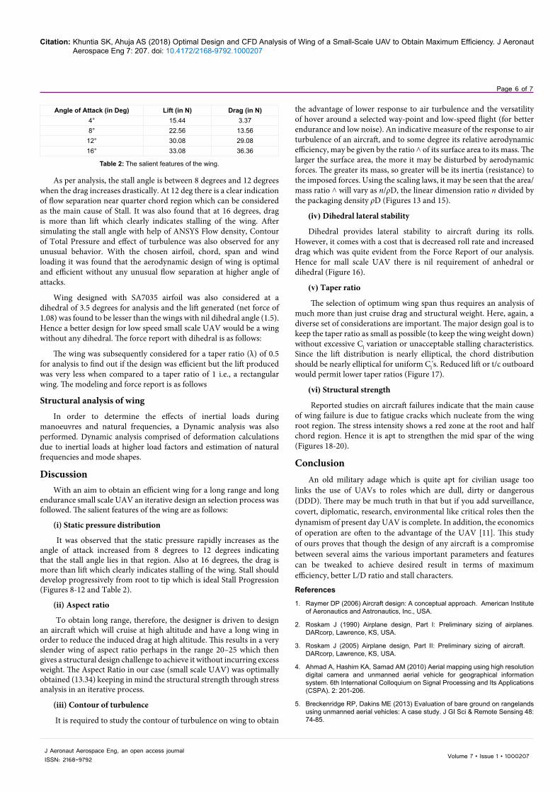
As per analysis, the stall angle is between 8 degrees and 12 degrees when the drag increases drastically. At 12 deg there is a clear indication of flow separation near quarter chord region which can be considered as the main cause of Stall. It was also found that at 16 degrees, drag is more than lift which clearly indicates stalling of the wing. After simulating the stall angle with help of ANSYS Flow density, Contour of Total Pressure and effect of turbulence was also observed for any unusual behavior. With the chosen airfoil, chord, span and wind loading it was found that the aerodynamic design of wing is optimal and efficient without any unusual flow separation at higher angle of attacks.
Wing designed with SA7035 airfoil was also considered at a dihedral of 3.5 degrees for analysis and the lift generated (net force of 1.08) was found to be lesser than the wings with nil dihedral angle (1.5). Hence a better design for low speed small scale UAV would be a wing without any dihedral. The force report with dihedral is as follows:
The wing was subsequently considered for a taper ratio (λ) of 0.5 for analysis to find out if the design was efficient but the lift produced was very less when compared to a taper ratio of 1 i.e., a rectangular wing. The modeling and force report is as follows
Structural analysis of wing
In order to determine the effects of inertial loads during manoeuvres and natural frequencies, a Dynamic analysis was also performed. Dynamic analysis comprised of deformation calculations due to inertial loads at higher load factors and estimation of natural frequencies and mode shapes.
DiscussionWith an aim to obtain an efficient wing for a long range and long
endurance small scale UAV an iterative design an selection process was followed. The salient features of the wing are as follows:
(i) Static pressure distribution
It was observed that the static pressure rapidly increases as the angle of attack increased from 8 degrees to 12 degrees indicating that the stall angle lies in that region. Also at 16 degrees, the drag is more than lift which clearly indicates stalling of the wing. Stall should develop progressively from root to tip which is ideal Stall Progression (Figures 8-12 and Table 2).
(ii) Aspect ratio
To obtain long range, therefore, the designer is driven to design an aircraft which will cruise at high altitude and have a long wing in order to reduce the induced drag at high altitude. This results in a very slender wing of aspect ratio perhaps in the range 20–25 which then gives a structural design challenge to achieve it without incurring excess weight. The Aspect Ratio in our case (small scale UAV) was optimally obtained (13.34) keeping in mind the structural strength through stress analysis in an iterative process.
(iii) Contour of turbulence
It is required to study the contour of turbulence on wing to obtain
the advantage of lower response to air turbulence and the versatility of hover around a selected way-point and low-speed flight (for better endurance and low noise). An indicative measure of the response to air turbulence of an aircraft, and to some degree its relative aerodynamic efficiency, may be given by the ratio ˄ of its surface area to its mass. The larger the surface area, the more it may be disturbed by aerodynamic forces. The greater its mass, so greater will be its inertia (resistance) to the imposed forces. Using the scaling laws, it may be seen that the area/mass ratio ˄ will vary as n/ρD, the linear dimension ratio n divided by the packaging density ρD (Figures 13 and 15).
(iv) Dihedral lateral stability
Dihedral provides lateral stability to aircraft during its rolls. However, it comes with a cost that is decreased roll rate and increased drag which was quite evident from the Force Report of our analysis. Hence for mall scale UAV there is nil requirement of anhedral or dihedral (Figure 16).
(v) Taper ratio
The selection of optimum wing span thus requires an analysis of much more than just cruise drag and structural weight. Here, again, a diverse set of considerations are important. The major design goal is to keep the taper ratio as small as possible (to keep the wing weight down) without excessive Cl variation or unacceptable stalling characteristics. Since the lift distribution is nearly elliptical, the chord distribution should be nearly elliptical for uniform Cl's. Reduced lift or t/c outboard would permit lower taper ratios (Figure 17).
(vi) Structural strength
Reported studies on aircraft failures indicate that the main cause of wing failure is due to fatigue cracks which nucleate from the wing root region. The stress intensity shows a red zone at the root and half chord region. Hence it is apt to strengthen the mid spar of the wing (Figures 18-20).
ConclusionAn old military adage which is quite apt for civilian usage too
links the use of UAVs to roles which are dull, dirty or dangerous (DDD). There may be much truth in that but if you add surveillance, covert, diplomatic, research, environmental like critical roles then the dynamism of present day UAV is complete. In addition, the economics of operation are often to the advantage of the UAV [11]. This study of ours proves that though the design of any aircraft is a compromise between several aims the various important parameters and features can be tweaked to achieve desired result in terms of maximum efficiency, better L/D ratio and stall characters.
References
1. Raymer DP (2006) Aircraft design: A conceptual approach. American Institute of Aeronautics and Astronautics, Inc., USA.
2. Roskam J (1990) Airplane design, Part I: Preliminary sizing of airplanes. DARcorp, Lawrence, KS, USA.
3. Roskam J (2005) Airplane design, Part II: Preliminary sizing of aircraft. DARcorp, Lawrence, KS, USA.
4. Ahmad A, Hashim KA, Samad AM (2010) Aerial mapping using high resolution digital camera and unmanned aerial vehicle for geographical information system. 6th International Colloquium on Signal Processing and Its Applications (CSPA). 2: 201-206.
5. Breckenridge RP, Dakins ME (2013) Evaluation of bare ground on rangelands using unmanned aerial vehicles: A case study. J GI Sci & Remote Sensing 48: 74-85.
Angle of Attack (in Deg) Lift (in N) Drag (in N)4° 15.44 3.378° 22.56 13.56
12° 30.08 29.0816° 33.08 36.36
Table 2: The salient features of the wing.
Citation: Khuntia SK, Ahuja AS (2018) Optimal Design and CFD Analysis of Wing of a Small-Scale UAV to Obtain Maximum Efficiency. J Aeronaut Aerospace Eng 7: 207. doi: 10.4172/2168-9792.1000207
Page 7 of 7
Volume 7 • Issue 1 • 1000207J Aeronaut Aerospace Eng, an open access journalISSN: 2168-9792
6. Theja RB, Gupta SM (2013) Design and fluid flow analysis of unmanned aerial vehicle (UAV).
7. Hoffmam KA, Chiang ST (2000) Computational fluid dynamics. A Publication of Engineering Education System. Wichita, Kansas, USA.
8. ANSYS (2000) – Fluent Training Material.
9. Anderson JD (2000) Computational fluid dynamics: The basics with applications. McGraw-Hill series, NY, USA.
10. Lyon CA, Broeren AP, Gigu`ere P, Gopalarathnam A, Selig MS (1995) Summary of low-speed airfoil data. SoarTech Publications, Virginia, USA.
11. Austin R (2010) Unmanned Aircraft Systems, UAVs design, development and deployment: Aerospace Series. Wiley Publishers, NY, USA.