a visual programming environment for authoring asd therapy tools
TRANSCRIPT

A Visual Programming Environment for AuthoringASD Therapy Tools
by
Mwawi Fred Msiska
Thesis presented in partial fulfilment of the requirementsfor the degree of Master of Science in Computer Science at
Stellenbosch University
Supervisor: Prof. L van Zijl
September 2011

Declaration
By submitting this thesis electronically, I declare that the entirety of the work con-tained therein is my own, original work, that I am the owner of the copyright thereof(unless to the extent explicitly otherwise stated) and that I have not previously inits entirety or in part submitted it for obtaining any qualification.
Signature: . . . . . . . . . . . . . . . . . . . . . . . . . . . . .M.F. Msiska
2011/09/13Date: . . . . . . . . . . . . . . . . . . . . . . . . . . . . . . . . .
Copyright c© 2011 Stellenbosch UniversityAll rights reserved.
i

Abstract
3D virtual environments can be used as therapy tools in patients with autism spec-trum disorders (ASDs); however, the development of such tools is time-consuming.A 3D virtual environment development platform for such tools has been developedspecifically for the South African context, because of the language and culturesensitivity of these therapy tools.
The 3D virtual environment development platform has a Lua scripting interfacefor specifying logic in the virtual environments. Lua is a textual programminglanguage, and presents a challenge to ASDs therapists’ ability to create therapytools without engaging an expert programmer.
The aim of this research was to investigate the design and implementation of avisual programming environment to support non-expert programmers in scriptingwithin the 3D virtual environment development platform.
Various visual program representation techniques, reported in literature, were ex-amined to determine their appropriateness for adoption in our design. A visualprogramming language based on the “building-block” approach was considered themost suitable. The research resulted in the development of a visual script editor(VSE), based on an open source framework called the OpenBlocks library.
The VSE successfully alleviated the syntax burden that textual programming lan-guages place on non-expert programmers. The fitness of purpose of our VSE wasexemplified in a sample 3D virtual environment that was scripted using the VSE.Despite the success, we argue that the applicability of the “building-block” ap-proach is limited to domain-specific programming languages due to the absence ofvisual expressions for defining user-defined types, and for specifying hierarchy.
ii

Acknowledgements
I owe my deepest gratitude to my supervisor, Prof. Lynette van Zijl, for her support,mentorship and patience throughout the research work that culminated into thisthesis.
I would also like to thank Daniel Wendel for providing useful information on theOpenBlocks library. This information was crucial to the understanding of theOpenBlocks API.
Finally, it is also an honour for me to thank the following people: my parents fortheir encouragement and their undying faith in me; my wife, Grace, for her under-standing and encouragement during the research; and my daughter, Sangwani, forsacrificing daddy’s attention.
iii

Contents
Declaration i
Abstract ii
Acknowledgements iii
Contents iv
List of Figures vii
1 Introduction 11.1 Background . . . . . . . . . . . . . . . . . . . . . . . . . . . . . . . 11.2 Research Objective . . . . . . . . . . . . . . . . . . . . . . . . . . . 21.3 Motivation . . . . . . . . . . . . . . . . . . . . . . . . . . . . . . . . 31.4 Approach . . . . . . . . . . . . . . . . . . . . . . . . . . . . . . . . 31.5 Terminological Note . . . . . . . . . . . . . . . . . . . . . . . . . . 41.6 Thesis Outline . . . . . . . . . . . . . . . . . . . . . . . . . . . . . . 4
2 Literature Survey 52.1 Overview of Visual Programming . . . . . . . . . . . . . . . . . . . 52.2 Visual Program Representation Techniques . . . . . . . . . . . . . . 8
2.2.1 Form-based and Spreadsheet Languages . . . . . . . . . . . 92.2.2 Dataflow Languages . . . . . . . . . . . . . . . . . . . . . . 102.2.3 Iconic Languages . . . . . . . . . . . . . . . . . . . . . . . . 112.2.4 Programming by Demonstration . . . . . . . . . . . . . . . . 192.2.5 Building-block Programming . . . . . . . . . . . . . . . . . . 202.2.6 Discussion . . . . . . . . . . . . . . . . . . . . . . . . . . . . 21
iv

2.3 Related Visual Game Generators . . . . . . . . . . . . . . . . . . . 252.3.1 Scratch . . . . . . . . . . . . . . . . . . . . . . . . . . . . . 262.3.2 Alice . . . . . . . . . . . . . . . . . . . . . . . . . . . . . . . 292.3.3 StarLogo TNG . . . . . . . . . . . . . . . . . . . . . . . . . 33
2.4 Chapter Summary . . . . . . . . . . . . . . . . . . . . . . . . . . . 33
3 The VSE Programming Environment 353.1 The Game Production Process . . . . . . . . . . . . . . . . . . . . . 36
3.1.1 The Game Engine . . . . . . . . . . . . . . . . . . . . . . . . 363.1.2 3D Models and Scenes . . . . . . . . . . . . . . . . . . . . . 373.1.3 Graphical User Interface . . . . . . . . . . . . . . . . . . . . 373.1.4 The Lua Scripting Challenges . . . . . . . . . . . . . . . . . 38
3.2 Design Objectives . . . . . . . . . . . . . . . . . . . . . . . . . . . . 393.3 The OpenBlocks Library . . . . . . . . . . . . . . . . . . . . . . . . 403.4 The Design of the VSE . . . . . . . . . . . . . . . . . . . . . . . . . 45
3.4.1 Extensions to the OpenBlocks Library . . . . . . . . . . . . 463.4.2 Managing Scenes . . . . . . . . . . . . . . . . . . . . . . . . 503.4.3 Managing Game GUI . . . . . . . . . . . . . . . . . . . . . . 533.4.4 Managing Game Configuration . . . . . . . . . . . . . . . . 543.4.5 The Code Generator . . . . . . . . . . . . . . . . . . . . . . 553.4.6 Persistent Storage of Visual Programs . . . . . . . . . . . . 63
3.5 Chapter Summary . . . . . . . . . . . . . . . . . . . . . . . . . . . 65
4 Example of Usage: Journey to the Moon 674.1 Introduction . . . . . . . . . . . . . . . . . . . . . . . . . . . . . . . 674.2 The Goals of Testing . . . . . . . . . . . . . . . . . . . . . . . . . . 694.3 Testing Strategy . . . . . . . . . . . . . . . . . . . . . . . . . . . . . 704.4 Observations . . . . . . . . . . . . . . . . . . . . . . . . . . . . . . . 74
4.4.1 Literal Constants . . . . . . . . . . . . . . . . . . . . . . . . 744.4.2 Block-to-Function Mapping . . . . . . . . . . . . . . . . . . 754.4.3 Variables and Connector Shapes . . . . . . . . . . . . . . . . 774.4.4 GUIs and Memory . . . . . . . . . . . . . . . . . . . . . . . 784.4.5 Routine Tasks . . . . . . . . . . . . . . . . . . . . . . . . . . 80
4.5 Chapter Summary . . . . . . . . . . . . . . . . . . . . . . . . . . . 81

5 Results and Conclusions 825.1 The VSE and the Research Objective . . . . . . . . . . . . . . . . . 82
5.1.1 Elimination of the Syntax Burden . . . . . . . . . . . . . . . 825.1.2 Hidden Technical Jargon . . . . . . . . . . . . . . . . . . . . 845.1.3 Provision of Task-Oriented Library Functions . . . . . . . . 855.1.4 Static Typing . . . . . . . . . . . . . . . . . . . . . . . . . . 855.1.5 Automatic Discovery of Programmable Elements . . . . . . . 865.1.6 Resource File Management . . . . . . . . . . . . . . . . . . . 875.1.7 Extensibility . . . . . . . . . . . . . . . . . . . . . . . . . . . 87
5.2 Limitations of the Building Block Approach . . . . . . . . . . . . . 885.2.1 Lack of Hierarchy . . . . . . . . . . . . . . . . . . . . . . . . 885.2.2 Connector Shapes . . . . . . . . . . . . . . . . . . . . . . . . 895.2.3 Variable Scoping . . . . . . . . . . . . . . . . . . . . . . . . 90
5.3 Future Work . . . . . . . . . . . . . . . . . . . . . . . . . . . . . . . 915.3.1 Global Variables . . . . . . . . . . . . . . . . . . . . . . . . 925.3.2 Page Variables . . . . . . . . . . . . . . . . . . . . . . . . . 925.3.3 Local Variables . . . . . . . . . . . . . . . . . . . . . . . . . 93
5.4 Conclusion . . . . . . . . . . . . . . . . . . . . . . . . . . . . . . . . 94
Appendices 96
A A DTD for the VSE’s Language Definition XML File 97
B A DTD for the VSE’s Project XML Files 102
C A DTD for the VSE’s Main XML Files 103
D A DTD for the VSE’s XML Files for Saving Scene Blocks 104
E A DTD for the VSE’s XML Files for Saving GUI Blocks 107
Bibliography 109
List of Figures
2.1 Switch and Merge nodes (adapted from [38], page 4) . . . . . . . . . . 112.2 A screenshot from Stagecast Creator [8] showing a graphical rewrite rule 132.3 A screenshot from Stagecast Creator [8] showing the subtleness of a
“move left” rule . . . . . . . . . . . . . . . . . . . . . . . . . . . . . . . 142.4 Screenshots from Stagecast Creator [8] showing context sensitivity of
graphical rewrite rules . . . . . . . . . . . . . . . . . . . . . . . . . . . 152.5 An example of a comic strip iconic sentence (adapted from [40], page 113) 162.6 Rule involving objects at different locations (reprinted from [40], page
114) . . . . . . . . . . . . . . . . . . . . . . . . . . . . . . . . . . . . . 172.7 The use of an inner panel to express spatial separation (reprinted from [40],
page 114) . . . . . . . . . . . . . . . . . . . . . . . . . . . . . . . . . . 182.8 A keyboard rule (reprinted from [40], page 115) . . . . . . . . . . . . . 182.9 A rule involving system clock (reprinted from [40], page 115) . . . . . . 192.10 Tiles from Scratch [7] . . . . . . . . . . . . . . . . . . . . . . . . . . . . 202.11 A screenshot from Scratch [7] showing the main window . . . . . . . . 262.12 Scratch’s event blocks . . . . . . . . . . . . . . . . . . . . . . . . . . . 272.13 Concurrency in Scratch . . . . . . . . . . . . . . . . . . . . . . . . . . . 272.14 A syntax error in Scratch: an attempt to multiply a number and a string 292.15 The syntax error in Figure 2.14 treated as a runtime error by Scratch . 292.16 A screenshot from Alice [2] showing the main window . . . . . . . . . . 302.17 Alice blocks’ lack of differentiated shape outlines . . . . . . . . . . . . . 32
3.1 A screenshot from StarLogo TNG [4] showing the StarLogoBlocks VPE 413.2 Screenshots from StarLogo TNG showing code folding . . . . . . . . . 443.3 The VSE system overview . . . . . . . . . . . . . . . . . . . . . . . . . 45
vii
LIST OF FIGURES viii
3.4 Confusion emanating from overloaded connector shapes (adapted from [54],page 30) . . . . . . . . . . . . . . . . . . . . . . . . . . . . . . . . . . . 47
3.5 An obvious error caused by allowing strings to refer to objects . . . . . 473.6 A floating-point number used to index a list . . . . . . . . . . . . . . . 493.7 A stack of blocks . . . . . . . . . . . . . . . . . . . . . . . . . . . . . . 563.8 An internal representation of the stack of blocks in Figure 3.7 . . . . . 563.9 An abstract syntax tree extracted from Figure 3.8 . . . . . . . . . . . . 573.10 Files of a VSE program . . . . . . . . . . . . . . . . . . . . . . . . . . 64
4.1 A screenshot from Journey to the Moon (adapted from [61], page 90) . 684.2 Wrapping blocks under test in a procedure to detect syntax errors . . . 714.3 Screenshot from the VSE showing a form for marking scene objects as
programmable or non-programmable . . . . . . . . . . . . . . . . . . . 734.4 Blocks for loading and translating educational content . . . . . . . . . 744.5 Adding an entry to log entity . . . . . . . . . . . . . . . . . . . . . . . 764.6 Block for retrieving or creating a log entity . . . . . . . . . . . . . . . . 774.7 The equivalent of the code in Figure 4.6 in the absence of log entity
variables . . . . . . . . . . . . . . . . . . . . . . . . . . . . . . . . . . . 784.8 GUI widget blocks in a drawer and part of a GUI script . . . . . . . . 794.9 Modified project organization . . . . . . . . . . . . . . . . . . . . . . . 80
5.1 VSE’s version of the move forward statement . . . . . . . . . . . . . . 855.2 A screenshot from the VSE showing a logical error emanating from the
lack of mechanisms to control the scope of formal parameters . . . . . . 915.3 Page variables . . . . . . . . . . . . . . . . . . . . . . . . . . . . . . . . 925.4 A local variable scope-delimiting block . . . . . . . . . . . . . . . . . . 935.5 A local variable scope-delimiting procedure block . . . . . . . . . . . . 945.6 Nested scope-delimiting blocks . . . . . . . . . . . . . . . . . . . . . . . 94

Chapter 1
Introduction
This thesis investigates the design and implementation of a visual programmingenvironment for authoring 3D virtual environments that can be used as learningaids; and as ASDs therapy tools. The visual programming environment is neces-sitated by the desire to enable ASDs therapists to build therapy tools, since theyare endowed with domain knowledge. The research has led to the development ofthe visual script editor (VSE), a prototype system for graphical programming ofvirtual environments.
1.1 Background
Newschaffer et al [50] define autism spectrum disorders (ASDs) as “a group ofneurodevelopmental disorders characterized by core deficits in three domains: socialinteraction, communication, and repetitive or stereotypic behaviour.” Prevalencerates as high as 110 per 10000 have been reported in literature [18, 42].
The use of computerised tools has been shown to have great potential in mitigatingthe learning difficulties associated with people with ASDs [30, 48]. Virtual environ-ments (VEs), in particular, are among the most promising in this regard [51, 52, 56].Chamberlain [61] argues that computerised ASDs therapy tools have language andcultural dependencies; and consequently, motivates the need for a tool to supportthe development of therapy tools specific to the South African context.
The work documented in this thesis is part of the broader ASD Assist project at
1
CHAPTER 1. INTRODUCTION 2
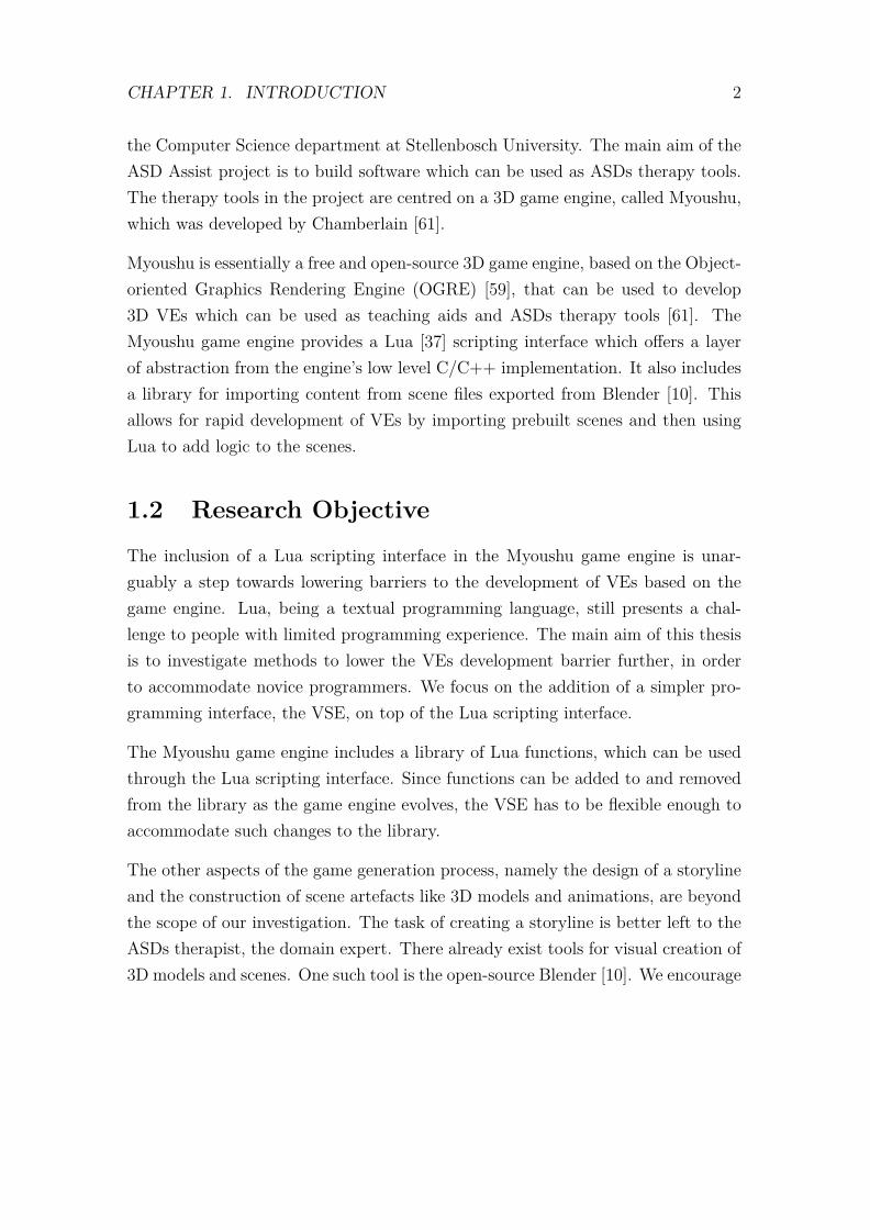
the Computer Science department at Stellenbosch University. The main aim of theASD Assist project is to build software which can be used as ASDs therapy tools.The therapy tools in the project are centred on a 3D game engine, called Myoushu,which was developed by Chamberlain [61].
Myoushu is essentially a free and open-source 3D game engine, based on the Object-oriented Graphics Rendering Engine (OGRE) [59], that can be used to develop3D VEs which can be used as teaching aids and ASDs therapy tools [61]. TheMyoushu game engine provides a Lua [37] scripting interface which offers a layerof abstraction from the engine’s low level C/C++ implementation. It also includesa library for importing content from scene files exported from Blender [10]. Thisallows for rapid development of VEs by importing prebuilt scenes and then usingLua to add logic to the scenes.
1.2 Research Objective
The inclusion of a Lua scripting interface in the Myoushu game engine is unar-guably a step towards lowering barriers to the development of VEs based on thegame engine. Lua, being a textual programming language, still presents a chal-lenge to people with limited programming experience. The main aim of this thesisis to investigate methods to lower the VEs development barrier further, in orderto accommodate novice programmers. We focus on the addition of a simpler pro-gramming interface, the VSE, on top of the Lua scripting interface.
The Myoushu game engine includes a library of Lua functions, which can be usedthrough the Lua scripting interface. Since functions can be added to and removedfrom the library as the game engine evolves, the VSE has to be flexible enough toaccommodate such changes to the library.
The other aspects of the game generation process, namely the design of a storylineand the construction of scene artefacts like 3D models and animations, are beyondthe scope of our investigation. The task of creating a storyline is better left to theASDs therapist, the domain expert. There already exist tools for visual creation of3D models and scenes. One such tool is the open-source Blender [10]. We encourage

CHAPTER 1. INTRODUCTION 3
its use because the Myoushu game engine is capable of importing scenes exportedfrom Blender.
1.3 Motivation
The development of VEs is time consuming [61] and expensive; and furthermore,if the VEs are to be used for ASDs therapy, then there is need for the VEs to beadapted to the specific needs of each individual patient. To cut the developmenttime and budget for the ASDs therapy tools, we propose that a repository of VEartefacts1 be made available; and then give the responsibility of authoring the finaltherapy tools to the therapist. Since the therapist may not be a programmer (andshould not be forced to become one), there is need to simplify the scripting interface.
We do not replace the Lua programming interface in the Myoushu game engine withthe VSE; rather, the VSE translates the graphical programs into Lua. This setupnot only takes the burden of the final object code optimisation from the VSE, butalso affords the possibility for expert Lua programmers to textually edit programs,created by non-Lua programmers, in order to add advanced features to the VEs.
1.4 Approach
In the pursuit of the research objective, various possibilities are considered; fromfully-fledged visual programming languages to simple game creation tools. Thisinvestigation guides the formulation of constraints on the VSE, which include: thetype of visual programming language to use; the extent to which the visual pro-gramming paradigm is used; and the appropriate level of abstraction.
Roque [54] states that the development of a graphical programming environmentis time consuming. Because of this, and the limited time frame in which the thesishad to be completed, we explore the prospect of extending an existing open-sourceframework in constructing our prototype graphical programming environment. TheOpenBlocks [54] framework is adopted, and is discussed further in Chapter 3.
1Examples of which include 3D models and prebuilt scenes (without logic).
CHAPTER 1. INTRODUCTION 4
We build on the OpenBlocks framework and realize our visual programming lan-guage, which forms the basis of the VSE. The visual programming language isdesigned to mirror traditional textual programming languages in the sense of hav-ing a fixed core; and being extendable through the addition of third party libraries.
The use of OpenBlocks also enables us to quickly evaluate different visual elementdesigns using traditional user interface evaluation techniques.
1.5 Terminological Note
In this thesis, we use the words program and script interchangeably to mean asimple program spanning no more than a thousand lines of source instructions. Inthe same vein, the words programming and scripting are used interchangeably.
We also use the words user, programmer and the phrase “novice programmer” tomean a person with limited or no programming experience, for whom the VSE isintended.
1.6 Thesis Outline
The rest of this thesis is organized as follows: Chapter 2 presents an overview ofvisual programming; and its applicability to the problem investigated in this thesis.Several approaches to visual programming are explored; and suitability for adoptionin our VSE is examined. We then look at existing visual VE authoring tools thatinspired our work. The design and implementation of the VSE is described inChapter 3. Chapter 4 discusses the creation of scripts, for an educational game,using the VSE to demonstrate its capabilities. Chapter 5 discusses the extent towhich the research objective, outlined in Section 1.2, is met. We also discuss theshortfalls of the VSE and suggest remedies. The chapter ends with a summary ofgeneral conclusions drawn from the research.

Chapter 2
Literature Survey
There is a plethora of literature on visual programming languages and systems. Ourinvestigation focused on the identification of the available options regarding visualrepresentation of programs. We therefore do not expend much effort in describingindividual visual programming languages or systems in detail; rather, we identifyand discuss categories of visual program representation techniques.
The chapter begins with a description of the visual programming paradigm; andthe relationship between a visual programming language (VPL) and a visual pro-gramming environment (VPE), in Section 2.1. The section also discusses the goalsof the visual programming concept; and the strategies that can be used to real-ize these goals. Section 2.2 presents a summary of visual program representationtechniques that have been reported in literature. We conclude Section 2.2 with abrief discussion on the suitability of each technique as a solution to our problem.Section 2.3 discusses three examples of VPEs, for authoring games, whose visualrepresentation technique is similar to the one adopted in the VSE. We end thechapter with a chapter summary in Section 2.4.
2.1 Overview of Visual Programming
Visual programming is programming in which semantics is expressed using morethan one dimension [22, 49]. Textual programming is considered one-dimensionalin the sense that a program is composed of only linear strings. Typing the pro-
5

CHAPTER 2. LITERATURE SURVEY 6
gram statements or expressions on multiple lines does not introduce an additionaldimension since no additional semantics are implied by the line breaks [22].
A visual programming language (VPL) does not necessarily exclude the use of text.Text is permitted, but in a multidimensional context [22]. The only constrainton a VPL is that a significant portion of the semantics of the language should beexpressed in other dimensions. Text is still the most natural medium for expressingentities such as names of objects and numeric values.
Examples of the additional dimensions available to a visual programming languageinclude: 2D or 3D images, which can be used to represent an entity, an expression ora command; relative positions among objects can be used to represent relationshipsamong entities, expressions and commands; and the dimension of time can be usedto specify the chronological order of events in the programming by demonstrationapproach.
The term VPL is reserved for multidimensional programming languages in whichthe visual expressions can be directly compiled (or interpreted) into executablebinary code, without first converting the visual program into a human-readable(and editable) textual programming language [22]. If the visual expressions are firstconverted into a traditional textual programming language before final compilation(or interpretation) into an executable binary, then the configuration is referred toas a visual programming environment (VPE).
Graphical user interface (GUI) builders like the ones used in Microsoft Visual Stu-dio [11] and NetBeans’ Swing GUI Builder [15] cannot be classified as VPEs. Insuch systems, the use of visual expressions is limited to the specification of staticGUIs. Thus only the compositional aspect of programming is used. The other twoaspects, namely selection and iteration, are not used; and consequently, these GUIbuilders are not programming languages.
Burnett [22] identifies the three major goals of VPL research, namely: “to makeprogramming more understandable to some particular audience”; to reduce humaneffort in ensuring syntactic correctness of programs; and to reduce program devel-opment time. Burnett [22] states that VPLs use the following four strategies inorder to achieve these goals:
CHAPTER 2. LITERATURE SURVEY 7
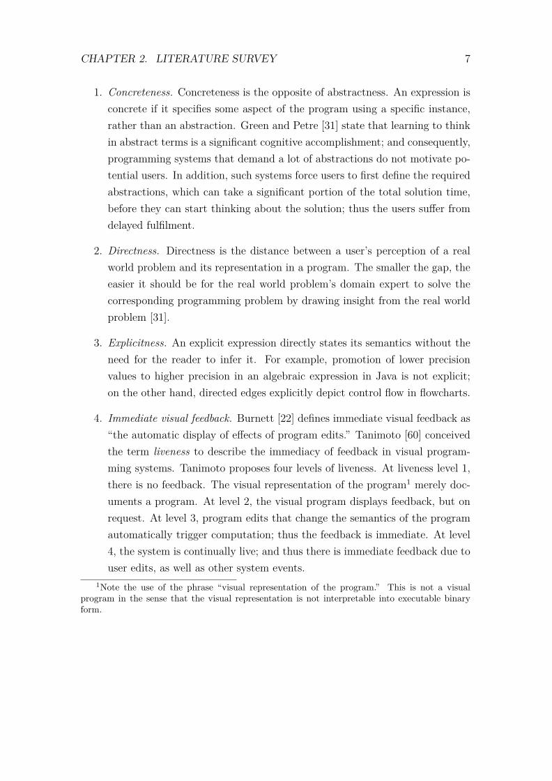
1. Concreteness. Concreteness is the opposite of abstractness. An expression isconcrete if it specifies some aspect of the program using a specific instance,rather than an abstraction. Green and Petre [31] state that learning to thinkin abstract terms is a significant cognitive accomplishment; and consequently,programming systems that demand a lot of abstractions do not motivate po-tential users. In addition, such systems force users to first define the requiredabstractions, which can take a significant portion of the total solution time,before they can start thinking about the solution; thus the users suffer fromdelayed fulfilment.
2. Directness. Directness is the distance between a user’s perception of a realworld problem and its representation in a program. The smaller the gap, theeasier it should be for the real world problem’s domain expert to solve thecorresponding programming problem by drawing insight from the real worldproblem [31].
3. Explicitness. An explicit expression directly states its semantics without theneed for the reader to infer it. For example, promotion of lower precisionvalues to higher precision in an algebraic expression in Java is not explicit;on the other hand, directed edges explicitly depict control flow in flowcharts.
4. Immediate visual feedback. Burnett [22] defines immediate visual feedback as“the automatic display of effects of program edits.” Tanimoto [60] conceivedthe term liveness to describe the immediacy of feedback in visual program-ming systems. Tanimoto proposes four levels of liveness. At liveness level 1,there is no feedback. The visual representation of the program1 merely doc-uments a program. At level 2, the visual program displays feedback, but onrequest. At level 3, program edits that change the semantics of the programautomatically trigger computation; thus the feedback is immediate. At level4, the system is continually live; and thus there is immediate feedback due touser edits, as well as other system events.
1Note the use of the phrase “visual representation of the program.” This is not a visualprogram in the sense that the visual representation is not interpretable into executable binaryform.
CHAPTER 2. LITERATURE SURVEY 8
The four strategies listed above are not always desirable in their entirety. Con-creteness and directness can sometimes be in conflict; and as such tradeoffs needto be adopted. For example, lowering the level of concreteness (increasing abstrac-tion) can result into improved directness [31]. Although liveness levels 3 and 4seem attractive, they are not critical unless the VPL is intended to be used in thecontext of a live system2 that is processing time-varying data [60]. Liveness level 2is therefore sufficient for our VSE.
2.2 Visual Program Representation Techniques
Our categorization of visual program representation techniques is primarily basedon the visual programming language classification system devised by Burnett andBaker [23]; and a classification of programming systems by specification style byMyers [49]. Burnett and Baker identify three broad subcategories under “visual rep-resentations” namely: diagrammatic languages, iconic languages, and languagesbased on static pictorial sequences. We found this classification of visual pro-gram representation techniques insufficient since form-based, spreadsheet-basedand demonstrational techniques would not fit under any subcategory. On the otherhand, certain categories in Myers’ classification could be collapsed into one; forexample, data-flow graphs and directed graphs are special cases of dataflow VPLs.
Our categorization takes the subcategories under “paradigms” in [23] and filters outthe subcategories which also apply to textual programming languages. Iconic andjigsaw puzzle pieces [49] languages are added to the remaining subcategories. Weverified the new categorization by ensuring that all categories (or subcategories),based on visual program representation, presented in both [23] and [49] are assignedto a category under our new categorization. The resulting five categories are:
1. Form-based and Spreadsheet Languages;
2. Dataflow Languages;
3. Iconic Languages;2A system that is running – its logic has to be updated without restarting it.

CHAPTER 2. LITERATURE SURVEY 9
4. Programming by Demonstration; and
5. Building-block Programming.
These categories are discussed in Sections 2.2.1 to 2.2.5.
2.2.1 Form-based and Spreadsheet Languages
Form-based VPLs express a program using a set of forms. A form is a uniquelyidentifiable set of cells. A cell is the smallest program unit; and can hold a value ora formula. A form-based computer language qualifies as a programming languageif it supports composition, selection and iteration. This requirement excludes theproperty sheets used in simple user interface builders (like the ones used in MicrosoftVisual Studio and NetBeans GUI Builder) from the category.
Form-based VPLs are the most basic form of visual programming languages [25].As the name suggests, form-based VPLs use the metaphor of a paper-based form.It is thus not surprising that all the examples that we found in literature expresstheir semantics declaratively.
Form-based languages have been grouped together with spreadsheet languages be-cause a spreadsheet, which is a tabular structure, can be considered a restrictedtype of a form [25]. In pure spreadsheet languages, all the cells on the form havethe same geometry; are arranged in a rectangular grid; and nested cells are notallowed. In addition, Rothermel et al [55] and Burnett et al [21, 24] report thatpure spreadsheets are constrained by Alan Kay’s value rule, which states that acell’s value is solely determined by the value or formula explicitly given to it by theuser [39].
One of the earliest examples of a form-based VPL is Query-By-Example [63]. TheVPL supports data definition and manipulation in a relational database. A query isbuilt by creating a skeleton table and filling it with an example solution. Examplesolutions are constructed using example elements3 and constant elements4. Thetwo types of elements are visually distinguished by underlining the latter. The
3A value that is not necessarily in the database.4A value that must be in the database.
CHAPTER 2. LITERATURE SURVEY 10
language is capable of visually expressing complex SQL queries involving multipletables.
Financial spreadsheet applications are also an example of form-based languages;however, most of them are not pure spreadsheet languages because of the use oftools such as macros which violate the value rule [24]. In financial spreadsheets, thetypical content of a cell is textual (including values and formulas that reference othercells), although graphics are used for data visualisation. Some spreadsheet VPLsaccept graphics as cell contents. Examples of such languages are Forms/3 [21, 24]and Penguims [34].
2.2.2 Dataflow Languages
Dataflow VPLs use a graphical representation of a dataflow execution model toexpress the semantics of a program. The graphical representation typically takesthe form of a directed graph in which nodes represent functions, and the edgesrepresent the flow of data [32, 38].
Johnston [38] describes a popular pure dataflow execution model called the token-based dataflow model. In this model, a node represents a function; and an edgerepresents the flow of a data token. The model does not specify any order of execu-tion; instead, a node becomes active when it receives a token from each incomingedge. Once a node is activated, it consumes the tokens; uses the tokens in its com-putation; and finally generates a set of new tokens which are placed on its outgoingedges. Each edge transfers at most one token at any given time. A node becomesinactive as soon as it places output tokens on its outgoing edges. An edge mayfork into several edges; and in such a case, a token flowing in the original edgeis duplicated such that each child edge carries a single copy of the original token.Several edges cannot, however, combine into one edge.
A pure token-based dataflow execution model explicitly supports (parallel) compo-sition; and iteration through cyclic directed graphs. The model does not explicitlysupport selection.
Johnston [38] describes an extension, the gates concept, to the pure dataflow modelthat can be used to explicitly express selection. There are two kinds of gates, the

CHAPTER 2. LITERATURE SURVEY 11
merge gate and the switch gate. The two gates are shown in Figure 2.1.
Figure 2.1: Switch and Merge nodes (adapted from [38], page 4)
The switch gate accepts a single token and a control token. The control token is aBoolean and can assume either of the values true or false. When the control tokenis true, the data token is propagated to the “true” outgoing edge; and when thecontrol token is false, the data token is propagated to the “false” outgoing edge.
The merge gate has a control incoming edge and two other incoming edges labelled“true” and “false.” When the control token is true, the data token on the “true”incoming edge is propagated to the outgoing edge; and when the control token isfalse, the data token on the “false” incoming edge is propagated to the outgoingedge.
Hils [32] presents a survey of dataflow VPLs. The VPLs surveyed range fromdomain-specific VPLs to general purpose VPLs.
2.2.3 Iconic Languages
An icon is a sign that resembles some world object. The icon and the world objectshare some common visual properties such shape and colour; however, the icon maybe an abstracted version of the real world object and some properties like size areusually different [40].

CHAPTER 2. LITERATURE SURVEY 12
Not all visual languages that use icons are iconic. A visual language is iconic if itexpresses semantics using iconic sentences. Myers [49] defines an iconic sentenceas a visual sentence that is composed of icons in which relative positions of iconsconvey additional semantics regardless of whether the icons are connected.
We identified two subcategories of iconic languages namely: graphical rewrite rulesand comic strip programming; which are briefly discussed in Sections 2.2.3.1 and2.2.3.2 respectively.
2.2.3.1 Graphical Rewrite Rules
Graphical rewrite rule systems typically have a grid of rectangular cells on whichicons can be placed. A statement in such a system takes the form of a before-afterrule. The before expression is an iconic sentence representing a situation (placementof runtime icons) that the processor can recognize at runtime. The after expressionis also an iconic sentence involving, among others, a subset of the icons in thebefore expression. New icons can be introduced in the after expression. The afterexpression is a runtime placement of icons that replaces the before placement whenthe processor recognizes the latter placement.
In graphical rewrite rule systems, an icon forming part of an iconic sentence refersto all instances of the same icon at runtime. This implies a high level of directness.It also implies a high level of directness since runtime icons are represented bysimilar icon instances in iconic sentences, rather than some abstraction.
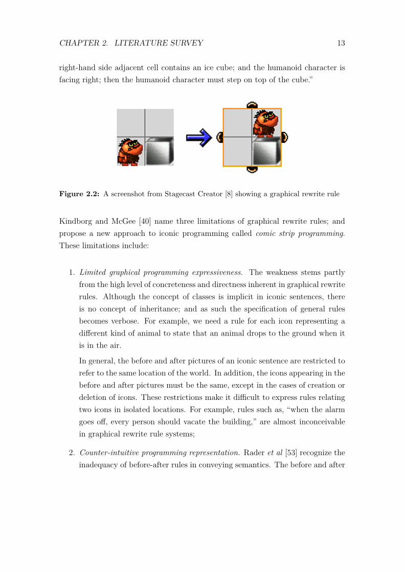
An example of a visual programming system that uses graphical rewrite rules isStagecast Creator [8].5 Figure 2.2 shows an example of Stagecast Creator’s graph-ical rewrite rules. The rule states that when the humanoid character is in a cellwhose right-hand side adjacent cell contains an ice cube, the humanoid charactermust step on top of the cube. In some cases, characters can have multiple ap-pearances6. In such cases, both relative position and appearance are meaningful.For example, if the humanoid character had multiple appearances, then the rule inFigure 2.2 would be interpreted as, “when the humanoid character is in a cell whose
5Stagecast Creator also uses programming by demonstration and form-based programming inaddition to the graphical rewrite rules.
6Each appearance is actually a different icon.
CHAPTER 2. LITERATURE SURVEY 13
right-hand side adjacent cell contains an ice cube; and the humanoid character isfacing right; then the humanoid character must step on top of the cube.”
Figure 2.2: A screenshot from Stagecast Creator [8] showing a graphical rewrite rule
Kindborg and McGee [40] name three limitations of graphical rewrite rules; andpropose a new approach to iconic programming called comic strip programming.These limitations include:
1. Limited graphical programming expressiveness. The weakness stems partlyfrom the high level of concreteness and directness inherent in graphical rewriterules. Although the concept of classes is implicit in iconic sentences, thereis no concept of inheritance; and as such the specification of general rulesbecomes verbose. For example, we need a rule for each icon representing adifferent kind of animal to state that an animal drops to the ground when itis in the air.
In general, the before and after pictures of an iconic sentence are restricted torefer to the same location of the world. In addition, the icons appearing in thebefore and after pictures must be the same, except in the cases of creation ordeletion of icons. These restrictions make it difficult to express rules relatingtwo icons in isolated locations. For example, rules such as, “when the alarmgoes off, every person should vacate the building,” are almost inconceivablein graphical rewrite rule systems;
2. Counter-intuitive programming representation. Rader et al [53] recognize theinadequacy of before-after rules in conveying semantics. The before and after
CHAPTER 2. LITERATURE SURVEY 14
pictures obfuscate the event that occurred in between. For example, no singleiconic sentence can represent a rule that says a dog standing next to a tableshould jump and land in the same location, and facing the same direction asbefore, since the before and after pictures would be exactly the same.
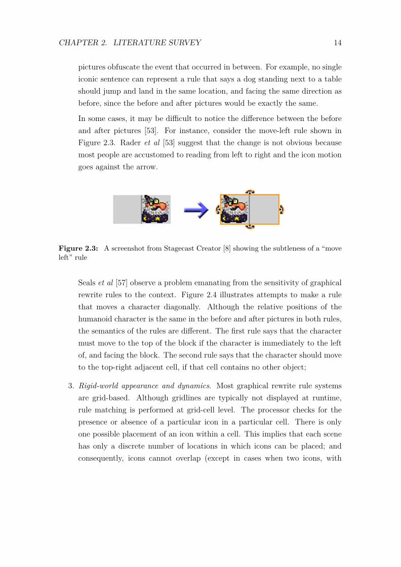
In some cases, it may be difficult to notice the difference between the beforeand after pictures [53]. For instance, consider the move-left rule shown inFigure 2.3. Rader et al [53] suggest that the change is not obvious becausemost people are accustomed to reading from left to right and the icon motiongoes against the arrow.
Figure 2.3: A screenshot from Stagecast Creator [8] showing the subtleness of a “moveleft” rule
Seals et al [57] observe a problem emanating from the sensitivity of graphicalrewrite rules to the context. Figure 2.4 illustrates attempts to make a rulethat moves a character diagonally. Although the relative positions of thehumanoid character is the same in the before and after pictures in both rules,the semantics of the rules are different. The first rule says that the charactermust move to the top of the block if the character is immediately to the leftof, and facing the block. The second rule says that the character should moveto the top-right adjacent cell, if that cell contains no other object;
3. Rigid-world appearance and dynamics. Most graphical rewrite rule systemsare grid-based. Although gridlines are typically not displayed at runtime,rule matching is performed at grid-cell level. The processor checks for thepresence or absence of a particular icon in a particular cell. There is onlyone possible placement of an icon within a cell. This implies that each scenehas only a discrete number of locations in which icons can be placed; andconsequently, icons cannot overlap (except in cases when two icons, with

CHAPTER 2. LITERATURE SURVEY 15
Figure 2.4: Screenshots from Stagecast Creator [8] showing context sensitivity of graph-ical rewrite rules
different geometries, are placed in the same cell) and object motion is notsmooth.
2.2.3.2 Comic Strip Programming
Kindborg and McGee [40] proposed a new iconic programming technique that ad-dresses the limitations of graphical rewrite rules. Their technique is called comicstrip programming and is inspired by the comics’ ability to represent a dynamicworld using static pictures or drawings.
Comic strip programming relaxes the graphical rewrite rule system’s requirementthat all icons appearing in the before picture must also appear in the after pictureunless creation or deletion is implied. This relaxation simplifies the specificationof rules such as, “when a humanoid character touches a ghost character, the ghostdisappears.” Figure 2.5 shows a comic strip iconic sentence representing the rule,“when a humanoid character touches a ghost character, the ghost disappears.” This

CHAPTER 2. LITERATURE SURVEY 16
is not a graphical rewrite rule because of four reasons:
1. The grid-based nature of graphical rewrite rule systems cannot express thetouch action since each icon is constrained to occupy only the centre of a cell;
2. There is an explicit expression for deletion – the × icon superimposed on theicon to be deleted;
3. The absence of the humanoid icon in the “this happens” picture does not im-ply the deletion of the icon; rather the icon has been omitted for brevity sincethe deletion of the ghost character does not affect the humanoid character inthe “this happens” picture.
4. The touch condition is general in comic strip programming – the relativeposition of the two icons does not matter as long as the two icons toucheach other. If the touch condition was expressible in a graphical rewrite rulesystem, then multiple rules would be required to capture all the possiblerelative position of the touching icons.
Figure 2.5: An example of a comic strip iconic sentence (adapted from [40], page 113)
The graphical rewrite rule systems’ tenet that the before and after pictures mustshow the same location in the world is also relaxed in comic strip programming.This enables the expression of rules involving icons at different locations in the

CHAPTER 2. LITERATURE SURVEY 17
world. Such expressions are problematic in graphical rewrite rule systems. Fig-ure 2.6 is an example of such rules given by Kindborg and McGee [40]. The sentencestates that when there is a shining sun anywhere in the world, then any instance ofthe character smiles7. Figure 2.7 shows an example of a rule which has more than
Figure 2.6: Rule involving objects at different locations (reprinted from [40], page 114)
one icon in the preconditions which may not be in the same location. The isolatedicon, the sun, is placed in an inner panel.
Comic strip programming uses contextual signs to express actions or aspects of theworld that do not have (and should not have) iconic representation at runtime.For instance, a rule such as “when the user presses the left arrow keyboard key,the character must move left”. Such a rule is inexpressible in a graphical rewriterule system because although we can use an iconic representation of a keyboardkey when specifying the rule, the rule cannot match any situation at runtime sincethere should not be a keyboard key icon in the world at runtime. Figure 2.8 showsan example of a keyboard rule in comic strip programming. The rule states thatwhen the left arrow keyboard key is pressed, the dog must move to the left. Notethe use of a “ghost image” contextual sign to signify that the dog is moving to theleft.
7Note that the character in this case has multiple appearances that are depicted using differenticons.
CHAPTER 2. LITERATURE SURVEY 18
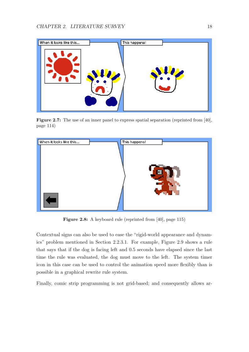
Figure 2.7: The use of an inner panel to express spatial separation (reprinted from [40],page 114)
Figure 2.8: A keyboard rule (reprinted from [40], page 115)
Contextual signs can also be used to ease the “rigid-world appearance and dynam-ics” problem mentioned in Section 2.2.3.1. For example, Figure 2.9 shows a rulethat says that if the dog is facing left and 0.5 seconds have elapsed since the lasttime the rule was evaluated, the dog must move to the left. The system timericon in this case can be used to control the animation speed more flexibly than ispossible in a graphical rewrite rule system.
Finally, comic strip programming is not grid-based; and consequently allows ar-

CHAPTER 2. LITERATURE SURVEY 19
Figure 2.9: A rule involving system clock (reprinted from [40], page 115)
bitrary placement of icons in the world. Icons can be resized, and are allowed tooverlap to any extent.
2.2.4 Programming by Demonstration
Programming by demonstration VPLs facilitate programming by using examples [49].By-demonstration VPLs are typically selection-action VPLs in the sense that anexample specifies a situation that the programming system should recognize; andan action that should be taken thereafter [17].
There are two approaches to programming by demonstration. The first approachis referred to as programming with examples in [49] and strict recording in [17].In this approach, the programming environment simply records user actions andthe context at program editing time; and replays the exact user actions when thecontext arises at runtime. The programming system does not attempt to discoverand generalise the underlying algorithm.
The second approach is referred to as programming by example in [49]. In this ap-proach, the programming system tries to infer a general algorithm from an exampleor a sample execution trace.
The by-demonstration approach is always used in combination with another rep-resentation approach, in which the examples are expressed. Macros in financial
CHAPTER 2. LITERATURE SURVEY 20
spreadsheet applications are an example of this approach.
Stagecast Creator[8] allows users to create graphical rewrite rules using the by-demonstration approach. The before and after pictures are created by using exam-ples of icons that are extracted from the runtime environment.
2.2.5 Building-block Programming
Building-block programming, also called jigsaw puzzle pieces programming in [49],uses tiles to compose a visual program. The tiles are designed such that they onlyfit together in ways that express legal expressions in the visual language.
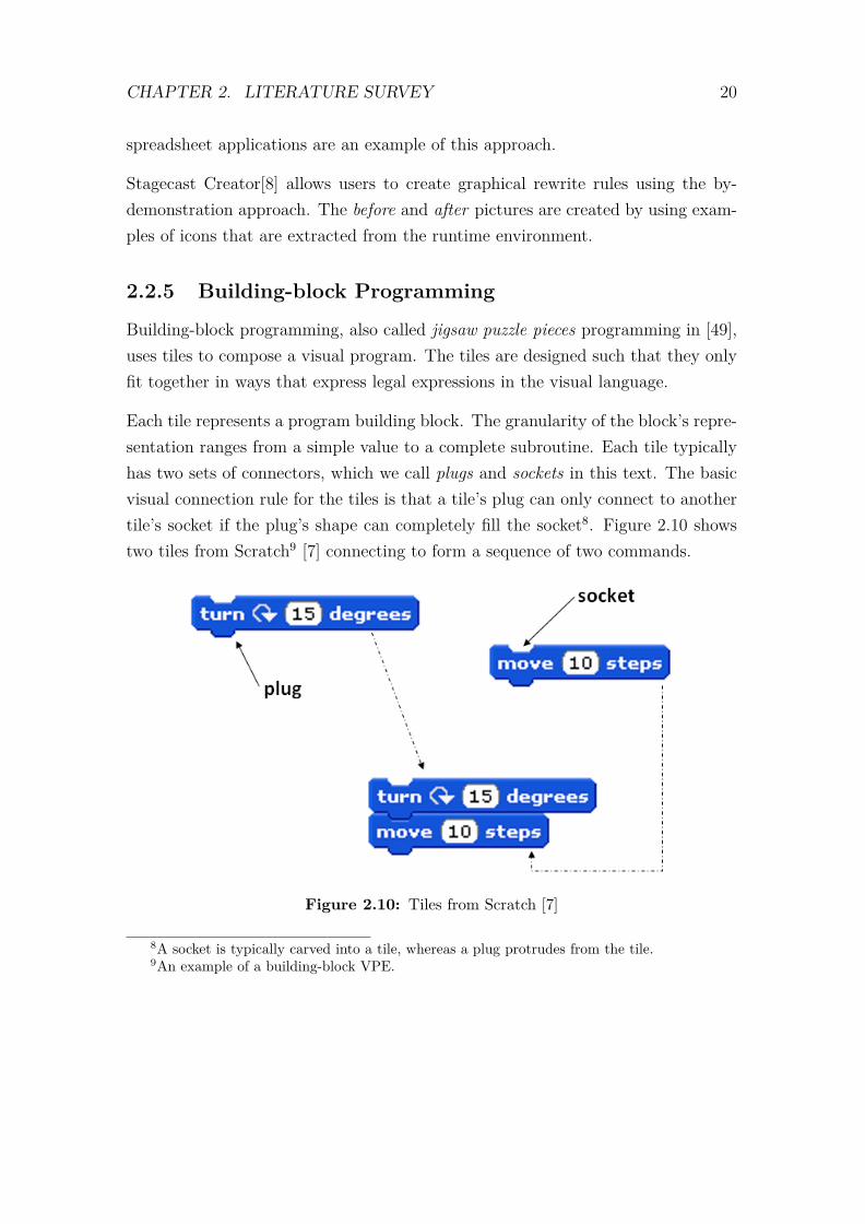
Each tile represents a program building block. The granularity of the block’s repre-sentation ranges from a simple value to a complete subroutine. Each tile typicallyhas two sets of connectors, which we call plugs and sockets in this text. The basicvisual connection rule for the tiles is that a tile’s plug can only connect to anothertile’s socket if the plug’s shape can completely fill the socket8. Figure 2.10 showstwo tiles from Scratch9 [7] connecting to form a sequence of two commands.
Figure 2.10: Tiles from Scratch [7]
8A socket is typically carved into a tile, whereas a plug protrudes from the tile.9An example of a building-block VPE.
CHAPTER 2. LITERATURE SURVEY 21
The building-block approach originated from the Glinert’s BLOX methodology [28,29], which is described by Kopache and Glinert in [43]. Some of the earliest systemsbased on this approach are C2 [43] and VITPE [58]. More recent building-blockprogramming systems are discussed in Section 2.3.
2.2.6 Discussion
This section discusses the factors that led to the adoption of the building-blockapproach for our VSE. We evaluate each of the representation technique describedin the preceding sections using the following criteria:
1. Fitness for purpose. The goal of the VSE system is to simplify the pro-gramming aspect of educational games development for our in-house gameengine. We assume the existence of prebuilt 3D models and static 3D scenes.The VPE that we seek must therefore support specification of the game logicwithout requiring the user to create 3D artefacts from scratch. There shouldalso be a loose coupling between the 3D artefacts and the VPE, so that newartefacts can be imported into the VPE without requiring reprogramming theVSE;
2. Effort required to develop a testable prototype. The time in which the the-sis was to be completed was limited; and as such, opportunities to cut theprototype development time were considered. One such opportunity was theavailability of an open source framework on which to base the VSE; and theother was the closeness of mapping between the representation technique andthe target textual programming language, so that less effort is expended ondeveloping the VSE’s code generator;
3. Expressiveness of the approach. Since the target audience of the VSE are notexpert programmers, we sought a representation technique that was simpleenough to learn; but, at the same time, expressive enough to express all thegame logic without having to use an additional representation technique.

CHAPTER 2. LITERATURE SURVEY 22
Form-based VPLs
The form-based VPL approach is limited to the declarative programming paradigm.However, the specification of 3D game logic entails controlling the order of executingvarious animations, among other things. This entails that a language to support thespecification of game logic should support the expression of sequences. Although itmay be argued that order of events can be expressed in a declarative language, thisusually requires a greater cognitive effort than would be the case if an imperativelanguage was used [27].
Another difficulty with using the form-based approach is extensibility. Form-basedVPLs, such as Forms/3 [21], that include graphics as first class types, use otherforms to define user-editable attributes of the graphical types. We concluded thatit would not be feasible in our case to use the form-based paradigm to expressthe low level instructions necessary to render the “graphical values.” This idea isexemplified in Forms/3, where the low-level instructions for drawing the graphicsare contained in hidden cells that are not user-editable. The low level instructions,however, can refer to the user-editable attributes controlling the size of the image,for example.
If the form-based VPE is to be extensible through the addition of third-partygraphical types, then there would be a need for a simple mechanism for linking user-editable attributes of the graphical types to the low level instructions responsiblefor rendering the graphics. Forms/3, for example, supports user-defined graphi-cal types in a restricted way. First, the user-defined graphical type can only becomposed from the built-in graphical types; and, secondly, composition is specifiedtextually in a cell. The textual input in this case is non-trivial since it embedsthe logic of rendering the graphics. This detracts from the intention of loweringbarriers to programming.
Furthermore, we intend to use pre-existing 3D models; and we do not want toburden the user with understanding the composition of the models. The usercannot create forms to fully represent the 3D models’ attributes and behaviourswithout this knowledge.
The target textual programming language for the VSE’s code generator is imper-ative whereas form-based VPLs are inherently declarative. This implies a wide

CHAPTER 2. LITERATURE SURVEY 23
gap between the textual representation of the visual program and the target pro-gramming language; and thus a lot of effort would be required to develop the codegenerator in our situation.
Dataflow VPLs
Dataflow languages offer an improvement over the lack of explicit expression ofsequence observed in form-based languages. The order of firing of nodes on aspecific path is predictable; although the order is indeterminate for two nodesappearing on different paths. The dataflow model is inherently a parallel executionmodel [38]; and therefore simplifies the specification of parallel threads.
The dataflow approach has limited scalability. As the number on nodes and edgesincreases, the logic becomes increasingly difficult to follow. Furthermore, there isnot much room on the screen to render the dataflow graph such that no edges cross.The criss-crossing edges detract from readability of the program.
The parallel nature of the dataflow execution model presents a challenge whentranslating the visual program into the target textual language. This problemderives from the lack of constraints on the order of firing of nodes appearing onparallel paths. A single dataflow visual program has the potential to map intoseveral sequential programs with different semantics. A substantial amount ofeffort would therefore be required to develop a code generator for such a visualprogramming language.
Iconic VPLs
Iconic VPLs normally use direct manipulation when creating the before and af-ter pictures. For instance, icons can be dragged around in order to change theirpositions in the runtime environment. The VSE’s runtime environment is a 3Dvirtual world as opposed to the 2D world in iconic VPEs like Stagecast Creatorand ComiKit [40]; and as such, the use of direct manipulation to create the rulesbecomes less intuitive when manipulating a 3D scene that is displayed on a 2Dscreen.
The 3D environment introduces additional degrees of freedom with respect to objectplacement; and this increases the difficulty that iconic languages have in generaliz-

CHAPTER 2. LITERATURE SURVEY 24
ing situations. For example, whereas eight graphical rewrite rules are required in a2D grid-based world to state that when a dog is sitting next to a ghost, the ghostdisappears; twenty six rules would be required in a 3D grid-based world to expressthe same rule.
Creating games goes beyond making characters react to various situations. Someinformation, which cannot have a visual representation in the runtime environment,needs to be maintained in a game. The execution model of rule-based iconic VPLsis that when a situation in the runtime environment matches the before picture ofa rule, then the action implied from the after picture is executed. Since a variable,such as one used to track the player’s score, does not have a visual presence; arule involving the variable cannot be formulated or executed. This weakness isdemonstrated in Stagecast Creator, where the graphical rewrite rules are augmentedwith a form-based approach in order to support variables and user interaction.
Rule-based iconic VPLs are declarative; and thus suffer from the same sequencingproblem discussed above under form-based and dataflow VPLs.
By-demonstration VPLs
Programming by demonstration is not a stand-alone paradigm. It relies on otherrepresentation techniques to represent the example; thus the limitations of theunderlying representation technique are inherited. Moreover, each of the two ap-proaches to programming by demonstration has its own weakness.
The strict recording approach suffers from a lack of generalisation. The exactsequence of recorded actions is repeated when a runtime context that resembles aprogram editing time context arises.
The programming by example approach suffers from another form of the gener-alization problem. The problem stems from the attempt to guess the algorithmunderlying the examples demonstrated by the user. Landauer and Hirakawa [44]suggest that users may provide insufficient examples, missing out important specialcases; and consequently the system may guess an invalid generalisation.

CHAPTER 2. LITERATURE SURVEY 25
Building-block VPLs
The building-block approach can be considered a visualization of an underlyingtextual language. This means that a building-block VPL can be given as muchexpressive power as a textual language without requiring the use of an additionalrepresentation technique. This is advantageous to the users since they only needto learn one program expression technique. At the same time, the use of thebuilding-block technique eliminates the need for the user to worry about the syn-tactic correctness of the program. Syntactic correctness is enforced automaticallyby taking the burden of typing syntactic tokens from the user; and allowing onlysyntactically correct composition of building blocks representing tokens.
The other attractive aspect of the building-block approach is that the closenessof mapping between the VPL and the target textual programming language canbe increased intentionally. This affords us the opportunity to reduce the amountof effort required to develop the VPL-to-textual-programming-language translator.We were also able to find open source frameworks that support rapid developmentof building-block VPLs.
Despite the advantages discussed above, building-block VPLs, like all VPLs, stillsuffer from the Deutsch limit [9], which states that the size of problems that canbe solved by a visual program is limited since no more than fifty graphical pro-gramming icons can be legibly displayed on the screen. The extent to which thislimitation is addressed is discussed in Chapter 3.
In the following section, we look at three examples of game authoring tools thatuse the building-block visual program representation technique.
2.3 Related Visual Game Generators
This section discusses three examples of game authoring VPEs based on the building-block representation techniques. The VPEs are Scratch, Alice and StarLogo TNG.The VPEs were chosen because they are open source; and therefore presented an op-portunity to reuse their visual expression subsystems. Other building-block-basedVPEs include LogoBlocks [19], Pet Park Blocks [26] and App Inventor [3].
CHAPTER 2. LITERATURE SURVEY 26
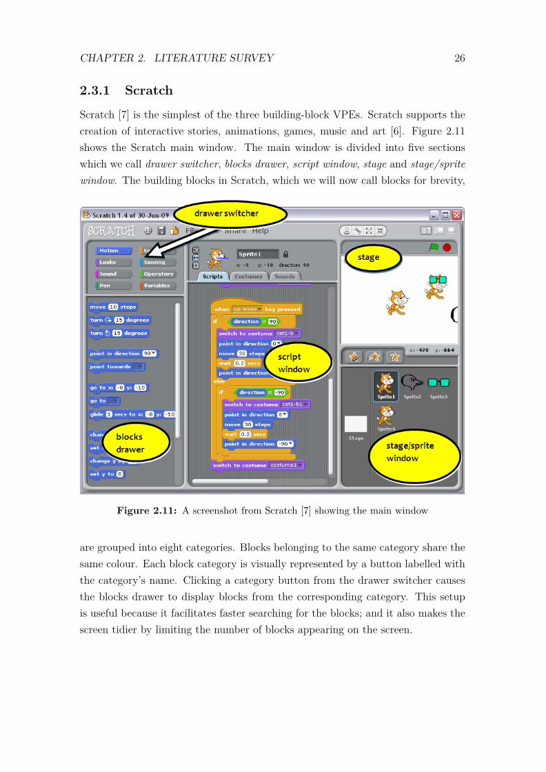
2.3.1 Scratch
Scratch [7] is the simplest of the three building-block VPEs. Scratch supports thecreation of interactive stories, animations, games, music and art [6]. Figure 2.11shows the Scratch main window. The main window is divided into five sectionswhich we call drawer switcher, blocks drawer, script window, stage and stage/spritewindow. The building blocks in Scratch, which we will now call blocks for brevity,
Figure 2.11: A screenshot from Scratch [7] showing the main window
are grouped into eight categories. Blocks belonging to the same category share thesame colour. Each block category is visually represented by a button labelled withthe category’s name. Clicking a category button from the drawer switcher causesthe blocks drawer to display blocks from the corresponding category. This setupis useful because it facilitates faster searching for the blocks; and it also makes thescreen tidier by limiting the number of blocks appearing on the screen.

CHAPTER 2. LITERATURE SURVEY 27
The blocks drawer contains instances of blocks that can be used to build programs.Each block instance in the blocks drawer is capable of generating an infinite numberof replicas of itself, in theory. When a user drags a block from the blocks drawer,the block is duplicated; and the original block remains in the blocks drawer whereasthe new copy can be dropped into the script window. When a block is dragged anddropped back into the blocks drawer, it is deleted.
The script window is where the script is crafted. Scratch maintains as many scriptwindows as the numbers of sprites on the stage; however, only one script windowis displayed at a time. A script window for a particular sprite can be displayed byselecting the corresponding sprite from the stage/sprite window.
Scratch supports event-driven programming through the four when blocks shownin Figure 2.12. A stack of blocks, whose top block is connected to a when block, isexecuted when the event stated in the when block occurs at runtime.
Figure 2.12: Scratch’s event blocks
These four when blocks also facilitate the specification of concurrent scripts. Fig-ure 2.13 shows an example of using when blocks to express concurrency. Sincethe play note and the play drum blocks are attached to separate instances ofthe when...key pressed block (each instance having the same parameter, namely,space), the play note and play drum blocks are executed concurrently when theuser presses a space keyboard key at runtime.
Figure 2.13: Concurrency in Scratch

CHAPTER 2. LITERATURE SURVEY 28
Scratch also supports the definition and manipulation of variables and lists. Bothvariables and lists can be defined as global, in which case they are available in allscript windows for the project. Variables and lists can also be defined as local, inwhich case they are only available in the script window for the sprite for which theyare defined.
We observed the following weaknesses in the Scratch VPE:
1. Lack of support for modularity. Scratch does not implement any mechanismto fully support modular abstraction. There is, however, limited modularitywhich results from the isolation of scripts when the script uses more than oneevent block (when... block). This limited modularity cannot be used to im-plement abstraction. The lack of abstraction means the script for controllinganimation is tightly coupled with the script controlling the high level logic ofthe games; thus the user is forced to reason about animation and game logicsimultaneously;
2. Lack of a visual representation of constants. Scratch does not have a setof blocks representing various types of constants10. This means that con-stant values have to be typed directly into the expressions in which they arerequired. Although blocks representing algebraic operators screen out non-numeric data, syntax errors11 are still possible as demonstrated in Figure 2.14.In the figure, the add...to... block inserts the string, “scratch”, into the emptylist, list2. The item...of... block returns the first item of list2. The “mul-tiply” block multiplies 2 and the string “scratch”12. The say... block displaysthe result of the multiplication in a sprite’s callout. Figure 2.15 shows theresult of running the script;
3. Misleading implementation of lists. The add...to... block accepts variablesrepresenting lists in the first socket, meaning that a list can be inserted intoanother list. There is, however, no expression for extracting elements of anested list;
10Scratch has only one block representing the two types of supported variables, namely numericand text.
11Scratch conveniently treats syntax errors as runtime errors, affecting only the computedresult.
12This connection should have been rejected.

CHAPTER 2. LITERATURE SURVEY 29
Figure 2.14: A syntax error in Scratch: an attempt to multiply a number and a string
Figure 2.15: The syntax error in Figure 2.14 treated as a runtime error by Scratch
4. Representation technique shifts. Scratch lacks blocks for defining variablesand lists. Variables and lists are defined by using forms, which is a deviationfrom the building-block representation technique.
2.3.2 Alice
Alice [2] is a VPE that simplifies creation of 3D virtual environments. Alice canbe used to create interactive stories, games and videos. At the time of writing thisthesis, the latest release version was Alice 2.2; however, there was also an Alice3.0 beta version. There are no significant changes between Alice 2.0 and Alice 2.2;and as such, our analysis is based primarily on version 2.0. In Alice 3.0, the visualprogram representation is almost the same as that in Alice 2.0. The major changethat we noted, concerns the screen layout.
The Alice 2.0 main window, shown in Figure 2.16, is divided into five sections,namely:

CHAPTER 2. LITERATURE SURVEY 30
Figure 2.16: A screenshot from Alice [2] showing the main window
1. World window. This window offers a preview of a 3D scene that is beingcreated. The window allows a user to specify the initial placement of objectsin the scene, in a direct manipulation manner. The objects can be movedaround, resized and rotated by using the mouse and keyboard.
2. Object tree window. This window displays all the programmable objects ap-pearing in the world window. In Alice 2.0, objects are hierarchical; for ex-ample, a “man” object has a hand which in turn has a finger. Animationscan be specified on the whole object; or on its individual parts. The objectwindow thus facilitates selection of objects and their parts;

CHAPTER 2. LITERATURE SURVEY 31
3. Details area. This area displays all the properties, methods and functionsdefined on an object selected from the object tree window.
4. Editor area. This is where scripts are composed. Below the editor area, thereis a panel containing control flow blocks.
5. Events area. Alice supports event-driven programming; and this area is usedfor connecting events with their events handlers.
The blocks in the details area, and in the panel below the editor area, generatean infinite number of instances of program building blocks, like the blocks in ablocks drawer in Scratch; but, unlike in Scratch, these blocks have the same shape.In Alice, the blocks only take on their final differentiated shapes when they aredropped in either the editor area or the events window. The blocks in the de-tails area, and in the panel below the editor area, can thus be considered iconsrepresenting the final program building blocks.
Concurrent programming is supported in Alice through the use of do together andfor all do together blocks. The do together block is a container that holds methodsand functions that must be executed in parallel. The for all do together is also acontainer block that is used to repeatedly execute several functions and methodsin parallel.
Alice also supports the declaration and manipulation of variables and lists. UnlikeScratch, Alice is a strongly typed VPE. All user-defined variables and lists/arrayshave a global scope in Alice.
The Alice VPE has the following shortfalls:
1. Similarity of blocks. All the program building blocks in Alice have a similarouter outline, the box outline. The logical structure is thus not easy to spotat a glance. The problem is worsened by the subtle difference in colour amongthe different types of blocks and the background. Consequently, the appear-ance of scripts is more textual than graphical. This problem is illustrated inFigure 2.17.

CHAPTER 2. LITERATURE SURVEY 32
Figure 2.17: Alice blocks’ lack of differentiated shape outlines
2. The absence of a connector metaphor. Connections among the blocks in aprogram are not explicit. There are no traditional matching sockets and plugsto visually suggest compatibility of blocks. This problem has been partiallyaddressed in Alice 3 beta – all functional blocks have compatibility suggestiveconnectors; however the problem still remains in command and flow controlblocks.
3. Representation technique shifts. The problem of representation techniquechanges when handling advanced concepts is not limited to variable/list def-initions as in Scratch. A combination of forms and menus is also used whenentering constant values, and when building algebraic, relational and logicalexpressions.
4. Breakdown of abstraction in Alice 3.0 beta. We observed a mismatch of objectabstraction between object references in the object selector and the editorarea. For instance, a cat’s head can be selected by first selecting the cat,and then its head from two drop-down lists; but, in the editor area, the cat’shead is represented by a function call which returns a head, whose argumentis another function call which returns a cat. This functional representationcan be confusing since it represents a shift from a higher level of concretenessto a lower level.
5. Fine grain animation. The hierarchical structure of objects in Alice affordsthe users the possibility of fine grain animations, such as moving an armrelative to the torso of a person. The correct specification of such animations

CHAPTER 2. LITERATURE SURVEY 33
requires significant skill in 3D geometry to prevent, say, the arm disconnectingfrom the torso.
6. Strict insistence on connectedness. Alice does not permit the placing of ablock in the editor area if it does not form part of the script in the editorarea. This is inconvenient since, for example, a complex algebraic expressioncannot be rearranged without first deleting some components and redraw-ing them from the details area. In an ideal situation, the system shouldhave allowed the components to be temporarily unconnected to facilitate re-structuring of the algebraic, relational and logical expression without thedelete-redraw sequence.
7. Inefficient use of the screen real estate. Although Alice supports modularabstraction through functions and methods, all the user-defined methods andfunctions are displayed in the script area at all times. Alice 3 beta exacer-bates the problem by eliminating the events area, which means that all eventhandlers have to be defined and linked in the editor area.
2.3.3 StarLogo TNG
StarLogo TNG13 was designed for the creation of simulations of complex systems [4].It uses blocks similar to those used in Scratch; but unlike Scratch, StarLogo TNG’sruntime environment is a 3D virtual world.
StarLogo TNG’s VPL addresses all the problems we identified in Scratch and Alice.We defer the detailed description of the VPE in StarLogo TNG to Chapter 3 toavoid repetition since the design of our VSE is largely based on StarLogo’s front-endsubsystem.
2.4 Chapter Summary
This chapter began by providing an informal definition of visual programming. Itintroduces the two concepts of a visual programming language (VPL) and a visualprogramming environment (VPE); and states the difference, which is based on
13TNG stands for The Next Generation.

CHAPTER 2. LITERATURE SURVEY 34
the presence or absence of an underlying textual programming language. It alsodescribes goals of visual programming; and the four approaches to achieving thegoals, namely: concreteness, directness, explicitness and immediate visual feedback.
The chapter then discusses five visual program representation techniques, namely:form-based, dataflow, iconic, by-demonstration and building-block. We argued thatthe building-block approach is the most suitable for our problem because of its highdegree of expressiveness; its abstraction of low-level syntax; its closeness of mappingto the target textual programming language; and the availability of an open sourceframework on which to build our prototype.
The chapter ends with a discussion on three open-source examples of VPEs that usethe building-block representation technique. We compare the three VPEs with theaim of identifying the best framework on which to base our prototype. StarLogoTNG’s VPE was identified as the most suitable for our purposes.
In the next chapter we discuss the design of our VSE.

Chapter 3
The VSE ProgrammingEnvironment
This chapter discusses the design of a prototype visual programming environmentfor creating scripts to run on the Myoushu game engine. The prototype is calledthe visual script editor (VSE). We discuss how the VSE prototype is realized byextending the OpenBlocks system. One such extension is the inclusion of extraconnector shapes that can be used to create additional data types.
We also discuss the design of additional modules that further simplify the creationof games that run on the Myoushu game engine. Examples of such additionalmodules include: a scene object manager, which inspects XML scene files andcreates blocks representing scene objects; and a game GUI manager, which scansGUI layout files and creates blocks representing GUI widgets.
Section 3.4.5 discusses the code generator module. Despite the syntax error avoid-ance property of the building-block visual program representation technique, compile-time errors and warnings can still occur. We discuss the source of these errors andwarnings; and the measures taken to tackle the errors and warnings, in the codegenerator module.
OpenBlocks-based visual programs are stored in text files, in XML format. TheseXML files are quite large compared to the corresponding Lua script files generatedfrom the visual programs, and the file size ratio typically exceeds 10:1. Whenreading in the visual programs from the XML files, the XML content is first parsed
35

CHAPTER 3. THE VSE PROGRAMMING ENVIRONMENT 36
into DOM [5] trees; and then the DOM trees are processed to generate directedgraphs, which are OpenBlocks’ (and consequently VSE’s) internal representationof visual programs. These graphs are memory intensive. In Section 3.4.6 we discussmeasures that we have taken to reduce this memory footprint.
We begin this chapter by providing an overview of the game production process,in the context of the Myoushu game engine.
3.1 The Game Production Process
The process of creating a 3D game involves several activities, including: the designof a storyline; the design and development of 3D game objects, or the acquisitionof prebuilt 3D game objects; building scenes using the 3D game objects; creatinganimations for some of the 3D game objects; specifying when to execute the variousanimations; and specifying mechanisms to keep track of the state of the game.
As mentioned in Chapter 1, our work does not include the development of storylines.We assume the existence of a storyline for which a 3D virtual world is sought. Wealso assume the existence of prebuilt 3D game objects and scenes. We briefly discuss3D game objects and scenes because they are part of the direct input to the gameengine; and they also are a source of information that is critical to the operationsof the VSE.
3.1.1 The Game Engine
The design of our VSE is constrained by the Myoushu game engine, which wasdeveloped by Chamberlain [61]. Henceforth, we use the phrase “the game engine”to refer to the phrase “the Myoushu game engine”. The game engine’s majorinputs include: Lua script files; 3D scene definition files; 3D game object definitionfiles; graphical user interface (GUI) layout definition files; sound files, educationalcontent files; and user input through the mouse and keyboard.
The Lua scripts specify the game logic which manipulates 3D scenes; controls anyGUI that appear in the virtual environment; keeps track of the state of the game;keeps track of the player’s performance measure; and handles user input.
CHAPTER 3. THE VSE PROGRAMMING ENVIRONMENT 37
Before we discuss the challenges posed by the Lua scripting interface to both ex-perienced and inexperienced programmers, we describe the relationships betweenthe game engine and 3D scenes; and between the game engine and the virtualenvironments’ GUIs.
3.1.2 3D Models and Scenes
3D scenes are passed to the game engine through text files, in XML format, calledDotscene files. Dotscene files contain only the scene layout and animations definedfor the 3D objects in the scene. The layout information includes the 3D coordinatesat which an object is placed, and the orientation of the object. The actual 3D gameobject geometry definitions are stored in separate files, called mesh files.
When the game engine renders a scene in a 3D virtual environment, it begins byreading the contents of a Dotscene file; and then locating all the mesh files namedin the Dotscene files. The game engine then renders each game object in the scene;and uses shading and texture details specified in a materials file to colour andtexture the game objects.
Once a scene has been rendered, animations defined for some of the 3D game objectscan be executed. Instructions to load a scene and execute a particular animationdefined in the scene can be specified in a Lua script.
3.1.3 Graphical User Interface
GUI definitions are stored in text files, called GUI layout files. GUI layout filesare in XML format. The layout file defines the various widgets appearing on aparticular GUI. This file specifies the 2D coordinates of each widget, the widgets’names and other attributes that control the appearance of the widgets. The filealso associates a widget’s event name with the name of an event handler for eachwidget whose events must be handled.
When the game engine receives a request to display a particular GUI, it reads theGUI layout file and creates all the widgets described in the file. Each widget’sname becomes available to the Lua script controlling the GUI. The widgets canthus be manipulated by passing their names to special Lua library functions. A
CHAPTER 3. THE VSE PROGRAMMING ENVIRONMENT 38
Lua script controlling a GUI needs to provide the definition of an event handler foreach widget’s event that was associated with an event handler name in the GUIlayout file. The name of the event handler in the Lua script must match the nameof the event handler name in the GUI layout file.
3.1.4 The Lua Scripting Challenges
The game engine has a Lua scripting interface. Lua scripts are used to specifygame logic which manipulates scenes and GUIs. The Lua scripting interface poseschallenges to the specification of game logic to both experienced and inexperiencedprogrammers.
Before the advent of the VSE, there was no integrated development environment(IDE), be it textual or visual, to simplify the management of the enormous amountof information that must be available when creating the Lua scripts. The authorof a Lua script needs to be aware of the programmable content of a scene or anin-game GUI. Although this information is contained in the Dotscene and the GUIlayout XML files, it is rather inconvenient for a programmer, whether experiencedor inexperienced, to be manually searching these files for programmable elements.Consequently, there is need for an IDE capable of browsing the XML files andextracting script related information; and displaying such information to the user.
Lua is a textual programming language whose mastery requires a significant amountof effort to be expended in learning the syntax. If the person learning Lua isabsolutely new to programming, he/she must also learn computational thinking inaddition to learning the syntax. Computational thinking skills are indispensablein game logic specification; however, the syntax burden adds no value to the gamecreation process, and hence our desire to eliminate it.
The target audience of our VSE is ASDs therapy specialists. These are domainexperts, but are not necessarily programmers. We seek to empower the therapistswith a tool to enable them to rapidly create therapeutic games to match theirpatients’ diverse specific needs. We do not, however, want to force them to learnthe syntax of Lua.
The next section discusses the design objectives of the VSE.
CHAPTER 3. THE VSE PROGRAMMING ENVIRONMENT 39
3.2 Design Objectives
To lower the barriers to scripting discussed in Section 3.1.4, we considered devel-oping an IDE, the VSE, with the following objectives:
1. to represent the majority of scripting commands and expressions by graphicalelements, so that scripting can be done using a predominantly drag-and-dropinteraction style;
2. to represent programmable scene and GUI artefacts by graphical elementsthat are compatible with the graphical elements in 1;
3. to present the user with a simple-to-use interface for managing scenes andtheir content;
4. to present the user with a simple-to-use interface for managing GUIs andtheir content;
5. to automate the process of exporting scripts and other resources to the gameengine for execution; and
6. to generate Lua scripts from the graphical programs mentioned in 1. TheLua code should be human-readable to the extent that it can be modified bya skilled Lua programmer.
Objectives 1 and 2 allow the virtual environment (VE) author to specify the VElogic without the need to learn the syntax of Lua, the target language. The au-thor will, however, still need to master the art of computational thinking1; which,coincidentally, is a by-product of using our VSE due to the nature of the visualprogramming representation technique that we have adopted [33].
Objectives 3 and 4 allow the author to discover the abstract contents of scene filesand GUI layout files without having to manually inspect the XML files representingscenes and GUIs. This is necessary since the Dotscene files are quite large, evenfor modest scenes.
1Wing [62] describes computational thinking as “solving problems, designing systems andunderstanding human behaviour, by drawing on the concepts fundamental to computer science”
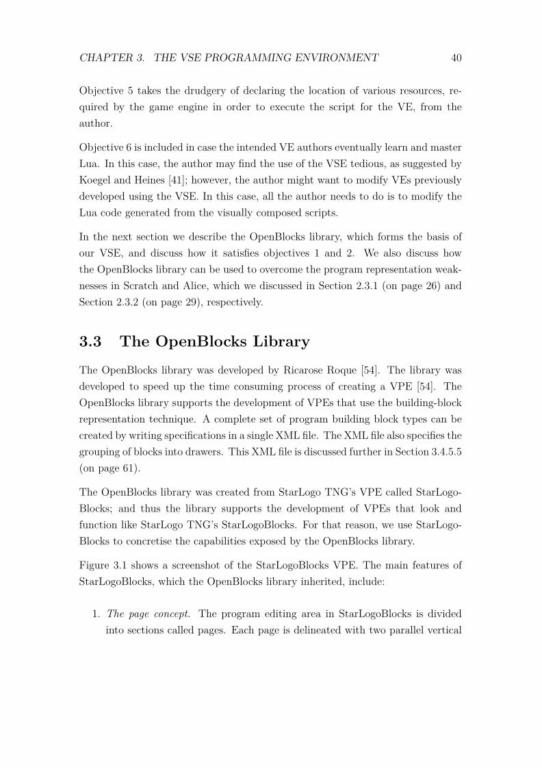
CHAPTER 3. THE VSE PROGRAMMING ENVIRONMENT 40
Objective 5 takes the drudgery of declaring the location of various resources, re-quired by the game engine in order to execute the script for the VE, from theauthor.
Objective 6 is included in case the intended VE authors eventually learn and masterLua. In this case, the author may find the use of the VSE tedious, as suggested byKoegel and Heines [41]; however, the author might want to modify VEs previouslydeveloped using the VSE. In this case, all the author needs to do is to modify theLua code generated from the visually composed scripts.
In the next section we describe the OpenBlocks library, which forms the basis ofour VSE, and discuss how it satisfies objectives 1 and 2. We also discuss howthe OpenBlocks library can be used to overcome the program representation weak-nesses in Scratch and Alice, which we discussed in Section 2.3.1 (on page 26) andSection 2.3.2 (on page 29), respectively.
3.3 The OpenBlocks Library
The OpenBlocks library was developed by Ricarose Roque [54]. The library wasdeveloped to speed up the time consuming process of creating a VPE [54]. TheOpenBlocks library supports the development of VPEs that use the building-blockrepresentation technique. A complete set of program building block types can becreated by writing specifications in a single XML file. The XML file also specifies thegrouping of blocks into drawers. This XML file is discussed further in Section 3.4.5.5(on page 61).
The OpenBlocks library was created from StarLogo TNG’s VPE called StarLogo-Blocks; and thus the library supports the development of VPEs that look andfunction like StarLogo TNG’s StarLogoBlocks. For that reason, we use StarLogo-Blocks to concretise the capabilities exposed by the OpenBlocks library.
Figure 3.1 shows a screenshot of the StarLogoBlocks VPE. The main features ofStarLogoBlocks, which the OpenBlocks library inherited, include:
1. The page concept. The program editing area in StarLogoBlocks is dividedinto sections called pages. Each page is delineated with two parallel vertical
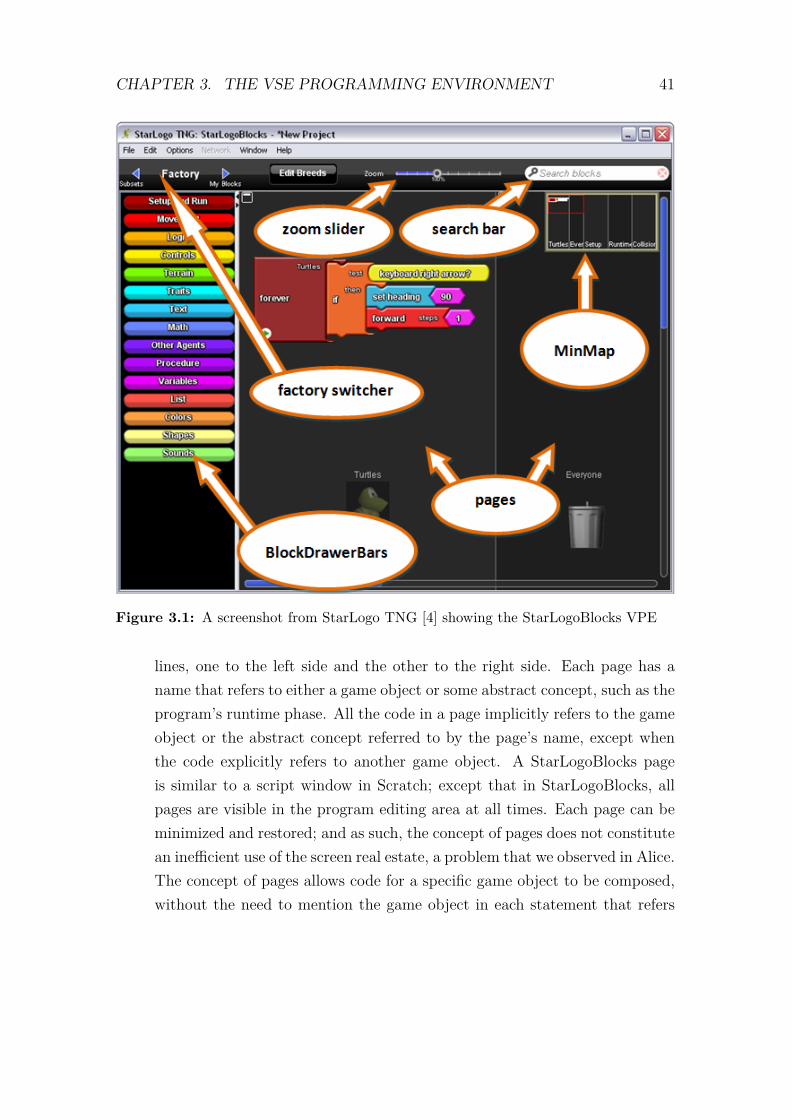
CHAPTER 3. THE VSE PROGRAMMING ENVIRONMENT 41
Figure 3.1: A screenshot from StarLogo TNG [4] showing the StarLogoBlocks VPE
lines, one to the left side and the other to the right side. Each page has aname that refers to either a game object or some abstract concept, such as theprogram’s runtime phase. All the code in a page implicitly refers to the gameobject or the abstract concept referred to by the page’s name, except whenthe code explicitly refers to another game object. A StarLogoBlocks pageis similar to a script window in Scratch; except that in StarLogoBlocks, allpages are visible in the program editing area at all times. Each page can beminimized and restored; and as such, the concept of pages does not constitutean inefficient use of the screen real estate, a problem that we observed in Alice.The concept of pages allows code for a specific game object to be composed,without the need to mention the game object in each statement that refers

CHAPTER 3. THE VSE PROGRAMMING ENVIRONMENT 42
to the game object;
2. The MinMap. The MinMap is a miniature representation of the entire pro-gram editing area. It facilitates rapid navigation within the program editingarea. A user can navigate to a remote section of the program by selecting thesection from the MinMap;
3. The factory switcher. StarLogoBlocks supports two types of block drawers2,namely static and dynamic drawers. Static drawers are fixed and cannot bechanged by user action in a typical programming session. On the other hand,dynamic drawers are not fixed during a typical programming session. Dy-namic drawers are automatically added and deleted as breeds3 are added andremoved from a program. Dynamic drawers hold, among others, blocks formanipulating user-defined variables, procedures, functions and actual param-eters. The factory switcher is used for switching between static and dynamicdrawer sets;
4. BlockDrawerBar. A BlockDrawerBar is used for opening a drawer. Unlikein Scratch, block drawers in StarLogoBlocks remain closed until a user opensa drawer to use its contents. Once a block has been dragged out of a blockdrawer, the drawer returns to its closed state. This arrangement allows Star-LogoBlocks to handle more block categories without cluttering the screen;
5. The zoom slider. The zoom slider controls the level of magnification of theprogram editing area, thus controlling the number of blocks viewable perscreen area. This feature accommodates users with diverse visual acuities;
6. The search bar. The search bar facilitates searching for program buildingblocks. This feature becomes handy when a user knows the name of theblock he/she seeks to drag out of a drawer, but has forgotten the name ofthe drawer holding the block. The user is not required to type the completename of the block since StarLogoBlocks searches for all blocks whose labelscontain the text entered by the user.
2Containers holding instances of program building blocks.3A breed in StarLogo TNG refers to a collection of scene objects of the same kind. Each breed
is assigned a page on which to specify logic which controls every member of the breed.

CHAPTER 3. THE VSE PROGRAMMING ENVIRONMENT 43
StarLogoBlocks uses blocks similar to Scratch’s blocks. These blocks do not sufferfrom the lack of differentiated outer shape and the lack of a connector metaphor,a problem that we observed in Alice. The StarLogoBlocks library has a constraintthat all programming entities, including constants, be represented by blocks. Thisconstraint eliminates syntax errors stemming from the lack of blocks representingconstant values, which were observed in Scratch.
The lack of modular abstraction in Scratch is addressed by StarLogoBlocks in twoways. First, StarLogoBlocks has a block for defining procedures and functions.Once a procedure or a function has been defined, StarLogoBlocks automaticallycreates blocks that can be used to call the procedure/function. Secondly, the con-cept of pages in StarLogoBlocks implements a modular abstraction similar to thatof a class in an object oriented programming language, but in a limited way. Onlyprocedures/functions, defined on one page, are available to other pages. Any codethat is outside a procedure/function is not available in the other pages, except forglobal variables.
The problem of representation technique shifts, in both Scratch and Alice, whendefining variables and lists is nonexistent in StarLogoBlocks. StarLogoBlocks hasblocks for defining variables and lists. Once a variable or a list has been defined,StarLogoBlocks automatically provides blocks for manipulating the variable/list.No forms4 are used when defining variables.
The breakdown of abstraction observed in Alice 3.0 beta is absent in StarLogo-Blocks. The problem in Alice arises due to the use of icons to represent blocktypes, and only allowing the block instances to take their final form when they aredropped into the editor area. On the other hand, blocks in StarLogoBlocks arenever iconified when they are in the block drawer; and therefore a block’s appear-ance is the same regardless of its location.
StarLogoBlocks does not support breaking down a game object into its parts; andthus the problems stemming from attempts to write code to implement fine grainanimations do not arise. The task of implementing fine grain animations is left tothe author of the 3D model and not the user of the VPE.
4Forms, as a visual program representation technique, as discussed in Section 2.2.1 (on page 9).

CHAPTER 3. THE VSE PROGRAMMING ENVIRONMENT 44
Unlike Alice, StarLogoBlocks does not insist on strict connectedness of blocks ap-pearing in the program editing area. This means that programs can be reorganisedin a more flexible manner.
StarLogoBlocks affords the opportunity to manage the screen real estate, unlikeAlice. The screen can be managed in three ways:
1. by minimizing and restoring pages;
2. by using the zoom slider to control the number of blocks visible per unit area;and
3. by collapsing and expanding procedure/function definition code. Figure 3.2shows an example using this feature. Part (a) shows an expanded version ofa procedure definition stack. Part (b) shows the same procedure definitionstack with its body collapsed.
Figure 3.2: Screenshots from StarLogo TNG showing code folding
Lane et al [45] report that graphical user interfaces comprising menus, icons andtoolbars detract from the potential productivity of experienced users. Lane etal [45] motivate the provision of keyboard shortcuts to enhance the productivityof experienced users. McCaffrey [46] extended the StarLogoBlocks by adding afeature called TypeBlocking, which allows blocks to be drawn on a page using onlythe keyboard.

CHAPTER 3. THE VSE PROGRAMMING ENVIRONMENT 45
TypeBlocking does not break the building-block representation technique; rather,it is a keyboard shortcut for a sequence of actions that includes: selecting theappropriate BlockDrawerBar panel; clicking the desired BlockDrawerBar; scrollingto the desired block; and dragging and dropping the block onto a page. Thissequence of actions can be replaced by typing the first few letter of a block labeland pressing “enter” when a unique match is found.
3.4 The Design of the VSE
Figure 3.3 shows the major modules of our VSE system. The arrows in the figurepoint from the client side of the relationship between two modules. The scene object
Figure 3.3: The VSE system overview
manager is responsible for informing the OpenBlocks module of blocks representingscene artefacts that the OpenBlocks module needs to create and put in appropriateblock drawers. The collision blocks manager keeps tracks of information on possiblecollisions among game objects and informs the OpenBlocks module of the collision

CHAPTER 3. THE VSE PROGRAMMING ENVIRONMENT 46
handler blocks that are required in the collisions drawer. The game GUI managermaintains information about game GUIs that need to be programmed, and informsthe OpenBlocks module about the required blocks representing GUIs and widgets.The blocks verifier is used by the code generator module to check for potentialcompile-time errors and warnings. The code generator generates Lua code from avisual program in the OpenBlocks module. The game configuration manager setsup a complete game configuration that can be exported to the game engine forexecution.
These modules are discussed further in Sections 3.4.1 through 3.4.5.
3.4.1 Extensions to the OpenBlocks Library
3.4.1.1 Connector Shapes
The latest version of the OpenBlocks library, at the time of writing this thesis,had only fourteen connector shapes. This meant that for a non-trivial VPE suchas StarLogoBlocks, the connector shapes had to be reused in several dissimilarcontexts.
Roque [54] discusses a problem, emanating from overloaded block connector shapes,that was exposed through user tests. Block connector shape overloading refers tothe use of one block connector shape to represent more than one block connectionrule. An example of an overloaded connector shape in StarLogoBlocks is the com-mand connector shape. Algorithm 3.1 shows the command connector shape’s com-pound connection rule, which embeds two basic connection rules in an if-then-elsestructure. In the algorithm, the two blocks that are being considered for connectionare block1 and block2; and one of the blocks has the socket, socket, while theother block has the plug, plug.
Figure 3.4 shows an example, from StarLogo TNG, of the breakdown of the plug-socket connector metaphor due an overloaded command connector shape. In parts(a) and (b) connection is rejected, even though the socket and plug shapes seemcompatible, because exactly one of the blocks is a setup block. In part (c) theconnection is accepted since both blocks are setup blocks; and in part (d) the con-nection is accepted since neither of the blocks is a setup block. This is a departure
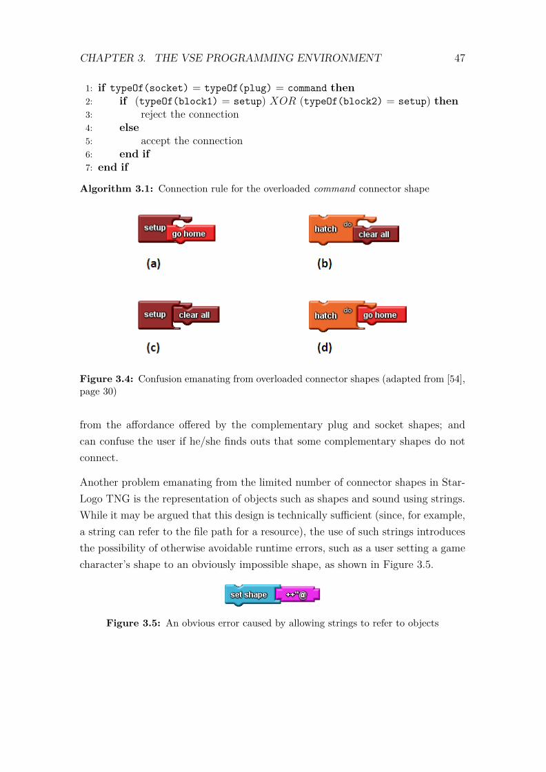
CHAPTER 3. THE VSE PROGRAMMING ENVIRONMENT 47
1: if typeOf(socket) = typeOf(plug) = command then2: if (typeOf(block1) = setup) XOR (typeOf(block2) = setup) then3: reject the connection4: else5: accept the connection6: end if7: end if
Algorithm 3.1: Connection rule for the overloaded command connector shape
Figure 3.4: Confusion emanating from overloaded connector shapes (adapted from [54],page 30)
from the affordance offered by the complementary plug and socket shapes; andcan confuse the user if he/she finds outs that some complementary shapes do notconnect.
Another problem emanating from the limited number of connector shapes in Star-Logo TNG is the representation of objects such as shapes and sound using strings.While it may be argued that this design is technically sufficient (since, for example,a string can refer to the file path for a resource), the use of such strings introducesthe possibility of otherwise avoidable runtime errors, such as a user setting a gamecharacter’s shape to an obviously impossible shape, as shown in Figure 3.5.
Figure 3.5: An obvious error caused by allowing strings to refer to objects

CHAPTER 3. THE VSE PROGRAMMING ENVIRONMENT 48
As a solution to the aforementioned problems, we extended the OpenBlocks libraryby adding seven extra connector shapes. The resulting twenty one connector shapeswere sufficient to visually specify all the block connection rules in our VSE, withoutresorting to overloading, or using strings to refer to different types of objects.
All the additional seven connectors can be reused in other building-block VPEs;but the connector-name-to-shape mapping would have to be adapted because mostof the names we used were designed specifically for the VSE system. We notethat one connector, namely proc-var, has the potential of being reused in otherbuilding-block VPEs, in the same context as it was used in our VSE.
3.4.1.2 The proc-var Connector
The proc-var connector has been designed to be used on block stubs associated withprocedures and functions. A block stub is a special kind of a block which dependson another block kind for its full functionality. Block stubs are used, for example,to automatically provide getter and setter blocks for user-defined variables.
The original OpenBlocks library provides only one block stub associated with pro-cedures/functions, called caller. This stub is used to automatically provide blocksthat can be used to call user-defined procedures/functions.
We noted that in a programming language that supports first-class functions (suchas Lua, our target textual programming language), functions/procedures can beassigned to variables or passed to other functions/procedures. We thus required afeature in the VSE to parallel this concept, hence the addition of a proc-var blockstub to the procedure block in OpenBlocks.
3.4.1.3 Floating-Point Numbers versus Integers
Out of the fourteen connector shapes in the original OpenBlocks library, only oneconnector shape is used for connecting blocks that handle numeric data. Thisshape is called the number connector shape in StarLogo TNG. It can be arguedthat one numeric type can adequately represent both floating-point numbers andintegers [35]; however, this detracts from the explicitness of a VPL. Consider thecode fragment depicted in Figure 3.6. The code fragment attempts to extract aname from a list of names. Since a floating-point number has been used to refer to

CHAPTER 3. THE VSE PROGRAMMING ENVIRONMENT 49
a position (an index) in the list, the user cannot know whether this will return thethird or fourth name without consulting the VPEs documentation on how fractionallist indexes are handled.
Figure 3.6: A floating-point number used to index a list
A seemingly plausible solution would be to create a separate connector shape forconnecting integers. This presents a challenge since most of the operators definedfor floating-point numbers are also defined for integers; and, therefore, would needto be defined for integers as well. Allowing integers and floating-point numbersto have non-intersecting sets of operators would clutter the math block drawerwith an unnecessarily large number of similar operators. If we assign a specialconnector shape to integers, then we are making a visual statement that integersand floating-point numbers are different entities.
We adopted a compromise in which we treat floating-point numbers as a superclass of integers; that is, all integers are also floating-point numbers, but floating-point numbers are not integers. Both integers and floating-point numbers share acommon connector shape, but blocks representing integer and floating-point num-ber constants have different colours. Note the difference between the concepts ofconnector kind and connector shape, namely: a connector kind determines whethertwo blocks can connect, whereas a connector shape visually suggests, to the user,whether two blocks can connect. Integer and floating-point number blocks shareonly the connector shape.
A floating-point number socket accepts connections from both floating-point num-ber and integer plugs; on the other hand, an integer socket only accepts connec-tions from integer plugs. In our design, a binary algebraic operator always returnsa floating-point number regardless of the type of its operands.
CHAPTER 3. THE VSE PROGRAMMING ENVIRONMENT 50
It is sometimes desirable to convert a floating-point value to an integer; and forthis purpose, we provide a special block, called int, that has a number socket onits right side, and an integer plug on its left side.
3.4.1.4 Copy and Paste
The OpenBlocks library supports copying and pasting of a group of connectedblocks. The library also supports context sensitive menus that are activated whena user presses the right-hand mouse button while the cursor is within a page.
We noted that the context sensitive menus only included commands for adding andremoving comments, and rearranging blocks in all pages. In StarLogo TNG, forexample, the copy and paste functionality is only available from the edit menu andthrough the CTRL+C and CTRL+V keyboard key combinations.
Accessing the copy and paste functionality in the manner described above is ineffi-cient, since the user has to either switch between the mouse and the keyboard; ormove the mouse pointer from a page to the edit menu and click on the appropriatecommand. We decided to speed up the copy and paste operations by including theoptions of copy and paste in the context sensitive menus.
3.4.2 Managing Scenes
The main aim of the scene object manager is to manage all the elements of agiven scene on behalf of a user, such that the user can access all the programmablecontent from the scene without having to manually inspect the verbose Dotscenefile representing the scene.
The user interface to the scene object manager allows the user to perform thefollowing four operations:
1. Load a scene. This operation allows a user to navigate through the file systemand select a Dotscene file to be included in the game. Once a Dotscene fileis selected, the scene manager searches the file for scene object declarationsand animation definitions; and records this information. The scene objectmanager then prepares the pages for the newly loaded scene.
CHAPTER 3. THE VSE PROGRAMMING ENVIRONMENT 51
2. Change a scene. This operation allows a user to switch between previouslyloaded scenes.
3. Edit a scene. This operation allows the user to mark game objects, from a par-ticular scene, that he/she wishes to manipulate in the program. Once a gameobject has been marked, the scene object manager instructs the OpenBlocksmodule to create new blocks for manipulating the marked game object. Thesenew blocks include: one block for executing animations defined for the gameobject, blocks representing all the animations defined for the game object,and blocks representing all cameras defined in the scene.
4. Unload a scene. Unloading a scene deletes the scene from the current game.All the code that was written for the scene is lost; but the Dotscene file fromwhich the scene content was extracted remains intact.
In the next two sections, we discuss why we mark scene objects as programmableand non-programmable; and also discuss how animations are handled by the VSE.
3.4.2.1 Programmable versus Non-programmable Scene Objects
A scene in a 3D game typically contains dozens of game objects; however, mostof these objects are included for cosmetic purpose, and the game logic does notmake any reference to them. For example, a room might have several lights thatare never referred to in the game logic. The Dotscene file includes all the objects inthe scene irrespective of their importance to the game logic. If all the game objectswere to be represented in the VSE, there would be a large number of pages, mostof which would be blank. Recall that, as mentioned in Section 3.3 (on page 40),each game object’s code is specified on a separate page.
One of the solutions to this problem would be to adopt Alice’s way of representingscene objects, in which all scene objects are listed in an object tree window; andhaving the details area list all the properties and operations (including animations)of a scene object selected from the object tree window. One problem with thisapproach is that each block that manipulates a game object has to explicitly statethe name of the game object that it refers to, resulting in blocks cluttered with

CHAPTER 3. THE VSE PROGRAMMING ENVIRONMENT 52
text. Another problem would be that the listing of game objects in the object treewindow would be quite long, making searching for a particular object difficult.
Another solution would be to automatically minimize all the pages that do notcontain any code. There are two problems associated with this approach. Firstly,how do we distinguish a page that has been minimized because it is empty anda page that has been minimized because we are currently not interested in itscontents? The other problem is that a minimized page is represented by a narrowvertical strip that runs the entire height of the drawing canvas. The vertical stripis labelled with the name of the page. This may amount to poor management ofthe screen real estate if there are many blank pages compared to non-blank pages.
The solution that we finally arrived at, displays pages only for the scene objectsthat a user explicitly marks as programmable. This approach also affords theopportunity for the collision blocks manager to limit the number of collisions thatneed to be generated.
A collision block represents an event handler that must be executed when two sceneobjects collide at runtime. If there are n game objects, then the total number ofpossible collisions is given by n (n− 1) /2, since each game object can collide withany of the other n− 1 game objects.
It is thus desirable to make n as small as possible; otherwise, the collisions drawercan easily have an unnecessarily large number of collision blocks, making it difficultto search for a particular collision block. In our approach to managing scene objects,only scene objects marked as programmable are considered when the collision blocksmanager generates collision blocks.
3.4.2.2 High-level versus Low-level Animations
Animating an object in a 3D virtual environment involves 3D operations, on anunderlying mesh or skeleton model, including: scaling, rotation, translation anddeformation. Of these operations, scaling, rotation and translation are the easiestto specify, when applied to a 3D model without an underlying skeleton.
Some 3D models have an underlying skeleton model. Skeleton models allow thespecification of animations of parts of the 3D model relative to the whole. Skeleton

CHAPTER 3. THE VSE PROGRAMMING ENVIRONMENT 53
models, for example, allow a humanoid character to be able to flex its legs andarms as it moves.
We consider the specification of animations involving deformation and skeletons toocomplex for our target audience. The specification of a visually realistic animation,such as a human walking, would require mastery of non-trivial 3D geometry.
Our VSE provides operators for specifying only high-level animations involvingscaling, translation and rotation. By “high-level” we mean that an operation iscarried out on the object as a whole, disregarding any underlying skeleton and de-formation models that the 3D model may have. The VSE, however, also includes amechanism for executing more detailed animations that are specified in a Dotscenefile. Animations involving deformation models and skeletons can thus be speci-fied by an experienced 3D modeller using applications such as Blender; and theanimations can be made available to our target audience for “playing.”
3.4.3 Managing Game GUI
The function of the game GUI manager is to read GUI layout XML files and displayblocks representing all the widgets specified in the layout file. Also recall that aGUI layout file lists all the user events that must be handled for the GUI. Thegame GUI manager has a user interface for adding and removing a GUI to/from agame.
Each GUI is a collection of widgets. One of these widgets is designated the top-levelwidget and acts as a container for the other widgets; however, programmatically,all widgets are treated in the same manner. For example, the top-level widget canbe displayed, hidden, or its caption can be set, just like any other widget.
The game GUI manager is also responsible for organizing GUI code into pages. Wewere faced with three possibilities for organizing GUI code into pages, namely:
1. Treat each widget as a separate object. This entails having a separate pagefor each widget. This arrangement seems to provide the advantage of beingable to write code referring to a widget without having to repeatedly makethe reference explicit. This advantage is inconsequential since widget code

CHAPTER 3. THE VSE PROGRAMMING ENVIRONMENT 54
typically refers to other objects, other than the same widget. This approachwould also suffer from inefficient use of the screen real estate since most ofthe widgets would typically have a minimal amount of code.
2. Lump all GUI code on one page. This resolves the inefficient use of the screenreal estate problem, but lumps code belonging to different GUIs on one page.If this approach were adopted, then each statement would be required toexplicitly display the name of the GUI to which it refers; thus muddling theblocks with text.
3. Treat each GUI as an object. This option represents a trade-off between thetwo extremes discussed above. Each GUI is treated as an object with respectto page allocation. This drastically reduces the number of pages, comparedto that required in the first approach; and, at the same time, eliminates theneed for each statement to explicitly display the name of the GUI to whichit refers.
We adopted the third option since it minimizes wastage of the screen space and, atthe same time, it prevents cluttering the blocks with GUI name references.
3.4.4 Managing Game Configuration
The game configuration manager module was included to facilitate easy exportationof completed games to the game engine.
A typical game configuration is composed of several Lua files, one for each sceneand one for each GUI. In addition to the Lua script files, the game configurationalso includes several resource files, namely: Dotscene files, describing scene layoutand animations; mesh files, which hold polygonal mesh models for 3D scene ob-jects; skeleton files, which hold skeleton models for some of the 3D game objects;materials files, which contain shading information for scenes; texture files, whichare image files used for texturing scene objects; dialogue and educational contentfiles containing textual information presented in the scenes; sound files; and GUIlayout files containing GUI layout definitions.
CHAPTER 3. THE VSE PROGRAMMING ENVIRONMENT 55
Each game configuration has to have a configuration file which the game engine usesto discover the location of Lua script files and other resource files on a computer’sfile system. The game configuration manager has two responsibilities, namely:
1. Making sure that all the script and resource files, relating to a specific game,are placed in one folder. Placing all the script and resource files in one folderpermits file paths in configuration files to be relative, thus allowing the gamefolder to be moved around the file system without the need to change theconfiguration files. The location of the root folder of the game engine, inwhich all game folders must be placed, can thus be changed without affectinggame configurations.
2. Automatically generating game configuration files. We included this featureso the user should not worry about keeping track of all the resource filesused in a game. All the user needs to be able to do is load (or unload) therequired scenes and GUI layouts, create the necessary visual scripts using thebuilding-block paradigm, and click on a single menu option to run the game.
3.4.5 The Code Generator
This section discusses the translation of a visual program into a Lua program. Thistranslation is the responsibility of the code generator module. The translationprocess omits some steps that are used in traditional compilers; for example, ascanner and a parser are not required because the internal representation (a directedgraph) of a visual program in our VSE can be considered as a forest of abstractsyntax trees, if we ignore some edges.
Although the building-block representation technique effectively prevents syntaxerrors in a visual program, there is still potential for compile-time errors. Sucherrors, and measures taken to address them, are also discussed in this section.
We begin by discussing a code generation process that assumes that the visualprogram has no errors.
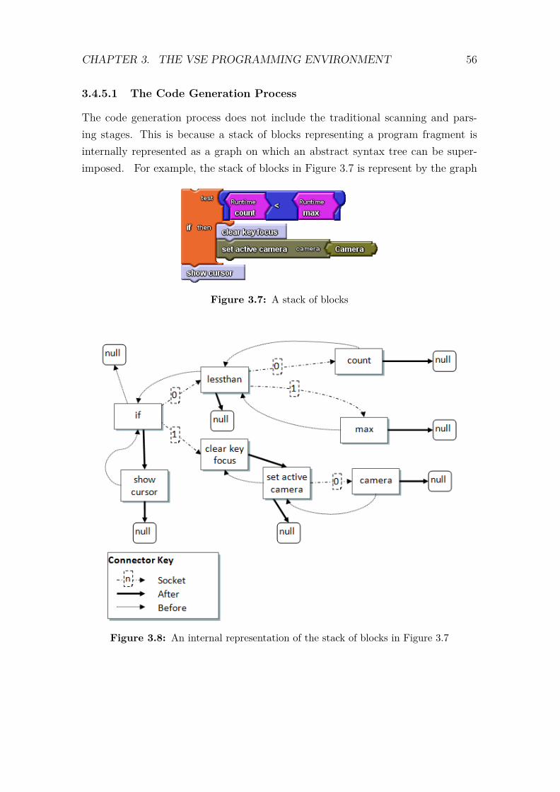
CHAPTER 3. THE VSE PROGRAMMING ENVIRONMENT 56
3.4.5.1 The Code Generation Process
The code generation process does not include the traditional scanning and pars-ing stages. This is because a stack of blocks representing a program fragment isinternally represented as a graph on which an abstract syntax tree can be super-imposed. For example, the stack of blocks in Figure 3.7 is represent by the graph
Figure 3.7: A stack of blocks
Figure 3.8: An internal representation of the stack of blocks in Figure 3.7

CHAPTER 3. THE VSE PROGRAMMING ENVIRONMENT 57
in Figure 3.8, from which the abstract syntax tree in Figure 3.9 is constructed byignoring the “before” edges and all edges that lead to vertices labelled “null.”
Figure 3.9: An abstract syntax tree extracted from Figure 3.8
In the abstract syntax tree shown in Figure 3.9, the “after” edges connect state-ments in sequence, whereas the “socket” edges connect internal parts of a singlestatement.
Algorithm 3.2 traverses the abstract syntax tree while printing out the corre-sponding Lua code. In the algorithm, fixedCodeList is an ordered list of Luacode fragments; socketList is an ordered list of socket edges appearing on anode; isEmpty(list) returns true if the list is empty and false otherwise; andnext(list) returns the next element in the list – the first call to next(list)returns the first list element, and the subsequent calls return the subsequent listelements. Note that line 10 is a recursive call.
The first call to Algorithm 3.2 normally passes the top-level block in a stack ofblocks. The algorithm completely generates Lua code for the current block beforeconsidering a block that is connected to the after connector. While generating Luacode for the current block, recursive calls to the algorithm are used to generate Luacode for any blocks connected to sockets appearing on the current block.
The VSE inherits the flexibility of OpenBlocks with respect to the connectedness ofblocks appearing on a page. Consequently, a page can have more than one top-levelblock. In such a case, the top-level block appearing in the topmost part of the page

CHAPTER 3. THE VSE PROGRAMMING ENVIRONMENT 58
1: while b 6= NULL do2: fixedCodeList ← getFixedCodeList(b)3: socketList ← getSockets(b)4:5: if (isEmpty(socketList)) then6: print next(fixedCodeList)7: else8: for all socket in socketList do9: print next(fixedCodeList)10: generateCode(getBlockAt(socket))11: print next(fixedCodeList)12: end for13: end if14:15: b ← getBlockAfter(b)16: end while
Algorithm 3.2: generateCode(Block b)
is processed first. If there is more than one such block, the leftmost of these blocksis processed first. If both the vertical and horizontal placement of top-level blockscoincide, the order of processing such top-level blocks is random.
The other problem emanating from non-insistence on connectedness is that somesockets can be left without plugs when the code generator module is evoked. Thenext section discusses how this problem is resolved.
3.4.5.2 Code Generator Warnings
The OpenBlocks system guards against the connection of code fragments into asyntactically invalid program. It does not, however, control how a user discon-nects blocks. One consequence of this is that some socket connectors might not beconnected to any blocks when the code generator module is evoked.
One of the functions of the block verifier module in Figure 3.3 (on page 45) is to lookfor blocks with empty sockets. If such blocks are found, and have not already beenhighlighted in red to signify compile-time errors, they are highlighted in yellow inorder to warn the user of potential logical errors emanating from the empty sockets.

CHAPTER 3. THE VSE PROGRAMMING ENVIRONMENT 59
A program with these warnings still compiles. The missing blocks in the socketsare replaced by default values, shown in Table 3.1, in the generated Lua code.
Type of missing block Default Lua valuenumber 0integer 0string "" (empty string)boolean falselist {} (empty list)
the rest nil
Table 3.1: Default values for missing blocks
This design prevents forcing the user to connect blocks in the empty sockets, incase the user omits the blocks to imply the default values. The user is howeverwarned, in case the omission is accidental.
The next section discusses problems that may arise due to the flexibility in namingvariables and procedures/functions.
3.4.5.3 Resolving Potential Naming Conflicts
The OpenBlocks system does not impose any syntactic rules on identifiers; and thusthe user is free to compose variable and procedure names using any combinationof characters available from his/her keyboard. Furthermore, variables of differenttypes are represented by blocks having different connector kinds and shapes in orderto visually suggest their incompatibility. Since a Boolean and a number variable,for example, are visually represented by incompatible blocks, there is no need forpreventing a user from giving the same name to both variables. Unique visualidentification is derived from the combination of the textual label and the shape ofthe block.
The OpenBlocks system only prevents a user from declaring more than one variableof the same type using the same name. Variables of different types may use thesame name. This behaviour is inherited by our VSE partly because it is expensiveto check against the reuse of an identifier name across multiple types; and the reuseof identifier names across different types is less restrictive to the user.
CHAPTER 3. THE VSE PROGRAMMING ENVIRONMENT 60
The code generator transforms the free-styled identifiers to syntactically correct Luaidentifiers by replacing any illegal character with the sequence _charcode, wherecharcode is the ASCII character code for the illegal character. An exception is thespace character, which is replaced by an underscore character only, instead of thesequence _32. This scheme was adopted in order to partially preserve the meaningof identifiers in the generated Lua code, in case an expert Lua programmer willwant to modify the Lua code.
The potential name conflicts among variables of different types are resolved byprefixing the variable names with a code that identifies the type of the variable.This also makes the Lua code more readable since the intended type of a variableis made explicit by the prefix of the variable name.
The next section discusses errors caused by deletion of blocks representing variable,procedure and function definitions.
3.4.5.4 Identifier Definition Errors
The OpenBlocks system supports the declaration of variables, lists, procedures andfunctions. There are blocks that are used to declare variables, lists, procedures andfunctions. Once a declaration has been made, by dragging a declaration blockonto a page, the system automatically creates blocks for generating other blocksfor manipulating the declared entity. These new blocks are used, for example, forsetting the value of a variable and calling a procedure or a function.
A declaration block can be deleted from a page when its corresponding manip-ulation blocks are still appearing on a page. This causes a situation similar toan attempt to reference a variable or a procedure that has not been declared, instatically typed textual programming languages.
One approach to resolving this problem would be to automatically delete the ma-nipulation blocks appearing on a page whenever a corresponding declaration blockhas been deleted. This would be inconvenient if, for example, the deletion wasaccidental. If this approach is adopted, the accidental deletion cannot be rectifiedby simply replacing the deleted declaration block. All the instances of the manip-ulation blocks would also need to be redrawn, on the page, and reconnected to therest of the program.
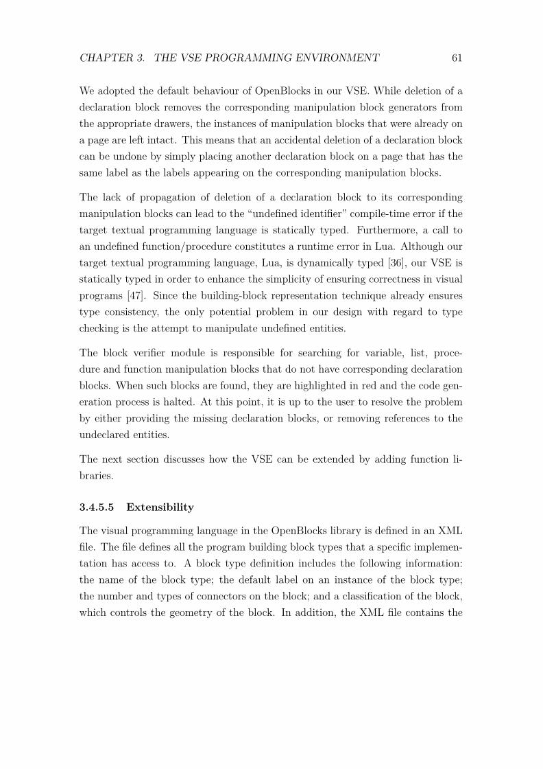
CHAPTER 3. THE VSE PROGRAMMING ENVIRONMENT 61
We adopted the default behaviour of OpenBlocks in our VSE. While deletion of adeclaration block removes the corresponding manipulation block generators fromthe appropriate drawers, the instances of manipulation blocks that were already ona page are left intact. This means that an accidental deletion of a declaration blockcan be undone by simply placing another declaration block on a page that has thesame label as the labels appearing on the corresponding manipulation blocks.
The lack of propagation of deletion of a declaration block to its correspondingmanipulation blocks can lead to the “undefined identifier” compile-time error if thetarget textual programming language is statically typed. Furthermore, a call toan undefined function/procedure constitutes a runtime error in Lua. Although ourtarget textual programming language, Lua, is dynamically typed [36], our VSE isstatically typed in order to enhance the simplicity of ensuring correctness in visualprograms [47]. Since the building-block representation technique already ensurestype consistency, the only potential problem in our design with regard to typechecking is the attempt to manipulate undefined entities.
The block verifier module is responsible for searching for variable, list, proce-dure and function manipulation blocks that do not have corresponding declarationblocks. When such blocks are found, they are highlighted in red and the code gen-eration process is halted. At this point, it is up to the user to resolve the problemby either providing the missing declaration blocks, or removing references to theundeclared entities.
The next section discusses how the VSE can be extended by adding function li-braries.
3.4.5.5 Extensibility
The visual programming language in the OpenBlocks library is defined in an XMLfile. The file defines all the program building block types that a specific implemen-tation has access to. A block type definition includes the following information:the name of the block type; the default label on an instance of the block type;the number and types of connectors on the block; and a classification of the block,which controls the geometry of the block. In addition, the XML file contains the

CHAPTER 3. THE VSE PROGRAMMING ENVIRONMENT 62
following: a specification of how to group blocks into families5 and drawers; andthe initial division of the scripting area into pages. Henceforth, we refer to thisXML file as the language defining XML file. A document type definition (DTD)for the language defining XML file is presented in Appendix A (on page 97).
The OpenBlocks library does not include a code generator; and consequently, theXML file does not include any specification on how to generate a target textualprogram. The OpenBlocks library, however, has the capability to extract languagespecific information from the language defining XML file. This language specificinformation is declared using a special tag in the XML file.
The design of the VSE code generator is divided into two parts. The first part,which we call the core, handles all the blocks that are standard in our visual lan-guage. These blocks include: blocks for building algebraic expressions; blocks forspecifying flow control; blocks for declaring and manipulating variables, lists, pro-cedures and functions; and blocks representing constants. The other part of thecode generator processes blocks representing calls to the game engine’s Lua libraryfunctions.
We designed the core of the code generator to be inextensible. The specificationsof blocks in the core are still defined in XML file; however, there is a tight couplingbetween the block definitions and the code generator core. This was done deliber-ately to prevent ad hoc changes to the semantics of our visual language, since suchchanges would detract from the learnabilty of the VSE’s visual language.
The other part of the code generator processes blocks representing Lua libraryfunctions. This part needs to be extensible because we anticipate changes to thegame engine’s Lua library as the game engine gains popularity. We thus decidedto place the Lua code fragments, discussed in Algorithm 3.2 (on page 58), in thelanguage defining XML file, for all blocks representing calls to the game engine’sLua library functions. The getFixedCodeList(b) function in Algorithm 3.2 (onpage 58) extracts the Lua code fragments from the language specific property el-ements of XML nodes representing blocks representing calls to the game engine’s
5A block family is a set of blocks in which any instance appearing on a page can be switchedwith any other member in the set without having to delete the block and dragging a new instancefrom a block drawer.

CHAPTER 3. THE VSE PROGRAMMING ENVIRONMENT 63
Lua library functions. New blocks representing calls to the library functions canthus be added to the XML file without the need to modify the code generator; sim-ilarly, blocks representing calls to library functions can be deleted from the XMLfile without the need to modify the code generator.
3.4.6 Persistent Storage of Visual Programs
The OpenBlocks library has functionality for generating XML text representingthe state of the entire script editing area. This XML text contains information onthe state of block drawers and the state of pages. This XML text can be saved ina text file; and later on used to reload a visual program.
When loading a visual program, the OpenBlocks system parses XML text repre-senting a visual program into a document object model (DOM) [5] tree. The DOMtree is then processed further to obtain graphs representing stacks of blocks, suchas the one shown in Figure 3.8 (on page 56).
StarLogo TNG version 1.2, which is based on the OpenBlocks library, saves eachcomplete visual program in one XML file. This means that whenever a visualprogram is loaded, the entire DOM tree has to be loaded and kept in main memoryuntil the DOM tree is fully processed to generate the graphs representing a visualprogram. This arrangement is sufficient in StarLogo TNG 1.2 since each visualprogram manipulates only one scene.
Our VSE, on the other hand, supports the development of visual programs thatmanipulate multiple scenes. We extended the OpenBlocks system to allow thegeneration of XML text representing scene objects. This XML text is added tothe XML text representing blocks. We also include XML text representing GUIs,their widgets, and event handler names, in the XML text that needs to be saved.If all this information was saved in a single XML file, and reloaded all at once, theresulting DOM tree would too large to fit in main memory6 if each scene has alarge amount of visual code.
Figure 3.10 shows the division of a single project’s XML text into multiple files.Each project is stored in at least three files. The project file is an XML file that
6The upper limit was set at 256 MB during testing.

CHAPTER 3. THE VSE PROGRAMMING ENVIRONMENT 64
stores file paths to all the other XML files in the project. The project file alsorecords the files holding the section of visual program that was displayed in thescript editing area at the time the visual program was saved. The main file holdsthe part of the visual program that is displayed in the GUI pages for the currentproject. A scene file holds part of the program pertaining to a single scene.
Figure 3.10: Files of a VSE program
When loading a visual program, the project file is loaded first. A project objectis created from the contents of the project file. The project object then locatesthe main file; opens it; and parses it to create a DOM tree. The project objectthen locates the scene that was open when the program was last saved; and parsesits contents into another DOM tree. The two DOM trees are then merged andpassed to the OpenBlocks subsystem for the final loading of the visual programrepresented by this merged DOM tree.
Using this technique optimises memory usage by making sure that only the scenethat the user is currently working on is loaded; and the other scenes are purgedfrom memory. GUI pages are always displayed because any scene can refer to anyGUI in the program.
The VSE should therefore be able to handle larger visual programs than StarLogoTNG, at least in theory.

CHAPTER 3. THE VSE PROGRAMMING ENVIRONMENT 65
3.5 Chapter Summary
In this chapter, we discussed an overview of the development process of games thatare executable on the Myoushu game engine. The lack of an IDE and the syntaxburden imposed by the textual Lua programming interface motivated the designand development of an IDE, with a visual scripting language.
The IDE, which we call the VSE, is based on the OpenBlocks library. The VSEpurports to lower the barriers to programming by representing programs usingbuilding blocks that connect only in ways that guarantee syntactically correct pro-grams. The VSE also inspects various resource files, such as scene files and GUIlayout files, and automatically generates program building blocks for manipulatingtheir content; thus taking the drudgery of manually inspecting these files from theuser.
The OpenBlocks library was extended to, among other things, provide: extra con-nector shapes that enhance the expressiveness of the visual language without havingto reuse connectors in different conflicting contexts; copy and paste functionalitythrough context sensitive pop-up menus; and a mechanism to support the treat-ment of procedures and functions as first class types – a functional programmingconcept.
It was observed that the freedom of placing blocks on a page without connectingthem to any other blocks is useful because it allows programs to be built in a moreflexible manner. This can, however, lead to some blocks having empty sockets,representing missing data, at compile-time. Default values are used in such cases;however, the user is warned in case the default behaviour was not intended.
We also observed that deleting blocks can introduce compile-time errors if a decla-ration block is deleted while the page still has blocks that refer to the entity whosedeclaration block has been deleted. Such blocks, whose corresponding declarationblocks have been deleted, are highlighted in red at compile-time; and cause thecode generation process to be halted prematurely, to avoid generating incorrectLua code.
Unlike StarLogo TNG 1.2, which is also based on the OpenBlocks library, theVSE supports programs with multiple scenes; and thus the VSE should be able to

CHAPTER 3. THE VSE PROGRAMMING ENVIRONMENT 66
cope with much larger visual programs than those that StarLogo TNG can handle.Consequently, VSE programs are saved in multiple files which are selectively loadedto reduce the main memory footprint.
To demonstrate the fitness of purpose of the VSE, the next chapter discusses thedevelopment of an educational game that was previously scripted directly in Lua.

Chapter 4
Example of Usage: Journey to theMoon
This chapter discusses the testing of the VSE through the implementation of aneducational game, called Journey to the Moon. At the time of testing, there wasalready an implementation of this game, whose scripts were created directly in Lua.The goal of the testing was to verify that we could reproduce the logic of thesescripts using the VSE’s visual programming language. We successfully reproducedthe scripts, even though we encountered some issues that prompted changes to theoriginal design of the VSE.
4.1 Introduction
Journey to the Moon is an educational game that was developed by Chamber-lain [61]. The target audience of the game is grade one pupils. A player of thegame does not directly control the main character in the game. The main char-acter, nevertheless, interacts with the player through text and audio. The maincharacter presents the player with problems, which are displayed textually. Theproblems involve simple arithmetic and language. The player provides answers bytyping them using the keyboard. If the player answers five questions correctly, ananimation is played and the game proceeds to the next state. If a wrong answeris provided, the same question is repeated for up to three times before a differentquestion is asked.
67

CHAPTER 4. EXAMPLE OF USAGE: JOURNEY TO THE MOON 68
The storyline of the game is as follows: A scientist receives a message to go tothe moon and investigate some mystery. The story is divided into two scenes. Inthe first scene, the scientist is in his laboratory when he receives the message. Hisgoal for the first scene is to get into a spaceship and take off. He discovers thatmost of his equipment is malfunctioning, and needs to correct the malfunction bysolving some simple arithmetic and language problems. The player’s task is to solvethese problems on behalf of the scientist. Figure 4.1 is a screenshot from the gameshowing one of the problems that the player has to solve to unlock a garage doorso that the spaceship can take off.
Figure 4.1: A screenshot from Journey to the Moon (adapted from [61], page 90)
The first scene ends with the spaceship taking off. In the second scene, the spaceshipis flying through space. The spaceship encounters several asteroids in its flightpath. The scientist has to dodge or destroy the asteroids to avoid damaging the

CHAPTER 4. EXAMPLE OF USAGE: JOURNEY TO THE MOON 69
spaceship’s protective shield. The player has to solve sets of problems to enablethe scientist to dodge or destroy the asteroids. Each problem now has a time limit.If the time limit expires before the player provides the correct answer, the asteroidhits the spaceship. If the spaceship is hit by at least three asteroids, the shield iscompletely destroyed, the mission is aborted, and the second scene restarts.
Journey to the Moon is one of the games that were developed to test the Myoushugame engine. It was selected as our test case because it makes use of more than80% of the game engine’s capabilities [61]. The remaining capabilities, namely net-working and replays can easily be added to the VSE by adding appropriate blocksand drawers specifications to the language defining XML file that we discussed inSection 3.3 (on page 40).
4.2 The Goals of Testing
The main aim of scripting Journey to the Moon in the VSE was to confirm thatthe VSE is capable of supporting the specification of logic in VEs developed for theMyoushu engine. The objective is not to test the Myoushu game engine. Rather, wecheck whether the VSE can support visual expression of game logic, and whetherthe visual expressions can be converted to Lua code that can be executed by thegame engine.
We did not deem it necessary to conduct a user study because our VSE is based onthe OpenBlocks framework, which was already adequately evaluated [16, 20]. Sinceour VSE does not portray a significant departure from the OpenBlocks’ visual rep-resentation technique, we anticipate that our VSE’s visual programming languagewill be equally usable.
Our testing was focused on verifying that the design objectives set out in Section 3.2(on page 39) are met. In particular, we sought to verify that:
1. the majority of scripting commands and expressions are represented by graph-ical elements, so that scripting can be done using a predominantly drag-and-drop interaction style;

CHAPTER 4. EXAMPLE OF USAGE: JOURNEY TO THE MOON 70
2. programmable scene and GUI artefacts are represented by graphical ele-ments that are compatible with the graphical elements in 1. These visualelements, representing programmable artefacts, should be automatically gen-erated upon the user loading the corresponding resource files.
3. the user is presented with a simple-to-use interface for managing scenes andtheir content;
4. the user is presented with a simple-to-use interface for managing GUIs andtheir content;
5. the process of exporting scripts and other resources to the game engine forexecution is automated; and
6. the VSE is able to generate Lua scripts from the graphical programs men-tioned in 1. The Lua code should be human-readable to the extent that itcan be modified by a skilled Lua programmer.
In addition to these objectives, we also sought to verify that the visual language isextendable without needing to reprogram the code generator. The extensions aremainly in the form of addition of new blocks representing new library functions.These extensions need to be completely expressible in the language defining XMLfile.
The next section discusses how the scripting of Journey to the Moon was tackledto ensure that the goals of testing, discussed above, are met.
4.3 Testing Strategy
There were two aspects to the testing of the VSE. The first concerns the compositionof visual programs. We sought to verify that the semantics that was previouslyexpressed directly in Lua could be also be expressed by the VSE’s blocks.
The second aspect relates to the semantic equivalence of Lua scripts generated fromthe VSE’s visual programs and those which were previously created directly. Thescripts that were previous expressed directly in Lua had no syntax errors, sincethe Myoushu engine’s Lua interpreter was able to parse and execute the scripts.

CHAPTER 4. EXAMPLE OF USAGE: JOURNEY TO THE MOON 71
Thus, checking for absence of syntax errors in the generated Lua code was one ofthe steps towards verifying the equivalence with the original Lua code.
The generated Lua code was tested for syntax errors using a third-party pretty-printer, called LuaFormat [1]. We integrated LuaFormat into the VSE. The VSE’scode generator runs LuaFormat on any Lua file that it generates. LuaFormat’sprimary function is to transform Lua code that is not correctly formatted (indented)to nicely formatted Lua code. LuaFormat includes a Lua parser, and prematurelystops outputting formatted Lua code if the input Lua file contains any syntax error.
We exploited the behaviour of LuaFormat when processing Lua code with syntaxerrors to check the Lua files, generated by the VSE, for syntax errors. Each group ofblocks, whose generated Lua code was under test, was linked to a procedure block1.Figure 4.2 shows an example of connecting blocks under test to a procedure block inorder to detect syntax errors. The resulting formatted code is shown in Listing 4.1.Note that a function definition in Lua is terminated by the end keyword. If anyof the three blocks below the procedure block, labelled Test blocks, resulted intothe generation of Lua code that had syntax errors, LuaFormat would have stoppedprinting the formatted code before the end keyword.
Figure 4.2: Wrapping blocks under test in a procedure to detect syntax errors
1 function proc_Test_blocks()2 guiGetWidget("StaticImageDash"):setCaption("Question");3 end
Listing 4.1: Formatted Lua code generated from the blocks in Figure 4.2
1A procedure block is used for defining functions and procedures.

CHAPTER 4. EXAMPLE OF USAGE: JOURNEY TO THE MOON 72
We did not create the entire game from scratch. We reused artefacts such as scenefiles, GUI layout files, sound files and educational content files. Recall that theVSE is not tasked with creating a game’s visual artefacts like game characters andGUIs. There are graphical editing tools for creating these, such as Blender [10] forcreating scenes and its objects and characters, and MyGui’s Layout Editor [13] forcreating GUIs that are used for dialog inside a game’s VE. We refer to the collectionof scene files, GUI layout files, sound files and educational content files as resourcefiles.
The game scripting process involved creating scripts controlling GUIs used in thegame’s VE. GUI controlling scripts mainly specify code to be executed when a userinteracts with a widget on the GUI; for example, what should happen when a userclicks on a particular button.
We tested the GUI scripting capability of the VSE by first loading the five GUIlayout files defined for Journey to the Moon. The original Lua files for the GUIswere retrieved, and we tried to recreate the logic using the VSE’s block language.The goal was to verify that each referenced widget was represented by a block inthe VSE. We also sought to check that the VSE automatically generated eventhandler definition blocks for all the event handlers that were specified in the GUIlayout files.
The scene scripting capability of the VSE was tested in a manner similar to thatfor testing GUI scripting capability. Scene files (Dotscene files) were first loaded,and then we tried to imitate the code in the scene’s corresponding Lua scriptfile. The process was slightly different from the GUI’s. Loading a scene doesnot result in automatic generation of blocks for manipulating the scene content.Blocks for manipulating scene objects are generated upon marking the objects asprogrammable in the form shown in Figure 4.3. We sought to verify that all objectsreferenced in the original Lua script file for a particular scene are available fromthe form in Figure 4.3; and that upon marking an object as programmable, all ofits defined animations are automatically represented by appropriate blocks.
Sound files are handled differently. There is no file that lists all sound files usedin a game. However, all the sound files used in a game are typically placed inone folder. The testing in this case sought to verify that the VSE automatically
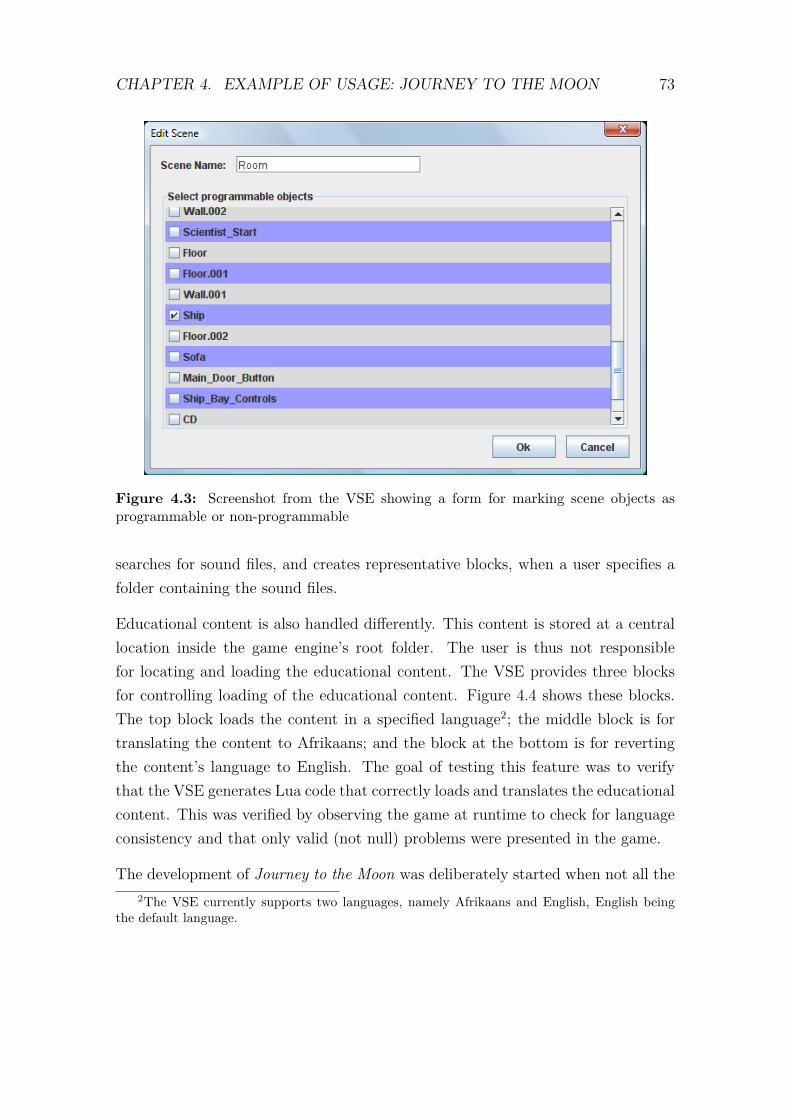
CHAPTER 4. EXAMPLE OF USAGE: JOURNEY TO THE MOON 73
Figure 4.3: Screenshot from the VSE showing a form for marking scene objects asprogrammable or non-programmable
searches for sound files, and creates representative blocks, when a user specifies afolder containing the sound files.
Educational content is also handled differently. This content is stored at a centrallocation inside the game engine’s root folder. The user is thus not responsiblefor locating and loading the educational content. The VSE provides three blocksfor controlling loading of the educational content. Figure 4.4 shows these blocks.The top block loads the content in a specified language2; the middle block is fortranslating the content to Afrikaans; and the block at the bottom is for revertingthe content’s language to English. The goal of testing this feature was to verifythat the VSE generates Lua code that correctly loads and translates the educationalcontent. This was verified by observing the game at runtime to check for languageconsistency and that only valid (not null) problems were presented in the game.
The development of Journey to the Moon was deliberately started when not all the2The VSE currently supports two languages, namely Afrikaans and English, English being
the default language.
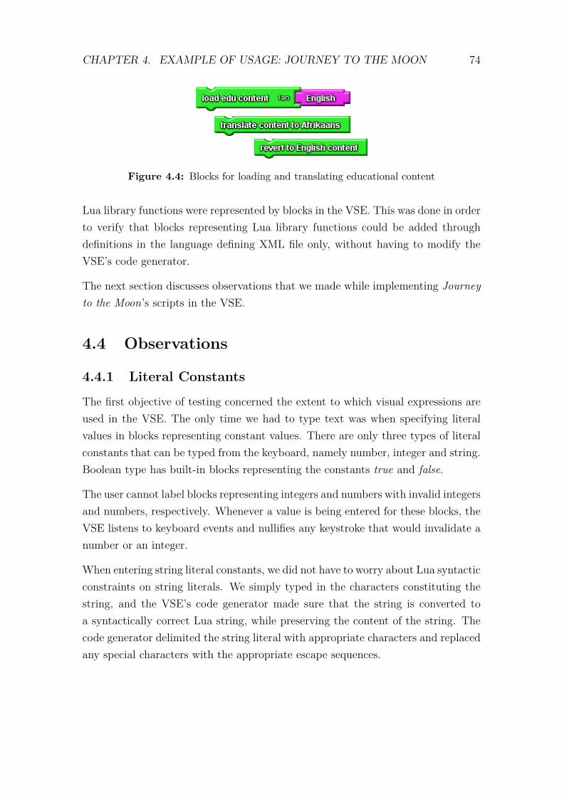
CHAPTER 4. EXAMPLE OF USAGE: JOURNEY TO THE MOON 74
Figure 4.4: Blocks for loading and translating educational content
Lua library functions were represented by blocks in the VSE. This was done in orderto verify that blocks representing Lua library functions could be added throughdefinitions in the language defining XML file only, without having to modify theVSE’s code generator.
The next section discusses observations that we made while implementing Journeyto the Moon’s scripts in the VSE.
4.4 Observations
4.4.1 Literal Constants
The first objective of testing concerned the extent to which visual expressions areused in the VSE. The only time we had to type text was when specifying literalvalues in blocks representing constant values. There are only three types of literalconstants that can be typed from the keyboard, namely number, integer and string.Boolean type has built-in blocks representing the constants true and false.
The user cannot label blocks representing integers and numbers with invalid integersand numbers, respectively. Whenever a value is being entered for these blocks, theVSE listens to keyboard events and nullifies any keystroke that would invalidate anumber or an integer.
When entering string literal constants, we did not have to worry about Lua syntacticconstraints on string literals. We simply typed in the characters constituting thestring, and the VSE’s code generator made sure that the string is converted toa syntactically correct Lua string, while preserving the content of the string. Thecode generator delimited the string literal with appropriate characters and replacedany special characters with the appropriate escape sequences.

CHAPTER 4. EXAMPLE OF USAGE: JOURNEY TO THE MOON 75
4.4.2 Block-to-Function Mapping
Block-to-function mapping is the assignment of Lua function calls to VSE blocks.We noted that Myoushu’s Lua function library had numerous functions. Further-more, the original Lua scripts for Journey to the Moon had direct calls to Myoushu’sC function library. If each library function was to be represented by a block in theVSE, the resulting number of building blocks would be overwhelming. The largenumber of blocks would detract from the learnability of the VSE, thus defeatingour goal of lowering the barriers to scripting.
We observed that a significant portion of the library functions, both Lua and C,could be considered helper functions, whose call fulfil preconditions for anotherfunction’s call. We created a new library, which encapsulates a sequence of calls tohelper functions and the main function call into a single function call.
Listing 4.2 is an example of a situation that required a higher level library functionthat encapsulates lower level calls. Listing 4.2 is an excerpt from an original Luascript for controlling the main menu in Journey to the Moon. The code fragment’stask is to add an entry to a game log entity, gSessionsEntity. A log entity’s entryis a one-dimensional Lua table. The elements of the table are strings.
1 -- Create the new session2 local values = Myoushu.ListValue()3 local val = Myoushu.Value()4 gSessionTimestamp = os.time()5 val:set(gSessionTimestamp)6 values:push_back(val);7 val:setString(gPlayerName)8 values:push_back(val)9
10 gSessionsEntity:addEntry(values)
Listing 4.2: An excerpt from an original Lua script file controlling the main menu (aGUI) in Journey to the Moon

CHAPTER 4. EXAMPLE OF USAGE: JOURNEY TO THE MOON 76
We created a single high-level library function to implement the task being per-formed by Listing 4.2. The new library function is shown in Listing 4.3. Thefunction accepts two parameters, namely entity and itemList. Here, entity isthe log entity to which a new entry is being added, and itemList is the new entry,that is, a one-dimensional Lua table of strings.
1 function _add_log_entry(entity, itemList)2 local values = Myoushu.ListValue()3 local val = Myoushu.Value()4 local n = _list_length(itemList)5
6 for i = 1, n do7 val:setString(tostring(itemList[i]))8 values:push_back(val)9 end
10
11 entity:addEntry(values)12 end
Listing 4.3: A more task-oriented library function implementing the task in Listing 4.2
After implementing this new library function, the task in Listing 4.2 could then bevisually expressed using six blocks, as shown in Figure 4.5.
Figure 4.5: Adding an entry to log entity

CHAPTER 4. EXAMPLE OF USAGE: JOURNEY TO THE MOON 77
4.4.3 Variables and Connector Shapes
In Section 3.4.5.5 (on page 61) we mentioned that blocks for defining and ma-nipulating variables are part of the core of the VSE’s block language. However,during the development of the scripts of Journey to the Moon, it became apparentthat the VSE should support the addition of blocks for defining and manipulatingvariables through the language defining XML file. If a library function accepts anactual parameter of a new type, then there is a need to add blocks for declaringand manipulating variables of the new type.
As an example, reconsider the code fragment in Figure 4.5. In the figure, the blocklabelled gSessionsEntity reports the value of a log entity variable. If we did notprovide blocks for defining and manipulating log entity variables, the only way toaccess a log entity would be through the get log entity block in Figure 4.6. The
Figure 4.6: Block for retrieving or creating a log entity
get log entity block represents a function call that retrieves a log entity havingthe properties represented by the three blocks connected to it. If such a log entitydoes not exist, the function creates a new log entity and returns the new log entity.Although it is sufficient to use this function call block every time we reference a logentity, the resulting code would be unnecessarily verbose. The code in Figure 4.5,for example, degrades to the code in Figure 4.7.
Based on this observation, we implemented two changes to the VSE. First, we mod-ified the code generator to allow complete specification of variable declaration andmanipulation blocks in the language defining XML file. By complete specification,we mean the specification of the visual appearance and behaviour of the block, aswell as the translation into Lua code. Secondly, we created nine additional blockconnector shapes, bringing the total to thirty. Of these connectors, twenty fivehave already been used in the current implementation of the visual programminglanguage. The remaining five are reserved for future use.

CHAPTER 4. EXAMPLE OF USAGE: JOURNEY TO THE MOON 78
Figure 4.7: The equivalent of the code in Figure 4.6 in the absence of log entity variables
We included unused connector shapes because adding a new connector shape in-volves two steps, the first of which requires recompilation of the VSE’s source code.In the first step, the geometry of the shape is defined. Once the geometry has beendefined, the VSE’s source code has to be recompiled. The second step assigns aname to the new connector shape. This is done in the language defining XML file,and does not require recompilation of the VSE’s source code.
4.4.4 GUIs and Memory
Editing visual scripts for controlling GUIs was found to be memory intensive. Whena user loads a GUI layout file into the VSE, the VSE automatically creates blocksrepresenting all widgets on the GUI, and blocks for defining and evoking an eventhandler for each declared event handler. These blocks are placed in a drawer;and, except for the event handler definition blocks, these blocks act as factoriesfor generating an infinite number of copies. Thus loading a GUI layout file resultsin the automatic creation of a significant number of blocks, even before the userstarts composing the visual script for the GUI. We do not allow the user to markwidgets as programmable and non-programmable, as is the case with scene objects,because a typical GUI controlling script makes reference to the majority of theGUI’s widgets.
Figure 4.8 shows part of the visual script controlling the main menu GUI in Jour-ney to the Moon. The left side shows some of the blocks representing widgets on

CHAPTER 4. EXAMPLE OF USAGE: JOURNEY TO THE MOON 79
the main menu GUI. These blocks are from the MainMenu drawer, which was au-tomatically created when we loaded the GUI layout file for the main menu. Thememory footprint of this script was 33.4 MB3.
Figure 4.8: GUI widget blocks in a drawer and part of a GUI script
This observation suggested that the project organization model discussed in Sec-tion 3.4.6 (on page 63) would lead to excessive memory usage. Consequently, wemodified the model, as shown in Figure 4.9. The actual GUI code is no longercontained in the main file. The main file only maintains GUI metadata. EachGUI’s script is individually stored in a separate file. With this new arrangement,the user can choose which of the project’s GUIs to display in the workspace, thus
3We measured this using NetBean’s Profiler. This memory estimate is for the GUI code only,and excludes the memory consumed by the VSE (with the block language loaded), which was22.1 MB.
CHAPTER 4. EXAMPLE OF USAGE: JOURNEY TO THE MOON 80
controlling the amount of memory used by the VSE at any given time. We rec-ommend displaying at most one GUI script at a time. Functions, procedures andglobal variables and lists defined in the hidden GUI pages are accessible from aspecial drawer, labelled _externals.
Figure 4.9: Modified project organization
4.4.5 Routine Tasks
We observed that some tasks were routine in specific types of scripts. For example,a GUI script that includes event handlers has to register all the event handlerswith the game engine. We excluded such tasks from the programming interface,and let the code generator automatically generate code for such routine tasks.This translates to both lowering the barriers to scripting, as well as enhancing theperformance of the VSE by excluding the extra blocks associated with routine code.

CHAPTER 4. EXAMPLE OF USAGE: JOURNEY TO THE MOON 81
4.5 Chapter Summary
In this chapter, we discussed the testing of the VSE through the implementationof an educational game, called Journey to the Moon. The implementation of thegame was successful; however, we encountered some problems which prompted usto change the original design of the VSE.
We discovered that we could not map the game engine’s library functions to VSEblocks in a one-to-one fashion, lest we end up with too many blocks representinglibrary function calls, which would compromise learnability of the system.
We also learnt that addition of blocks representing library function calls can triggerthe need for new data types, and consequently new variable types. We modifiedthe code generator to allow specification of new variable types in the languagedefining XML file. Another direct consequence of this was the need for extra blockconnector shapes, which we created.
We also noted that GUI visual scripts were memory intensive. We thus modifiedthe structure of projects to make it possible for GUI script pages to be hidden(and thus unloaded from memory) to control the memory footprint of the VSEapplication.
Finally, we observed that some tasks in the scripts were routine. We excluded suchtasks from the visual programming interface, and let the code generator automat-ically generate code for such tasks.

Chapter 5
Results and Conclusions
5.1 The VSE and the Research Objective
The main objective of our research was to investigate methods to lower the barrierto the development of VEs based on the Myoushu game engine. We focused onthe addition of a VPE layer on top of the pre-existing Lua scripting interface. Wediscuss how the VSE meets this objective in Section 5.1.1 through Section 5.1.6.Section 5.1.7 discusses how the question of extensibility has been addressed.
5.1.1 Elimination of the Syntax Burden
The VSE provides the programmer with all the necessary program building blocks,so that the programmer does not have to type any syntactic structure. A programis composed, mostly, by dragging, dropping and connecting blocks. Blocks can onlybe connected in ways that assure syntactically correct programs. The connective-compatibility of blocks is visually suggested to the programmer by using a plug-socket connector metaphor. A plug and a socket can connect only if they havecomplementary shapes.
It may be argued that the plug-socket connector metaphor plays the same roleas syntax error highlighting in IDEs such as Eclipse [12] and NetBeans [14]. Weconsider the plug-socket connector metaphor to be superior, since it prevents syntaxerrors from occurring; rather than allowing an error to occur, and then inform the
82

CHAPTER 5. RESULTS AND CONCLUSIONS 83
programmer of the syntax error. This idea is in line with the ancient wisdom thatprevention is better than cure.
The VSE blocks hide the syntactic structure of the programming constructs theyrepresent. By using these blocks, a programmer cannot, for example, forget toterminate the body of an if statement, in Lua, by an end keyword.
The VSE helps the programmer prevent syntax and logical errors caused by typo-graphical errors. Listing 5.1 shows a Lua code fragment that was supposed to gen-erate ten random integers and store them in the table, nums. The while loop in thecode fragment cannot terminate because the value of num is never changed withinthe body of the loop. On line 5, the programmer wanted to write num = num + 1,but accidentally typed nun = num + 1. This statement does not result in an “un-known identifier” error because variable definition is implicit in Lua, thus the firstrun through the loop defines a new global variable, nun. This logical error cannot
1 nums = {}2 num = 0;3 while (num < 10) do4 nums[num] = math.random(0, 10)5 nun = num + 16 end
Listing 5.1: A non-terminating loop caused by a typographical error
occur in the VSE, unless the variable nun was already explicitly defined at the timeof composing the loop. A variable name is typed only once, when defining thevariable. Subsequent references to the variable are made through variable getterblocks that are automatically generated by the VSE.
Blocks representing algebraic, relational and logical operators have sockets whichexplicitly indicate the relative positions of their operands. Each operand can be anexpression of arbitrary complexity. There is no possibility for ambiguity regardingwhich sub-expressions any given operator refers to. This eliminates the need forthe notion of operator precedence and parenthesis. The programmer can thus build
CHAPTER 5. RESULTS AND CONCLUSIONS 84
algebraic, relational and logical expressions without having to remember operatorprecedence rules of the operators involved, or having to worry about balancingparentheses in a complex expression.
The VSE does not enforce any syntactic constraints on identifiers. Programmerscan create identifiers using any combination of characters available from the key-board. The only restriction is that no two variables of the same type may be definedusing the same identifier. The novice programmer does not have to worry aboutusing only syntactically correct identifiers.
Finally, blocks representing string constants allow the string constants to be enteredin a direct manner. The programmer is never concerned about syntactic rules forstrings, such as: delimiting string literals with the appropriate special character,and using escape sequences in place of special characters.
5.1.2 Hidden Technical Jargon
The VSE’s visual programming language hides technical jargon associated with theMyoushu game engine, and 3D graphics in general. Consider the Lua statement inListing 5.2, for example. The statement moves a scene object, referred to by thename box01, forward by z units. Before the advent of the VSE, the programmerhad to understand how the Myoushu game engine represents scenes before writingcode to manipulate scene objects. In this example, the user would need to knowthat any scene object is contained in an object of type SceneNode; that the 3Dgeometry technical term for movement is translation; that translation is specifiedby a 3D vector and a transformation space; and that self-relative motion uses thetransformation space Myoushu.Node_TS_LOCAL. This would be too much materialto learn for someone new to programming and 3D VEs.
1 scene:getSceneNode("box01"):translate(0,0, z,2 Myoushu.Node_TS_LOCAL)
Listing 5.2: A move forward command
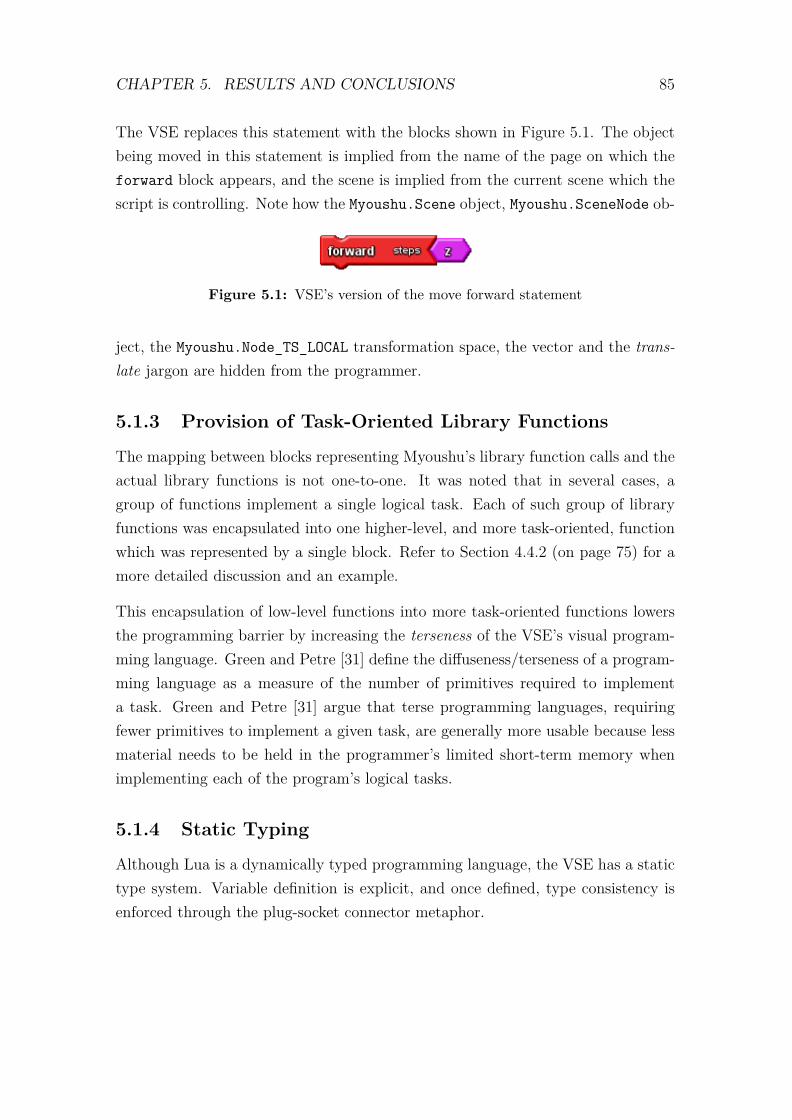
CHAPTER 5. RESULTS AND CONCLUSIONS 85
The VSE replaces this statement with the blocks shown in Figure 5.1. The objectbeing moved in this statement is implied from the name of the page on which theforward block appears, and the scene is implied from the current scene which thescript is controlling. Note how the Myoushu.Scene object, Myoushu.SceneNode ob-
Figure 5.1: VSE’s version of the move forward statement
ject, the Myoushu.Node_TS_LOCAL transformation space, the vector and the trans-late jargon are hidden from the programmer.
5.1.3 Provision of Task-Oriented Library Functions
The mapping between blocks representing Myoushu’s library function calls and theactual library functions is not one-to-one. It was noted that in several cases, agroup of functions implement a single logical task. Each of such group of libraryfunctions was encapsulated into one higher-level, and more task-oriented, functionwhich was represented by a single block. Refer to Section 4.4.2 (on page 75) for amore detailed discussion and an example.
This encapsulation of low-level functions into more task-oriented functions lowersthe programming barrier by increasing the terseness of the VSE’s visual program-ming language. Green and Petre [31] define the diffuseness/terseness of a program-ming language as a measure of the number of primitives required to implementa task. Green and Petre [31] argue that terse programming languages, requiringfewer primitives to implement a given task, are generally more usable because lessmaterial needs to be held in the programmer’s limited short-term memory whenimplementing each of the program’s logical tasks.
5.1.4 Static Typing
Although Lua is a dynamically typed programming language, the VSE has a statictype system. Variable definition is explicit, and once defined, type consistency isenforced through the plug-socket connector metaphor.
CHAPTER 5. RESULTS AND CONCLUSIONS 86
1 num = 02 nums = {}3 while num ~= maximum do4 nums[num] = num5 num = num + 1;6 end
Listing 5.3: A subtle logical error in Lua
Dynamic typing and implicit variable declaration in Lua can cause subtle logicalerrors, which a novice programmer might find hard to debug. Consider the programfragment in Listing 5.3, in which the author was trying to initialize a Lua tablewith values 1, 2, 3, · · · , maximum. At this point maximum is not defined. In Lua,any undefined variable has a default nil value. The value nil is the only value inLua’s Nil data type. Furthermore, Lua allows equality operations on arguments ofdifferent types; the result of such operations being true in the case of ~=, and falsein the case of ==. The while loop in Listing 5.3 thus runs forever until the systemruns out of memory and the program crashes.
Such a logical error is irreproducible in the VSE because each operator (includ-ing functions and procedures) enforces type consistency, and variable definition isexplicit.
5.1.5 Automatic Discovery of Programmable Elements
Lua scripts for controlling scenes and GUIs typically make reference to scene objectsand their associated animations, and GUI widgets and event handlers, respectively.When creating these Lua scripts directly (textually), the programmer has to man-ually examine XML files for scenes and GUIs to discover programmable content.XML files representing scenes (Dotscene files) typically contain hundreds of XMLnodes, thus searching for programmable element is an extra burden, and more soto a novice programmer.
The VSE has eliminated this burden by searching these files, on behalf of theprogrammer, for programmable content, and automatically creating blocks repre-

CHAPTER 5. RESULTS AND CONCLUSIONS 87
senting the programmable content in these files
5.1.6 Resource File Management
A Myoushu 3D VE typically comprises several resource files, including: Dotscenefiles, polygonal mesh model files, skeleton model files, collision mesh files, GUIlayout files, sound files, files containing shading and texture information, dialogtranslation files, educational content files and Lua script files. Maintaining theseresource files, and configuration files that point to the locations of these files, canbe a daunting task to a novice programmer.
The VSE has taken this drudgery away from the programmer. The VSE keepstrack of the resource files on behalf of the user; and is responsible for creating theconfiguration files when the programmer wants to test a VE on the game engine.
5.1.7 Extensibility
A secondary research objective concerned the extensibility of the VSE through theaddition (and removal) of blocks representing library function calls. We sought tosimplify the process of adding and removing blocks representing library functioncalls.
We have successfully decoupled XML specifications of the VSE’s visual program-ming language from the VSE’s code generator. New blocks representing new typesof variable and library functions can now be fully specified in an XML file thatstores the specifications of the VSE’s block language. The specifications of the newblocks embed instructions for the code generator module, which inform the codegenerator how to transform the blocks into the target Lua. Block specifications,representing variable types and library function calls, can thus be added to andremoved from the language defining XML file without requiring any changes to thecode generator.
The next section discusses the general limitations of the building-block visual pro-gram representation technique. The discussion is primarily based on our experiencewith the OpenBlocks framework.

CHAPTER 5. RESULTS AND CONCLUSIONS 88
5.2 Limitations of the Building Block Approach
The OpenBlocks framework has been successfully used to implement our VSE,which has lowered the barriers to the task of creating scripts for VEs based onthe Myoushu game engine. Despite this success, the building-block visual programrepresentation technique, which the OpenBlocks framework uses, has limitationsthat affect the scalability of visual programming languages that are purely based onthis representation technique. In this section, we discuss three of these limitations,and argue that the OpenBlocks framework cannot be used to implement an object-oriented general-purpose visual programming language.
5.2.1 Lack of Hierarchy
The plug-socket connector metaphor used on connector shapes makes it impossiblefor blocks to visually express is-a-kind-of relationships. An example of this prob-lem, concerning the representation of floating-point numbers and integers, has beendiscussed in Section 3.4.1.3 (on page 48). Both floating-point numbers and integersare kinds of numbers. These two kinds of numbers have additional properties thatare unique to each kind, which makes some situations demand the use of preciselyone kind. For example, counting is normally done using positive integers, whereasthe result of real number division is a floating-point value. It would seem most nat-ural to represent the two kinds of numbers using blocks with dissimilar connectorshapes to visually emphasize their distinct special properties.
If integer blocks use connector shapes that are different from those on blocks rep-resenting floating-point numbers, then all operators defined for floating-point num-bers cannot be applied to integers. The reason for this is that an operator forfloating-point numbers (for instance, the addition operator) would have socketsthat accept only other floating-point numbers. A different version of the operatorwould need to be defined for integers; and another that accepts an integer as itsleft side operand and a floating-point number as its right side operand; and yetanother version with a floating-point number as its left side operand and an integeras its right side operand. Thus each binary algebraic operator would need to havefour different versions. Each function that accepts a generalised number parameterwould also need to have two versions, one for integer parameters and the other for

CHAPTER 5. RESULTS AND CONCLUSIONS 89
floating-point parameters. This approach would result in an unnecessarily largenumber of blocks representing algebraic operators.
The solution that we adopted in our VSE was to use the same connector shapesfor integers and floating-point numbers. The blocks representing the two kindsof numbers are differentiated using colour. Connection of shapes involving inte-gers and floating-point numbers no longer follows the default plug-socket connectormetaphor. We added a rule that overrides the metaphor, namely: floating-pointnumber sockets accept both kinds of number plugs, whereas integer sockets onlyaccept integer plugs.1 This amounts to connector shape overloading, discussed byRoque in [54], which detracts from the learnability of the visual language.
The problem stems from the rigidity of the plug-socket connector metaphor. Asocket should not accept plugs of any type other than the type of the socket. Anexception to this rule are the polymorphic sockets, which generally accept plugs ofany kind; and polymorphic plugs, which generally fit in any socket kind.
This difficulty in expressing hierarchical relationships is not limited to the repre-sentation of numbers. In general, the plug-socket connector metaphor makes itimpossible for a visual programming language that is purely based on the building-block approach to visually express the object-oriented programming concept ofinheritance.
5.2.2 Connector Shapes
The idea behind using differentiated connector shapes in the plug-socket connectormetaphor is to visually suggest, to the programmer, the compatibility of blocks.The compatibility of complementary plugs and sockets should thus be readily dis-cernible at a glance, without undue effort. We believe that a building-block VPEhas a limit on the number of different connector shapes, beyond which some of theconnector shapes will start to appear too similar to be distinguishable at a glance.
The implication of this observation is that there is a stringent limit on the numberof data types that a building-block VPE can visually discriminate using the plug-socket connector metaphor. Thus the concept of user defined types is unlikely to be
1Note that connector shapes and connector kinds are different concepts. Although integersand floating-point numbers share a connector shape, their underlying connector kind is different.

CHAPTER 5. RESULTS AND CONCLUSIONS 90
feasible in VPEs that are purely based on the building-block visual representationtechnique and employ the plug-socket connector metaphor. It is thus not surprisingthat none of the three related VPEs that we surveyed has support for user definedtypes.2
5.2.3 Variable Scoping
The current design of the OpenBlocks framework’s GUI does not offer opportunityto implement variable scoping. This problem emanates from the way block drawersand pages are laid out on the GUI. A typical OpenBlocks’ GUI has several pageswhich are placed in a contiguous manner across the width of the screen. A blockfrom any drawer is accessible to any page. When a variable is declared, by dragginga variable declaration block onto a page, the OpenBlocks framework automaticallycreates blocks for manipulating the variable, and places these blocks in a dynamicdrawer that has the same name as the page on which the declaration block appears.Since a block from any drawer can be dragged and dropped onto any page on theGUI, the scope of any declared variable is global.
For small programs, the lack of local variables is not a major concern. However,the problem is worrisome in the context of function/procedure formal parameters.The OpenBlocks framework treats formal parameters as constant value parameters,and does not provide blocks for setting or changing the value of a formal parame-ter. These formal parameters are considered local to the function/procedure thatdeclares them, at least in theory. In practice, however, declaration of a formalparameter (by connecting a parameter block to a procedure block), results in theOpenBlocks framework creating a block for retrieving the value of the parameter.This retrieval block is placed in a dynamic drawer that is labelled with the samename as the page on which the parameter declaration block appears. Consequently,the parameter block can be dragged and dropped onto any page, and any locationwithin the page.
Figure 5.2 shows a formal parameter, test par, which is declared in the function2Recall that Alice does not use the plug-socket connector metaphor. We suspect that Alice’s
lack of support for user-defined types is due the use of built-in expression builders that ensure thesyntactic correctness of expressions. It would be impossible for user-defined types to be createdwithout updating the rules that the expression builders use.
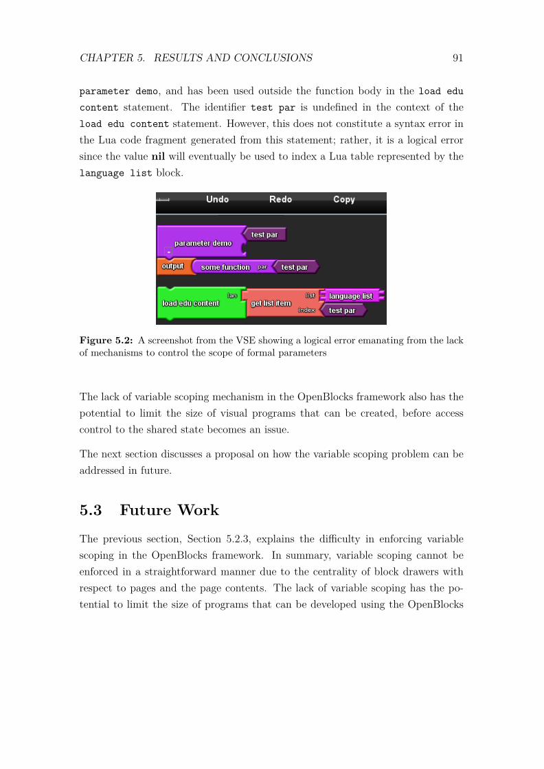
CHAPTER 5. RESULTS AND CONCLUSIONS 91
parameter demo, and has been used outside the function body in the load educontent statement. The identifier test par is undefined in the context of theload edu content statement. However, this does not constitute a syntax error inthe Lua code fragment generated from this statement; rather, it is a logical errorsince the value nil will eventually be used to index a Lua table represented by thelanguage list block.
Figure 5.2: A screenshot from the VSE showing a logical error emanating from the lackof mechanisms to control the scope of formal parameters
The lack of variable scoping mechanism in the OpenBlocks framework also has thepotential to limit the size of visual programs that can be created, before accesscontrol to the shared state becomes an issue.
The next section discusses a proposal on how the variable scoping problem can beaddressed in future.
5.3 Future Work
The previous section, Section 5.2.3, explains the difficulty in enforcing variablescoping in the OpenBlocks framework. In summary, variable scoping cannot beenforced in a straightforward manner due to the centrality of block drawers withrespect to pages and the page contents. The lack of variable scoping has the po-tential to limit the size of programs that can be developed using the OpenBlocks

CHAPTER 5. RESULTS AND CONCLUSIONS 92
framework; and in the worst case scenario, the lack a visual expression for limit-ing variable scope can result in logical errors (if a dynamically typed underlyinglanguage is assumed, otherwise syntax errors) due to misplaced formal parameters.
We propose visually limiting the scope of variables at three levels, namely: globallevel, page level and local level. These are discussed further in the next threesections.
5.3.1 Global Variables
Global variables represent the status quo. These will be accessible to any page, andany section within the page. When global variables are defined, their manipulationblocks shall be accessible from centralized block drawers, as is the case in the currentimplementation of the OpenBlocks framework.
5.3.2 Page Variables
The scope of a page variable shall be limited to the page on which the variableis defined. A page variable shall represent the same concept as a private static
Figure 5.3: Page variables
variable in an object-oriented programming language. Each page will have its own

CHAPTER 5. RESULTS AND CONCLUSIONS 93
local drawer for holding blocks for manipulating page variables. Figure 5.3 shows apage with a BlockDrawerBar for accessing its local drawer. All blocks accessed froma page’s local drawer can only be dragged and dropped within the page containingthe local drawer.
5.3.3 Local Variables
Local variables shall have the most limited scope. A local scope can be limited bytwo blocks, namely: a general-purpose scope delimiter (shown in Figure 5.4) and aprocedure definition block (shown in Figure 5.5). Each scope delimiting block willhave an inner panel (sub-page) for holding other blocks. A variable defined insidean inner panel can only be dragged and dropped only within the panel. The scopedelimiting block will have its own local drawer for holding blocks for manipulatinglocal variables.
Figure 5.4: A local variable scope-delimiting block
Formal parameter blocks that are connected to the new procedure definition blockwill be treated like local variables, and thus getter blocks for the formal parameterswill be accessible only from the local drawer of the procedure definition block.
General-purpose local scope-delimiting blocks can be nested as shown in Figure 5.6.In this case, variables defined in the outer scope-delimiting block shall be accessiblein the inner scope-delimiting block.

CHAPTER 5. RESULTS AND CONCLUSIONS 94
Figure 5.5: A local variable scope-delimiting procedure block
Figure 5.6: Nested scope-delimiting blocks
5.4 Conclusion
The main aim of our research was to investigate methods to lower the barriers tothe development of VEs based on the Myoushu game engine.
The outcome of the research was a prototype VPE, called the visual script editor(VSE). The VSE significantly lowered the barriers to the creation of Lua scripts, for

CHAPTER 5. RESULTS AND CONCLUSIONS 95
controlling VEs’ logic, by allowing scripts to be constructed from jigsaw puzzle-likebuilding blocks that connect only in ways that guarantee syntactic correctness ofthe scripts; thus the novice programmer can concentrate on the logic rather thanthe syntax.
The VSE further lowers the scripting barrier by:
1. Hiding technical jargon associated with 3D graphics in the context of theMyoushu game engine;
2. Reducing the number of primitive operations by providing more task-orientedlibrary functions;
3. Superimposing static typing over the dynamically typed Lua, thus makingit impossible for scripts to have logical errors emanating from type inconsis-tency;
4. Automatically scanning resource files and providing the user with blocks rep-resenting programmable content; and
5. Managing game configurations on behalf of the programmer.
The VSE is based on the OpenBlocks framework, which exhibits several weaknessesthat might affect the size of programs that can be developed in the VSE. Theseweaknesses include: lack of visual expressions for hierarchy; a stringent upper limiton the number possible connector shapes (and thus an upper limit on the possiblenumber of data types); and variable scoping. These limitations are not significantwhen the application domain is constrained, as was the case in our investigation.Furthermore, we suspect that if a novice programmer starts worrying about issueslike inheritance, user-defined types and variable scoping, then it may be that thenovice assumption is no longer valid; thus the programmer needs to graduate tothe more powerful textual programming languages.

Appendices
96
Appendix A
A DTD for the VSE’s LanguageDefinition XML File
<?xml version="1.0" encoding="ISO-8859-1"?>
<!--Adapted from StarLogo TNG’s lang_def.dtd
-->
<!ELEMENT BlockLangDef ( BlockConnectorShapes, BlockGenuses,BlockFamilies?, BlockDrawerSets?, Pages?, TrashCan?, MiniMap?)>
<!--This defines a mapping from block connector shape type tonumber
--><!ELEMENT BlockConnectorShapes (BlockConnectorShape*)><!ELEMENT BlockConnectorShape EMPTY><!ATTLIST BlockConnectorShape shape-type CDATA #REQUIRED><!ATTLIST BlockConnectorShape shape-number CDATA #REQUIRED>
<!ELEMENT BlockGenuses (BlockGenus*)>
<!--This defines a single block genus--><!ELEMENT BlockGenus (description?, BlockConnectors?,Stubs?, Images?,
LangSpecProperties?)><!ATTLIST BlockGenus name CDATA #REQUIRED><!ATTLIST BlockGenus initlabel CDATA #REQUIRED>
<!-- the kind of a genus can affect the rendering of a block.
97

relevant kinds are:- command: performs an operation and may take in more than one
input- data: returns primitive values such as number, string, boolean- function: takes in an input and performs an operation to produce
an ouput--><!ATTLIST BlockGenus kind CDATA #REQUIRED><!ATTLIST BlockGenus color CDATA #REQUIRED><!ATTLIST BlockGenus editable-label (yes|no) "no"><!ATTLIST BlockGenus label-unique (yes|no) "no"><!ATTLIST BlockGenus is-label-value (yes|no) "no"><!ATTLIST BlockGenus label-prefix CDATA #IMPLIED><!ATTLIST BlockGenus label-suffix CDATA #IMPLIED><!ATTLIST BlockGenus page-label-enabled (yes|no) "no">
<!--is-starter and is-terminator only apply to blocks of kind: command--><!ATTLIST BlockGenus is-starter (yes|no) "no"><!ATTLIST BlockGenus is-terminator (yes|no) "no">
<!--This defines a block description and the description of its blockarguments
--><!ELEMENT arg EMPTY><!ATTLIST arg n CDATA #REQUIRED name CDATA #IMPLIED>
<!ELEMENT description (text, arg-description*)><!ELEMENT text (#PCDATA|note|em|i|br|arg)*><!ELEMENT arg-description (#PCDATA|em|i|arg)*><!ATTLIST arg-description n CDATA #IMPLIED name CDATA #IMPLIED
doc-name CDATA #IMPLIED><!ELEMENT note (#PCDATA|arg|i)*><!ELEMENT em (#PCDATA)><!ELEMENT i (#PCDATA)><!ELEMENT br (#PCDATA)>
<!--BlockConnectors are where blocks get connected--><!ELEMENT BlockConnectors (BlockConnector*)><!ELEMENT BlockConnector (DefaultArg?)><!ATTLIST BlockConnector label CDATA #IMPLIED><!ATTLIST BlockConnector label-editable (yes|no) "no">
<!-- Order matters with socket connectors and at most one plug is
98

allowed (no multiple return types)--><!ATTLIST BlockConnector connector-kind (plug|socket) #REQUIRED>
<!-- for connector-type use the shape-type values specified in blockconnectors
--><!ATTLIST BlockConnector connector-type CDATA #REQUIRED><!ATTLIST BlockConnector position-type (single|mirror|bottom) "single"><!ATTLIST BlockConnector is-expandable (yes|no) "no">
<!ELEMENT DefaultArg EMPTY><!ATTLIST DefaultArg genus-name CDATA #REQUIRED><!ATTLIST DefaultArg label CDATA #IMPLIED>
<!ELEMENT Stubs (Stub*)>
<!--This defines a stub of a block, so that the block can exist as asingle entity and have mini-references to it-->
<!ELEMENT Stub (LangSpecProperties)><!ATTLIST Stub scope CDATA #IMPLIED><!ATTLIST Stub stub-genus (getter|setter|caller|agent|inc) #REQUIRED>
<!-- Defines the images that are drawn on the block itself.Note: For now, only one image is enabled and wrap-text andimage-editable have no effect.Note: make sure FileLocation specified is relative to workspacedirectory -->
<!ELEMENT Images (Image)><!ELEMENT Image (FileLocation)><!ATTLIST Image wrap-text (yes|no) "no"><!ATTLIST Image image-editable (yes|no) "no"><!ATTLIST Image block-location (center|east|west|north|south|
southeast|southwest|northeast|northwest) "center"><!ATTLIST Image width CDATA #IMPLIED><!ATTLIST Image height CDATA #IMPLIED><!ELEMENT FileLocation (#PCDATA)>
<!ELEMENT LangSpecProperties (LangSpecProperty*)><!ELEMENT LangSpecProperty (#PCDATA)><!ATTLIST LangSpecProperty key CDATA #REQUIRED><!ATTLIST LangSpecProperty value CDATA #REQUIRED>
<!--This defines a BlockGenus Family-->
99

<!ELEMENT BlockFamilies (BlockFamily*)><!ELEMENT BlockFamily (FamilyMember*)><!ELEMENT FamilyMember (#PCDATA)>
<!-- Defines BlockDrawerSets and their Block Drawer content--><!ELEMENT BlockDrawerSets (BlockDrawerSet*)><!ELEMENT BlockDrawerSet (BlockDrawer*)><!ATTLIST BlockDrawerSet type (bar|stack) "bar"><!ATTLIST BlockDrawerSet name CDATA #REQUIRED><!ATTLIST BlockDrawerSet location (east|west|north|south|northeast|
southeast|southwest|northwest) "west">
<!-- window-per-drawer specifies if each drawer should be its owndraggable window. otherwise, all the drawers are containedwithin one draggable window and only one drawer can be opened ata time. Whether the window is draggable depends on whetherdrawer-draggable is set to "yes."
--><!ATTLIST BlockDrawerSet window-per-drawer (yes|no) "yes"><!ATTLIST BlockDrawerSet drawer-draggable (yes|no) "yes">
<!--This defines BlockDrawers and their content--><!ELEMENT BlockDrawer ( (BlockGenusMember | Separator | NextLine)* )><!ATTLIST BlockDrawer name CDATA #REQUIRED><!ATTLIST BlockDrawer type (default|factory|page|custom) "default"><!ATTLIST BlockDrawer is-open (yes|no) "no"><!ATTLIST BlockDrawer button-color CDATA #REQUIRED><!ELEMENT BlockGenusMember (#PCDATA)><!ELEMENT Separator EMPTY><!ELEMENT NextLine EMPTY>
<!-- Defines Pages dividing the Block Canvas and the optionalPageDrawers associated with them. Each Page can have onlyone PageDrawer. For now, either every page must have a drawer,or no pages can have drawers. The block canvas need notcontain any pages. You may choose to have a blank canvasinstead of a canvas of pages.
--><!ELEMENT Pages (Page*)>
<!-- drawer-with-page auto generates a new drawer for each new pagecreated by a user and creates an empty drawer for each page thatdoes not specify a page drawer
-->
100
<!ATTLIST Pages drawer-with-page (yes|no) "no"><!ELEMENT Page (PageDrawer?)><!ATTLIST Page page-name CDATA #REQUIRED><!ATTLIST Page page-width CDATA #REQUIRED><!ATTLIST Page page-drawer CDATA #IMPLIED><!ATTLIST Page page-color CDATA #IMPLIED><!ATTLIST Page page-shape CDATA #IMPLIED>
<!ELEMENT PageDrawer (BlockGenusMember*)>
<!-- If specified a trashcan will appear on the workspace.For both of its child elements, a location for the images
should be specified relative to the working directory. Theopen trash image appears when a user drags a block over thetrashcan. The closed trash image is the default image duringsteady state.
--><!ELEMENT TrashCan (OpenTrashImage, ClosedTrashImage)><!ELEMENT OpenTrashImage (#PCDATA)><!ELEMENT ClosedTrashImage (#PCDATA)>
<!-- By default, a MiniMap will always appear in the upper rightcorner of the block canvas, unless enabled is set to "no."
--><!ELEMENT MiniMap EMPTY><!ATTLIST MiniMap enabled (yes|no) "yes">
<!-- By default, typeblocking will be enabled, such that when the usertypes onto the canvas blocks will fly out that match the enteredtext.
--><!ELEMENT Typeblocking EMPTY><!ATTLIST Typeblocking enabled (yes|no) "yes">
101
Appendix B
A DTD for the VSE’s ProjectXML Files
<?xml version="1.0" encoding="UTF-8"?>
<!-- Root element --><!ELEMENT Project (SceneFiles, LastScene, MainPath)>
<!ELEMENT SceneFiles (SceneFile*)><!ELEMENT SceneFile EMPTY><!ATTLIST SceneFile name CDATA #REQUIRED><!ATTLIST SceneFile path CDATA #REQUIRED><!ELEMENT LastScene EMPTY><!ATTLIST LastScene name CDATA #REQUIRED><!ATTLIST LastScene path CDATA #REQUIRED><!ELEMENT MainPath EMPTY><!ATTLIST MainPath path CDATA #REQUIRED>
102

Appendix C
A DTD for the VSE’s Main XMLFiles
<?xml version="1.0" encoding="UTF-8"?>
<!-- Root element --><!ELEMENT GUIs (MyGUI*)>
<!ELEMENT MyGUI (Widget*)><!ATTLIST MyGUI type CDATA #REQUIRED><!ATTLIST MyGUI name CDATA #REQUIRED><!-- load determines whether the GUI’s page should be displayed in the
workspace.--><!ATTLIST MyGUI load (true|false)>
<!ELEMENT Widget (UserString*)><!ATTLIST Widget type (StaticText|Edit|Button|Window|Widget|
StaticImage|MultiList|List) #REQUIRED><!ATTLIST Widget name CDATA #REQUIRED>
<!ELEMENT UserString EMPTY><!ATTLIST UserString key (eventButtonClick|eventKeyButtonReleased|
eventListSelectAccept|eventUnknown) #REQUIRED><!ATTLIST UserString value CDATA #REQUIRED>
103

Appendix D
A DTD for the VSE’s XML Filesfor Saving Scene Blocks
<?xml version="1.0" encoding="UTF-8"?>
<!-- Root element --><!ELEMENT CODEBLOCKS (Pages, Scene)>
<!ELEMENT Pages (Page+)><!-- NOTE: Exclusive saving (where only changed information or
information that differs from the language definition file issaved) is not enabled for pages YET
--><!ATTLIST Pages is-blank-page (yes|no) "no"><!ELEMENT Page (PageBlocks?)><!ATTLIST Page page-name CDATA #REQUIRED><!ATTLIST Page page-width CDATA #REQUIRED><!ATTLIST Page page-color CDATA #REQUIRED><!ATTLIST Page page-drawer CDATA #IMPLIED>
<!ELEMENT PageBlocks (Blocks*, BlockStub*)>
<!-- If the Block is a BlockStub, then specify the following --><!ELEMENT BlockStub (StubParentName, StubParentGenus, Block)><!ELEMENT StubParentName (#PCDATA)><!ELEMENT StubParentGenus (#PCDATA)>
<!ELEMENT Block (Label?, PageLabel?, Location?, BoxSize?, Collapsed?,Comment?, BeforeBlockId?, AfterBlockId?, CompilerErrorMsg?, Plug?,
104

Sockets*, BlockStubInfo?, LangSpecProperties?)><!ATTLIST Block id CDATA #REQUIRED><!ATTLIST Block genus-name CDATA #REQUIRED><!ATTLIST Block has-focus (yes|no) "no">
<!ELEMENT Label (#CDATA)><!ELEMENT PageLabel (#CDATA)><!ELEMENT CompilerErrorMsg (#CDATA)>
<!-- x, y location within the block’s page--><!ELEMENT Location (X, Y)><!ELEMENT X (#CDATA)><!ELEMENT Y (#CDATA)>
<!-- width, height box size --><!ELEMENT BoxSize (Width, Height)><!ELEMENT Width (#CDATA)><!ELEMENT Height (#CDATA)>
<!-- existence of this element implies the block is collapsed --><!ELEMENT Collapsed EMPTY>
<!-- Comment widget associated with a Block --><!ELEMENT Comment (Text, Location, Collapsed?)><!ELEMENT Text (#PCDATA)>
<!-- Only the Block ID of the block connected at these connectors arespecified. -->
<!ELEMENT BeforeBlockId (#CDATA)><!ELEMENT AfterBlockId (#CDATA)>
<!ELEMENT Plug (BlockConnector)><!ELEMENT Sockets (BlockConnector*)>
<!-- NOTE: Exclusive saving is not enabled for Block Connectors YET --><!ELEMENT BlockConnector (EMPTY)><!ATTLIST BlockConnector label CDATA #IMPLIED><!ATTLIST BlockConnector connector-kind (plug|socket) "socket"><!ATTLIST BlockConnector init-type CDATA #IMPLIED><!ATTLIST BlockConnector connector-type CDATA #IMPLIED><!ATTLIST BlockConnector con-block-id CDATA #IMPLIED><!ATTLIST BlockConnector position-type (single|mirror|bottom) #IMPLIED><!ATTLIST BlockConnector is-expandable (yes|no) #IMPLIED>
105

<!ELEMENT LangSpecProperties (LangSpecProperty*)><!ELEMENT LangSpecProperty (#PCDATA)><!ATTLIST LangSpecProperty key CDATA #REQUIRED><!ATTLIST LangSpecProperty value CDATA #REQUIRED>
<!-- Scene Content --><!ELEMENT Scene (SceneObj*, camera*)><!ATTLIST Scene name CDATA #REQUIRED><!ELEMENT SceneObj (Name,Programmable,Animations)><!ELEMENT Name (CDATA)><!ELEMENT Programmable (true|false|yes|no)><!ELEMENT Animations (Animation*)><!ELEMENT Animation (CDATA)><!ELEMENT camera EMPTY><!ATTLIST camera name CDATA>
106

Appendix E
A DTD for the VSE’s XML Filesfor Saving GUI Blocks
<?xml version="1.0" encoding="UTF-8"?><!--
Adapted from StarLogo TNG’s save_format.dtd-->
<!-- Root element --><!ELEMENT Page (PageBlocks?)>
<!ATTLIST Page page-name CDATA #REQUIRED><!ATTLIST Page page-width CDATA #REQUIRED><!ATTLIST Page page-color CDATA #REQUIRED><!ATTLIST Page page-drawer CDATA #IMPLIED>
<!ELEMENT PageBlocks (Blocks*, BlockStub*)>
<!-- If the Block is a BlockStub, then specify the following --><!ELEMENT BlockStub (StubParentName, StubParentGenus, Block)><!ELEMENT StubParentName (#PCDATA)><!ELEMENT StubParentGenus (#PCDATA)>
<!ELEMENT Block (Label?, PageLabel?, Location?, BoxSize?, Collapsed?,Comment?, BeforeBlockId?, AfterBlockId?, CompilerErrorMsg?, Plug?,Sockets*, BlockStubInfo?, LangSpecProperties?)>
<!ATTLIST Block id CDATA #REQUIRED><!ATTLIST Block genus-name CDATA #REQUIRED><!ATTLIST Block has-focus (yes|no) "no">
107

<!ELEMENT Label (#CDATA)><!ELEMENT PageLabel (#CDATA)><!ELEMENT CompilerErrorMsg (#CDATA)>
<!-- x, y location within the block’s page--><!ELEMENT Location (X, Y)><!ELEMENT X (#CDATA)><!ELEMENT Y (#CDATA)>
<!-- width, height box size --><!ELEMENT BoxSize (Width, Height)><!ELEMENT Width (#CDATA)><!ELEMENT Height (#CDATA)>
<!-- existence of this element implies the block is collapsed --><!ELEMENT Collapsed>
<!-- Comment widget associated with a Block --><!ELEMENT Comment (Text, Location, Collapsed?)><!ELEMENT Text (#PCDATA)>
<!-- Only the Block ID of the block connected at these connectors arespecified. -->
<!ELEMENT BeforeBlockId (#CDATA)><!ELEMENT AfterBlockId (#CDATA)>
<!ELEMENT Plug (BlockConnector)><!ELEMENT Sockets (BlockConnector*)>
<!-- NOTE: Exclusive saving is not enabled for Block Connectors YET --><!ELEMENT BlockConnector (EMPTY)><!ATTLIST BlockConnector label CDATA #IMPLIED><!ATTLIST BlockConnector connector-kind (plug|socket) "socket"><!ATTLIST BlockConnector init-type CDATA #IMPLIED><!ATTLIST BlockConnector connector-type CDATA #IMPLIED><!ATTLIST BlockConnector con-block-id CDATA #IMPLIED><!ATTLIST BlockConnector position-type (single|mirror|bottom) #IMPLIED><!ATTLIST BlockConnector is-expandable (yes|no) #IMPLIED>
<!ELEMENT LangSpecProperties (LangSpecProperty*)><!ELEMENT LangSpecProperty (#PCDATA)><!ATTLIST LangSpecProperty key CDATA #REQUIRED><!ATTLIST LangSpecProperty value CDATA #REQUIRED>
108

Bibliography
[1] Lua 5.1 Prettyprinter, last accessed in August 2011. http://sites.google.com/site/wowsaiket/Other/LuaFormat-5-1.
[2] Alice: educational software that teaches students programming in a 3D envi-ronment, last accessed in July 2011. http://www.alice.org.
[3] App Inventor, last accessed in July 2011. http://appinventor.googlelabs.com/about/.
[4] StarLogo TNG, last accessed in July 2011. http://education.mit.edu/projects/starlogo-tng.
[5] XML DOM tutorial, last accessed in July 2011. http://www.w3schools.com/dom/default.asp.
[6] Scratch: documentation site, last accessed in June 2011. http://info.scratch.mit.edu/About_Scratch.
[7] Scratch: imagine, program, share, last accessed in June 2011. http://scratch.mit.edu/.
[8] Stagecast, last accessed in June 2011. http://www.stagecast.com.
[9] Visual languages, last accessed in June 2011. http://www.hypernews.org/HyperNews/get/computing/visual.html?inline=-1.
[10] Blender, last accessed in March 2011. http://www.blender.org.
[11] Development for biginners – tier one: Windows development. MSDN, last ac-cessed in September 2011. http://msdn.microsoft.com/en-us/beginner/bb308891.aspx.
109

BIBLIOGRAPHY 110
[12] Eclipse - The Eclipse Foundation open source community website, last accessedin September 2011. http://www.eclipse.org/.
[13] MyGUI – fast, flexible and simple GUI, last accessed in September 2011. http://mygui.info/.
[14] NetBeans IDE, last accessed in September 2011. http://netbeans.org/features/index.html.
[15] NetBeans IDE - Swing GUI Builder (Matisse) features, last accessed inSeptember 2011. http://netbeans.org/features/java/swing.html.
[16] Ahern, T. C. The effectiveness of visual programming for model building inmiddle school. In Proceedings of the 38th ASEE/IEEE Conference on Frontiersin Education, pages S3D–8–S3D–13. IEEE, 2008.
[17] Ambler, A. L. and Hsia, Y.-T. Generalizing selection in by-demonstrationprogramming. Journal of Visual Languages & Computing, 4(3):283–300, 1993.
[18] Baird, G., Simonoff, E., Pickles, A., Chandler, S., Loucas, T., Meldrum, D.,and Charman, T. Prevalence of disorders of the autism spectrum in a popula-tion cohort of children in South Thames: the special needs and autism project(SNAP). The Lancet, 368(9531):210–215, 2006.
[19] Begel, A. LogoBlocks: a graphical programming language for interacting withthe world, 1996. http://llk.media.mit.edu/papers/archive/begel-aup.pdf.
[20] Begel, A. and Klopfer, E. StarLogo TNG: an introduction to game develop-ment. Journal of E-Learning, 2005.
[21] Burnett, M., Atwood, J., Djang, R. W., Reichwein, J., Gottfried, H., andYang, S. Forms/3: a first-order visual language to explore the boundaries ofthe spreadsheet paradigm. Journal of Functional Programming, 11(2):155–206,2001.
[22] Burnett, M. M. Visual programming. In J. Webster, editor,Wiley Encyclopediaof Electrical and Electronics Engineering, pages 275–283. John Wiley & Sons,Inc., 1999.

BIBLIOGRAPHY 111
[23] Burnett, M. M. and Baker, M. J. A classification system for visual program-ming languages. Journal of Visual Languages & Computing, 5(3):287–300,1994.
[24] Burnett, M. M. and Gottfried, H. J. Graphical definitions: expanding spread-sheet languages through direct manipulation and gestures. ACM Transactionson Computer-Human Interaction, 5:1–33, 1998.
[25] Catarci, T., Costabile, M. F., Stefano, L., and Carlo, B. Visual query systemsfor databases: a survey. Journal of Visual Languages & Computing, 8(2):215–260, 1997.
[26] Cheng, A. C. A graphical programming interface for a children’s construction-ist learning environment. Master’s thesis, Massachusetts Institute of Tech-nology, 1998. http://mit.dspace.org/bitstream/handle/1721.1/17468/41869196.pdf?sequence=1.
[27] Fahland, D., Lübke, D., Mendling, J., Reijers, H., Weber, B., Weidlich, M.,and Zugal, S. Declarative versus imperative process modeling languages: theissue of understandability. In W. Aalst, J. Mylopoulos, M. Rosemann, M. J.Shaw, C. Szyperski, T. Halpin, J. Krogstie, S. Nurcan, E. Proper, R. Schmidt,P. Soffer, and R. Ukor, editors, Enterprise, Business-Process and Informa-tion Systems Modeling, volume 29 of Lecture Notes in Business InformationProcessing, pages 353–366. Springer Berlin Heidelberg, 2009.
[28] Glinert, E. P. Towards second generation interactive, graphical programmingenvironments. In Proceedings of the Second IEEE Computer Society Workshopon Visual Languages, pages 61–70. June 1986.
[29] Glinert, E. P. Out of Flatland: towards 3D visual programming. In Proceedingsof the 1987 Fall Joint Computer Conference on Exploring Technology: Todayand Tomorrow, pages 292–299. IEEE Computer Society Press, 1987.
[30] Goldsmith, T. R. and LeBlanc, L. A. Use of technology in interventions forchildren with autism. Journal of Early and Intensive Behavior Intervention,1(2):166–178, 2004.

BIBLIOGRAPHY 112
[31] Green, T. R. G. and Petre, M. Usability analysis of visual programming en-vironments: a ‘cognitive dimensions’ framework. Journal of Visual Languages& Computing, 7(2):131–174, 1996.
[32] Hils, D. D. Visual languages and computing survey: data flow visual pro-gramming languages. Journal of Visual Languages & Computing, 3(1):69–101,1992.
[33] Howland, K., Good, J., and Nicholson, K. Language-based support for compu-tational thinking. In Proceedings of the IEEE Symposium on Visual Languagesand Human-Centric Computing, pages 147–150. IEEE Computer Society, 2009.
[34] Hudson, S. E. User interface specification using an enhanced spreadsheetmodel. ACM Transaction on Graphics, 13:209–239, July 1994.
[35] Ierusalimschy, R. Programming in Lua: 2.3, last accessed in July 2011. http://www.lua.org/pil/2.3.html.
[36] Ierusalimschy, R. Programming in Lua: 2.3, last accessed in July 2011. http://www.lua.org/pil/2.html.
[37] Ierusalimschy, R. Programming in Lua, last accessed in March 2011.http://www.lua.org/pil/.
[38] Johnston, W. M., Hanna, J. R. P., and Millar, R. J. Advances in dataflowprogramming languages. ACM Computing Surveys, 36:1–34, March 2004.
[39] Kay, A. Computer software. Scientific American, pages 53–59, September1984.
[40] Kindborg, M. and McGee, K. Visual programming with analogical represen-tations: inspirations from a semiotic analysis of comics. Journal of VisualLanguages & Computing, 18(2):99–125, 2007.
[41] Koegel, J. F. and Heines, J. M. Improving visual programming languages formultimedia authoring. In Proceedings of the World Conference on EducationalMultimedia and Hypermedia, pages 286–293. Association for the Advancementof Computing in Education, 1993.

BIBLIOGRAPHY 113
[42] Kogan, M. D., Blumberg, S. J., Schieve, L. A., Boyle, C. A., Perrin, J. M.,Ghandour, R. M., Singh, G. K., Strickland, B. B., Trevathan, E., andVan Dyck, P. C. Prevalence of parent-reported diagnosis of autism spectrumdisorder among children in the US, 2007. Pediatrics, 124(5):1395–1403, 2009.
[43] Kopache, M. E. and Glinert, E. P. C2: a mixed textual/graphical environmentfor C. In Proceedings of the 1988 IEEE Workshop on Visual Languages, pages231–238. October 1988.
[44] Landauer, J. and Hirakawa, M. From programming by demonstration to pro-gramming by WYSIWYG. Journal of Visual Languages & Computing, 8(5-6):621–640, 1997.
[45] Lane, D. M., Napier, H. A., Peres, S. C., and Sándor, A. Hidden costs ofgraphical user interfaces: failure to make the transition from menus and icontoolbars to keyboard shortcuts. International Journal of Human–ComputerInteraction, 18(2):133–144, 2005.
[46] McCaffrey, C. StarLogo TNG: the convergence of graphical programmingand text processing. Master’s thesis, Massachusetts Institute of Tech-nology, 2006. http://dspace.mit.edu/bitstream/handle/1721.1/36904/80770344.pdf?sequence=1.
[47] Meijer, E. and Drayton, P. Static typing where possible, dynamic typingwhen needed: the end of the cold war between programming languages. InProccedings of the OOPSLA’04 Workshop on Revival of Dynamic Languages.2004.
[48] Moore, D., McGrath, P., and Thorpe, J. Computer-aided learning for peoplewith autism – a framework for research and development. Innovations inEducation and Teaching International, 37(3):218–228, 2000.
[49] Myers, B. A. Taxonomies of visual programming and program visualization.Journal of Visual Languages & Computing, 1(1):97–123, 1990.
[50] Newschaffer, C. J., Croen, L. A., Daniels, J., Giarelli, E., Grether, J. K., Levy,S. E., Mandell, D. S., Miller, L. A., Pinto-Martin, J., Reaven, J., Reynolds,

BIBLIOGRAPHY 114
A. M., Rice, C. E., Schendel, D., and Windham, G. C. The epidemiology ofautism spectrum disorders. Annual Review of Public Health, 28:235–258, 2007.
[51] Parsons, S. and Mitchell, P. The potential of virtual reality in social skillstraining for people with autistic spectrum disorders. Journal of IntellectualDisability Research, 46:430–443, 2002.
[52] Parsons, S., Mitchell, P., and Leonard, A. The use and understanding ofvirtual environments by adolescents with autistic spectrum disorders. Journalof Autism and Developmental Disorders, 34(4):449–466, 2004.
[53] Rader, C., Brand, C., and Lewis, C. Degrees of comprehension: children’sunderstanding of a visual programming environment. In Proceedings of theSIGCHI Conference on Human Factors in Computing Systems, pages 351–358. ACM, 1997.
[54] Roque, R. V. OpenBlocks: an extendable framework for graphical blockprogramming systems. Master’s thesis, Massachusetts Institute of Tech-nology, 2007. http://mit.dspace.org/bitstream/handle/1721.1/41550/220927290.pdf?sequence=1.
[55] Rothermel, G., Li, L., and Burnett, M. Testing strategies for form-based visualprograms. In Proceedings of the Eighth International Symposium on SoftwareReliability Engineering, pages 96–107. IEEE, November 1997.
[56] Schmidt, C. and Schmidt, M. Three-dimensional virtual learning environmentsfor mediating social skills acquisition among individuals with autism spectrumdisorders. In Proceedings of the 7th International Conference on InteractionDesign and Children, pages 85–88. ACM, 2008.
[57] Seals, C., Rosson, M., Carroll, J., Lewis, T., and Colson, L. Fun learningStagecast Creator: an exercise in minimalism and collaboration. In Proceedingsof the 2002 IEEE Symposia on Human Centric Computing Languages andEnvironments, pages 177–186. 2002.
[58] Sierra Romero, N. and Chapa Vergara, S. VITPE – visual tool for the programedition. In Proceedings of the 1995 IEEE International Conference on Systems,

BIBLIOGRAPHY 115
Man and Cybernetics. Intelligent Systems for the 21st Century, volume 4,pages 3190–3194. October 1995.
[59] Streeting, S. Object oriented graphics engine, last accessed in March 2011.http://www.ogre3d.org.
[60] Tanimoto, S. L. VIVA: a visual language for image processing. Journal ofVisual Languages & Computing, 1(2):127–139, 1990.
[61] Van Zijl, L. and Chamberlain, M. A generic development platform for ASDtherapy tools. In Proceedings of the International Conference on ComputerSupported Education, volume 1, pages 82–89. April 2010.
[62] Wing, J. Viewpoint-computational thinking. Communications of the ACM,49(2):33–35, 2006.
[63] Zloof, M. M. Query-by-example: a database language. IBM Systems Journal,16(4):324–343, 1977.