aacontents - clima
TRANSCRIPT


2
AAContents· Connecting the power terminal ....................... 36· Installing grounding wire ..................................... 38
Air tightness test and vacuum drying ........................... 40· Air Tightness ................................................................ 40· Vacuum drying pipes and indoor units ....... 41
Charging refrigerant ............................................................. 42· Important information regulation regarding the refrigerant used ................................................ 42
· Charging refrigerant .............................................. 43
Pipe insulation ......................................................................... 44· Insulating the refrigerant pipes and branch joints ................................................................................. 44
· Selecting the refrigerant pipe insulator ...... 44· Insulate the refrigerant pipe .............................. 45· Insulate the distribution header ..................... 46· Insulating the pipe located inside of the outdoor unit ................................................................ 47
Basic segment display .......................................................... 48
Setting outdoor unit option switch and key function ..................................................................................... 49
· Setting outdoor unit key function ................. 49· Setting key operation and checking the view mode with tact switch ....................................... 50
Things to check after completing the installation .. 56
Inspection & test operation ................................................58· Checklist before auto trial operation ............ 58· Auto trial operation ................................................. 59
Inspection & trial operation ................................................60
Automatic refrigerant amount detection function
..........................................................................................................63
Safety precautions ..................................................................... 3
Preparations for Installation .................................................. 6· Outdoor unit classification ...................................... 6· Accessories ....................................................................... 6· Optional accessories ................................................... 7
Selecting installation location .............................................. 7· Space requirements ................................................. 10· Moving the outdoor unit ........................................13
Basic construction and installation of the outdoor unit .......................................................................................................... 14
· Installation of Outdoor unit ................................. 14
Installation of Air-conditioner ........................................... 17· Refrigerant pipe work .............................................. 17· Selecting refrigerant pipe ..................................... 18· Keeping refrigerant pipe ........................................ 21· Temper grade and minimum thickness of the refrigerant pipe ........................................................... 21
· Refrigerant pipe welding and safety information .................................................................... 22
· Cutting or flaring the pipes ................................. 23· Connecting the flared pipes ............................... 24· Pipe installation for an outdoor unit ............. 25· Connecting the drain hose to the outdoor unit . ............................................................................................. 26
· Examples of refrigerant pipe installation .... 27· Allowable length of the refrigerant pipe and the installation examples ...................................... 28
· Installation of refrigerant Y-joint ....................... 30· Installation of the distribution header .......... 32
Wiring work ................................................................................ 33· Specification of the circuit breaker and power cable ................................................................................. 33
· Power wiring Diagram ............................................ 34· Selecting solderless ring terminal .................... 35

3
ENGLISH
WARNING• Hazards or unsafe practices that may result in severe personal injury or death.
CAUTION • Hazards or unsafe practices that may result in minor personal injury (to installer/user) or property damage.
SEVERE WARNING SIGNS
Consult qualified installer or dealer for installation.
X When installation is done by unqualified person, problems such as water leakage, electric shock or fire may occur.
Installation work must be done properly according to this installation manual.
X When installation is not done properly, it may cause water leakage, electric shock or fire.
When installing the unit in a small room, take measure to keep the refrigerant concentration from exceeding allowable safety limits in case of refrigerant leakage. Consult the dealer for precautionary measure before the installation.
X When refrigerant leaks and exceed dangerous concentration level, it may cause suffocation accidents.
If any gas or impurities, except R-410A refrigerant, come into the refrigerant pipe, serious problem may occur and it may cause injury.
Use the supplied accessories, specified components and tools for the installation.
X Do not use the pipe and the installation product used for the R-22 refrigerant.
X Failure to use the specified components can cause product fall down, water leakage, electrical shock, and fire. (The pipe and flare components used for R-22 refrigerant must not be used)
Install the outdoor unit on a hard and even place that can support its weight.
X If the place cannot support its weight, the outdoor unit may fall down and it may cause injury.
Safety precautions
Please follow the following safety information for safety of the installer and the user.
❇ DVM S ECO air conditioner uses R-410A refrigerant.
• When using R-410A, moisture or foreign substances may affect the performance and reliability of the product. Safety precautions must be obeyed when installing the refrigerant pipe.
• The designed maximum pressure of the system is 4.1MPa and therefore select appropriate material and thickness according to the regulations.
• R-410A is a quasi-azeotrope of two refrigerants and it has to be charged in liquid phase when filling the refrigerant. (If you charge vapor refrigerant, it may change the blend of the refrigerant and cause product malfunction.)
❇ You must connect the indoor units for R-410A refrigerant. Refer to product catalog to find out the models names for connectable indoor units. (If you connect the indoor units that are not designed for R-410A, it cannot operated normally.)
❇ After completing the installation and trial operation, explain to the user how to use and maintain the product. Also, hand over this installation manual so that it can be stored by the user.
❇ Manufacturer is not responsible for the incidents occurred by improper installation. Installer is responsible for any installation related claims from the user occurred by neglecting warnings and cautions stated in this manual. (Installer will be responsible for any service charges that may occur)
❇ Generally, system air conditioners should not be relocated after installation. But when it has to be relocated for inevitable reasons, please contact Samsung’s qualified dealers for system air conditioners.

AA
4
Check the following before installation and service work.
X Before welding, remove dangerous and inflammable things that may cause an explosion and fire around the work.
X Before welding, remove the refrigerant from inside the pipe or the product.
- If you perform welding while refrigerant is in the pipe, it may increase the pressure of the refrigerant and cause the pipe to burst. If the pipe bursts or explodes, it may cause severe injury to the installer.
X When welding, use the nitrogen gas to eliminate oxidation inside the pipe.
Do not modify the product on your own.
X Potential risk of electric shock, fire, product failure or injury.
Fix the outdoor unit securely on foundation to resist strong wind or earthquake.
X If the outdoor unit is not properly fixed, it turns over and accidents may occur.
Electric work must be done by qualified persons, complying the national wiring regulations and installed according to the instruction stated in the installation manual with leased circuit.
X Capacity shortage on the leased circuit and improper installation may cause electric shock or fire.
Make sure to perform grounding work.
X Do not connect the ground wire to a gas pipe, water pipe, lightning rod or telephone grounding. Improper grounding could cause electric shock.
Wiring must be connected with the designated wires and it must be fixed securely so that it does not apply any external force to the connection part of the terminals.
X If connection for fixation is not properly done, it may cause heat generation or fire.
Neatly arrange the wires in the electrical parts to make sure that electrical cover is closed securely without any gaps.
X If the cover is not properly closed, heat may generate on the electrical terminal and cause electric shock or fire.
Exclusive circuit breaker (MCCB, ELB) must be installed to the power supply.
X When overcurrent or current leakage occurs with no circuit breaker installed, power will not be cut-off and it may cause electric shock or fire.
X Do not use damaged parts. It may cause fire or electric shock.
You must cut-off the power before you work on, or adjust any power supply part for product installation, maintenance, repair or any other services.
X There is risk of electric shock.
X Even when the power is off, it is dangerous when you come in contact with inverter PCB, fan PCB since high pressure DC voltage is charged to those parts.
X When replacing/repairing the PCB, cut-off the power and wait until the DC voltage is discharged before replacing/repairing them. (Wait for more than 15 minutes to allow it to discharge naturally.)
If the refrigerant gas leaks during the installation, you should ventilate the room.
X When the refrigerant gas gets in contact with flammable substance, it may generate toxic gas.
Gas leakage must be checked after installation is completed.
X When the refrigerant gas gets in contact with flammable substance, it may generate toxic gas.
You can get a frostbite if you get in contact with the leaked refrigerant gas.
Supply power to the product during winter time since the product will operate in protection mode itself when the temperature decrease below 0°C.
X If you cut-off the power, compressor protection mode cannot be operated and may cause damage to the product.
Safety precautions

5
ENGLISH
CAUTION SIGNS
Do not install the drain pipe directly to the bottom part of the outdoor unit and built a proper drainage so that water drains out smoothly. If not, pipe may freeze or bursts during winter time and cause damage to the product or water leakage.
X When the draining work is not done properly, water leak may occur and cause property damage.
Install the power cable and communication cable of the indoor and outdoor unit at least 1.5m away from the electric appliances and install it at least 2m away from the lightning conductor.
X Noise may be generated from the electronic devices, depending on the status of the electric wave.
Install the outdoor unit within the angle stated in the table, according to the height of the building.
X Do not leave the refrigerant container under the hot sunlight. (There is risk of explosion.)
X You must use the appropriate pipes according to the standard since the pressure of the refrigerant is very high.
X Make sure that the pipes does not get any weaker by welding it too much.
X Make sure to install the product away from children’s’ reach. (Sharp parts of the heat exchanger is may cause personal injury and when parts of the product gets damage, it may decrease product’s performance.)
Building
Lightning rod
Protective angle: 25~55°Height of the building Protection control
20m or less 55˚
40m or less 35˚
60m or less 25˚
Install the indoor unit away from lighting apparatus that uses ballast stabilizer.
X If you use the wireless remote control, it may not operate normally due to ballast stabilizer.
Do not install the product in following places.
X Place where outdoor unit’s noise and warm air may disturb neighbors. (It may cause property loss.)
X Do not leave any obstacles around the inlet and outlet of the product. (It may cause damage or accidents.)
X The place where there is mineral oil or arsenic acid.
- Those parts may get damaged due to burned resin and cause water leakage or product may fall.
- The efficiency of the heat exchanger may reduce or product may break.
X The place where corrosive gas such as sulfurous acid gas generates from the vent pipe or air outlet.
- The copper pipe or connection pipe may corrode and refrigerant may leak.
X The place where there is a machine that generates electromagnetic waves.
- The air conditioner may not operate normally due to problems in control system.
X The place where there is a danger of combustible gas leakage or place where thinner or gasoline is handled.
- (There is risk of fire or explosion.)
X The place with carbon fiber or flammable dust.
X The place near seashore or hot spring where there is risk of outdoor unit corrosion.

6
AA
Preparations for Installation
Outdoor unit classification
Appearance
DVM S ECO AM080/090FXMDG
Safety precautions
Changes in DVM S ECO (inverter) compare to conventional models that has to noted when installing
X For optimal distribution of the refrigerant, you must use Y-joint as branch joint for connecting outdoor units. (To not use T-joint)
X You cannot operate normally if you do not complete the trial operation through outdoor unit key mode. You must use KEY MODE to run trial operation.
X DVM S ECO air conditioner uses R-410A refrigerant.
X Check the compatibility of other products such as indoor unit, EEV kits etc. which will be connected to DVM S ECO.
Packaging material disposition
• Safely store or dispose the packaging materials.
- Sharp metals such as nails or wooden material packaging that may break into pieces become a cause for personal injury.
- Make sure to store or dispose the vinyl type packaging material to keep it out of reach of children. Children may put them over their face, which is very dangerous since it may lead them to suffocation.
Caution
Accessories ❇ You must keep following accessories until the installation is finished.
❇ Hand over the installation manual to the customer after finishing the installation.
Installation Manual(1) Cap Drain(3) Drain Plug(1) Rubber Leg(4)

7
AAENGLISH
Preparations for Installation
Optional accessories ❇ The following accessories are needed when connecting the outdoor and indoor unit.
Model Model Total capacity
Y-jointMXJ-YA1509M 15.0 kW and belowMXJ-YA2512M Over 15.0 kW ~ 40.0 kW and below
Distribution headerMXJ-HA2512M 45.0 kW and Below (for 4 rooms)MXJ-HA3115M 70.3 kW and below (for 8 rooms)
❇ Refrigerant distributor component has to be installed when connecting indoor unit with no built-in EEV (electronic expansion valve)
Decide the installation location, with the consideration of the following conditions, under user’s approval.
f Place where hot discharge air or noise from the outdoor unit may not disturb the neighbor (Especially in residential areas, keep the operation hours in mind.)
f Place where structure can bear the weight and vibration of the outdoor unit.
f Place with flat surface where rainwater does not settle or leak.
f Place where it is not exposed to strong wind.
f Well ventilated place with sufficient service place for repairs and maintenance. (Discharge duct can be purchased separately)
f Place where you can connect the refrigerant pipes between indoor and outdoor units within allowable distance.
f Place where it allows easy waterproofing and draining work for the condensation water generated from the outdoor unit during heating operation.
f Place where there is no risk of inflammable gas leakage.
f Place where there is no direct influence of snow or rain.
f Do not install the product in a place where it will be directly exposed to sea breeze.
- Consult an installation expert (or company) since you will need to take extra anti-corrosion measures if you need to install the product in a place where it can be exposed to direct sea breeze. (You have to remove dusts and salinity on the heat exchanger and apply designated rust inhibitor more than once a year.)
f If the outdoor unit is installed in the location where it can be attacked by high wind, please pay attention to these issues:
- Caution when outdoor unit air outlet side was blow by high wind that speed over 5m/s, Because the outlet air was suctioned in once again, reduce the airflow of machine, and may cause these appearance:
- Lower capacity; -severe frost in heating mode; - machine break down for high pressure . f If the air outlet side of the outdoor unit encountered a large continuous strong wind blowing, the fan will run reversely
with high speed, and may be damaged by it. so please refer to the installation instruction.
Selecting installation location

AA
8
Sea breeze
Outdoor unit
Sea
Sea breeze
Outdoor unit
Outdoor unit
Selecting installation location
❇ Caution when installing the product in seashore
- When installing the product in seashore, make sure to install it behind a structure (such as building) that can block the sea breeze or install protection wall around the outdoor unit.
- Make sure to install the product in a place where it allows smooth drainage.
Sea
Strong breeze
Strong breeze
Exhaust

9
ENGLISH
Sea
Sea breeze
Outdoor unitProtection wall
Outdoor unit
❇ Choose a place free of direct sunlight.
❇ Choose a place free of exposure to the rain and snow.
❇ Choose a place free of leakage of inflammable gases.
❇ Choose a place that the pipelines are accessible to the indoor and outdoor unit.
Protection wall should be constructed with a solid material that can block the sea breeze and the height and width of the wall should be 1.5 times larger than the size of the outdoor unit. (You must secure more than 700mm of space between the protection wall and the outdoor unit for air circulation.)
f System air conditioner may cause static noise when listening to AM stations. Therefore, select an installation location for indoor unit where electrical wiring can be done while keeping certain distance from a radio, computer and stereo equipment.
f Especially, keep the unit at least 3m away from the electrical equipment in an area with weak electromagnetic waves and put the main power cable and communication cables in a separately installed protection tube.
f Make sure that there is no equipment that generates electromagnetic waves. If not electromagnetic waves may cause problem to the control systems which may lead to air conditioner malfunction. (Example: Remote control sensor of the indoor unit may not receive the signal very well, due to ballast stabilizer of the lighting equipment.)
f In regions with heavy snowfall, make sure to install the outdoor unit where there is no concerns of direct snowfall on the outdoor unit. Also, build higher base support so that accumulated snow does not block the air inlet or the heat exchanger.
f R-410A refrigerant is a safe, nontoxic and nonflammable refrigerant. However, if the place holds any concerns for exceeding dangerous level of refrigerant concentration in case of refrigerant leakage, extra ventilation system is required.
f When you install the outdoor unit in a high places such as roof, install fence or guardrail around it. When there is no fence or guardrail, service person could fall.
f Do not install the product in places where corrosive gases such as sulfur oxides, ammonia, and sulfurous gas are produced. (e.g. Toilet outlet, ventilation opening, sewage works, dyeing complex, cattle shed, sulfuric hot spring, nuclear power plant, ship etc.) When installing the product in those places, contact an installation specialty store as the copper pipe and brazing part will need additional corrosion proof or anti-rust additive to prevent corrosion.
f Make sure to keep any inflammable materials (such as wooden materials, oil etc.) around the outdoor unit. When there's fire, those inflammable material will easily catch the fire and may pass it on to the product.
f Depending on the condition of power supply, unstable power or voltage any cause malfunction of the parts or control system. (At the ship or places using power supply from electric generator...etc)
Caution

AA
10
f Make a space for ventilation and service as seen in the picture.
f When multiple outdoor units are combined for installation,allow enough space for ventilation against a wall.If the ventilation space is not allowed,product malfunction may occur.
f The side with logo is the front side of the outdoor unit.
❇ Figure description
Space requirements
Outdoor unit
Indoor unit Remote control
1m o
r mor
e
1m o
r abo
ve
1.5m
or m
ore
1.5m or more
3m or more
Breaker
Stereo
Breaker
1.5m or more
f Make sure that the water dripping from the drain hose runs away correctly and safety.
f You should repaint or protect the damaged part so that the paint of the cabinet does not peel off and become rusty during installation.When the cabinet becomes rusty,the life of an outdoor will be reduced.
Top view Side view
Back side : Air intake
Front side : Air outlet
Front side: Air outlet
Back side : Air intake
• \ Direction of airflow
Selecting installation location

11
ENGLISH
Unit: mmWhen installing an outdoor unit
❇ When the air outlet is opposite the wall ❇ When the air outlet is toward the wall
300
or m
ore
1500
or m
ore
❇ When 3 sides of the outdoor unit are blocked by the wall ❇ The upper part of the outdoor unit is blocked and the air outlet is toward the wall
300
or m
ore
150 or more 600 or more15
00 o
r mor
e
2000 or more
❇ The upper part of the outdoor unit is blocked and the air outlet is opposite the wall
❇ When the walls are blocking front and the rear of the outdoor unit
500
or m
ore
300 or more
1500
or m
ore
300
or m
ore

AA
12
When installing more than 1 outdoor unit
❇ When 3 sides of the outdoor unit are blocked by the wall
300
or m
ore
300 or more 600 or more 600 or more 600 or more
❇ When the walls are blocking front and the rear of the outdoor units
300
or m
ore
1500
or m
ore
600 or more 600 or more
❇ When front and rear side of the outdoor unit is toward the wall
1500 or more 600 or more 3000 or more 3000 or more3000 or more
Unit: mm
Selecting installation location

13
ENGLISH
Moving the outdoor unit
f Select the moving path in advance.
f Be sure that moving path can support weight of the outdoor unit.
f Do not slant the product more than 30˚ when carrying it. (Do not lay the product down in sideways.)
f Surface of the heat exchanger is sharp. Be careful not to get injured while moving the product.
Wire rope
Wooden pallet
• You must use certain part of the product when moving the product.Caution
3) When moving the product without wooden pallet and the crane
is not available for use
f Connect a wire rope to the outdoor unit as you would move it with a crane.
f Hang the wire rope to the forklift fork to move the outdoor unit.
2) When moving with a forklift
f Carefully insert the forklift forks into the forklift holes at the bottom of the outdoor unit.
f Be careful with the forklift from damaging the product.
1)When moving with a crane
f Fasten the wire rope as shown in the figure.
f To protect damage or scratches, insert a piece of cloth between the outdoor unit and the wire rope.

AA
14
Unit: mm
Outdoor unit
Anchor bolt
Nut, Spring wahser
H-beam
Square pad
A+10~20mm or more
A
20mm
75mm or more
Base construction and installation of the outdoor unit
1. Install the outdoor unit 150mm higher than the base ground and install the drain hole to connect the pipe to the drainage.
2. When the front fan of an outdoor unit is installed in a place where the average snowfall is more than 150mm, the discharge duct should be attached to the outdoor unit.
3. The concrete foundation should be 1.5 times larger than bottom of the outdoor unit.
4. It is necessary to install wire mesh or steel bar when outdoor units are installed on a soft foundation.
5. When installing multiple outdoor units at the same place, install the H beam on the base ground. (When installing a number of outdoor units, you can install it on the base ground.)
6. Install the H beam(150mm x 150mm x t10 : basic specification) or vibration absorption frame to jut out from the base ground.
7. After installing the H beam, apply corrosion protection.
8. Install a square pad(t=20mm or more) to prevent vibration from the outdoor unit onto the base ground. Place the outdoor unit on the H beam and fix it with the bolt, nut and washer. (Fix with M10 basic anchor bolt, nut and washer.)
Make sure to remove the wooden pallet before installing the outdoor unit. If you do not remove the wooden pallet, there is risk of fire during welding the pipes. If the outdoor unit is installed with wooden pallet on,
and it was used for long period time, wooden palette may break and cause electrical hazard or high pressure
may damage the pipes.
Warning
Installation of outdoor unit

15
ENGLISH
Base ground contruction
(when Installing on the ground)
Drain hole150 mm or more
X When the outdoor unit needs to be supported,fix it with wire as shown in the picture.
- Slightly unwind the four screws on the cover top of the outdoor unit.
- Wind wires round the four screws and fasten the screws again.
- Fix the wires to the ground.
Anchor bolt position
360
384
620940
330
Unit: mm
Caution
(when Installing on the roof)
Install the outdoor unit horizontally on the ground
150 mm or more
• If the outdoor unit is not fixed securely,product may fall and it might cause loss of life or property damage.
• Do not install the outdoor unit on the wooden pallet.
• Fix the outdoor unit securely to the base ground with anchor bolts.
• The manufacturer is not responsible for the damage occurred by not adhering to the standard of the installation.
• To protect the outdoor unit from external condition such as rain, install it on the base ground and connect the drain pipe to the drainage.
X The outdoor unit should be supported within the range of measurement below for base ground work.

16
AA
<The machine shall be installed on the ground or on the high platform>
f As shown in Figure 1, to ensure the shadow part is on the bearing surface without suspension.
f As shown in Figure 1, the four installation footings shall be firmly fastened on the base platform by the bolts (preparing four sets of M12 bolts with fitful nuts and washer which are used on site)
f In order to reduce the vibration of the noisemeter, the vibration absorber (offer on site) shall be used between the contact of machine and base platform.
f It is optimal that anchor bolt is 20mm above the surface. (See Figure 2)
f Please ensure the shadow part in Figure 1 is really installed on the bearing surface without any suspension.
f he ground base that is larger than the standing leg of the air-conditioner (90mm in width and 410mm in length) shall be used to support the air-conditioner (See Figure 1), and the rubber mat shall be fully placed on the whole bearing surface.
f The base platform shall be at least 150mm above the ground.
• When the grounding pipe comes out from the below, please reserve the place for the connection pipe.
• The installation mode mentioned above shall ensure that the shadow part in Figure 1 is really on the installation surface.Caution
Base construction and installation of the outdoor unit
The base of the outdoor unit and the position of foundation bolts
620
328
410
86
695
↔
>90 >90
>100
↕20mm
Figure 1 Figure 2
Ground plan
Position of the foundation bolts
(Ø12.0 Hole 4Points) Bearing surfaceUnit: mm
• Please firstly ensure the strength and levelness of the platform, ground and the support so as to lower the noise and vibration for fear of human injuries.
• The hanging mount on the wall is not recommended due to the heavy machine.
• If the hanging mount on the wall is required, please entrust the distributor to do so and strictly following the following requirements. The improper installation shall lead to the fall of the machine as well as human injuries.
Caution

17
AAENGLISH f The length of refrigerant pipe should be as short as possible and the height difference between an indoor and outdoor
unit should be minimized.
f Piping work must be done within allowable piping length, height difference, and the allowable length after branching.
f The pressure of the R-410A is high. Use only certified refrigerant pipe and follow the installation method.
f After installing the pipes, calculate the total length of the pipe to check if additional refrigerant is needed. When you need to charge the additional refrigerant, make sure to use R-410A refrigerant.
f Use clean refrigerant pipe and there shouldn’t be any harmful ion, oxide, dust, iron content or moisture inside pipe.
f Use tools and accessories that fit on R-410A only.
Tools Installation process/purpose Compatibility with conventional tool
Pipe cutter
Refrigerant pipe installation
Pipe cuttingCompatible
Flaring tool Pipe flaring
Refrigerant machine oil
Apply refrigerant oil on flared part
Exclusive ether oil, ester oil, alkali benzene oil or synthetic oil
Torque wrenchConnect flare nut with
pipe
CompatiblePipe bender Pipe bending
Nitrogen gasAir tightness test
Prevent oxidation within the pipe
Welder Pipe welding
Manifold gage
Air tightness test ~ additional refrigerant charging
Vacuumizing, refrigerant filling as well as inspecting
operation
Need exclusive one to prevent mixture of R-22 refrigerant oil use and also the measurement is not available due to
high pressure
Refrigerant charging hose
Need exclusive one since there is risk of refrigerant leakage or inflow of impurities
Vacuum pump Pipe dryingCompatible (Use products which contain the check valve to prevent
the oil from flowing backward into the outdoor unit.) Use the one that can be vacuumed up to -100.7kpa(5Torr).
Electronic scale for refrigerant filling
Compatible
Air leak tester Gas leak testNeed exclusive one
(Ones used for R-134a is compatible)
Pipeline jointMust use the flare nut equipped with the product. Refrigerant leakage may occur
when the conventional flare nut for R-22 is used.
Warning
• When installing, make sure there is no leakage. When collecting the refrigerant, stop the compressor first before removing the connection pipe. If the refrigerant pipe is not properly connected and the compressor works with the service valve open, the pipe inhales the air and it makes the pressure inside of the refrigerant cycle abnormally high which may lead to explosion and injury.
Installation of Air-conditioner
Refrigerant pipe work

AA
18
f Install the refrigerant pipe according to main pipe size of each outdoor unit capacity.
f When the pipe length (including elbow) between an outdoor unit and the farthest indoor unit exceeds 90m, you must increase the size of the gas pipe (main pipe) by one grade which connects between the outdoor unit to the first branch joint. (The liquid pipe size will be maintained.)
f If the capacity of the outdoor unit can decline due to the pipe length, upgrade the pipe size one step (gas pipe).
Size of the pipe between branch joints
Inddor unit capacity[kW]
Liquid pipe [mm]
Gas pipe [mm]
15.0 kW and belowØ9.52
Ø15.88Over 15.0 kW ~ 22.4 kW and below Ø19.05
Over 22.4 kW Ø22.23
Selection of branch joint
Selection of the first branch jointSelection of the other branch joint according to the sum of indoor unit capacity which will be connected after the branch
Outdoor unit capacity
[HP]Model name Classification
Indoor unit capacity
[kW]Model name
8 MXJ-YA2512MY-joint
15.0 kW and below MXJ-YA1509M9 MXJ-YA2512M Over 15.0 kW ~ 40.0 kW and below MXJ-YA2512M
Distribution Header
45.0 kW and Below (for 4 rooms) MXJ-HA2512M70.3 kW and below (for 8 rooms) MXJ-HA3115M
Increase the main pipe size
First branch joint
Installation of Air-conditioner
Selecting refrigerant pipe
Selecte the pipe size according to the sum of indoor unit capacity which will be connected after the branch.
Outdoor unit capacity [HP] Liquid pipe [mm] Gas pipe [mm] Increased gas pipe [mm]
8 Ø9.52 Ø19.05 Ø22.239 Ø9.52 Ø19.05 Ø22.23
Size of the between the outdoor unit and the first branch joint

19
ENGLISH
X Basic refrigerant The basic amount of refrigerant charged at a factory
Outdoor unit (Series) Factory charge (kg)
AM080FXMDG 3.7
AM090FXMDG 3.7
X Amount of additional refrigerant depending on the pipe size.
Amount of additional refrigerant depending on the pipe size (kg) = {(L1 x 0.02) + (L2 x 0.06)}
❇ L1: Total length of the liquid pipe Ø6.35 (m)
❇ L2: Total length of the liquid pipe Ø9.52 (m)
❇ In case of using EEV kit, amount of additional refrigerant of liquid pipe between EEV kit and indoor unts is 0.01kg per
meter
Selecting additional refrigerant charging
Capacity (KW)
Model1.7 2.2 2.8 3.6 4.5 5.6 6.0 7.1 9.0 11.2 12.8 14.0 22.0 28.0 500CMH 1000CMH
Slim 1way cassette(JSF)(AM✴FN1DEH✴)
0.25 0.25 0.25
2way cassette(AM✴FN2DEH✴)
0.31 0.47
Global 4way cassette(AM✴FN4DEH✴)
0.45 0.45 0.45 0.45 0.57 0.69 0.69
Floor Standing Unit(AM✴FNFDEH✴)
0.22 0.32 0.32
ERV plus(AM✴FNKDEH✴)
0.11 0.36
Global mini 4way cassette
(AM✴FNNDEH✴) 0.29 0.29 0.29 0.37 0.37 0.37
Slim duct(AM✴FNLDEH✴✴)
0.17 0.17 0.17 0.26 0.35 0.35 0.45 0.42 0.42 0.62 0.62
MSP duct(AM✴FNMDEH✴)
0.24 0.24 0.24 0.28 0.28 0.28 0.32 0.54 0.68 0.68
Ceiling(AM✴FNCDEH✴)
0.39 0.39
Console
(AM✴FNJDEH✴)0.27 0.27 0.27
Neo forte(AM✴FNTDEH✴✴)
0.24 0.24 0.24 0.36 0.36
Neo forte(with EEV)(AM✴FNQDEH✴✴)
0.24 0.24 0.24 0.36 0.36 0.36
HSP Duct(AM✴FNLHDEH✴)
0.68 0.68 0.68 1.18 1.18
Amount of additional refrigerant for each indoor unitUnit: kg
X If AHU kit is included among the indoor units,you must add 0.063kg of refrigerant for every 1kW of the AHU capacity increase.

AA
20
Installation of Air-conditioner
m01 * 25.9Ø
536Ø m01*
m5 * 25.9Ø
6Ø . 53 * m01
*HEDTNF630MA*HED4NF170MA
m5 * 25.9Ø
m5 * 53.6Ø
m5 * 53.6Ø
*HED4NF540MA
*HEDTNF630MA
m01 * 53.6Øm5 * 53.6Ø
*HEDTNF630MA
Method to calculate total amount of additional refrigerant
X Total amount of additional refrigerant
Total amount of additional refrigerant = Amount of additional refrigerant depending on the pipe length
+ Amount of additional refrigerant for each indoor unit
❇ Amout of additional refrigerant depending on the pipe length
Size of Liquid pipe (mm)
Length(m)Unit amount of refrigerant
(kg/m)Amount of additional
refrigerant (kg)
Total amount of additional
refrigerant (kg)
Ø6.35 20 0.02 0.4
1.75Ø9.52 20 0.06 1.2
EEV kit ~ indoor unit 15 0.01 0.15
❇ Amount of additional refrigerant charging for each indoor unit
Model name of Indoor unit
Number of units (EA)
Unit amount of refrigerant
(kg/m)Amount of additional
refrigerant (kg)
Total amount of additional
refrigerant (kg)
AM045FN4DEH* 1 0.45 0.45
1.62AM071FN4DEH* 1 0.45 0.45
AM036FNTDEH* 3 0.24 0.72
X Total amount of additional refrigerant = 1.75 + 1.62 = 3.37 (kg)

21
ENGLISH
To prevent foreign materials or water from entering the pipe, storing method and sealing method (especially during installation)is very important. Apply correct sealing method depending on the environment.
Exposure place Exposure time Sealing type
OutdoorLonger than one month Pipe pinch
Shorter than one month Taping
Indoor - Taping
Temper grade and minimum thickness of the refrigerant pipe
Outer diameter (mm) Minimum thickness (mm) Material
Ø6.35 0.7
AnnealedØ9.52 0.7
Ø12.70 0.8
Ø15.88 1.0
Ø19.05 0.9Drawn
Ø22.23 0.9
Caution
• For pipes larger than Ø 19.05, drawn type (C1220T-1/2H or C1220T-H) type copper pipe must be used. If a annealed type (C1220T-O) copper pipe is used, pipe may break due to its low pressure resistance and cause personal injury.
Keeping refrigerant pipe

AA
22
Refrigerant pipe brazing and safety information
Important information for refrigerant pipe work
• Make sure there is no moisture inside the pipe.
• Make sure there are no foreign substances and impurities in the pipe.
• Make sure there is no leakage.
• Make sure to follow the instruction when welding or storing the pipe.
Caution
Nitrogen flushing brazing fUse Nitrogen gas when brazing the pipes as shown in the picture.
f If you do not perform nitrogen flushing when brazing the pipes, oxide may form inside the pipe. It can cause the damage of the important parts such as compressor and valves etc.
f Adjust the flow rate of the Nitrogen flushing with a pressure regulator to maintain 0.05m3/h or less.
Brazing part
Nitrogen gas
Ø 6.35(1/4") copper pipe
Stop-off valve
Taping
High pressure hose
Pressure regulator
Nitrogen gas
Flow meter
Direction of the pipe when brazing f Brazing the pipe shold be done with the pipe headed downward or horizontally.
f Avoid brazing with the pipe headed upward.
Installation of Air-conditioner
Caution
• The test liquid used to detect leakage after pipe brazing should be the designated one.The use of the test liquid containing sulfur element may cause pipe corrosion.

23
ENGLISH
Cutting or flaring the pipes
Caution
• If foreign matters or burrs are not removed after cutting pipe, refrigerant gas may leak.
• If foreign matters enter inside the pipe, important interior parts of the unit may get damaged or product efficiency will be reduced. So, the direction of pipe should be downward during pipe cutting or flaring.
1. Make sure that you prepared the required tools.
f Pipe cutter, Deburring tool, flaring tool and pipe holder, etc.
2. If you want to shorten the pipe, cut it with a pipe cutter ensuring that the cut edge remains at 90° with the side of the pipe.
f Refer to below illustrations for correct and incorrect examples of cut edges.
90° Oblique Rough Burr
3. To prevent a gas leak, remove all burrs at the cut edge of the pipe using a Deburring tool.
4. Carry out flaring work using flaring tool as shown below.
A
Flaring bar
Pipe
Yoke
Flaring bar
PipeFlare nutClutch type Wing nut type
[Flaring tools]
Pipe diameter
[D (mm)]
Depth of flaring part [A (mm)]
Using flaring tool for R-410A
Using conventional flaring tool
Clutch type Wing nut type
Ø 6.35 0~0.5 1.0~1.5 1.5~2.0
Ø 9.52 0~0.5 1.0~1.5 1.5~2.0
Ø 12.70 0~0.5 1.0~1.5 1.5~2.0
Ø 15.88 0~0.5 1.0~1.5 1.5~2.0
5. Check that you flared the pipe correctly.
f Refer to below illustrations for correct and incorrect examples of flared pipe.
Uneven ThicknessCrackedDamaged SurfaceInclinedCorrect

AA
24
Connecting the flared pipes
f Check if the flaring is properly done according to the standard size.
f Align the center of the piping and tighten the flare nut with your hands. Then, tighten the flare nut with torque wrench in a direction of the arrow indicated in below illustration.
f Make sure to use ester oil to coat the flare connection section.
Pipe
Flare nutFlare connection section
Monktywrench
Torque wrench
Outside Diameter
(mm)
Connection torque
(N·m)
Expansion dimension
(mm)Expansion specification
Ø6.35 1.46~1.76 8.7~9.1R 0.4~0.8
90° ±
2°
45° ±
2°
Ø9.52 3.35~4.09 12.8~13.2
Ø12.70 5.08~6.18 16.2~16.6
Ø15.88 6.33~7.73 19.3~19.7
Installation of Air-conditioner
• Blowing Nitrogen gas should be done when welding the pipe.
• Make sure to use the provided flare nut.
• Make sure that there are no cracks or twisted part when you need to bend the pipe.
• Do not fasten the flare nut with excessive strength.
• R-410A is a high pressure refrigerant and there is a risk of refrigerant leakage if the flare connection is not coated with ester oil. Therefore, apply ester oil to coat the flare connection area.
Caution

25
ENGLISH
Pipe installation for an outdoor unit1. Pipe direction
The refrigerant pipe can be pulled out from front, flank, rear, and bottom side, so install it depending on the installation site condition.
2. Outdoor unit refrigerant pipe connection
Classification Front, flank, rear side of pipe connection Bottom side of pipe connection
Working process
• First, remove the pipe cover from the unit.• Separate the knock-out hole to use.If the hole
is open,small animals such as squirrels and rats may get into the unit through the hole and the unit may be damaged.
• Separate the knock-out hole at the bottom side of the unit and install the pipe.
• After installing and insulating the pipe,close up the remaining gap. If the gap remains open, small animals such as rats and squirrels may get inside the unit and cause damage to the unit.
A
Caution for using knock-out hole
• Make sure not to damage the exterior of the outdoor unit.
• Remove all burrs at the edge of the knock-out hole and apply the paints it to prevent rust.
• Use a cable tube and bushing to prevent a cable from being damaged when passing through a knock-out hole.
• After installing pipes, block the unused knock hole to prevent small animal from entering. However, the radiant heat hole (A) should be able to intake air.
Caution
Caution for welding the pipe to an outdoor unit:• When welding the pipe, the unit may get damaged by the heat
and flame from welding. Specifically outdoor's pipe near by EEV,the fire would damage the EEV.Use a flame proofing cloth to protect the unit from a welding fire or flame.
• The O-ring and Teflon packing inside service valve may get damaged by the heat from welding. Wrap the bottom side of the service valve with a wet cloth and weld it as shown in the illustration. Also, water dripping from the wet cloth may interrupt the welding. Make sure the water does not drip from the wet cloth.
• Make sure that connected pipes does not interrupt each other or make contact with the product. (Vibration may cause damage to the pipes.)
Caution
High pressure (Liquid side)
Low pressure (Gas side)

AA
26
Connecting the drain hose to the outdoor unit
When using the air conditioner in the heating mode, ice may accumulate . During de-icing (defrost operation), the
condensed water must be drained off safely. Consequently, you must install a drain hose on the outdoor unit, following the
instructions below. f Leave space of more than 50mm between the bottom of the outdoor unit and the ground for installation of the drain
hose,as shown in figure.
f Insert the drain plug into the hole on the underside of the outdoor unit.
f Connect the drain hose to the drain plug.
f Ensure that the drained water runs off safely and correctly.
50mm
‘B’mm13mm13mm
50mm
f Be sure to plug the rest of drain holes not connected with drain plugs using drain caps.
Drain cap
Drain plug
Installation of Air-conditioner

27
ENGLISH
Examples of refrigerant pipe installation
❇ Using Y-joint ❇ Using Y-joint / EEV kit
❇ Using distribution header ❇ Using distribution header / Y-joint

AA
28
❇ Connection by Y-joint
Outdoor unit
❇ Connection by Y-joint / EEV kit
Outdoor unit
Allowable length of the refrigerant pipe and the installation examples
Classification Y joint connection Y-joint / EEV kit connection
Maximum allowable length of
pipe
Outdoor unit ~ Indoor unit
Actual length
The distance between the outdoor unit and the farthest indoor unit ≤ 100m
Ex) 8 indoor units
a+b+c+d+e+f+g+p ≤ 100mEx) 6 indoor units a+b+c+d+j ≤ 100m
Equivalent length The distance between an outdoor unit and the farthest indoor unit ≤ 130m
Main pipe length The main pipe(a) from the the outdoor unit to the first Y joint < 80m.
Total length: The sum of the total length of the pipes < 300m.
Maximum allowable
height
Outdoor unit
~ Indoor unit
Height H1: The difference of height between an outdoor unit and indoor unit < 30m;
Height H2: The difference of height between indoor units ≤30m
Maximum allowable length after Y joint
Actual length
The distance between the first Y-joint and the farthest indoor unit ≤ 40m; Ex) 8 indoor units b+c+d+e+f+g+p ≤ 40m
Allowable length between EEV kit and an indoor unit ≤ 20m; Ex) : h, i, j ≤ 20m
❇ When the equivalent length between an outdoor unit and the farthest indoor unit exceeds 90m,upgrade the low pressure pipe of the main pipe one step.
Installation of Air-conditioner

29
ENGLISH
❇ Connection by distribution header ❇ Connection by Y-joint/distribution header
g
Outdoor unit
Distribution header
Indoor unit
H2
H1
f
c
g
Outdoor unit
Indoor unit
Distribution header
Y-joint
Classification Distribution connection Y-joint / distribution connection
Maximum allowable length of
pipe
Outdoor unit ~ Indoor unit
Actual length
The distance between the outdoor unit and the farthest indoor unit ≤ 100m
Ex) 8 indoor units
a+g ≤ 100mEx) 8 indoor units a+b+c ≤ 100m
Equivalent length The distance between outdoor unit and the farthest indoor unit ≤ 130m
Main pipe length The main pipe(a) from the the outdoor unit to the first Y joint < 80m.
Total length: The sum of the total length of the pipes < 300m.
Maximum allowable
height
Outdoor unit
~ Indoor unit
Height H1: The height difference between an outdoor unit and the indoor unit ≤ 30m;
Height H2: The height difference between the indoor units ≤30m
Maximum allowable length after Y joint
Actual lengthThe distance between the header joint and the indoor unit ≤ 40mEx) b, c ~ f, g ≤ 40m
The distance between the first Y joint and the farthest indoor unit ≤ 40mEx) 5 indoor units b+c, d+g ≤ 40m
❇ When the equivalent length between an outdoor unit and the farthest indoor unit exceeds 90m,upgrade the low pressure
pipe of the main pipe one step.
EEV kit Model name Remarks
EEV kit ~ Indoor unit Actual pipe length
2 mMEV-E24SA
1 indoor
Apply to products without EEV(Wall mount & ceiling)
MEV-E32SA
20 m or less
MXD-E24K132A2 indoorMXD-E24K200A
MXD-E32K200AMXD-E24K232A
3 indoorMXD-E24K300AMXD-E32K224AMXD-E32K300A
❇ Please refer to the EEV Kit manual.

AA
30
Installation of refrigerant Y-joint
Install the Y-joint horizontally or vertically.
❇ Install horizontally
❇ Install vertically
f When using A-J type of Y-joint,connect the Y-joint to the pipe with the provided reducer.
f When using K-Z type of Y-joint,connect the Y-joint to the pipe by cutting the inlet of the Y-joint or provided reducer properly.
≥10~15mm
Caution
• Install the Y-joint within ±15° on the horizontal or on the vertical.
• Make sure that the pipe does not break at Y-joint adn pipe connection.
• Keep a minimum straight line distance of 500mm or more before connecting Y-joint.
❇ Install the Y-joint within ±15° on the horizontal or on the vertical.
Minimum straight line distance (500mm or more)
Main pipe
Connect to outdoor unit
Pipe
Front
Rear
Rear
Pipe Connection
Reducer
Connect to other branch joint or indoor unit
Reducer
Installation of Air-conditioner

31
ENGLISH
Correct use (The insertion depth of the connecting pipe)
Incorrect use (The insertion depth of the connecting pipe)
Basic specification
Connecting pipe
Connecting pipe
Position of cutting
connection
Connecting pipe
Connecting pipe
• When inserting connecting pipe into Y-joint,please comply with the installation regulation.Caution

32
AA
Caution
• Connect the indoor units in order, while respecting the direction of the arrow shown in the illustration.
• When indoor units are connected to same distribution head, indoor unit must be connected in order of their capacity, from largest to smallest.
3) Install the distribution header horizontally.
- Install the distribution header horizontally so that its ports does not face down.
Below±10°Horizon line
Socket Distribution header
Pipe (Separately purchased)
<Gas side>
Below±15°
Horizon line
Below±10°
Horizon line
<Liquid side>
Below ±15° Horizon line
Horizon line
Installation the distribution header1) Select the reducer fitted on the diameter of the pipe.
Pipe (Separately purchased)
To outdoor unit
<Liquid side>
Socket
To indoor unit
Pipe(Separately purchased)
SocketProvided
<Gas side>
To outdoor unit Socket
To indoor unit
Pipe(Separately purchased)
SocketPipe(Separately purchased)
2) If the number of connected indoor units is fewer than ports on the distribution header,block the unused ports with caps
f For A~J type distribution header: Connect the distribution header to the connection pipe with the provided reducer.
f For K-Z type distribution header: Cut the provided socket, according to the diameter of the connection pipe, before connecting it.
Over 10~15mm
Installation of Air-conditioner
<Liquid side>
Case of blocking the unused
distribution header ports
Connect in order
Brazing part
Provided
<Gas side>
Case of blocking the unused
distribution header ports
Connect in order

33
AAENGLISH
DVM S ECO Series
Wiring work
Caution
Caution for electrical work
• You must install ELCB or MCCB + ELB
- ELCB: Earth leakage breaker
- MCCB: Molded case circuit breaker
- ELB: Earth leakage breaker
• Do not operate the outdoor unit before completing the
• refrigerant pipe work.
• Do not disconnect or change the cable inside the product. It may cause damage to the product.
• Specification of the power cable is selected based on following installation condition; culvert installation/ ambient temperature 30 °C/ single multi conductor cables. If the condition is different from the ones stated, please consult an electrical installation expert and re-select the power cable.
- If the length of power cable exceed 50m, re-select the power cable considering the voltage drop.
• Use a power cable made out of incombustible material for the insulator (inner cover) and the sheath (outer cover).
• Do not use the power cable with the core wire exposed due to insulator damage occurred during removal of the sheath. When the core wire is exposed, it may cause fire.
Caution
Caution for perforating the knock-out hole
• Perforate a knock-out hole by punching it with a hammer.
• After perforating the knock-out hole, apply rust resisting paint around the hole.
• When you need to pass the cables through the knock-out hole, remove burrs on the hole and protection the cable with a protection tape or bushing etc.
Caution for installing communication cable
• When you connect the cable, it may sag and pressed by other parts. Therefore cables should be fixed to a clamp highlighted with a box on the illustration.
Specification of the protection tubeName Temper grade Applicable conditions
Flexible PVC conduit
PVCWhen the protection tube is installed indoor and not exposed to outside, because it is embedded in concrete structure
Class 1 flexible conduit
Galvanized steel sheetWhen the protection tube is installed indoor but exposed to outside so there are risk of damage to the protection tube
Class 1 PVC coated flexible
conduit
Galvanized steel sheet and Soft PVC compound
When the protection tube is installed outdoor and exposed to outside so there are risk of damage to the protection tube and extra waterproof is needed
❇ MCA: Minimum Circuit Ampere;
❇ MFA: Maximum Fuse Ampere
❇ Please refer to the MCA specification to selecte the line parameter.
❇ Please refer to the MFA specification to selecte the MCCB and ELB specification.
❇ Only use outdoor power cable equivalent or superior to 60245 IEC66 (IEC Standard) or H07RN-F (CENELEC Standard).
Capacity (HP) Model MCA (A) MFA (A)
8 AM080FXMDG* 18.0 25.0
9 AM090FXMDG* 18.5 25.0
Specification of the circuit breaker and power cable
Insulator(Inner cover)
Exposed core
(Example of exposed core)
Sheath (Outer cover)

AA
34
Power wiring Diagram
Distribution Circuit Board Outdoor Unit Indoor Unit
Communication Cable
Wired remote controller
Grounding
1 phase 2 wire 220V – 240V
MCCB + ELB
ELCBOr
MCCB + ELB
ELCB
Or
Grounding
3 phase 4 wire (380V-415V~)
Supplying 3phase 4wire(380-415V~)
f Connect a power cable of the outdoor unit after checking that R-S-T-N (3 phase 4 wire) is properly connected. (If the 380-415 V power is supplied to the N phase, PCB and other electrical part will be damaged.)
f Communication cable between indoor and outdoor units and communication cable between outdoor units has no polarity.
f Arrange the cables with a cable tie.
❇ ELCB and ELB must be installed since there is risk of electric shock or fire when they are not installed.
Distribution Circuit Board
Outdoor Unit Indoor Unit
Wiring work
Wired remote controller
EEV Suite
MCCB + ELB
ELCBOr
MCCB +ELB
Or
3 phase 4 wire (380V-415V~)
1 phase 2 wire 220V – 240V
Communication Cable
ELCB
Grounding
Grounding

35
ENGLISH
Nominal dimensions
for cable (mm2)
Nominal dimensions
for screw
B D d1 E F L d2 t
Standard dimension
AllowanceStandard
dimensionAllowance
Standard dimension
Allowance Min. Min. Max.Standard
dimensionAllowance Min.
4~6 M5 9.5 ±0.2 5.6+0.3 - 0.2
3.4 ±0.2 6.0 -- 20 5.3 ± 0.4 0.9
Unit: mm
Selecting solderless ring terminal f Select a solderless ring terminal for a power cable according to the nominal dimensions for cable.
f Apply insulation coating to the connection part of the solderless ring terminal and the power cable.
Silver solder

AA
36
Connecting the power terminal f Connect the cables to the terminal board with solderless ring terminals.
f Properly connect the cables by using certified and rated cables and make sure to fix them properly so that external force is not applied to the terminal.
f Use a driver and wrench that can apply the rated torque when tightening the screws on the terminal board.
f Tighten the terminal screws by complying rated torque value. If the terminal is loose, fire can occur due to arc heat generation and if the terminal is too tight, terminal board could get damaged.
Caution
• When removing the outer sheath of the power supply cable, be careful not to scratch the inner sheath of the cable.
• Make sure that more than 20mm of the outer sheath of the indoor unit power and communication cable are inside the electrical component box.
• Install the communication cable separately from power cable and other communication cables.
Tightening torque for terminal
M52.39~2.92 (N·m) 3 phase(380V-415V~) / (220V-240V)
power line24.4~29.8(kgf·cm)
Wiring work

37
ENGLISH
1. Adjust the blade position by coin. (Controller is at the bottom side of the tool.) Fix the blade position according to the outer sheath thickness of the power cable.
2. Fix the power cable and tool by using the hook at the top side of the tool.
3. Cut out the outer sheath of the power cable by revolving the tool in the direction of the arrow, two or three times.
4. At this situation, cut out the outer sheath of the power cable by moving the tool toward the direction of the arrow.
5. Slightly bend the wire and pull out the cut part of the outer sheath.
<Cable striper>
Examples of how to use the cable striper

AA
38
Installing grounding wire f Grounding must be done by a qualified installer for you safety.
f Use the grouding wire by referring to the specification of the electric cable of the outdoor unit.
1) Grounding the power cable f The standard of grounding may vary according to the rated voltage and installation place of the air conditioner.
f Ground the power cable according to the following.
Power condition
Installation placeVoltage to ground is lower than 150V Voltage to ground is over 150V
High humidityMust perform the grounding work 3. Note 1)
(Including the case where earth leakage breaker is installed)
Average humidity Perform grounding work 3. Note 1)Must perform the grounding work 3. Note 1)
(Including the case where earth leakage breaker is installed)Low humidity
Perform grounding work 3, if possible, for your safety. Note 2)
Note 1) Grounding Work 3
• Grounding work must be done by an expert (with qualification).
• Check if the grounding resistance is lower than 100Ω. When installing a earth leakage breaker (that can cut the electric circuit within 0.5 second in case of a short circuit), allowable grounding resistance should be 30~500Ω.
Note 2) Perform ground work in a dry place
• The grounding resistance should be lower than 100Ω. Even in worst case, grounding resistance should be lower than 250Ω.
2) Performing the grounding work
f Use a rated grounding cable by referring to the specification of the electric cable for the outdoor unit.
When using the terminal for grounding only When using grounding of the switch board
Earth terminal
Switch board
Wiring work

39
ENGLISH
If the power distribution circuit does not have a grounding or the grounding does not comply with specifications,a ground rod must be installed.
The corresponding accessories are not supplied with the air conditioner.
1) Select a grounding rod that complies with the specifications given in the illustration.
Compressed ring terminal(Terminal M4)
PVC-insulated green / yellow wire
copper wire
Carbon rod
2) Select a proper place for the grounding rod installation.priate installing position for ground rod.
- In damp hard soil rather than loose sandy or gravel soil that has a higher grounding resistance.
- Away from underground structures or facilities, such as gas pipes, water pipes, telephone lines and underground cables.
- At least two meters away from lightening(as in a strom) conductor.
50cm
30cm
Caution• The grounding wire for the telephone line cannot be used to ground the air conditioner.
3) Install a green / yellow grounding wire:
- Please refer to the "Wiring work" for the specification of grounding wire.
- When the grounding wire is too short,extend the grounding wire but bind the connection part with insulation tepe.Extend the ground lead if too short and use the heat-insulated tape to secure the connection part. (Do not bury the connection)
- Secure the grounding wire in position with staples.
Caution• When the grounding rod is installed in a place where many people pass by,you must fix it firmly.
4) Carefully check the installation,by measuring the grounding resistance with a ground resistance tester.
- If the resistance is above required level,drive the grounding rod deeper into the ground or increase the number of grounding rods.
5) Connect the grounding wire to the electrical component box inside of the outdoor unit.

AA
40
Air tightness test and Vacuum drying
Air Tightness f Use tools for R-410A to prevent the inflow of foreign substances and resist against the internal pressure. f Do not remove the core of filling port. f Use Nitrogen gas for air tightness test as shown in the illustration.
Caution
Apply pressure to the liquid side pipe and gas side pipe (when installing outdoor units in module) with Nitrogen gas at 4.1MPa.
If you apply pressure at more than 4.1MPa, pipes may get damaged. Apply pressure with pressure regulator and pay attention to the pressure of the nitrogen.
Keep it for minimum 24 hours to check if pressure drops.
After applying Nitrogen gas, check there's any change of pressure, using a pressure regulator.
If the pressure drops, check for gas leakage.If the pressure is changed, apply soap water to check for leakage and check the pressure of the nitrogen gas again.
Maintain 1.0MPa of the pressure before performing vacuum drying and check for further gas leakage.
After checking the first gas leakage, maintain 1.0MPa to check for further gas leakage.
• Perform a Nitrogen gas leak test with the service valve of the outdoor unit closed.
• When charging the nitrogen gas, charge it from the both (high•low pressure) sides.
• If the pipe is filled in a short time with a highly excessive pressure of Nitrogen gas, the pipes may get damaged. Make sure to use a regulator to prevent the high pressure Nitrogen gas, over 4.1MPa, from entering into the pipe.
Nitrogen

41
ENGLISH
f Use tools for R-410A to prevent the inflow of foreign substances and resist against the internal pressure.
f Use vacuum pump that allows vacuuming under -100.7kPa (5 Torr).
f Use the vacuum pump with the check valve to prevent pump oil from flowing backward while the vacuum pump is stopped.
f Completely close the liquid·gas side service valve of the outdoor unit.
Charge additional refrigerant to the pipe
No
Yes
Perform vacuum drying again
Check for gas leakage
Vacuum destructionApply nitrogen gas to the pipe at
pressure of 0.05 Mpa.
YesNo
Over -100.7 kPa (5 Torr)
Pressure increase
Connect the manifold gauge to the liquid side pipe and gas side pipe (when installing outdoor units in module).
When installing outdoor units in module, connect the manifold gauge to liquid side pipe and the gas side pipe.
Perform vacuum drying of the liquid side pipe and gas side pipe (when installing outdoor units in module) using a vacuum pump.
Make sure that check valve is installed to prevent pump oil from flowing into the pipe.
While the vacuum gauge pressure is less than -100.7 kPa (5 Torr), perform the vacuum drying for more than 1 hour and close the valve.
Vacuum pressure must be checked with the vacuum gauge.
After vacuum pump stops, check whether the pressure is maintained within -100.7 kPa (5 Torr) for an hour.
Vacuum drying pipes and indoor unts
❇ If the pressure rises in an hour, either water is remaining inside the pipe or there is a leakage.
❇ When the ambient temperature of vacuuming pipe is low (less than 0 °C), moisture might remain within the pipe. Therefore, pay special attention to the pipe sealing in the winter.

AA
42
Important information regulation regarding the refrigerant usedThis product contains fluorinated greenhouse gases covered by the Kyoto Protocol. Do not vent gases into the atmosphere.
Charging refrigerant
Caution
• Inform user if system contains 3 kg or more of fluorinated greenhouse gases. In this case, it has to be checked for leakage at least once every 12 months, according to regulation n°842/2006. This activity has to be covered by qualified personnel only. In case situation above (3 kg or more of R-410A), installer (or recognized person which has responsibility for final check) has to provide a maintenance book, with all the information recorded according to REGULATION (EC) N° 842/2006 OF THE EUROPEAN PARLIAMENT AND OF THE COUNCIL of 17 May 2006 on certain fluorinated greenhouse gases.
Please fill in with indelible ink. f ① the factory refrigerant charge of the product.
f ② the additional refrigerant amount charged in the field.
f ①+② the total refrigerant charge.
❇ The refrigerant charge label supplied with the product.
a Factory refrigerant charge of the product: see unit name plate.
b Additional refrigerant amount charged in the field. (Refer to the above information for the quantity of refrigerant replenishment.)
c Total refrigerant charge.
d Refrigerant cylinder and manifold for charging.
a
① = ( ) kg
② = ( ) kgb
①+② = ( ) kg
c
d
Indoor unit
Outdoor
unit
②
①Refrigerant type GWP value
R-410A 1975
• GWP=Global Warming Potential
❇ Contains fluorinated greenhouse gases covered by the Kyoto Protocol.
Caution
• The filled-out label must be adhered in the proximity of the product charging port.
(ex. onto the inside of the stop valve cover.)

43
ENGLISH
Caution
• Open the gas side and liquid side service valve completely after charging the refrigerant. (If you operate the air conditioner with the service valve closed, the important parts may be damaged.)
• Put on safety equipment when charging refrigerant.
• Do not charge the refrigerant when you adjust or control other product such as indoor units or EEV kits.
• When the ambient temperature is low in winter time, do not heat the refrigerant container to speed up the charging process. There is risk of explosion.
• Beware for possibility of refrigerant leakage when you connect the manifold gauge to the charging port for heating.
• Close the valve of the refrigerant container immediately after charging the refrigerant. If not, there might be a change in entire amount of refrigerant.
Charging refrigerant f The R410A refrigerant is blended refrigerant. Add only liquid refrigerant.
f Measure the quantity of the refrigerant according to the method to calculate total amout of additional refrigerant.
f Add quantity of the refrigerant using a scale.
f Open the manifold gauge valve connected to the liquid side service valve and add the liquid refrigerant.
f If you cannot add the whole quantity of the refrigerant while the outdoor unit is stopped, open the gas side and liquid side service valve.
f Then, add remaining refrigerant by pressing the refrigerant charging button of the outdoor PCB.
f When using the function of the refrigerant charging in cooling mode, please use the gas side manifold gauge.
f When using the function of the refrigerant charging in heating mode, please connect manifold gauge to the charging port for heating and use it.
R-410A
Scale
Valve(1)
Valve(2)
Outdoor unit
Liquid side
Service valveManifold gage
Gas sideRefrigerantcontainer valve
AA
44
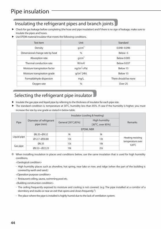
Insulating the refrigerant pipes and branch joints f Check for gas leakage before completing (the hose and pipe insulation) and if there is no sign of leakage, make sure to
insulate the pipes and hoses. f Use EPDM material insulator that meets the following conditions.
Test item Unit Standard
Density g/cm3 0.048~0.096
Dimensional change rate by heat % Below -5
Absorption rate g/cm3 Below 0.005
Thermal conduction rate W/m·K Below 0.037
Moisture transpiration factor ng/(m2·s·Pa) Below 15
Moisture transpiration grade g/(m2·24h) Below 15
Formaldehyde dispersion mg/L There should be none
Oxygen rate % Over 25
Pipe insulation
f Insulate the gas pipe and liquid pipe by referring to the thickness of insulator for each pipe size. f The standard condition is; temperature at 30°C, humidity less than 85%. If case if the humidity is higher, you must
increase the size by one grade as stated in below table.
PipeDiameter of refrigerant
pipe (mm)
Insulator (cooling & heating)
RemarksGeneral [30˚C,85%]High humidity
[30°C, over 85%]
EPDM, NBR
Liquid pipeØ6.35~Ø9.52 9t 9t
Heating resisting temperature over
120°C
Ø12.7~Ø50.80 13t 13t
Gas pipeØ6.35 13t 19t
Ø9.52~ Ø22.23 19t 25t
❇ When installing insulation in places and conditions below, use the same insulation that is used for high humidity conditions.
<Geological condition>
- High humidity places such as shoreline, hot spring, near lake or river, and ridge (when the part of the building is covered by earth and sand.)
<Operation purpose condition>
- Restaurant ceiling, sauna, swimming pool etc.
<Building construction condition>
- The ceiling frequently exposed to moisture and cooling is not covered. (e.g. The pipe installed at a corridor of a dormitory and studio or near an exit that opens and closes frequently.”)
- The place where the pipe is installed is highly humid due to the lack of ventilation system.
Selecting the refrigerant pipe insulator

45
ENGLISH
Caution
• Install the insulation without any gaps or cracks and use adhesive on the connection part of it to prevent moisture from entering.
• Bind the refrigerant pipe with insulation tape if it is exposed to outside sunlight. (When binding the pipe with finishing tape, be careful not to reduce the thickness of the insulation.)
• Install the refrigerant pipe respecting that the insulation does not get thinner on the bent part or hanger of pipe.
• When the thickness of insulation is reduced, reinforce the reduced thickness with additional insulation.
Insulator for refrigerant pipe
a x 3
HangerAdditional Insulator
a
Insulate the refrigerant pipe f Make sure to insulate the refrigerant pipe, branch joint, distribution header, and the connection part of the pipes.
f If you insulate the pipes, condensed water will not fall from the pipes.
f Check if there are any cracks on the insulation at the bent part of the pipe.
Fix securely without any gap.
Install the insulation to be overlapped
Indoor unit
Insulator
Insulator Clamp
Liquid side pipe
Gas side
pipe
Insulator
Insulating pipes Insulating pipes connected behind the EEV kit
• The insulation of the gas and liquid pipes can be in contact with each other but they should not press excessively against each other.
• When the gas side and liquid side pipes are contacting each other, increase the thickness of the insulation by one grade.
• When installing the gas side and liquid side pipes, leave at least 10mm of space.
• When the gas side and liquid side pipes are contacting each other, increase the thickness of the insulation by one grade.
Gas pipe
Liquid pipe
Insulator
Insulator
Gas pipe
10 mm10 mm 10 mm
Liquid pipe

AA
46
Pipe insulation
f Fix the distribution header with a cable tie and cover the connected part.
f Insulate the distribution header and the welded part and wrap the connected part with an adhesive insulation tape to prevent dew formation.
Insulation
Adhesive insulation tape
Insulate the refrigerant pipe
Insulate the distribution header
Insulate after welding a stopper
Adhesive insulation tape
f Fix the distribution header with a hanger after insulating it.
Insulating the branchjoint f Tightly attach the insulator, provided with the branch joint, to the separately purchased insulator. Wrap the connected
part with an insulator (separately purchased item) that has thickness of at least 10mm.
f Use an insulator that resist heat up to 120°C. Wrap the branch joint with an insulation that has thickness of at least 10mm.
Fix securely without any gap.
Provided Insulator
Fix securely without any gap.
Pipe insulator (Separately purchased item)
Pipe insulator (Separately purchased item)
150mmBranch joint
Thickness of the insulator (Separately purchased item) should be thicker than 10mm.
Insulation tape (Separately purchased item)
Pipe insulator (Separately purchased item)
Pipe
❇ Attach the adhesive insulation tape to the pipe, as shown in the picture, after insulating the pipe.
Insulate the distribution header

47
ENGLISH
Insulating the pipe located inside of the outdoor unit f With a pipe insulator, insulate the pipe up to whole service valve located inside of the outdoor unit.
f Seal the gap between the outdoor unit pipe and the insulator. Rainwater and dewdrops may soak through the gap between the pipe and the insulation of the outdoor unit installed on the outside.
f Separate the cover of the pipe and close it after insulation work. Only remove a knock-out hole cover where the pipe will be installed. If the knock-out hole is open unnecessarily, it must be closed. If not, small animals such as squirrels and rats may get into the unit through the hole and the unit may be damaged.

48
AABasic segment display
Step Display content Display
At initial power input Checking segment displaySEG 1 SEG 2 SEG 3 SEG 4
“8” “8” “8” “8”
While setting communication between indoor and outdoor
unit (Addressing)Number of connected indoor units
SEG 1 SEG 2 SEG 3 SEG 4
“A” “d”Number of communicated units
❋ Refer to "View Mode" for communication address
After communication setting
(usual occasion)Transmit/Reception address
SEG 1 SEG 2 SEG 3 SEG 4
I/U: “A” I/U: “0”Reception address
(in decimal number)
❇ I/U : Indoor unit

49
AAENGLISH
Switch Setting Function Remarks
SW51/SW52
Setting total number of installed indoor unit
SW51: Tens digit; SW52:Units digit
Setting can be done from the main outdoor unit onlyEx) When 12 indoor units are installed → SW51: 1, SW52: 2
SW53
K5On —
Not applicableOff —
K6
OnEnable maximum capacity restriction
for cooling operationRestrict excessive capacity increase
when operating indoor units with small capacity
OffDisable maximum capacity restriction
for cooling operation—
K7On —
Not applicableOff —
K8On —
Not applicableOff —
Setting outdoor unit option switch and key function
SW51 SW52
SW53
ON
1 2 3 4
0
38
9 1
6 5 4
2
7
0
38
9 1
6 5 4
2
7
Setting outdoor unit key function

AA
50
K1
K2
K3
K4
Installing and setting the option with tact switch and explanation of the functions
□ Setting the option(1) Press and hold K2 to enter the option setting. (Only available when the operation is stopped)
- If you enter the option setting, display will show the following.
- Seg 1 and Seg 2 will display the number for selected option.
- Seg 3 and Seg 4 will display the number for set value of the selected option.(2) If you have entered option setting, you can shortly press the K1 switch to adjust the value of the Seg 1, Seg 2 and select the desired
option. (Refer to pages 51~52 for the Seg number of the function for each option)
Example)
((3) If you have selected desired option, you can shortly press the K2 switch to adjust the value of the Seg 3, Seg 4 and change the function for the selected option. (Refer to pages 51~52 for the Seg number of the function for each option)
Example)
(4) After selecting the function for options, press and hold the K2 switch for 2 seconds. Edited value of the option will be saved when entire segments blinks and tracking mode begins.
Setting outdoor unit option switch and key function

51
ENGLISH
Optional item Input unit SEG1 SEG2 SEG3 SEG4 Function of the option Remarks
Emergency operation for compressor malfunction
Main 0 0
0 0 Disabled (Factory Default)
0 1 Not applicable
0 2 Not applicable
Cooling capacity
correctionMain 0 1
0 0 7-9 (Factory default)
Targeted evaporation temperature [°C].
(When low temperature value is set, discharged air temperature of the indoor unit will decrease)
0 1 5-7
0 2 9-11
0 3 10-12
0 4 11-13
0 5 12-14
0 6 13-15
Capcity correction for
heatingMain 0 2
0 0 3.0 (Factory default)
Targeted high pressure [MPa].
(When low pressure value is set, discharged air temperature of the indoor unit will decrease)
0 1 2.5
0 2 2.6
0 3 2.7
0 4 2.8
0 5 2.9
0 6 3.1
0 7 3.2
0 8 3.3
Current restriction
rateMain 0 3
0 0 100% (Factory default)
When restriction option is set, cooling and heating performance may decrease.
0 1 95 %
0 2 90 %
0 3 85 %
0 4 80 %
0 5 75 %
0 6 70 %
0 7 65 %
0 8 60 %
0 9 55 %
1 0 50 %
1 1 No restriction
• Edited option will not be saved if you do not end the option setting as explained in above instruction.Caution
❇ While you are setting the option, you may press and hold the K1 button to reset the value to previous setting. ❇ If you want to restore the setting to factory default, press and hold the K4 button while you are in the option setting mode.
- If you press and hold the K4 button, setting will be restored to factory default but it doesn't mean that restored setting is saved. Press and hold the K2 button. When the segments shows that tracking mode is in progress, setting will be saved.

AA
52
Optional item Input unit SEG1 SEG2 SEG3 SEG4 Function of the option Remarks
Oil collection interval
Main 0 40 0 Factory default
0 1 Shorten the interval by 1/2
Temperature to trigger
defrost operation
Main 0 5
0 0 Factory default
0 1
Apply setting when the product is being installed in
humid area such as near river or lake
Fan speed correction for outdoor unit
Main 0 6
0 0 Factory default
0 1 Increase fan speedIncrease the outdoor unit's fan speed to maximum value
Silent mode for night-time
Main 0 7
0 0 Disabled (Factory default)
0 1 LEVEL 1Enable silent mode for night-time
0 2 LEVEL 2
0 3 LEVEL 3
High-head condition
settingMain 0 8
0 0 Disabled (Factory default)
0 1 Not applicable
0 2 Not applicable
0 3 Not applicable
Long-pipng condition
setting(Setting is
unnecessary if high-head
condition is set)
Main 0 9
0 0 Disabled (Factory Default)
0 1 LEVEL 1When equivalent length of farthest indoor unit from the outdoor unit is over 100m
0 2 Not applicable
Energy saving setting
Main 1 0
0 0 Disabled (Factory default)
0 1 Enabled
Energy saving mode triggers when the room temperature reaches desired temperature while operating in heating mode.
Not applicable Main 1 10 0 Not applicable
0 1 Not applicable
Not applicable Main 1 20 0 Not applicable
0 1 Not applicable
Channel address
Main 1 3
A UAutomatic setting (factory default) Address for classifying the
product from upper level controller(DMS,S-NET 3,etc.)0 - 15
Manual setting for channel
0 – 15
Snow accumulation
prevention control
Main 1 4
0 0 Enabled During snow accmulation , the fan may spin even when the unit is not in operation0 1 Disabled (Factory default)
Setting outdoor unit option switch and key function
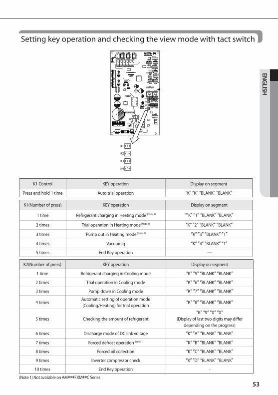
53
ENGLISH
K1(Number of press) KEY operation Display on segment
1 time Refrigerant charging in Heating mode (Note 1) ““K” ”1” “BLANK” “BLANK”
2 times Trial operation in Heating mode (Note 1) “K” ”2” “BLANK” “BLANK”
3 times Pump out in Heating mode (Note 1) “K” ”3” “BLANK” “1”
4 times Vacuumig “K” ”4” “BLANK” “1”
5 times End Key operation —
K2(Number of press) KEY operation Display on segment
1 time Refrigerant charging in Cooling mode “K” ”5” “BLANK” “BLANK”
2 times Trial operation in Cooling mode “K” ”6” “BLANK” “BLANK”
3 times Pump down in Cooling mode “K” ”7” “BLANK” “BLANK”
4 timesAutomatic setting of operation mode (Cooling/Heating) for trial operation
“K” ”8” “BLANK” “BLANK”
5 times Checking the amount of refrigerant“K” “9” “X” “X”
(Display of last two digits may differ depending on the progress)
6 times Discharge mode of DC link voltage “K” ”A” “BLANK” “BLANK”
7 times Forced defrost operation (Note 1) “K” ”B” “BLANK” “BLANK”
8 times Forced oil collection “K” ”C” “BLANK” “BLANK”
9 times Inverter compressor check “K” ”D” “BLANK” “BLANK”
10 times End Key operation -
(Note 1) Not available on AM***FXM**C Series
K1
K2
K3
K4
K1 Control KEY operation Display on segment
Press and hold 1 time Auto trial operation “K” ”K” “BLANK” “BLANK”
Setting key operation and checking the view mode with tact switch

AA
54
K3(Number of press) KEY operation Display on segment
1 time Intialize (Reset) setting Same as initial state
K4 (Press and hold to enter the setting) → K4 press
(Number of press)Displayed content
Display on segment
Page 1 Page 2
0 time Main version MAIN Ver. (ex) 1412)
1 time Inverter version INV1 Ver. (ex) 1412)
2 times EEP version EEP Ver. (ex) 1412)
3 times Assigned address of the units AUTOSEG 1,2 SEG 3,4
Indoor unit: “A" , "0" Address (ex) 07)
4 timesManually assigned address of
the unitsMANU
SEG 1,2 SEG 3,4
Indoor unit: “A" , "0" Address (ex) 15)
❇ Even when the outdoor unit power is off, it is dangerous when you come in contact with inverter PCB since it is charged with high DC voltage.
❇ When replacing/repairing the PCB, cut-off the power and wait until the DC voltage is discharged before replacing/repairing them. (Wait for more than 15 minutes to allow it to discharge naturally.)
❇ When there were error, 'Dicharge mode of DC link voltage' may not have been effective. Especialy if error E464 has been occured, power element might be damaged by fire and therefore, do not use the 'Discharge mode of DC link voltage'.
❇ During "Discharge mode of DC link voltage", voltage of INV will be displayed.
Setting outdoor unit option switch and key function

55
ENGLISH
K4(Number of press)
KEY operationDisplay on segment
SEG 1 SEG2, 3, 4
1 time Outdoor unit model 1 AM080FXM → 0, 0, 8
2 times Order frequency of compressor 2 120 Hz → 1,2,0
3 times High pressure 3 1.52 MPa → 1, 5, 2
4 times Low pressure 4 0.43 MPa → 0, 4, 3
5 times Discharge temperature of compressor 5 87 °C → 0, 8, 7
6 times IPM temperature of compressor 6 87 °C → 0, 8, 7
7 times CT sensor value of compressor 7 2 A → 0, 2, 0
8 times Suction temperature 8 -42 °C → -, 4, 2
9 times COND OUT temperature 9 -42 °C → -, 4, 2
10 times Liquid pipe temperature A -42 °C → -, 4, 2
11 times TOP temperature of compressor B 87 °C → 0, 8, 7
12 times Outdoor temperature C -42 °C → -, 4, 2
13 times EVI inlet temperature D -42 °C → -, 4, 2
14 times EVI outlet temperature E -42 °C → -, 4, 2
15 times Main EEV step F 2000 steps → 2, 0, 0
16 times EVI EEV step G 300 steps → 3, 0, 0
17 times Fan step H 13 steps → 0, 1, 3
18 times Current frequency of compressor I 120 Hz → 1,2,0
19 times Master indoor unit address JMaster indoor unit not seleted → BLANK , N , D
If indoor unit No.1 is seleted as the master unit →0 , 0 , 1

AA
56
1. Before supplying the power, use DC 500 V insulation resistance tester to measure the power (3 phase: R, S, T/ 1 phase: L, N) terminal and the outdoor unit grounding.
- Measurement should be over 30MΩ.
2. Before supplying the power, use a voltmeter and phase tester to check the voltage and the phase.
- R, S, T, N terminal: check if the voltage is within 380-415 V between wires (R-S, S-T, T-R) and 200-240 V between phases (R-N, S-N, T-N) before turning on the switch.
Caution
• Never measure the communication terminal since communication circuit may get damaged.
• Check for short-circuit of the communication terminal with a general circuit tester.
N
T
S
R< ELB >
230V
400V400V
400V
230V 230V
3. Check if the R-410A indoor units are connected.
4. When N phase is not correctly connected to R, S and T phase, over-voltage protection control will be in effect and it will cut-off the power of the PCB. Check the power cable connection of the N phase if the PCB is not turned on.
5. Check the following after the installation is completed.
Things to check after completing the installation

57
ENGLISH
Installation work
Outdoor unit
• Have you checked the external surface and the inside of the outdoor unit?
• Is there any possibility of short-circuit caused by the heat of an outdoor unit?
• Is the place well-ventilated and ensures space for service?
• Is the outdoor unit fixed securely to withstand any external force?
Indoor unit
• Have you checked the external surface and the inside of the indoor unit?
• Is there enough space for service?
• Have you checked if the center of the indoor unit is ensured and it is installed horizontally?
Refrigerant pipe work
• Have you selected correct pipes?
• Are the liquid and gas valve open?
• Is the total number of connected indoor units within the allowable range?
• Are the length and the height difference between the refrigerant pipes within the allowable range?
• Are the branch joints properly installed?
• Did you check the connection of liquid and gas pipes?
• Have you selected correct insulator for pipes and insulated them correctly?
• DId you insulate the pipes and connection part correctly?
• Is the quantity of the additional refrigerant correctly weighed in? (You must record the amount of additional refrigerant on the service record paper placed inside of the outdoor unit.)
Drain pipe work
• Have you checked if the drain pipes of the indoor and outdoor unit are connected together?
• Have you completed the drain test?
• Is the drain pipe properly insulated?
Electrical wiring work
• Are the power cable and communication cable tightened firmly on the terminal board within the range of rated tightening torque?
• Have you checked for cross-connection of the power and communication cables?
• Have you performed the earthing work 3 to the outdoor unit?
• Did you make sure to use 2-core cable (not multi-core cable) for the communication cable?
• Is the length of the wire within allowed range?
• Is the wiring route correct?
Setting address• Did you set the address of the indoor and outdoor units properly?
• Did you set the address of the indoor and outdoor units properly? (When using multiple remote controllers)
Option• If there is a possibility of the outdoor unit from vibrating, check whether the anti-vibration
frame is correctly installed.

AA
58
Inspection & test operation
Caution
Precautions before test operation
• When the outdoor temperature is low, turn on the main power 6 hours before beginning the operation.
- If you start the operation immediately after turning on the main power, it may cause serious damage to the part within the product.
• Do not touch the refrigerant pipe during or right after the operation.
- Refrigerant pipe may be hot or cold during or right after the operation depending on the status of the refrigerant which flows through the refrigerant pipe, compressor and other parts of the refrigerant cycle.
• Do not operate the product with its panel or protection nets off.
- There is risk of personal injury from the parts that rotates, heated or with the high voltage.
• Do not turn off the main power immediately after stopping the operation.
- Wait for at least 5 minutes before turning off the main power. If not, water leakage or other problems may occur.
1. Check the power cable and communication cable of the indoor and outdoor unit.
2. Supply power to the outdoor unit 6 hours before trial operation to pre-heat the crank case heater.
3. Before supplying the power, use a voltmeter and phase tester to check the voltage and the phase.
- R, S, T, N terminal: check if the voltage is within 380 -415 V between wires (R-S, S-T, T-R) and 200-240 V between phases (R-N, S-N, T-N).
4. When the power is supplied, outdoor unit will execute tracking to check the indoor unit connection and other optional functions.
5. Write down the installation report on the service history report paper attached on the front part of the control box.
Caution• Supply power to the outdoor unit 6 hours before auto trial operation to pre-heat the crank case heater.
6. Guaranteed range of auto trial operation
For precise judgment, you must perform auto trial operation in below indoor/outdoor temperature condition.
50
40
30
20
10
0
-10
-205 10 15 20 25 30 35 40 45
Indoor temperature (°C)
CoolingHeating
Out
door
tem
pera
ture
(°C)
- In Auto trial operation, product will automatically select either cooling or heating mode and operate in selected mode.
- AM***FXM**C (Cooling Only) models operate only cooling mode in Auto trial operation. (Cooling only models don't operate Auto trial operation in case of outdoor temperature below -5°C or indoor temperature below 5°C)
- In the temperature range marked with slashed pattern, system protection control may trigger during operation.(If the system protection control is enabled, it can be hard to get the precise judgment after the auto trial operation.)
- When the temperature is outside of guaranteed range, accuracy of judgment on auto trial operation may decrease near boarder line area.
Checklist before auto trial operation

59
ENGLISH
1. If the Auto Trial Operation is not completed, normal operation will be prohibited.
- When the auto trial operation is not completed, UP (UnPrepared) will appear on the segment after the communication check and restrict compressor from operating. (UP Mode will be cleared automatically when auto trial mode is completed.)
- Auto trial operation may take 20 minutes to maximum 2 hours depending on the operation status.
- During auto trial operation, noise can be generated due to vavle inspection. (Check the product if abnormal noise occurs continously)
2. When error occurs during auto trial operation, check the error code and take appropriate measures.
- Refer to next page when E503 error occurs.
- Refer to service manual if you need inspection or when other errors occur.
3. When auto trial operation ends, use S-NET pro or S-CHECKER to issue a result report.
- Refer to service manual for further actions if you have any items with "inspection required" sign on the result report.
- After taking appropriate measure for the items with "inpection required" sign, run the auto trial operation again.
4. Check the following items by running trial operation (cooling/heating).
- Check if cooling/heating operation performs normally.
- Individual indoor unit control: Check for air flow direction and fan speed.
- Check for abnormal operation noise from the indoor and outdoor unit.
- Check for proper draining from the indoor unit during cooling operation.
- Use S-NET pro to check the detail operation status.
5. Explain to the user how to use the air conditioner according to the user's manual.
6. Hand over the installation manual to the customer so they can keep it with them.
Auto trial operation
Caution
• Make sure to close the outdoor unit cabinet during operation. If you operate the unit with the front cabinet open, it may cause damage to the product.

60
AA
Measure to take when E503 error occurs
Inspection & trial operation
❇ Symptoms for abnormal operation of the 4way valve
- Refrigerant noise is increased while compressor operatres and suction temperature remains over 20°C compared to low pressure's saturation temperature.
- Temperature of Eva. in/out remains below 0 °C during heating operation.
❇ Symptoms for abnormal operation of the Main EEV
- Error on controlling degree of superheat of compressor inlet during heating operation.
: If there's operation error while the EEV is fully opened, suction superheat cannot be secured (below 0 °C) and discharge temperature of the compressor will be low. (DSH is below 10°C)
: If there's operation error while the EEV is fully closed, low pressure will decrease and suction superheat will increase excessively.
1. Run trial operation mode for more than 30 minutes
2. Run Fan mode for more than 10 minutes
3. Restart the auto trial operation
Yes
Yes
Yes
Open the service valve of the outdoor unitNo.
Is the service valve of the outdoor unit opened?
Check the 4way valve and Main EEVNo.
Is 4way valve and main EEV operating normally?
Check for leakage. Perform vacuuming and charge refrigerant
No.Is the quantity of the refrigerant
appropriate?
• If the service valve need to be detected, auto detection mode will end. Check both gas pipe and liquid pipe service valves when detecting service valve.
• When 4way valve, Main EEV detection is needed, run heating trial operation for more than 1 hour and analyze the data to check for a problem.
• If there's frost formed in outdoor unit or the outdoor unit is operating in deforst operation, it may be hard to detect problem normally. In this case, run heating trial operation for more than 1 hour.
• If the opreation range is not within guaranteed range, error may occur even though the product is normal.
Caution

61
AAENGLISH
Automatic refrigerant amount detection functionThis function detects amount of refrigerant in the system through refrigerant amount detection operation.
Start
Press the Tact switch "K2" 5 times
Check the amount of refrigerant
Judge the amount of refrigerant
Judgment on the amount of refrigerant: Normal / Excessive /
Insufficient
Judgment not available
Judgment not available
Connect S-Net Pro Judge the amount of refrigerant
Judgment on the amount of refrigerant: Normal / Excessive /
Insufficient
Satisfy the temperature condition Satisfy the temperature condition
Check the amount of refrigerant
Input S-CHECKER signal
Check stability Check stability
End
Yes
No No
Yes

62
AA
Caution
• If the temperature is out of the guaranteed range below, exact result will not be obtained.
- Indoor: 20~32 °C
- Outdoor: 5~43 °C
• If the operation cycle is not stable, the operation of refrigerant amount check may be forcibly finished.
• Accuracy of the result may decrease if the product has not been operated for a long period of time or heat mode has been operated before running the function of refrigerant amount check. Therefore, use the function of refrigerant amount check after operating the product in cool mode for at least 30 minutes.
• Product may trigger system protection operation depending on the installation environment. In this case, the result of refrigerant amount check may not be accurate.
Actions to take for the check result
• Excessive amount of refrigerant
- Discharge 5% of total amount of refrigerant and restart the refrigerant amount check.
• Insufficient amount of refrigerant
- Add 5% of the total amount of refrigerant and restart the refrigerant amount check.
• Insufficient degree of supercooling
- Add 10 % of the total amount of refrigerant and restart the refrigerant amount check.
• Judgment not available
- Check if the function of refrigerant amount check is executed within the guaranteed temperature range. Run trial operation to check if there are other problems on the system.
Automatic refrigerant amount detection function

63
AAENGLISH
Remarks

"EEE Yönetmeliğine Uygundur" "This EEE is compliant with RoHS"

This manual is made with 100% recycled paper.
DVM S ECO:
AM✴✴✴FXMDG Series
imagine the possibilitiesThank you for purchasing this Samsung product. To receive more complete service, please register your product atwww.samsung.com
Air ConditionerInstallation manual
DB68-04412A-1EN ES FR IT PT DE EL NL PL HU RU