aae 451 aircraft design details on deliverable itemsandrisan/courses/aae451_f2008/... · aae 451...
TRANSCRIPT
1
AAE 451 Aircraft Design Details on Deliverable Items
Individual Design Journal (everyone must keep one)
Purpose: This design journal will record the evolution of your work on your team's aircraft design. Format: Any new notebook with the following features is acceptable:
• permanently bound with durable cover; • numbered pages with tear-out copy pages; and
• 0.20 or 0.25 inch grid on all pages.
(University Bookstore has best selection: Carbonless Tear-Out Copies: National 43-644, National 43-641, or Jones & Baillet ISBN 0-86720-876-7. Carbon Copy: National 43-645.) General Guidelines 1. Your Design Journal is primarily a record of what you have done on this design. 2. Include any entry for each work session which includes the following:
• The date.
• A brief statement of your objective for that session.
• A record of what was done.
• Each entry should be terminated by your dated signature. If there is any reason to believe that your work will be legally important (e.g., a patent application), you should have a colleague read your entry and write “read and understood by” and then sign and date the entry.
3. A typical entry in your Design Journal will be ½ to 1 page. Some sessions will require more detail. In addition to text, show sketches and graphs.
4. Think of how information in your Design Journal could be used in the future.
2
• By yourself to refer back to when working on the design and when writing an overall project report.
• By a colleague who is continuing your design after you have left the company.
• By the company legal department when a patent application is filed. Specific Guidelines 1. You are to record all of your assumptions, explanations, rational for decisions, your
decision making process, analyses, computations, etc. 2. Do not erase or remove anything. Things that are wrong or out of date should be
crossed through once so that they are still legible. Often the method of perhaps even old results will become meaningful again later. A brief explanation why material is crossed out is often helpful later when you are reviewing or modifying your results.
3. Major computer generated results can be stapled into the journal. 4. Your entries should be
A. dated, B. neatly written, C. cross referenced throughout so that it is obvious where input numbers come
from. D. All pages should be consecutively numbered.
5. Your entries should include A. carefully stated and identified assumptions, B. no more significant figures in your calculations then are justified by the
accuracy of the method used. In preliminary design it is generally not justified to carry more then three significant figures.
6. You will be asked to hand in your Design Journal at several points during the semester. It will form a portion of your course grade.
7. The Design Journal is not something done as the last minute. It should be thought of as a workbook for storing and organizing all your work as the work is performed.
8. The basic method of organization in the Design Journal is the serial nature of journal. Your design reports will allow you to summarize and reorganize your final results. So don't worry if the organization within your design journal is not the best. You may find it is helpful to periodically summarize your work in carefully labeled summary pages.
9. If you use the Design Journal as it should be, you will always be able to locate every decision and computation made in your design.
10. Don't loose your Design Journal.
3
Individual Deliverable Items: (every student must submit one)
1. Individual Mission Evaluation - A written discussion of the “mission” highlighting
critical issues and areas of concern. This should be 1-3 pages in length and attempt to identify each “phase” of the mission as outlined in the Mission Specification and quantify as many requirements as possible as posed by the Mission Specification.
2. Individual System Concept - Each class member will develop their own concept
vehicle for this mission, this concept must include a detailed “hand” (not computer) sketch of a three view external drawing, internal equipment layout with approximate scale. This should also include a two page written concept description highlighting strengths and potential problems with the proposed concept. Key technical requirements must be identified.
3. Two individual trade studies (see below).

4
Team Deliverable Items: (each team submits one)
➽ Teams must insure that all team members have equal opportunity to speak throughout
the semester. Group leaders are not to be the mouthpiece of their team. By the end of the semester each team member must have spoken roughly the same number of times and for roughly the same number of minutes.
1. Weekly Team Time Tracking Summary - details individual time
resource allocation for work conducted in this class up to and including Sunday night. This includes in-class time and out-of-class time. This information will then be due every Tuesday for the remainder of the semester. Each group will develop their own data requirements, collection procedure and reporting format.
2. Team Design Requirements and Objectives (DR&O) - Formal written
report [3-5 pages]. This is a very critical document since the team’s accomplishments will be evaluated against their quantitative objectives (see additional description below).
3. Team Candidate Concepts Defined - Three view sketches to scale for presentation in class along with brief written discussion of unique aspects of the concepts. Three concepts or perhaps variations on a single concept are desired.
4. Flight Control System Written Status Report (D&C students from each team make one joint report (See description below)
5. Concept Selection Document and Presentation (See description below.)
6. Project Plan Review - describes planned engineering activities for the remainder of this project.
7. PDRs, QDRs, and CDR, ets.
Team Design Requirements and Objectives (DR&O) Document The Design Requirements and Objectives (DR&O) document is a formal written report [3-5 pages] containing several things. First, it should describe your vision of what the aircraft will do when it is completed. It is not a progress report on the status of your design. It provides the big picture view of your completed design. If your team chooses to focus on something different or unusual in the design (as compared to what we have been talking about in class) you need to put it in the DR&O. This document is your statement of what the vehicle is to do, i.e., the design objectives. You will be judged (graded) on how well your design achieved your stated objectives in the DR&O.

5
Second, the document lists all design requirements that more quantitatively describe your vehicle. For example, the vehicle is required to have a certain endurance. You may want to impose a requirement that is different then what we have already talked about in class. For example, you may want to specify a particular minimum speed. Together the design requirements serve to quantitatively describe what the final design will do and serve to narrow down the size of the design space. The design requirements may define a portion of the design space known to be unique so as to offer greater market potential or cost advantages. In summary, this document describes what it is you are trying to design. It is a very important document. Without a clear view of what you are trying to accomplish you are doomed to wander and produce a design that is unlikely to succeed. If you suggest something in the DR&O that I don't approve of I may ask you to make modifications.
Team Candidate Concepts Defined
Three view sketches to scale for presentation in class along with brief written discussion of unique aspects of the concepts. Three concepts or perhaps variations on a single concept are desired.
Team Concept Selection Document and Presentation (4 presentations, 8 minutes long)
This one document describes the aircraft concept for your team. It must include a detailed “hand” (not computer) sketch of a three view external drawing including internal equipment layout drawn with approximate scale. Dimensions must be included on the sketch. Please also provide a table of physical properties of your vehicle as best you know them at this time. Also included should be a two page written concept description highlighting strengths and potential problems with the proposed concept. Key technical requirements must be identified. Presentation: Your team will make an integrated in-class presentation.

6
Flight Control System Written Status Report This is a single report prepared by D&C students from all teams. The objectives are to inventory all the flight control hardware we have at the Aerospace Sciences Lab. This includes
• Finding all radio control transmitter and receivers. There should be at lease 3 sets. We need 5 sets and may have to order 2 more.
• Finding and inventorying all flight control related hardware including servos, wiring pushrods, battery chargers, etc. (Some equipment may be installed in previous aircraft). Students will be forming a Purdue Aeromodelers Club and they will also be using this equipment as well as previously designed AAE451 aircraft.
• Obtaining up-to-date catalogs from Tower Hobbies. • Preparing a brief report on the status of the 3-5 shipsets of flight control related
hardware.
Vehicle Sizing Preliminary Design Review (4 presentations, 20 minutes long)
Using PowerPoint slides please provide the following design material. Preliminary Weight Estimate:
1. Describe your method of weight estimation (e.g., the method of Roskam, Raymer, or other method).
2. Describe your data base of historical weight data and how it was compiled.
Preliminary Wing Loading and Power Loading Estimate: 1. Provide a constraint diagram with regions of feasible design space clearly
denoted, 2. Show the equations for each constraint, 3. Discuss of each constraint with explanations of how each number was
determined using sound engineering judgment.
Summarize your aircraft size: weight estimate, wing area estimate, motor horsepower estimate.
Indicate who on your team were the major contributors to this effort.
7
Project Plan Review (PPR) (4 presentations, 8 minutes long)
Each team will make a 8 minute formal presentation describing their planned engineering
activities for the remainder of this project. It should include scheduling, task assignments, and milestones. Include major team
meetings. Include any planned tests or major pieces of work you intend to complete before the
Critical Design Review (CDR). Each team member must agree to the team meeting dates. It may not be possible for each team member to participate in this presentation. However,
make sure that you spread the speaking opportunities around your team.
Propulsion 1 PDR (4 presentations, 20 minutes long)
Each team makes a 20-minute PowerPoint presentation of the propulsion system of their design. This will leave 10 minutes for questions. You may not have all the data requested below for the first Propulsion PDR. Describe the geometric properties of your propeller (diameter, pitch thickness, airfoil section, twist distribution, chord distribution, shape (under cambered?), etc.). Is your propeller twist data theoretically calculated or experimentally measured? Describe the aerodynamic properties of your propeller (thrust and power coefficient as a function of advance ratio (J=V/nD)). Present plots of CT, CP and η as a function of J. Program gold.m can give this to you. Describe the gearbox you intend to use (efficiency, gear ratio) and the speed controller. Describe your electric motor you intend to use (rated horsepower, motor efficiency, motor constants, rated voltage, rated number of cells, manufacturer (if available)). Describe your procedure for selecting this propeller, gearbox and motor. Determine if the mission requirements can be met with the battery you intend to carry. This will require you to redo the mission analysis we did early in the semester using updated engine, drag, and flight condition information. Turn in paper copies of all transparencies.
8
Structures and Weights 1 QDR Geometric layout of your wing structure
geometry of wing spar(s) location of wing ribs (if any) location of wing stringers (if any) wing coverings (if any) materials of wing components
Material properties of all structural materials (balsa, spruce, plywood, foam, etc.) Analysis of wing loads
• What are the maximum bending and torsional loading conditions? • What are the properties (area, skin thickness, width, height) of the wing box (assumed uniform with span?) to insure that the wing tip rotates by less than 1 degree? • Load distribution at maximum wing loading. • Maximum wing root bending moment. • What are the properties (area, skin thickness, width, height) of the wing box (assumed uniform with span?) to insure that the wing box can handle the maximum bending loads? • Based on these two analyses, what are the final properties (area, skin thickness, width, height) of the wing box (assumed uniform with span?). • Clearly state any simplifying assumptions you make.
Landing Gear Location, configuration, special structure, and load analysis Longitudinal tip-over analysis Lateral tip-over analysis Tail-strike analysis
Weight Estimate center of gravity moments and products of inertia
Aerodynamics 1 PDR (4 presentations, 20 minutes long)
Aircraft Geometry Airfoil section for wing, vertical and horizontal tails. Wing and tail geometry including sweep angle, taper ratio, dihedral angle. Aircraft wetted area, Aspect ratio of wing 3-view drawing drawn to scale and dimensioned.
9
Aerodynamic mathematical model Please provide numerical values of all the coefficients listed below. Take account of three-dimensional effects and be sure to include the effects of the horizontal tail. Lift Coefficient CL=CLo + CLα*α +(CLδe*δe (optional)) Drag Polar CD=CDo+k*CL*CL Maximum Lift Coefficient CLmax (Add any other information listed under Aerodynamics 2 QDR that you can get to)
Individual Trade Study #1 Each student will hand in a trade study. A trade study is a scientific analysis that allows us to make an informed decision about picking a value of some design variable. The design variable is important for some reason. You must understand why the design variable is important, i.e. what impact the design variable has on the performance properties of your design. You need to be able to mathematically relate the design variable to the performance property(ies) that make the design variable important. You also need some criterion that tells you when you have enough of the performance property. The process is outlined below: Given: A criterion on the performance property. Find: The relationship between the design variable and the performance property. Plot that relationship. You may want to generate a family of curves if there are secondary design variables that influence this plot. Decision rule: Adjust the design variable until the criterion is met. You may also explore whether there are other important things to learn from your relationship between your performance property and your design variable. Perhaps secondary design variables have an important influence on your decision.
Example:

10
Criterion: Static margin must be greater then .15 Find: The relationship between design variable horizontal tail area (Sh) and static margin is given by Roskam (421 book) equations 4.42 and 3.38. Plot the relationship between performance property (static margin) and design variable (Sh). Make reasonable assumptions on secondary design variables (e.g., dε/dα) Decision rule: Select horizontal tail area (Sh) that gives the desired static margin. For reasonable values of tail area, where must your c.g. be? Do you think you will have any problems getting your c.g. to be that far forward. What is the impact of the dynamic pressure ratio ηh on your decision?
Other Examples
For tail sizing trade studies, please look up X-plots in Roskam's Airplane Design Series Volume II. There is a longitudinal X-plot for sizing the horizontal tail and a directional X-plot for sizing the vertical tail. The aircraft trim diagram (see Roskam 421 book) can be used to formulate a trade study to size the elevator or elevator deflection limits. Trade studies exist for every aspect of aircraft design. Trade Study #1 1. Brief statement of purpose of study. 2. Detailed list of design variables - those parameters which you can control. List ay
constraints on the design variables. 3. Measures of merit - those parameters which you will use to evaluate the design. 4. Description of the tools used with particular emphasis on the assumptions associated
with them and their limitations. 5. Presentation of results of the study - graphical are preferred but tables or charts are
acceptable if they most adequately represent the results. 6. Discussion of the results of the study. 7. Brief discussion of the impact of they study on the design. The basic format for the presentation of the trade study is up to each engineer. A tech memo format might be ideal. The report should not exceed 8 pages which includes all background, discussion and results. If a trade study involves hardware development, the engineer should discuss with management an appropriate format for presenting their results.
11
Dynamics and Control 1 QDR (Flight Control)
(4 presentations, 8 minutes long) Determine the mathematical model for the hovering flight condition Find the applicable transfer function that relates output to input (e.g. roll angular rate to aileron deflection transfer function). Find the root locus for feeding back that output to that input. Select a nominal gain to achieve the desired dynamics. If you cannot achieve the desired dynamics with a gain alone add a compensator and repeat the design process with compensator in the loop.
Structures and Weights 2 PDR (4 presentations, 20 minutes long)
Landing Gear
• Design strategy (e.g., design to never break, design to break gently) • Analysis of impulsive loads • Location, configuration, special structure, and load analysis • Longitudinal tip-over analysis • Lateral tip-over analysis • Tail-strike analysis
Weight Determination
• center of gravity • moments and products of inertia • complete tabular listing of all parts, location, weight
Geometric layout of your wing structure
• geometry of wing spar(s) • location of wing ribs (if any) • location of wing stringers (if any) • wing coverings (if any) • materials of wing components
Analysis of wing loads • V-n diagram (see Raymer pages 331-343) • What are the maximum bending and torsional loading conditions? • What are the properties (area, skin thickness, width, height) of the wing box
(assumed uniform with span?) to insure that the wing tip rotates by less than 1 degree?

12
• Load distribution at maximum wing loading. • Maximum wing root bending moment. • What are the properties (area, skin thickness, width, height) of the wing box
(assumed uniform with span?) to insure that the wing box can handle the maximum bending loads?
• Based on these two analyses, what are the final properties (area, skin thickness, width, height) of the wing box (assumed uniform with span?).
• Clearly state any simplifying assumptions you make. • Loading condition for which the wing will fail. • Maximum wing tip vertical deflections.
Fuselage and Tail Structure • Analysis of the wing-fuselage attachment (e.g., how many rubber bands?). • Geometric layout of your fuselage structure. • Geometric layout of your horizontal tail structure. • Geometric layout of your vertical tail structure.
Propulsion 2 QDR You may not be able to complete all of this. Do what you can and we will revisit this material in the next Propulsion review.
Propulsion Summary • Summarize the geometric properties of your propeller (diameter, pitch thickness,
airfoil section, twist distribution, chord distribution, shape (under-cambered?), etc.). Is your propeller twist data theoretically calculated or experimentally measured?
• Summarize the aerodynamic properties of your propeller (thrust and power
coefficient as a function of advance ratio (J=V/nD)). Present plots of CT, CP and η as a function of J. Program gold.m can give this to you.
• Summarize the engine you intend to use (rated horsepower @rpm, fuel injection
(?), fuel feed system, cost, reliability, etc.) Propulsion Design Procedure
• Describe your procedure for selecting this propeller, and engine. What sized the engine and propeller? Why did you select the engine/propeller combination? How did you match the engine/propeller to the aircraft?
• What is your expected endurance? How did you compute this?
• Justify the reasonableness of your design procedure for matching the engine to
the propeller to the airframe.

13
Aerodynamics 2 QDR Aircraft Geometry Airfoil section for wing, vertical and horizontal tails. Wing and tail geometry including sweep angle, taper ratio, dihedral angle. Aircraft wetted area, Aspect ratio of wing 3-view drawing drawn to scale and dimensioned.
Aerodynamic mathematical model (highlight any significant revisions since the previous Aerodynamics review) Please provide numerical values of all the coefficients listed below. Take account of three-dimensional effects and be sure to include the effects of the horizontal tail. Document your source for determining the three-dimensional effects. Lift Coefficient CL=CLo + CLα*α +(CLδe*δe) Pitching Moment Coefficient about the quarter chord point CM=CMo + CMα*α +(CMδe*δe)
Aircraft Trim Diagram (see Roskam AAE421 book pages 205-216 Note Aerodynamics people should be preparing all “Basic Constants” required as inputs to the MATLAB code that computes all stability and control derivatives and equations of motion (FlatEarth.m). These stability and control derivatives will be required by the dynamics and control group. Trimability Considerations (Important! If you don’t complete this, include it in the Dynamics and Control PDR) • Construct an Aircraft Trim Diagram (Roskam, Vol VII, p. 12, or Vol VI, . 344) • Do you have enough nose up elevator to fly in steady flight at the stall speed? • Do you have enough nose down elevator to fly in steady flight at the maximum speed
of your aircraft? • Answer these questions for the least favorable c.g. locations. The trim considerations mentioned above help size control surfaces for trimming, i.e., balancing moments. However, do you have enough control power available to maneuver your aircraft?

14
Stability Considerations (optional, but you will need these for the Dynamics and Control PDR)
• range of center of gravity locations for your design; • X-plot (see Roskam, Volume II, Chapter 11) • aerodynamic center location (stick fixed neutral point) (be sure to
include the effects of downwash of large forward surfaces of smaller aft surfaces);
• range static margin; • desired static margin with justification; • volume of horizontal tail with reason for selecting this tail volume; • volume of vertical tail with reason for selecting this tail volume. • dihedral angle and the reason for selecting this amount of dihedral
The Design Issue: Is the vehicle stable in all axes? To check dynamic stability requires full equations of motion (including many aerodynamic stability and control derivatives) and getting them is a lot of work. A simpler procedure is to insure that the static stability criteria are met in each axis. Static Stability
Longitudinal Static Stability (Cmα) achieved by making sure you have sufficient
volume ratio of the horizontal tail (a Class I method of sizing the empennage as described in Roskam Airplane Design, Part II, Chapter 8). See historical examples of aircraft built by previous classes at Purdue.
You need also check to insure that you have sufficient static margin (Xac-Xcg)/c using a longitudinal X-plot. See Roskam Airplane Design, Part II, Chapter 11. The thesis of Mark Peters ("Development of a Light Unmanned Aircraft for the Determination of Flying Qualities Requirements," May 1996) suggests that you need a static margin of at least 15%.
Lateral-Directional Static Stability
Weathercock Stability (Cnβ) achieved by making sure that your design
has sufficient volume ratio of the vertical tail. It is useful to check the volume ratio of the horizontal tail (a Class I method of sizing the empennage as described in Roskam Airplane Design, Part II, Chapter 8). You need also check to insure that you have sufficient static directional stability using a directional X-plot. See Roskam Airplane Design, Part II, Chapter 11.
Dihedral Effect (Clβ) achieved using wing geometric dihedral angle. See
the paper handed out in class ("Wing and Tail Dihedral for
15
Models," by William F. McCombs, Model Aviation, 12/94). Note that amount of wing geometric dihedral angle you need is also influenced by whether you are turning with aileron or turning with rudder alone (requires more wing geometric dihedral angle).
Controllability Considerations (optional, but you will need these for the Flight Performance, Stability & Control PDR)
• size of the elevator with the reason for selecting this control surface size; • size of the rudder with the reason for selecting this control surface size; • size of the aileron (if any) with the reason for selecting this control surface
size; • discussion of why or why not you have included ailerons.
The Design Issue: Sufficient control power (control surface size and deflection limits) must be provided to trim the aircraft (i.e., balancing forces and moments) at all desired flight conditions and to maneuver the aircraft about the trim condition. Pitch, elevator size, Cmδe
It is useful to size the elevator using historical data (a Class I method of sizing the elevator as described in Roskam Airplane Design, Part II, Chapter 8). See also historical examples of aircraft built by previous classes at Purdue. You will need to construct an airplane trim diagram to insure that you have enough elevator to trim at all desired angles of attack (see Roskam Airplane Design Part VI, Chapter 8, Section 3, or see Roskam Airplane Flight Dynamics and Automatic Flight Controls (the AAE-421 book)).
Yaw and/or roll, rudder size, Cnδr It is useful to size the rudder using historical data (a Class I method of sizing the elevator as described in Roskam Airplane Design, Part II, Chapter 8). See also historical examples of aircraft built by previous classes at Purdue. If you plan to use the rudder for turning you will need to also consider how much wing geometric dihedral you need.
Roll, aileron size, Clδa (optional)
It is useful to size the aileron using historical data (a Class I method of sizing the elevator as described in Roskam Airplane Design, Part II, Chapter 8). See also historical examples of aircraft built by previous classes at Purdue. If you intend to roll with rudder alone, you may not need ailerons at all.

16
Individual Trade Study #2 (See description under Individual Trade Study #1)
Two or three PowerPoint slides which are capable of describing the purpose and results of a specific trade study. You will present this study to the class using these viewgraphs and be given 5 minutes to overview the key aspects of your study and its results. Examples of a trade studies. Comparison of lift distributions for different taper ratio to help in selecting the taper ratio that provides the nearest approximation to an elliptical lift distribution. Fuel consumption in cruise and static thrust at takeoff as metrics to select from a family of propellers (pitch and diameters). The effect of propeller pitch-to-diameter ratio on prop and engine RPM, gear ratio, propulsion system sizing, and battery size.
Dynamics and Control 2 PDR Stability and Control • Class 1 sizing (tail volume method) of horizontal and vertical tails • Class 1 sizing (historical data) of control surfaces (elevator, ailerons, rudder) • surface deflection limits • Location of aerodynamic center of aircraft and tails • Location of aircraft c.g. • Determination of desired static margin • Class 2 sizing of the horizontal and vertical tail using X-plots (see Roskam Design or 421
book) • Determination of dihedral angle (see article by McKombs in D&C Sourcebook)
Desirable but not required
• Short period mode damping ratio and natural frequency • Phugoid mode damping ratio and natural frequency • Dutch roll mode damping ratio and natural frequency • Roll mode time constant • Spiral mode time constant • Determination of desired values for the above mentioned modal parameters • Dymamic simulation of vehicle flight mechanics
17
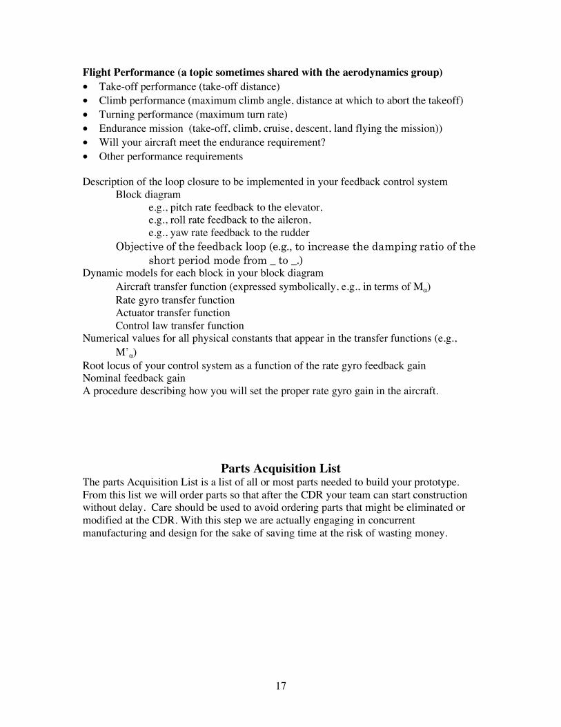
Flight Performance (a topic sometimes shared with the aerodynamics group) • Take-off performance (take-off distance) • Climb performance (maximum climb angle, distance at which to abort the takeoff) • Turning performance (maximum turn rate) • Endurance mission (take-off, climb, cruise, descent, land flying the mission)) • Will your aircraft meet the endurance requirement? • Other performance requirements Description of the loop closure to be implemented in your feedback control system
Block diagram e.g., pitch rate feedback to the elevator, e.g., roll rate feedback to the aileron, e.g., yaw rate feedback to the rudder
Objective of the feedback loop (e.g., to increase the damping ratio of the short period mode from _ to _.)
Dynamic models for each block in your block diagram Aircraft transfer function (expressed symbolically, e.g., in terms of Mα) Rate gyro transfer function Actuator transfer function Control law transfer function
Numerical values for all physical constants that appear in the transfer functions (e.g., M’α)
Root locus of your control system as a function of the rate gyro feedback gain Nominal feedback gain A procedure describing how you will set the proper rate gyro gain in the aircraft.
Parts Acquisition List The parts Acquisition List is a list of all or most parts needed to build your prototype. From this list we will order parts so that after the CDR your team can start construction without delay. Care should be used to avoid ordering parts that might be eliminated or modified at the CDR. With this step we are actually engaging in concurrent manufacturing and design for the sake of saving time at the risk of wasting money.

18
Prototype Fabrication, Economic, and Test Plan Overall Schedule
Compile a list of all tasks to be accomplished by first flight. Schedule tasks to insure all tasks are completed on time. Tasks include parts ordering, the CDR, component testing, prototype fabrication and flight testing. Economic Plan
Estimate costs to complete all component testing, prototype fabrication and testing. Estimate person-hours devoted to your design from start of the semester until the end of the course. Bring time cards up to date and summarize them. Be sure your projected costs are within budget. Flight Test Plan
Develop a strategy for safely test flying your airplane (prior to official first flight) so that on the day of the official first flight your aircraft will successfully perform the mission. The strategy includes a schedule of flight testing, location of the flight test (e.g., outside, inside) and the objectives for each flight test (e.g., unpowered glide, straight line flight, turning flight). Remember you may not fly your aircraft before the Flight Readiness Review.
Critical Design Review (CDR) This 50 minute, formal oral presentation will take place during the lab period and may be videotaped for review and evaluation. Expect at least 10 minutes of questions during your 50-minute presentation. The design is “frozen” at this point and all further efforts are associated with validating the design through prototype fabrication and test. All team members are expected to participate in the oral presentations during the CDR. There will be outside visitors and the presentation is open to the general public. Presentation Outline • 3-view • Tabular summary of the physical properties of your design (including physical units) • Review of each discipline (Remember some members of the audience will not have seen any of your previous presentations. So make this a complete review. Use the PDR as a guide to what to include. You may add material beyond the PDR but you should have no more then 25-30 transparencies for a 50-minute presentation.)
• aerodynamics • dynamics and control including discussion of the feedback control system • structures and landing gear • propulsion
• Prediction of vehicle performance • Unique aspects as of your design • Remaining design problems • Your plan to resolve the problems in a timely manner • Conclusion:s Are you ready to build and fly an aircraft? If not, what are you going to do about it? Written Deliverables One paper copy of your PowerPoint slides for Professor Andrisani and all faculty guests who attend the CDR.

19
Thiokol Final Design Report This major report must contain all required changes from the draft submission as well as complete documentation of the prototype fabrication and testing as described above. It should be considered as one of your first professional publications and treated as such. Each team will submit a single, unbound copy of the report and all attachments. This report is limited to 25 pages (maximum) with unlimited appendices and attachments. Further details concerning this report may be given in class. . In the table of contents of your Thiokol Final Design Report please indicate the primary author(s) of each section (or chapter) and any secondary authors of each section (or chapter) if applicable. The Thiokol Final Design Report will be sent to the Thiokol Corporation for external review and competitive evaluation by a multidisciplinary team of reviewers. Each report will be reviewed by the Thiokol Affiliate Technical Manager, a Thiokol technical writer, and a Thiokol design engineer. The Thiokol design competition stresses excellence in technical writing. The emphasis is on technical content, and effective communication of technical concepts and details. The team that submits the best Thiokol Design Report will be awarded a $75 prize per team member. In addition each team member of the winning team will get his or her name added to the plaque hanging in the Thiokol Corporation display on the third floor of Grissom Hall. The plaque in entitled the Thiokol Semi-annual Purdue Academic Communication Excellence (S.P.A.C.E.) Award for Excellence in Technical Communication. See additional information below.
20
Flight Readiness Review In this review the completed aircraft checked by the “professional pilot” for flight safety and flight worthiness. It must be a complete aircraft with servos and electronics installed and with operational control surfaces and landing gear.
Lessons Learned and Vehicle Summary Presentation (informal presentation, 20 minutes followed by a 10 minute question and answer
period). This presentation includes the results of flight testing and describes any final design modifications you may have made. It provides a complete description of the vehicle as it was actually built. It discusses why the built vehicle was different then the vehicle described in the CDR.
Final Report Addendum: Lessons Learned and Vehicle Summary
This report includes the results of flight testing and describes any final design modifications you may have made. It provides a complete description of the vehicle as it was actually built. It discusses why the built vehicle was different then the vehicle described in the CDR. There must be a table data describing of all geometric, mass, propulsion, and aerodynamic constants. Also include a listing of the BasicConstants m-file that describes your aircraft. e-mail to Professor Andrisani your updated BasicConstants file.
21
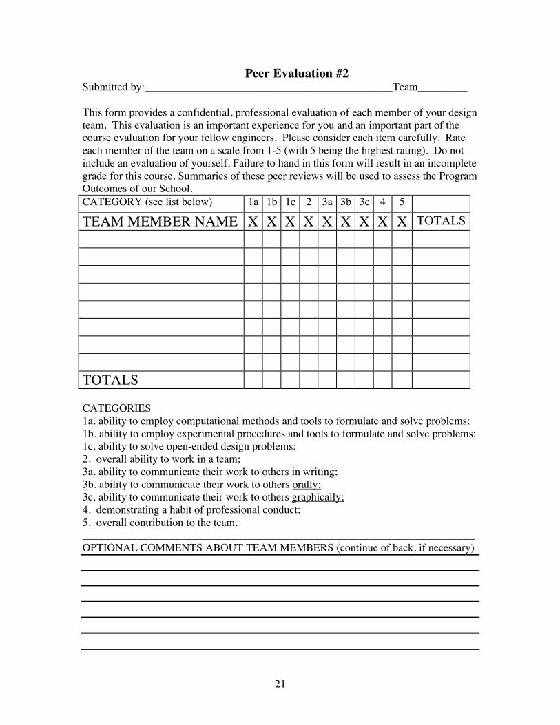
Peer Evaluation #2 Submitted by:_____________________________________________Team_________ This form provides a confidential, professional evaluation of each member of your design team. This evaluation is an important experience for you and an important part of the course evaluation for your fellow engineers. Please consider each item carefully. Rate each member of the team on a scale from 1-5 (with 5 being the highest rating). Do not include an evaluation of yourself. Failure to hand in this form will result in an incomplete grade for this course. Summaries of these peer reviews will be used to assess the Program Outcomes of our School. CATEGORY (see list below) 1a 1b 1c 2 3a 3b 3c 4 5 TEAM MEMBER NAME X X X X X X X X X TOTALS TOTALS CATEGORIES 1a. ability to employ computational methods and tools to formulate and solve problems; 1b. ability to employ experimental procedures and tools to formulate and solve problems; 1c. ability to solve open-ended design problems; 2. overall ability to work in a team; 3a. ability to communicate their work to others in writing; 3b. ability to communicate their work to others orally; 3c. ability to communicate their work to others graphically; 4. demonstrating a habit of professional conduct; 5. overall contribution to the team. _______________________________________________________________________ OPTIONAL COMMENTS ABOUT TEAM MEMBERS (continue of back, if necessary)

22

23
Peer Evaluation #1 Submitted by:_____________________________________________Team_________ This form provides a confidential, professional evaluation of each member of your design team. This evaluation is an important experience for you and an important part of the course evaluation for your fellow engineers. Please consider each item carefully. Rate each member of the team on a scale from 1-5 (with 5 being the highest rating). Do not include an evaluation of yourself. Failure to hand in this form will result in an incomplete grade for this course. Summaries of these peer reviews will be used to assess the Program Outcomes of our School. CATEGORY (see list below) 1a 1b 1c 2 3a 3b 3c 4 5 TEAM MEMBER NAME X X X X X X X X X TOTALS TOTALS CATEGORIES 1a. ability to employ computational methods and tools to formulate and solve problems; 1b. ability to employ experimental procedures and tools to formulate and solve problems; 1c. ability to solve open-ended design problems; 2. overall ability to work in a team; 3a. ability to communicate their work to others in writing; 3b. ability to communicate their work to others orally; 3c. ability to communicate their work to others graphically; 4. demonstrating a habit of professional conduct; 5. overall contribution to the team. _______________________________________________________________________ OPTIONAL COMMENTS ABOUT TEAM MEMBERS (continue of back, if necessary)

24