abb 1 · sectionalizing metering cubicle, type smc 17 wdi ht : 750 mm height: 1635 or 1885 mm bus...
TRANSCRIPT
UNIS 5 GB
1ABB
UNIS 5 GB
2 ABB
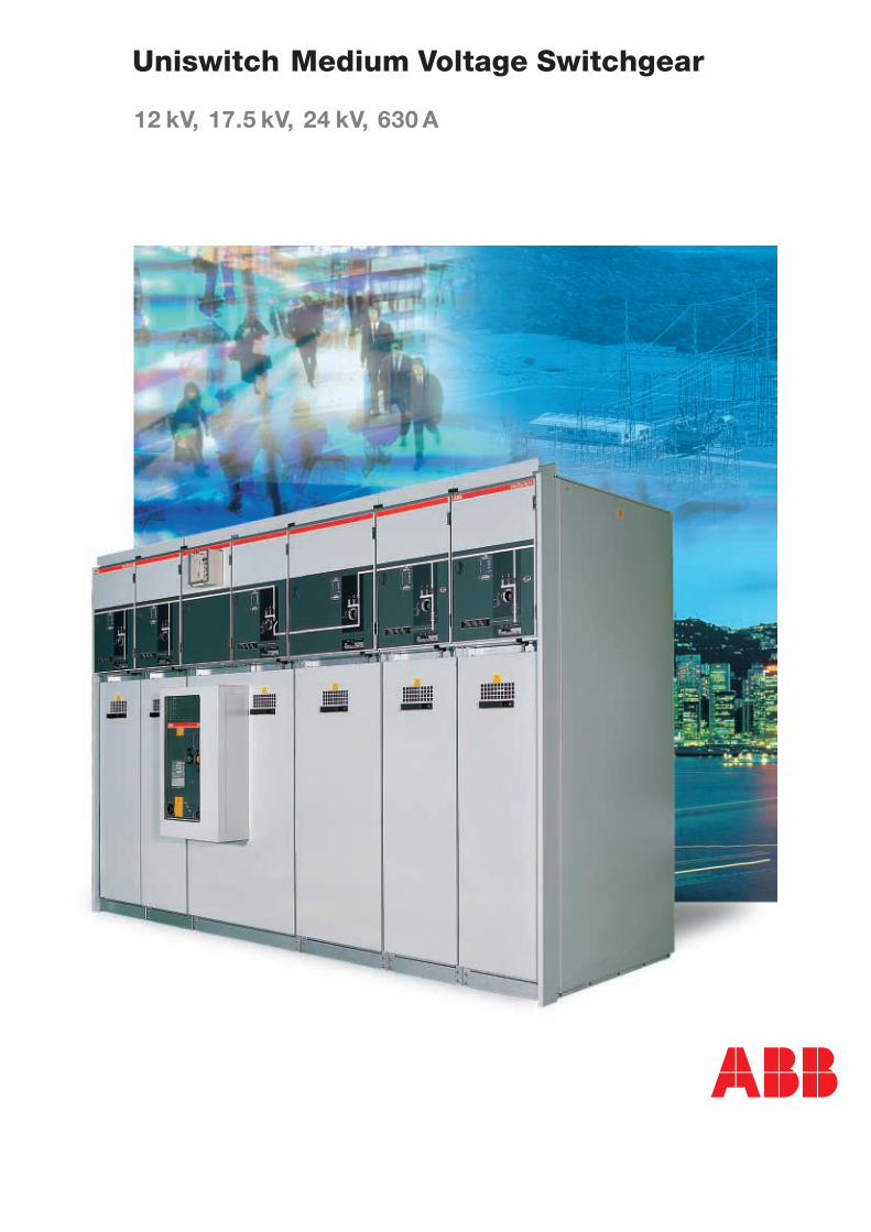
Uniswitch
Content
1. Design philosophy ............................... 3
2. Applications ......................................... 5
3. Switchgear construction ....................... 6
4. Cubicle types ........................................ 8
5. Components & accessories ............... 21
6. Technical data / dimensions ................ 39
7. Ordering example ............................... 46
UNIS 5 GB
3ABB
1.Uniswitch, need to say more?
Uniswitch
Design Philosophy
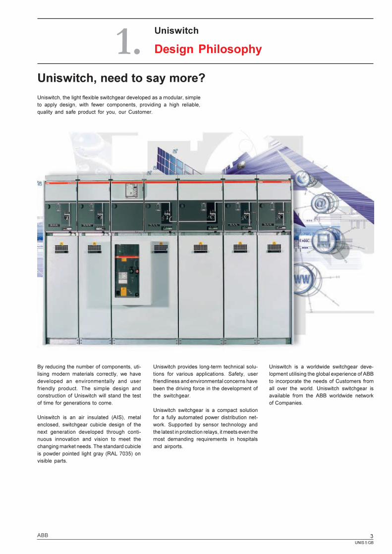
Uniswitch, the light flexible switchgear developed as a modular, simpleto apply design, with fewer components, providing a high reliable,quality and safe product for you, our Customer.
By reducing the number of components, uti-lising modern materials correctly, we havedeveloped an environmentally and userfriendly product. The simple design andconstruction of Uniswitch will stand the testof time for generations to come.
Uniswitch is an air insulated (AIS), metalenclosed, switchgear cubicle design of thenext generation developed through conti-nuous innovation and vision to meet thechanging market needs. The standard cubicleis powder pointed light gray (RAL 7035) onvisible parts.
Uniswitch provides long-term technical solu-tions for various applications. Safety, userfriendliness and environmental concerns havebeen the driving force in the development ofthe switchgear.
Uniswitch switchgear is a compact solutionfor a fully automated power distribution net-work. Supported by sensor technology andthe latest in protection relays, it meets even themost demanding requirements in hospitalsand airports.
Uniswitch is a worldwide switchgear deve-lopment utilising the global experience of ABBto incorporate the needs of Customers fromall over the world. Uniswitch switchgear isavailable from the ABB worldwide networkof Companies.
UNIS 5 GB
4 ABB
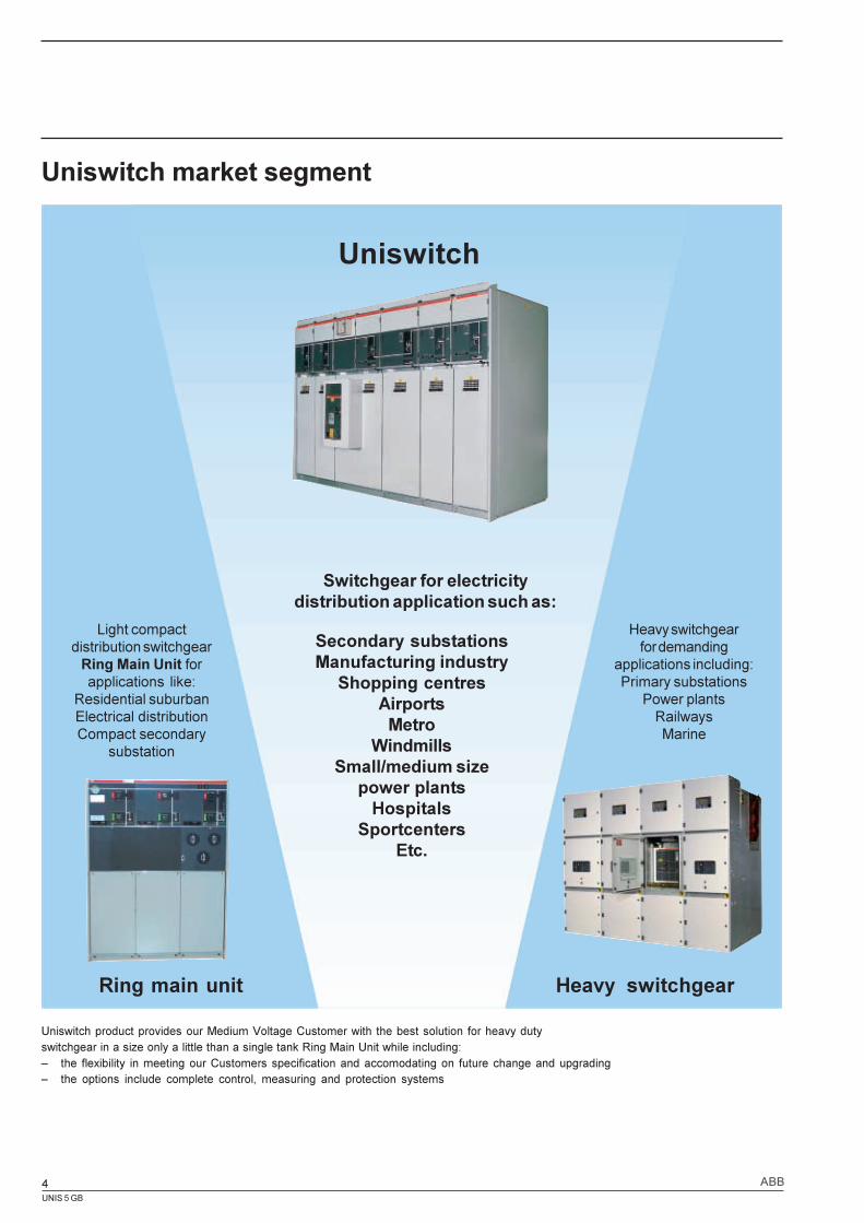
Uniswitch market segment
Ring main unit
Uniswitch
Heavy switchgear
Light compactdistribution switchgear
Ring Main Unit forapplications like:
Residential suburbanElectrical distributionCompact secondary
substation
Heavy switchgearfor demanding
applications including:Primary substations
Power plantsRailwaysMarine
Secondary substationsManufacturing industry
Shopping centresAirports
MetroWindmills
Small/medium sizepower plants
HospitalsSportcenters
Etc.
Switchgear for electricitydistribution application such as:
Uniswitch product provides our Medium Voltage Customer with the best solution for heavy dutyswitchgear in a size only a little than a single tank Ring Main Unit while including:� the flexibility in meeting our Customers specification and accomodating on future change and upgrading� the options include complete control, measuring and protection systems
UNIS 5 GB
5ABB
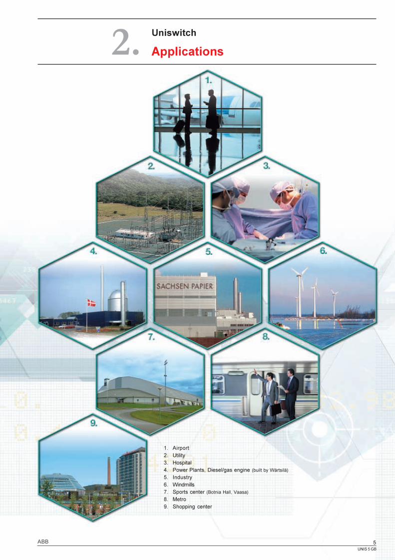
Uniswitch
Applications2.
1. Airport2. Utility3. Hospital4. Power Plants, Diesel/gas engine (built by Wärtsilä)
5. Industry6. Windmills7. Sports center (Botnia Hall, Vaasa)
8. Metro9. Shopping center
UNIS 5 GB
5ABB
UNIS 5 GB
6 ABB
3.
1
2
3
4
1
4
2
3
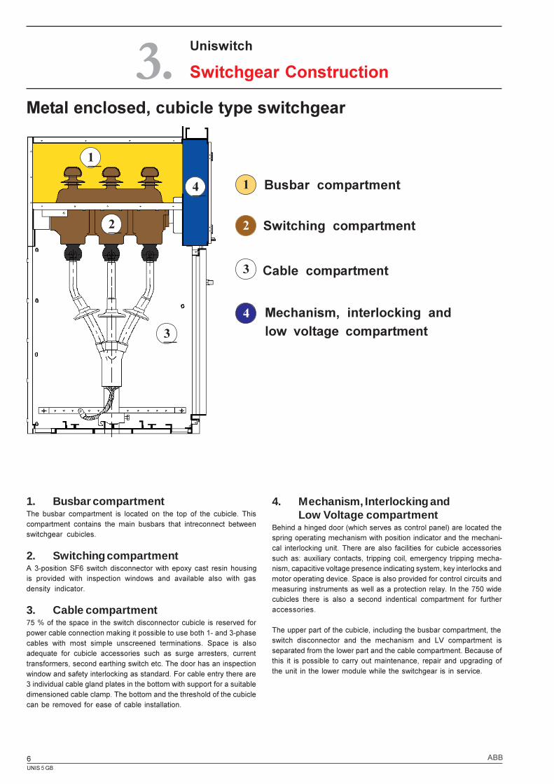
Metal enclosed, cubicle type switchgear
Uniswitch
Switchgear Construction
1. Busbar compartmentThe busbar compartment is located on the top of the cubicle. Thiscompartment contains the main busbars that intreconnect betweenswitchgear cubicles.
2. Switching compartmentA 3-position SF6 switch disconnector with epoxy cast resin housingis provided with inspection windows and available also with gasdensity indicator.
3. Cable compartment75 % of the space in the switch disconnector cubicle is reserved forpower cable connection making it possible to use both 1- and 3-phasecables with most simple unscreened terminations. Space is alsoadequate for cubicle accessories such as surge arresters, currenttransformers, second earthing switch etc. The door has an inspectionwindow and safety interlocking as standard. For cable entry there are3 individual cable gland plates in the bottom with support for a suitabledimensioned cable clamp. The bottom and the threshold of the cubiclecan be removed for ease of cable installation.
Busbar compartment
Switching compartment
Cable compartment
Mechanism, interlocking andlow voltage compartment
4. Mechanism, Interlocking andLow Voltage compartment
Behind a hinged door (which serves as control panel) are located thespring operating mechanism with position indicator and the mechani-cal interlocking unit. There are also facilities for cubicle accessoriessuch as: auxiliary contacts, tripping coil, emergency tripping mecha-nism, capacitive voltage presence indicating system, key interlocks andmotor operating device. Space is also provided for control circuits andmeasuring instruments as well as a protection relay. In the 750 widecubicles there is also a second indentical compartment for furtheraccessories.
The upper part of the cubicle, including the busbar compartment, theswitch disconnector and the mechanism and LV compartment isseparated from the lower part and the cable compartment. Because ofthis it is possible to carry out maintenance, repair and upgrading ofthe unit in the lower module while the switchgear is in service.
UNIS 5 GB
7ABB
1
2
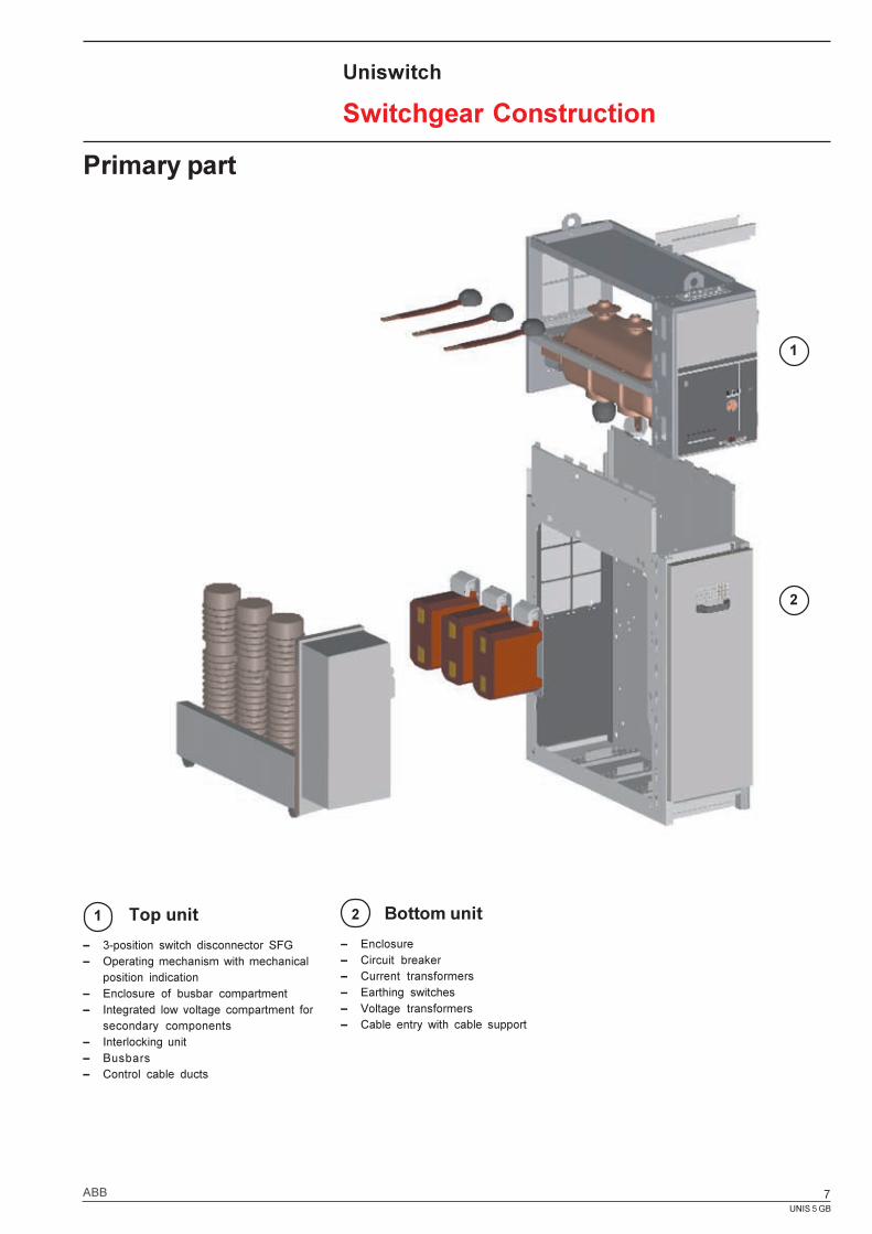
Primary part
1 Top unit
� 3-position switch disconnector SFG� Operating mechanism with mechanical
position indication� Enclosure of busbar compartment� Integrated low voltage compartment for
secondary components� Interlocking unit� Busbars� Control cable ducts
Uniswitch
Switchgear Construction
2 Bottom unit
� Enclosure� Circuit breaker� Current transformers� Earthing switches� Voltage transformers� Cable entry with cable support
UNIS 5 GB
8 ABB
4.1 Cubicle program ................................... 9
4.2 Switch Disconnector Cubicletype SDC............................................ 12
4.3 Switch Disconnector Cubiclewith fuse, type SDF ............................ 13
4.4 Circuit Breaker Cubicletype CBC............................................ 14
4.5 Direct Busbar Connectingtype DBC............................................ 15
4.6 Sectionalizing Cubicletype SEC............................................ 16
4.7 Bus Riser Cubicletype BRC............................................ 17
4.8 Sectionalizing Breaker Cubicletype SBC............................................ 18
4.9 Sectionalizing Metering Cubicletype SMC ........................................... 19
4.10 Bus Metering Cubicletype BMC ........................................... 20
Uniswitch
Cubicle Types4.
UNIS 5 GB
9ABB
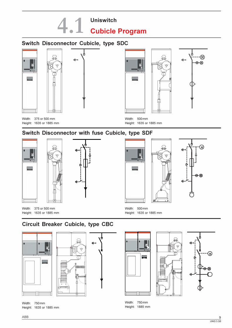
Circuit Breaker Cubicle, type CBC
Switch Disconnector Cubicle, type SDC
Width: 375 or 500 mmHeight: 1635 or 1885 mm
Switch Disconnector with fuse Cubicle, type SDF
Width: 375 or 500 mmHeight: 1635 or 1885 mm
Width: 750 mmHeight: 1635 or 1885 mm
Uniswitch
Cubicle Program
Width: 500 mmHeight: 1635 or 1885 mm
Width: 500 mmHeight: 1635 or 1885 mm
Width: 750 mmHeight: 1885 mm
4.1
UNIS 5 GB
10 ABB
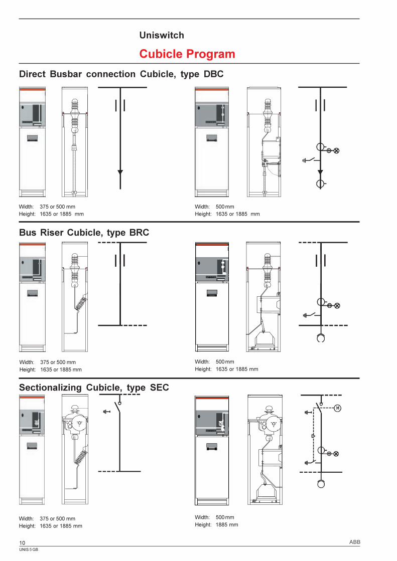
Direct Busbar connection Cubicle, type DBC
Width: 375 or 500 mmHeight: 1635 or 1885 mm
Bus Riser Cubicle, type BRC
Width: 375 or 500 mmHeight: 1635 or 1885 mm
Sectionalizing Cubicle, type SEC
Width: 375 or 500 mmHeight: 1635 or 1885 mm
Width: 500 mmHeight: 1635 or 1885 mm
Width: 500 mmHeight: 1635 or 1885 mm
Width: 500 mmHeight: 1885 mm
Uniswitch
Cubicle Program
UNIS 5 GB
11ABB
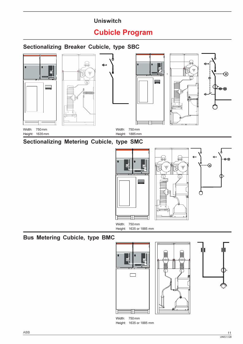
Sectionalizing Breaker Cubicle, type SBC
Width: 750 mmHeight: 1635 or 1885 mm
Uniswitch
Cubicle Program
Sectionalizing Metering Cubicle, type SMC
1 7
Width: 750 mmHeight: 1635 or 1885 mm
Bus Metering Cubicle, type BMC
Width: 750 mmHeight: 1635 mm
Width: 750 mmHeight: 1885 mm
UNIS 5 GB
12 ABB
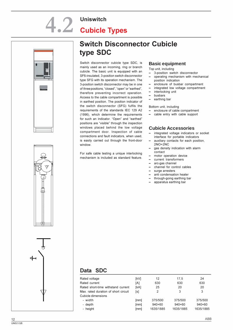
Switch Disconnector Cubicletype SDC
Uniswitch
Cubicle Types4.2
Basic equipmentTop unit, including� 3-position switch disconnector� operating mechanism with mechanical
position indication� enclosure of busbar compartment� integrated low voltage compartment� interlocking unit� busbars� earthing bar
Bottom unit, including� enclosure of cable compartment� cable entry with cable support
Cubicle Accessories� integrated voltage indicators or socket
interface for portable indicators� auxiliary contacts for each position,
2NO+2NC� gas density indication with alarm
contact� motor operation device� current transformers� arc-gas channel� channel for control cables� surge arresters� anti condensation heater� through-going earthing bar� apparatus earthing bar
Data SDCRated voltage [kV] 12 17,5 24Rated current [A] 630 630 630Rated short-time withstand current [kA] 25 20 20Max. rated duration of short circuit [s] 2 3 3Cubicle dimensions
- width [mm] 375/500 375/500 375/500- depth [mm] 940+60 940+60 940+60- height [mm] 1635/1885 1635/1885 1635/1885
Switch disconnector cubicle type SDC, ismainly used as an incoming, ring or branchcubicle. The basic unit is equipped with anSF6-insulated, 3-position switch disconnectortype SFG with its operation mechanism. The3-position switch disconnector may be in oneof three positions, �closed�, �open� or �earthed�,therefore preventing incorrect operation.Access to the cable compartment is possiblein earthed position. The position indicator ofthe switch disconnector (SFG) fulfils therequirements of the standards IEC 129 A2(1996), which determine the requirementsfor such an indicator. �Open� and �earthed�positions are �visible� through the inspectionwindows placed behind the low voltagecompartment door. Inspection of cableconnections and fault indicators, when used,is easily carried out through the front-doorwindow.
For safe cable testing a unique interlockingmechanism is included as standard feature.
UNIS 5 GB
13ABB
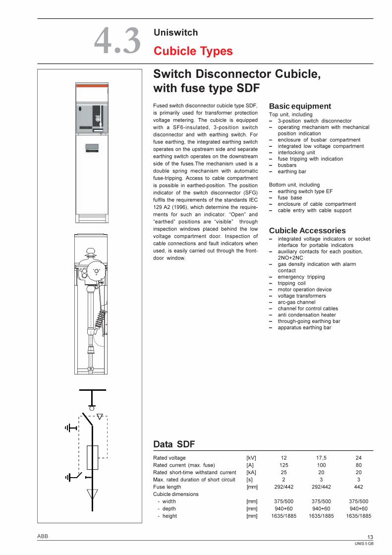
Switch Disconnector Cubicle,with fuse type SDF
Data SDFRated voltage [kV] 12 17,5 24Rated current (max. fuse) [A] 125 100 80Rated short-time withstand current [kA] 25 20 20Max. rated duration of short circuit [s] 2 3 3Fuse length [mm] 292/442 292/442 442Cubicle dimensions
- width [mm] 375/500 375/500 375/500- depth [mm] 940+60 940+60 940+60- height [mm] 1635/1885 1635/1885 1635/1885
Uniswitch
Cubicle Types4.3
Fused switch disconnector cubicle type SDF,is primarily used for transformer protectionvoltage metering. The cubicle is equippedwith a SF6-insulated, 3-position switchdisconnector and with earthing switch. Forfuse earthing, the integrated earthing switchoperates on the upstream side and separateearthing switch operates on the downstreamside of the fuses.The mechanism used is adouble spring mechanism with automaticfuse-tripping. Access to cable compartmentis possible in earthed-position. The positionindicator of the switch disconnector (SFG)fulfils the requirements of the standards IEC129 A2 (1996), which determine the require-ments for such an indicator. �Open� and�earthed� positions are �visible� throughinspection windows placed behind the lowvoltage compartment door. Inspection ofcable connections and fault indicators whenused, is easily carried out through the front-door window.
Basic equipmentTop unit, including� 3-position switch disconnector� operating mechanism with mechanical
position indication� enclosure of busbar compartment� integrated low voltage compartment� interlocking unit� fuse tripping with indication� busbars� earthing bar
Bottom unit, including� earthing switch type EF� fuse base� enclosure of cable compartment� cable entry with cable support
Cubicle Accessories� integrated voltage indicators or socket
interface for portable indicators� auxiliary contacts for each position,
2NO+2NC� gas density indication with alarm
contact� emergency tripping� tripping coil� motor operation device� voltage transformers� arc-gas channel� channel for control cables� anti condensation heater� through-going earthing bar� apparatus earthing bar
UNIS 5 GB
14 ABB
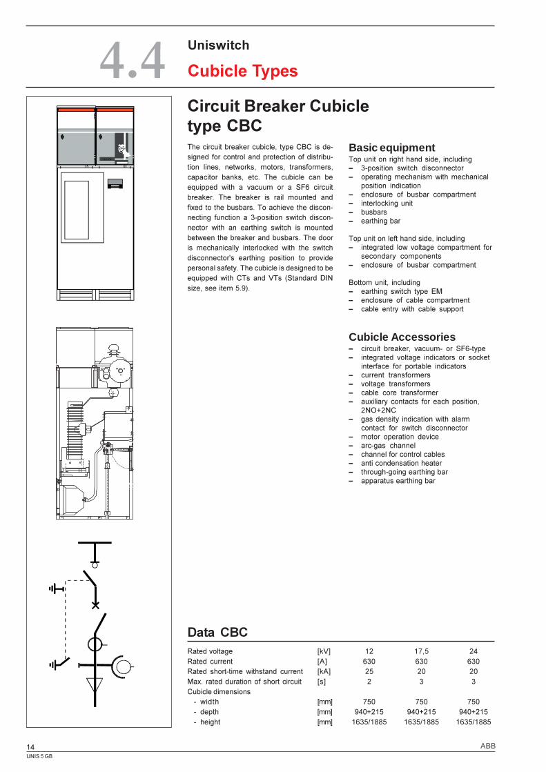
Circuit Breaker Cubicletype CBC
Data CBCRated voltage [kV] 12 17,5 24Rated current [A] 630 630 630Rated short-time withstand current [kA] 25 20 20Max. rated duration of short circuit [s] 2 3 3Cubicle dimensions
- width [mm] 750 750 750- depth [mm] 940+215 940+215 940+215- height [mm] 1635/1885 1635/1885 1635/1885
Uniswitch
Cubicle Types4.4Basic equipmentTop unit on right hand side, including� 3-position switch disconnector� operating mechanism with mechanical
position indication� enclosure of busbar compartment� interlocking unit� busbars� earthing bar
Top unit on left hand side, including� integrated low voltage compartment for
secondary components� enclosure of busbar compartment
Bottom unit, including� earthing switch type EM� enclosure of cable compartment� cable entry with cable support
Cubicle Accessories� circuit breaker, vacuum- or SF6-type� integrated voltage indicators or socket
interface for portable indicators� current transformers� voltage transformers� cable core transformer� auxiliary contacts for each position,
2NO+2NC� gas density indication with alarm
contact for switch disconnector� motor operation device� arc-gas channel� channel for control cables� anti condensation heater� through-going earthing bar� apparatus earthing bar
The circuit breaker cubicle, type CBC is de-signed for control and protection of distribu-tion lines, networks, motors, transformers,capacitor banks, etc. The cubicle can beequipped with a vacuum or a SF6 circuitbreaker. The breaker is rail mounted andfixed to the busbars. To achieve the discon-necting function a 3-position switch discon-nector with an earthing switch is mountedbetween the breaker and busbars. The dooris mechanically interlocked with the switchdisconnector's earthing position to providepersonal safety. The cubicle is designed to beequipped with CTs and VTs (Standard DINsize, see item 5.9).
UNIS 5 GB
15ABB
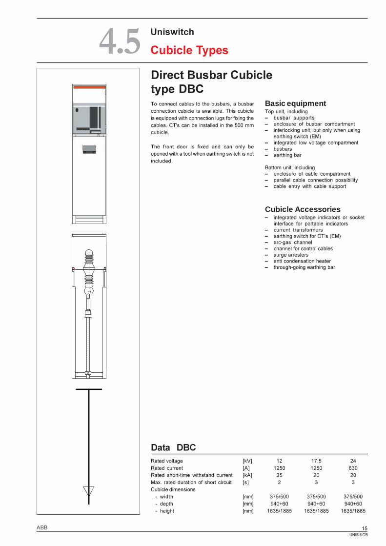
Direct Busbar Cubicletype DBC
Uniswitch
Cubicle Types4.5Basic equipmentTop unit, including� busbar supports� enclosure of busbar compartment� interlocking unit, but only when using
earthing switch (EM)� integrated low voltage compartment� busbars� earthing bar
Bottom unit, including� enclosure of cable compartment� parallel cable connection possibility� cable entry with cable support
Cubicle Accessories� integrated voltage indicators or socket
interface for portable indicators� current transformers� earthing switch for CT�s (EM)� arc-gas channel� channel for control cables� surge arresters� anti condensation heater� through-going earthing bar
Data DBCRated voltage [kV] 12 17,5 24Rated current [A] 1250 1250 630Rated short-time withstand current [kA] 25 20 20Max. rated duration of short circuit [s] 2 3 3Cubicle dimensions
- width [mm] 375/500 375/500 375/500- depth [mm] 940+60 940+60 940+60- height [mm] 1635/1885 1635/1885 1635/1885
To connect cables to the busbars, a busbarconnection cubicle is available. This cubicleis equipped with connection lugs for fixing thecables. CT's can be installed in the 500 mmcubicle.
The front door is fixed and can only beopened with a tool when earthing switch is notincluded.
UNIS 5 GB
16 ABB
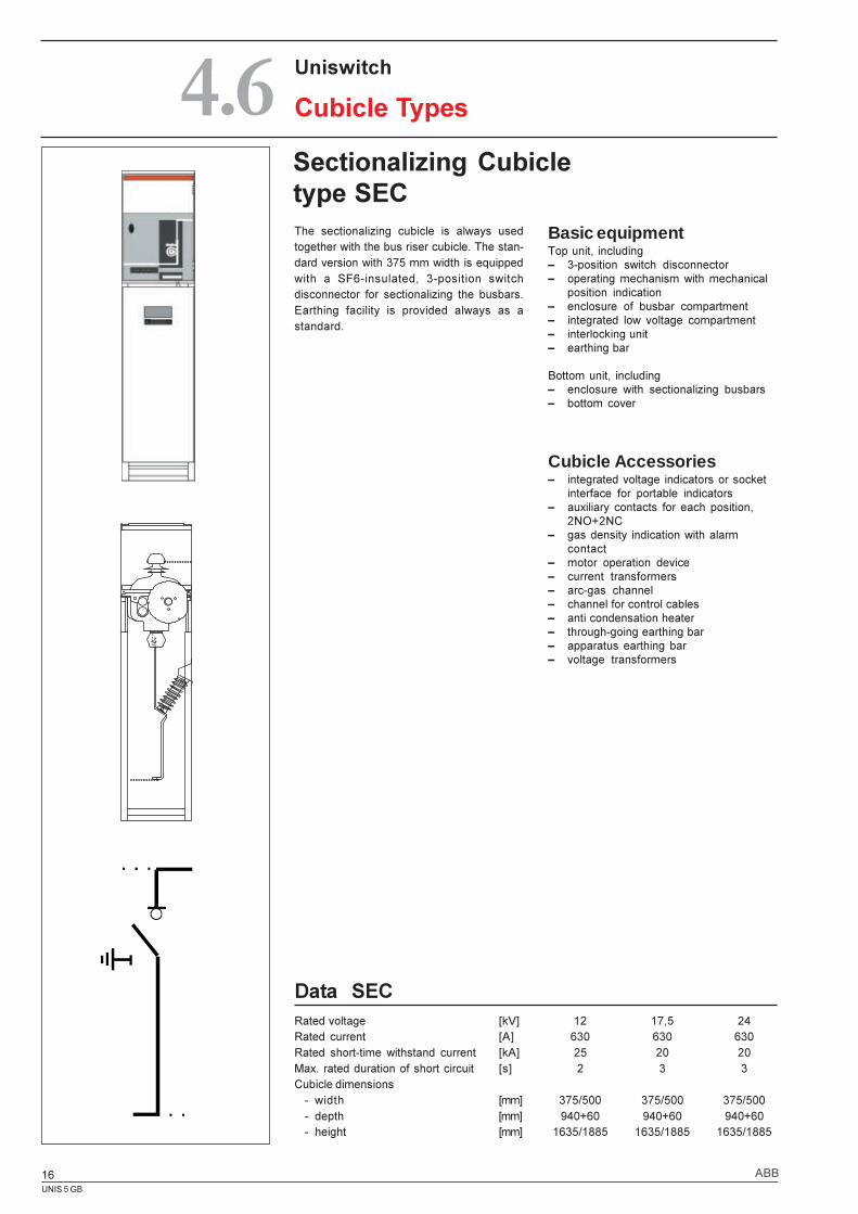
Data SECRated voltage [kV] 12 17,5 24Rated current [A] 630 630 630Rated short-time withstand current [kA] 25 20 20Max. rated duration of short circuit [s] 2 3 3Cubicle dimensions
- width [mm] 375/500 375/500 375/500- depth [mm] 940+60 940+60 940+60- height [mm] 1635/1885 1635/1885 1635/1885
Sectionalizing Cubicletype SEC
4.6 Uniswitch
Cubicle Types
Basic equipmentTop unit, including� 3-position switch disconnector� operating mechanism with mechanical
position indication� enclosure of busbar compartment� integrated low voltage compartment� interlocking unit� earthing bar
Bottom unit, including� enclosure with sectionalizing busbars� bottom cover
Cubicle Accessories� integrated voltage indicators or socket
interface for portable indicators� auxiliary contacts for each position,
2NO+2NC� gas density indication with alarm
contact� motor operation device� current transformers� arc-gas channel� channel for control cables� anti condensation heater� through-going earthing bar� apparatus earthing bar� voltage transformers
The sectionalizing cubicle is always usedtogether with the bus riser cubicle. The stan-dard version with 375 mm width is equippedwith a SF6-insulated, 3-position switchdisconnector for sectionalizing the busbars.Earthing facility is provided always as astandard.
UNIS 5 GB
17ABB
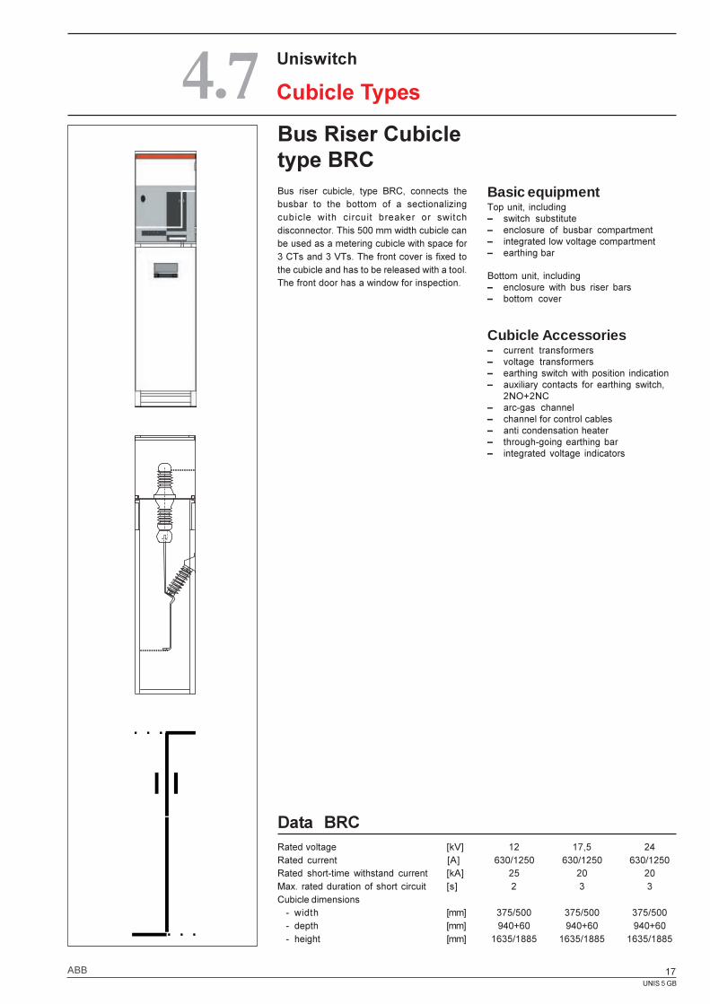
Bus Riser Cubicletype BRC
Data BRCRated voltage [kV] 12 17,5 24Rated current [A] 630/1250 630/1250 630/1250Rated short-time withstand current [kA] 25 20 20Max. rated duration of short circuit [s] 2 3 3Cubicle dimensions
- width [mm] 375/500 375/500 375/500- depth [mm] 940+60 940+60 940+60- height [mm] 1635/1885 1635/1885 1635/1885
Uniswitch
Cubicle Types4.7
Basic equipmentTop unit, including� switch substitute� enclosure of busbar compartment� integrated low voltage compartment� earthing bar
Bottom unit, including� enclosure with bus riser bars� bottom cover
Cubicle Accessories� current transformers� voltage transformers� earthing switch with position indication� auxiliary contacts for earthing switch,
2NO+2NC� arc-gas channel� channel for control cables� anti condensation heater� through-going earthing bar� integrated voltage indicators
Bus riser cubicle, type BRC, connects thebusbar to the bottom of a sectionalizingcubicle with circuit breaker or switchdisconnector. This 500 mm width cubicle canbe used as a metering cubicle with space for3 CTs and 3 VTs. The front cover is fixed tothe cubicle and has to be released with a tool.The front door has a window for inspection.
UNIS 5 GB
18 ABB
Uniswitch
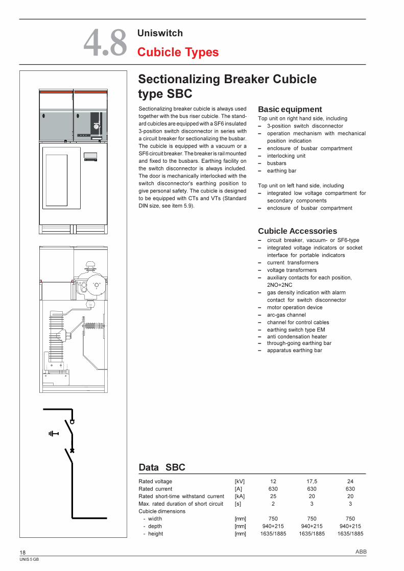
Cubicle Types4.8Sectionalizing Breaker Cubicletype SBC
Data SBCRated voltage [kV] 12 17,5 24Rated current [A] 630 630 630Rated short-time withstand current [kA] 25 20 20Max. rated duration of short circuit [s] 2 3 3Cubicle dimensions
- width [mm] 750 750 750- depth [mm] 940+215 940+215 940+215- height [mm] 1635/1885 1635/1885 1635/1885
Sectionalizing breaker cubicle is always usedtogether with the bus riser cubicle. The stand-ard cubicles are equipped with a SF6 insulated3-position switch disconnector in series witha circuit breaker for sectionalizing the busbar.The cubicle is equipped with a vacuum or aSF6 circuit breaker. The breaker is rail mountedand fixed to the busbars. Earthing facility onthe switch disconnector is always included.The door is mechanically interlocked with theswitch disconnector's earthing position togive personal safety. The cubicle is designedto be equipped with CTs and VTs (StandardDIN size, see item 5.9).
Basic equipmentTop unit on right hand side, including� 3-position switch disconnector� operation mechanism with mechanical
position indication� enclosure of busbar compartment� interlocking unit� busbars� earthing bar
Top unit on left hand side, including� integrated low voltage compartment for
secondary components� enclosure of busbar compartment
Cubicle Accessories� circuit breaker, vacuum- or SF6-type� integrated voltage indicators or socket
interface for portable indicators� current transformers� voltage transformers� auxiliary contacts for each position,
2NO+2NC� gas density indication with alarm
contact for switch disconnector� motor operation device� arc-gas channel� channel for control cables� earthing switch type EM� anti condensation heater� through-going earthing bar� apparatus earthing bar
UNIS 5 GB
19ABB
Uniswitch
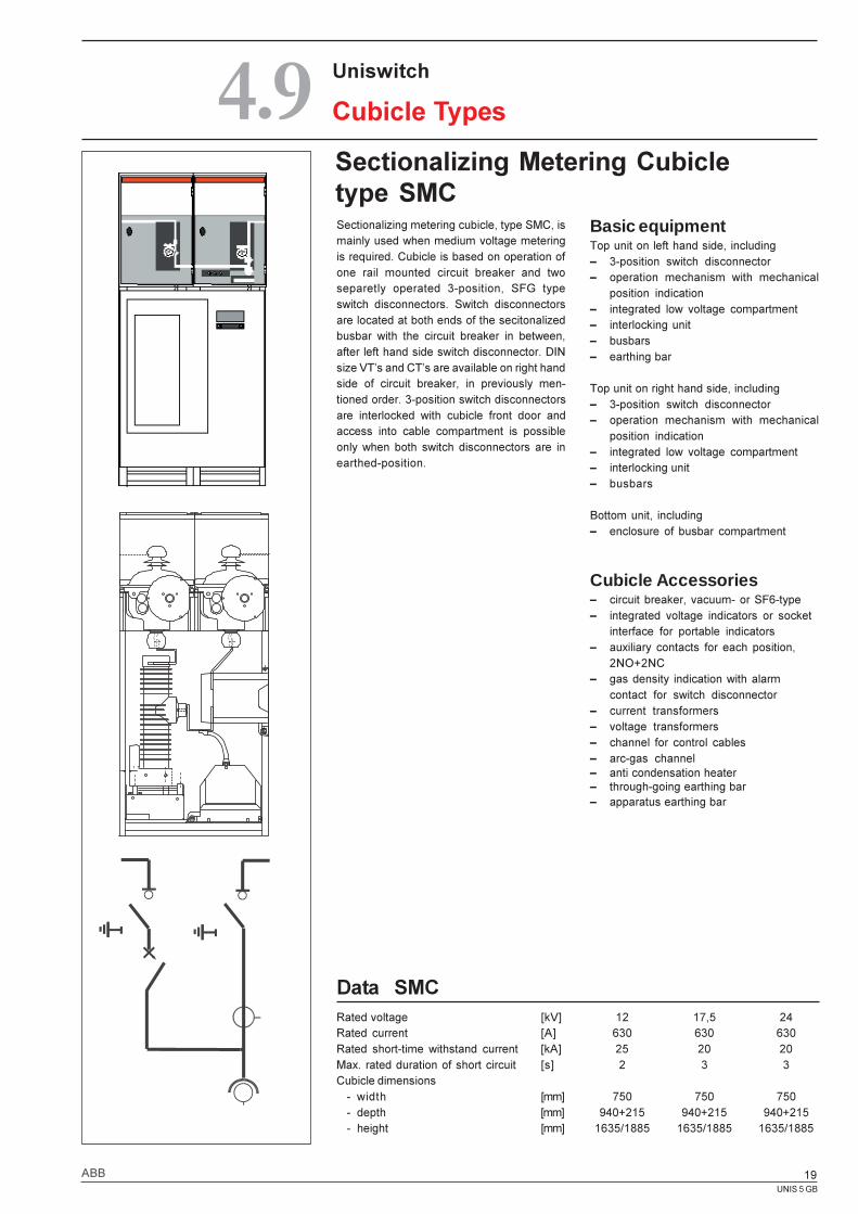
Cubicle Types4.9Sectionalizing Metering Cubicletype SMC
Data SMCRated voltage [kV] 12 17,5 24Rated current [A] 630 630 630Rated short-time withstand current [kA] 25 20 20Max. rated duration of short circuit [s] 2 3 3Cubicle dimensions
- width [mm] 750 750 750- depth [mm] 940+215 940+215 940+215- height [mm] 1635/1885 1635/1885 1635/1885
Sectionalizing metering cubicle, type SMC, ismainly used when medium voltage meteringis required. Cubicle is based on operation ofone rail mounted circuit breaker and twoseparetly operated 3-position, SFG typeswitch disconnectors. Switch disconnectorsare located at both ends of the secitonalizedbusbar with the circuit breaker in between,after left hand side switch disconnector. DINsize VT�s and CT�s are available on right handside of circuit breaker, in previously men-tioned order. 3-position switch disconnectorsare interlocked with cubicle front door andaccess into cable compartment is possibleonly when both switch disconnectors are inearthed-position.
Basic equipmentTop unit on left hand side, including� 3-position switch disconnector� operation mechanism with mechanical
position indication� integrated low voltage compartment� interlocking unit� busbars� earthing bar
Top unit on right hand side, including� 3-position switch disconnector� operation mechanism with mechanical
position indication� integrated low voltage compartment� interlocking unit� busbars
Bottom unit, including� enclosure of busbar compartment
Cubicle Accessories� circuit breaker, vacuum- or SF6-type� integrated voltage indicators or socket
interface for portable indicators� auxiliary contacts for each position,
2NO+2NC� gas density indication with alarm
contact for switch disconnector� current transformers� voltage transformers� channel for control cables� arc-gas channel� anti condensation heater� through-going earthing bar� apparatus earthing bar
1 7
UNIS 5 GB
20 ABB
Uniswitch
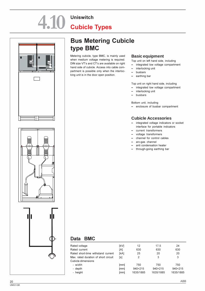
Cubicle Types4.10Bus Metering Cubicletype BMC
Data BMCRated voltage [kV] 12 17,5 24Rated current [A] 630 630 630Rated short-time withstand current [kA] 25 20 20Max. rated duration of short circuit [s] 2 3 3Cubicle dimensions
- width [mm] 750 750 750- depth [mm] 940+215 940+215 940+215- height [mm] 1635/1885 1635/1885 1635/1885
Metering cubicle, type BMC, is mainly usedwhen medium voltage metering is required.DIN size VT�s and CT�s are available on righthand side of cubicle. Access into cable com-partment is possible only when the interloc-king unit is in the door open position.
Basic equipmentTop unit on left hand side, including� integrated low voltage compartment� interlocking unit� busbars� earthing bar
Top unit on right hand side, including� integrated low voltage compartment� interlocking unit� busbars
Bottom unit, including� enclosure of busbar compartment
Cubicle Accessories� integrated voltage indicators or socket
interface for portable indicators� current transformers� voltage transformers� channel for control cables� arc-gas channel� anti condensation heater� through-going earthing bar
UNIS 5 GB
21ABB
5.1 Mechanism,types single and double spring ............. 22
5.2 Switch disconnector, type SFG ........... 23
5.3 Busbar arrangement ............................ 24
5.4 Motor operation ofswitch disconnector ............................. 25
5.5 Earthing switches................................. 26
5.6 Vacuum Circuit Breaker VD4-S ............ 27
5.7 SF6-Circuit Breaker, HD4/S ................. 28
5.8 Fuse link type CEF............................... 29
5.9 Current and voltage transformers,Sensor Technology .............................. 30
5.10 Low voltage compartment .................... 34
5.11 Voltage presence indicating systemand Relays........................................... 35
5.12 Control cable entries ............................ 37
5.13 Arc gas channel ................................... 38
Uniswitch
Components & Accessories5.
UNIS 5 GB
22 ABB
Uniswitch
Components & Accessories5.1Mechanism
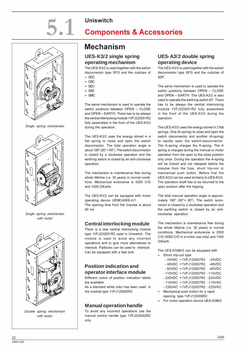
UES-A3/2 double springoperating deviceThe UES-A3/2 is used together with the switchdisconnector type SFG and the cubicles ofSDF.
The same mechanism is used to operate theswitch positions between OPEN � CLOSEand OPEN � EARTH. The UES-A3/2 is alsoused to operate the earthing switch EF. Therehas to be always the central interlockingmodule 1VFJ220001R2 fully assembledin the front of the UES-A3/2 during theoperation.
The UES-A3/2 uses the energy stored in 2 flatsprings. One (K-spring) to close and open theswitch disconnector and another (A-spring)to rapidly open the switch-disconnector.The A-spring charges the K-spring. The Aspring is charged during the manual or motoroperation from the open to the close positiononly once. During the operation the A-springwill be locked and not released before theimpulse from the fuse, shunt trip-coil ormechanical push button. Before that theUES-A3/2 can be used similarly to UES-K3/2.The operation shaft has to be returned to theopen position after the tripping.
The total manual operation angle is approxi-mately 180° (90°+ 90°). The switch iscon-nector is closed by a clockwise operation andthe earthing switch is closed by an anti-clockwise operation.
The mechanism is maintenance free duringthe whole lifetime (i.e. 30 years) in normalconditions. Mechanical endurance is 2000C/O (5000 C/O in a motor use only) and 1000O/Earth.
The UES-A3(M)/2 can be equipped with� Shunt trip-coil type
- 24VDC =1VFJ120007R2 -24VDC- 48VDC =1VFJ120007R2 -48VDC- 60VDC =1VFJ120007R2 -60VDC
- 110VDC =1VFJ120007R2 -110VDC- 220VDC =1VFJ120007R2 -220VDC- 110VAC =1VFJ120007R2 -110VAC- 230VAC =1VFJ120007R2 -230VAC
� Mechanical push button for a rapidopening, type 1VFJ120006R2
� For motor operation device UES-A3M/2
UES-K3/2 single springoperating mechanismThe UES-K3/2 is used together with the switchdisconnector type SFG and the cubicles of� SDC� CBC� SEC� SBC� SMC
The same mechanism is used to operate theswitch positions between OPEN � CLOSEand OPEN � EARTH. There has to be alwaysthe central interlocking module 1VFJ220001R2fully assembled in the front of the UES-K3/2during the operation.
The UES-K3/2 uses the energy stored in aflat spring to close and open the switchdisconnector. The total operation angle isabout 180° (90° + 90°). The switch disconnectoris closed by a clockwise operation and theearthing switch is closed by an anti-clockwiseoperation.
The mechanism is maintenance free duringwhole lifetime (i.e. 30 years) in normal condi-tions. Mechanical endurance is 5000 C/Oand 1000 O/Earth.
The UES-K3/2 can be equipped with motoroperating device UEMC40K8-U/1.The opening time from the impulse is about40 ms.
Central interlocking moduleThere is a new central interlocking moduletype 1VFJ220001R2 used in Uniswitch. Themodule is used to avoid any incorrectoperations and to give more alternatives tointerlock. Padlocks can be used to interlock.Can be equipped with a fast lock.
Position indication andoperator interface moduleDifferent colors of position indication labelsare available.As a standard white color has been used inthe module type 1VFJ120005R2.
Manual operation handleTo avoid any incorrect operations use themanual control handle type 1VFJ220002R2only.
Single spring mechanism
Single spring mechanismwith motor
Double spring mechanismwith motor
UNIS 5 GB
23ABB
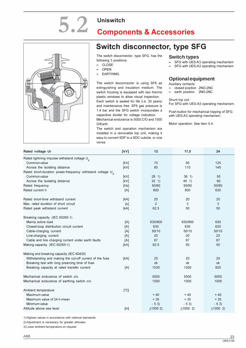
Switch disconnector, type SFGThe switch disconnector, type SFG, has thefollowing 3 positions:� CLOSE� OPEN� EARTHING
The switch disconnector is using SF6 asextinguishing and insulation medium. Theswitch housing is equipped with two thermoplastic windows to allow visual inspection.Each switch is sealed for life (i.e. 30 years)and maintenance free. SF6 gas pressure is1.4 bar and the SFG switch incorporates acapacitive divider for voltage indication.Mechanical endurance is 5000 C/O and 1000O/Earth.The switch and operation mechanism areinstalled in a removable top unit, making iteasy to convert SDF to a SDC cubicle, or viceversa.
Switch types� SFG with UES-K3 operating mechanism� SFG with UES-A3 operating mechanism
Optional equipmentAuxiliary contacts:� closed position 2NO-2NC� earth position 2NO-2NC
Shunt trip coil:For SFG with UES-A3 operating mechanism.
Push-button for mechanical tripping of SFGwith UES-A3 operating mechanism.
Motor operation: See item 5.4.
Uniswitch
Components & Accessories5.2
Rated voltage Ur [kV] 12 17,5 24
Rated lightning impulse withstand voltage Up
Common value [kV] 75 95 125Across the isolating distance [kV] 85 110 145
Rated short-duration power-frequency withstand voltage Ud
Common value [kV] 28 1) 38 1) 50Across the isolating distance [kV] 32 1) 45 1) 60
Rated frequency [Hz] 50/60 50/60 50/60Rated current Ir [A] 800 800 630
Rated short-time withstand current [kA] 25 20 20Max. rated duration of short circuit [s] 2 3 3Rated peak withstand current [kA] 62,5 50 50
Breaking capacity (IEC 60265-1)Mainly active load [A] 630/800 630/800 630Closed-loop distribution circuit current [A] 630 630 630Cable-charging current [A] 50/10 50/10 50/10Line-charging current [A] 20 20 20Cable and line charging current under earth faults [A] 87 87 87
Making capacity (IEC 60265-1) [kA] 62,5 50 50
Making and breaking capacity (IEC 60420)Withstanding and making the cut-off current of the fuse [kA] 25 20 20Breaking test with long prearcing time of fuse ok ok okBreaking capacity at rated transfer current [A] 1530 1260 920
Mechanical endurance of switch c/o 5000 5000 5000Mechanical endurance of earthing switch c/o 1000 1000 1000
Ambient temperature [°C]Maximum value + 40 + 40 + 40Maximum value of 24 h-mean + 35 + 35 + 35Minimum value - 5 3) - 5 3) - 5 3)
Altitude above sea level [m] <1000 2) <1000 2) <1000 2)
1) Highest values in accordance with national standards.
2) Adjustment is necessary for greater altitudes.
3) Lower ambient temperature on request.
UNIS 5 GB
24 ABB
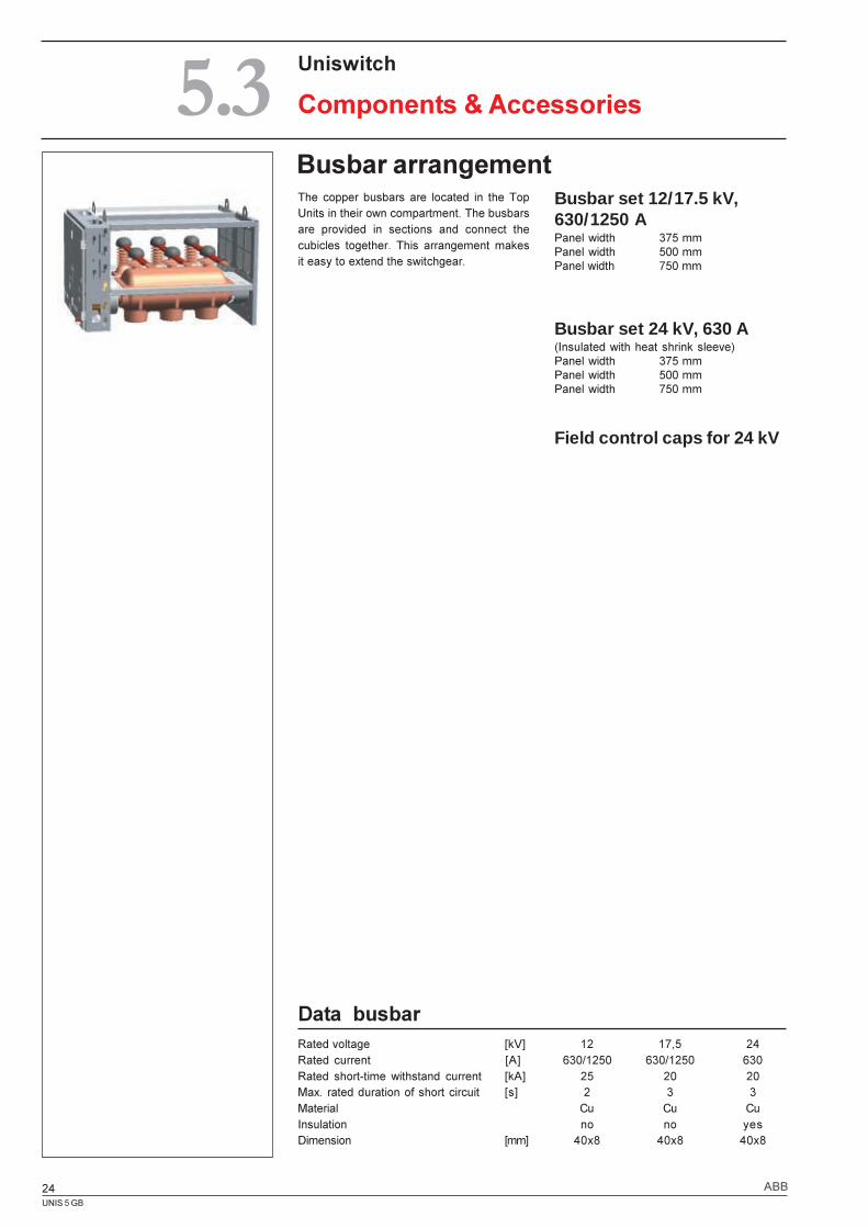
Busbar arrangementThe copper busbars are located in the TopUnits in their own compartment. The busbarsare provided in sections and connect thecubicles together. This arrangement makesit easy to extend the switchgear.
Busbar set 12/17.5 kV,630/1250 APanel width 375 mmPanel width 500 mmPanel width 750 mm
Busbar set 24 kV, 630 A(Insulated with heat shrink sleeve)Panel width 375 mmPanel width 500 mmPanel width 750 mm
Field control caps for 24 kV
Uniswitch
Components & Accessories5.3
Data busbarRated voltage [kV] 12 17,5 24Rated current [A] 630/1250 630/1250 630Rated short-time withstand current [kA] 25 20 20Max. rated duration of short circuit [s] 2 3 3Material Cu Cu CuInsulation no no yesDimension [mm] 40x8 40x8 40x8
UNIS 5 GB
25ABB
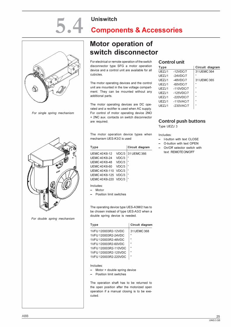
Motor operation ofswitch disconnector
For single spring mechanism
Uniswitch
Components & Accessories5.4For electrical or remote operation of the switchdisconnector type SFG a motor operationdevice and a control unit are available for allcubicles.
The motor operating devices and the controlunit are mounted in the low voltage compart-ment. They can be mounted without anyadditional parts.
The motor operating devices are DC ope-rated and a rectifier is used when AC supply.For control of motor operating device 2NO+ 2NC aux. contacts on switch disconnectorare required.
The motor operation device types whenmechanism UES-K3/2 is used
Type Circuit diagram
UEMC 40 K8-12 VDC/3 31 UEMC 366UEMC 40 K8-24 VDC/3 �UEMC 40 K8-48 VDC/3 �UEMC 40 K8-60 VDC/3 �UEMC 40 K8-110 VDC/3 �UEMC 40 K8-125 VDC/3 �UEMC 40 K8-220 VDC/3 �
Includes:� Motor� Position limit switches
The operating device type UES-A3M/2 has tobe chosen instead of type UES-A3/2 when adouble spring device is needed.
Control unitType Circuit diagramUEZJ 1 -12VDC/7 31 UEMC 364UEZJ 1 -24VDC/7 �UEZJ 1 -48VDC/7 31 UEMC 365UEZJ 1 -60VDC/7 �UEZJ 1 -110VDC/7 �UEZJ 1 -125VDC/7 �UEZJ 1 -220VDC/7 �UEZJ 1 -110VAC/7 �UEZJ 1 -230VAC/7 �
Control push buttonsType UEZJ 3
Includes:� I-button with text CLOSE� O-button with text OPEN� On/Off selector switch with
text REMOTE ON/OFF
For double spring mechanism
Type Circuit diagram
1VFU 120003R2-12VDC 31 UEMC 3681VFU 120003R2-24VDC "1VFU 120003R2-48VDC "1VFU 120003R2-60VDC "1VFU 120003R2-110VDC "1VFU 120003R2-125VDC "1VFU 120003R2-220VDC "
Includes:� Motor + double spring device� Position limit switches
The operation shaft has to be returned tothe open position after the motorized openoperation if a manual closing is to be exe-cuted.
UNIS 5 GB
26 ABB
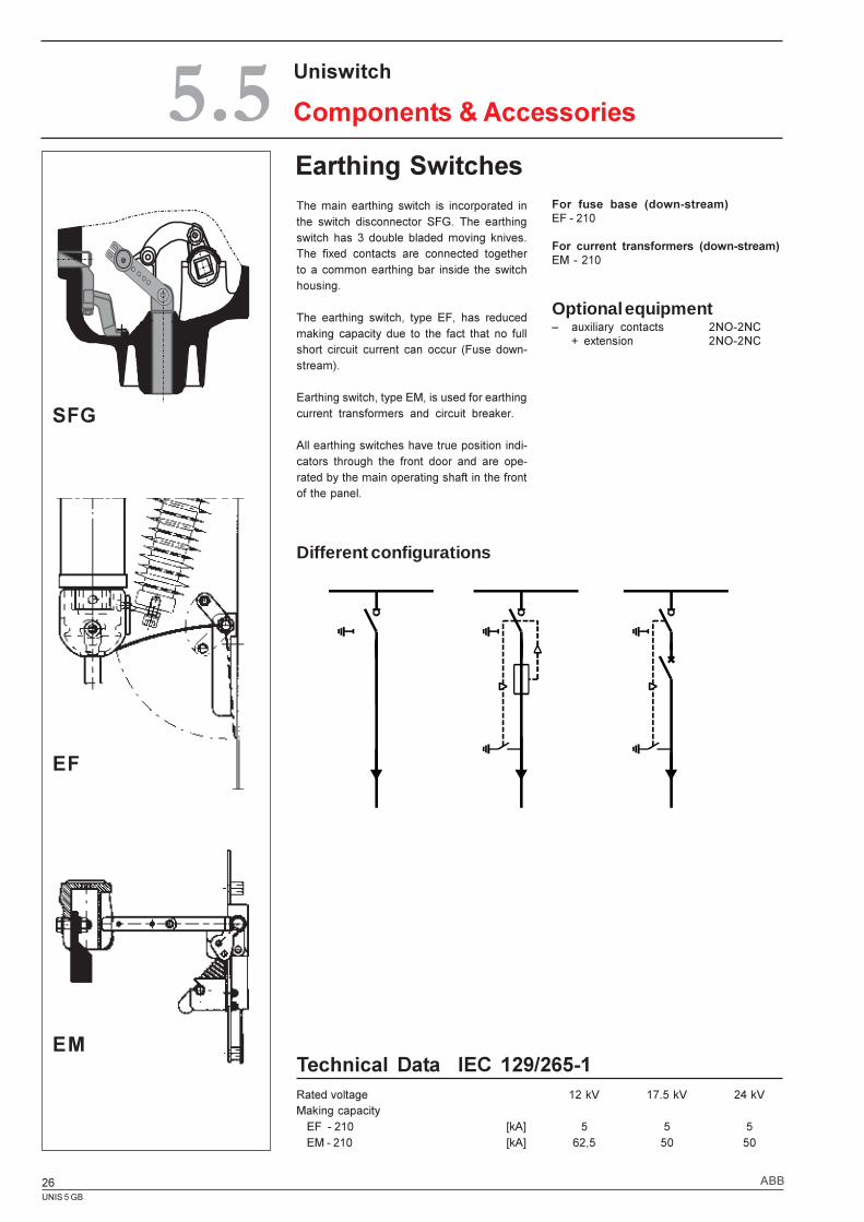
Earthing Switches
Technical Data IEC 129/265-1Rated voltage 12 kV 17.5 kV 24 kVMaking capacity
EF - 210 [kA] 5 5 5EM - 210 [kA] 62,5 50 50
The main earthing switch is incorporated inthe switch disconnector SFG. The earthingswitch has 3 double bladed moving knives.The fixed contacts are connected togetherto a common earthing bar inside the switchhousing.
The earthing switch, type EF, has reducedmaking capacity due to the fact that no fullshort circuit current can occur (Fuse down-stream).
Earthing switch, type EM, is used for earthingcurrent transformers and circuit breaker.
All earthing switches have true position indi-cators through the front door and are ope-rated by the main operating shaft in the frontof the panel.
For fuse base (down-stream)EF - 210
For current transformers (down-stream)EM - 210
Optional equipment� auxiliary contacts 2NO-2NC
+ extension 2NO-2NC
Different configurations
EM
EF
SFG
Uniswitch
Components & Accessories5.5
UNIS 5 GB
27ABB
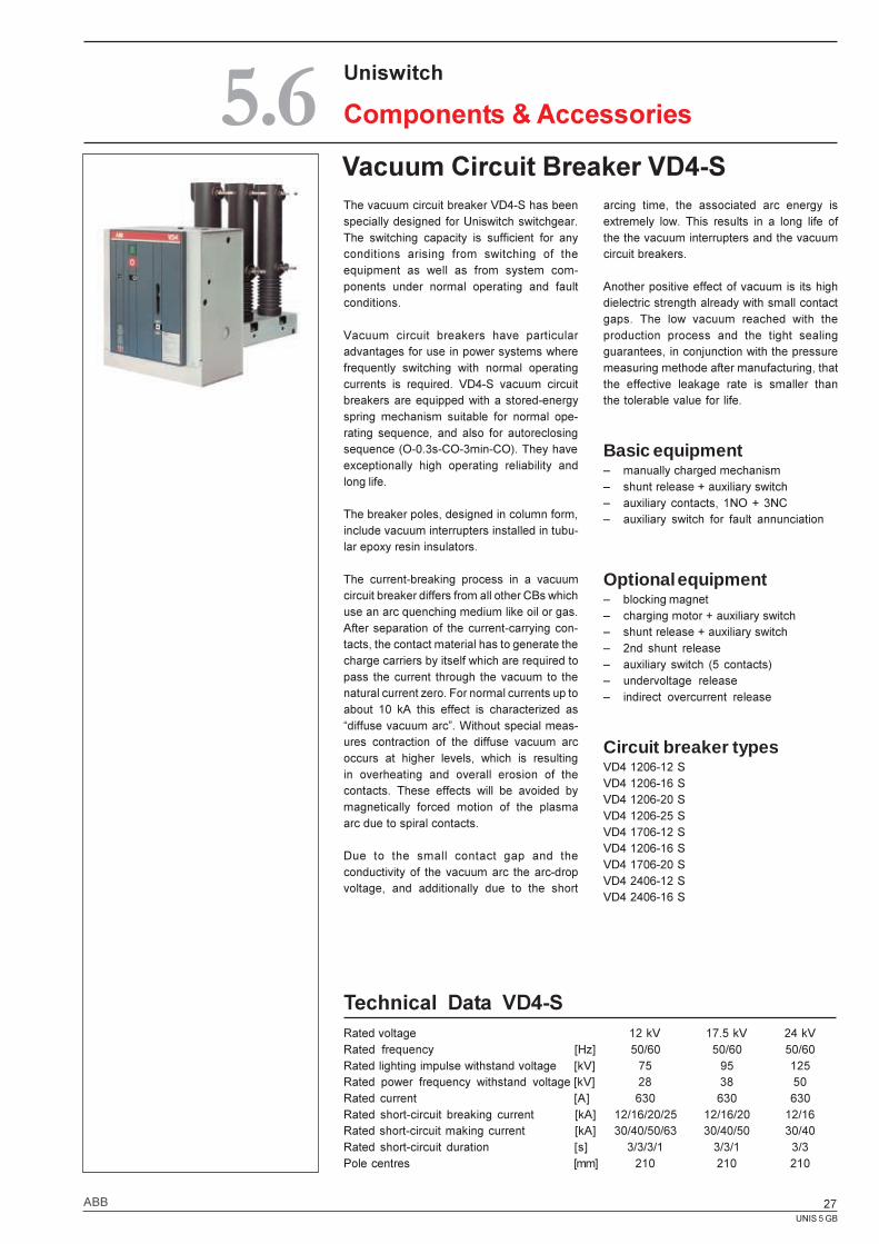
Vacuum Circuit Breaker VD4-SThe vacuum circuit breaker VD4-S has beenspecially designed for Uniswitch switchgear.The switching capacity is sufficient for anyconditions arising from switching of theequipment as well as from system com-ponents under normal operating and faultconditions.
Vacuum circuit breakers have particularadvantages for use in power systems wherefrequently switching with normal operatingcurrents is required. VD4-S vacuum circuitbreakers are equipped with a stored-energyspring mechanism suitable for normal ope-rating sequence, and also for autoreclosingsequence (O-0.3s-CO-3min-CO). They haveexceptionally high operating reliability andlong life.
The breaker poles, designed in column form,include vacuum interrupters installed in tubu-lar epoxy resin insulators.
The current-breaking process in a vacuumcircuit breaker differs from all other CBs whichuse an arc quenching medium like oil or gas.After separation of the current-carrying con-tacts, the contact material has to generate thecharge carriers by itself which are required topass the current through the vacuum to thenatural current zero. For normal currents up toabout 10 kA this effect is characterized as�diffuse vacuum arc�. Without special meas-ures contraction of the diffuse vacuum arcoccurs at higher levels, which is resultingin overheating and overall erosion of thecontacts. These effects will be avoided bymagnetically forced motion of the plasmaarc due to spiral contacts.
Due to the small contact gap and theconductivity of the vacuum arc the arc-dropvoltage, and additionally due to the short
Technical Data VD4-SRated voltage 12 kV 17.5 kV 24 kVRated frequency [Hz] 50/60 50/60 50/60Rated lighting impulse withstand voltage [kV] 75 95 125Rated power frequency withstand voltage [kV] 28 38 50Rated current [A] 630 630 630Rated short-circuit breaking current [kA] 12/16/20/25 12/16/20 12/16Rated short-circuit making current [kA] 30/40/50/63 30/40/50 30/40Rated short-circuit duration [s] 3/3/3/1 3/3/1 3/3Pole centres [mm] 210 210 210
arcing time, the associated arc energy isextremely low. This results in a long life ofthe the vacuum interrupters and the vacuumcircuit breakers.
Another positive effect of vacuum is its highdielectric strength already with small contactgaps. The low vacuum reached with theproduction process and the tight sealingguarantees, in conjunction with the pressuremeasuring methode after manufacturing, thatthe effective leakage rate is smaller thanthe tolerable value for life.
Basic equipment� manually charged mechanism� shunt release + auxiliary switch� auxiliary contacts, 1NO + 3NC� auxiliary switch for fault annunciation
Optional equipment� blocking magnet� charging motor + auxiliary switch� shunt release + auxiliary switch� 2nd shunt release� auxiliary switch (5 contacts)� undervoltage release� indirect overcurrent release
Circuit breaker typesVD4 1206-12 SVD4 1206-16 SVD4 1206-20 SVD4 1206-25 SVD4 1706-12 SVD4 1206-16 SVD4 1706-20 SVD4 2406-12 SVD4 2406-16 S
Uniswitch
Components & Accessories5.6
UNIS 5 GB
28 ABB
Uniswitch
Components & Accessories5.7
Notes1) Installation of PR521 release and relative current
sensors is not possible for circuit breaker with24 kV rated voltage.
2) Although the basic equipment is supplied asstandard, it must always be specified whenordering (see the section Compulsory acces-sories in the Esafluor HD4/S technical cata-logue) for customization.
3) With this type of circuit breaker, later additionof the pressure switch is not possible.
4) The pressure switch is always provided with twointervention thresholds. The first threshold inter-venes for low pressure and intervention is sig-nalled by contact B63 changing over (see elec-trical diagram 401738, fig. 11). The secondthreshold intervenes for insufficient pressureand intervention is signalled by the second con-tact B63 closing (see electrical diagram 401738,fig. 11). The control circuit is made by the cus-tomer. Circuit-breaker ordering codes
� The circuit-breaker selected must be com-pleted with the accessories specified in thestandard fittings (see Kits B and C on page 12of the HD4/R circuit-breaker catalogue; theoptional accessories are indicated on page 14of the HD4/R catalogue).
� Should the pressure switch accessory be re-quired, specify the request at the time of or-dering the circuit-breaker as subsequent appli-cation is not possible by the customer.
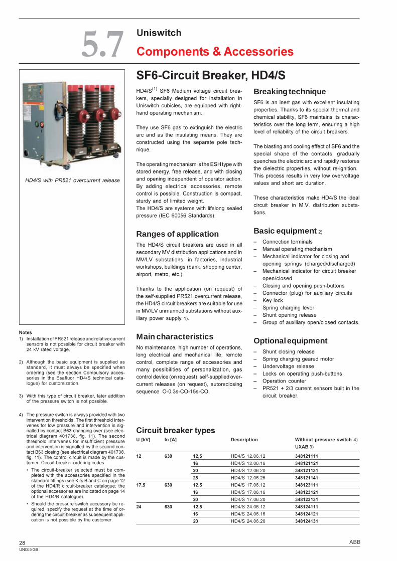
SF6-Circuit Breaker, HD4/SBreaking techniqueSF6 is an inert gas with excellent insulatingproperties. Thanks to its special thermal andchemical stability, SF6 maintains its charac-teristics over the long term, ensuring a highlevel of reliability of the circuit breakers.
The blasting and cooling effect of SF6 and thespecial shape of the contacts, graduallyquenches the electric arc and rapidly restoresthe dielectric properties, without re-ignition.This process results in very low overvoltagevalues and short arc duration.
These characteristics make HD4/S the idealcircuit breaker in M.V. distribution substa-tions.
Basic equipment 2)
� Connection terminals� Manual operating mechanism� Mechanical indicator for closing and
opening springs (charged/discharged)� Mechanical indicator for circuit breaker
open/closed� Closing and opening push-buttons� Connector (plug) for auxiliary circuits� Key lock� Spring charging lever� Shunt opening release� Group of auxiliary open/closed contacts.
Optional equipment� Shunt closing release� Spring charging geared motor� Undervoltage release� Locks on operating push-buttons� Operation counter� PR521 + 2/3 current sensors built in the
circuit breaker.
Circuit breaker typesU [kV] In [A] Description Without pressure switch 4)
UXAB 3)
12 630 12,5 HD4/S 12.06.12 348121111
16 HD4/S 12.06.16 348121121
20 HD4/S 12.06.20 348121131
25 HD4/S 12.06.25 348121141
17,5 630 12,5 HD4/S 17.06.12 348123111
16 HD4/S 17.06.16 348123121
20 HD4/S 17.06.20 348123131
24 630 12,5 HD4/S 24.06.12 348124111
16 HD4/S 24.06.16 348124121
20 HD4/S 24.06.20 348124131
HD4/S(1) SF6 Medium voltage circuit brea-kers, specially designed for installation inUniswitch cubicles, are equipped with right-hand operating mechanism.
They use SF6 gas to extinguish the electricarc and as the insulating means. They areconstructed using the separate pole tech-nique.
The operating mechanism is the ESH type withstored energy, free release, and with closingand opening independent of operator action.By adding electrical accessories, remotecontrol is possible. Construction is compact,sturdy and of limited weight.The HD4/S are systems with lifelong sealedpressure (IEC 60056 Standards).
Ranges of applicationThe HD4/S circuit breakers are used in allsecondary MV distribution applications and inMV/LV substations, in factories, industrialworkshops, buildings (bank, shopping center,airport, metro, etc.).
Thanks to the application (on request) ofthe self-supplied PR521 overcurrent release,the HD4/S circuit breakers are suitable for usein MV/LV unmanned substations without aux-iliary power supply 1).
Main characteristicsNo maintenance, high number of operations,long electrical and mechanical life, remotecontrol, complete range of accessories andmany possibilities of personalization, gascontrol device (on request), self-supplied over-current releases (on request), autoreclosingsequence O-0,3s-CO-15s-CO.
HD4/S with PR521 overcurrent release
UNIS 5 GB
29ABB
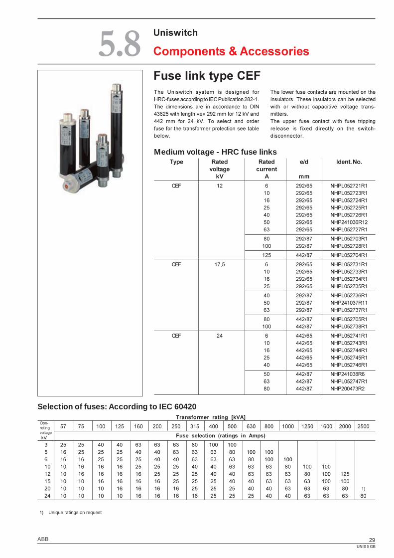
Fuse link type CEFThe Uniswitch system is designed forHRC-fuses according to IEC Publication 282-1.The dimensions are in accordance to DIN43625 with length «e» 292 mm for 12 kV and442 mm for 24 kV. To select and orderfuse for the transformer protection see tablebelow.
The lower fuse contacts are mounted on theinsulators. These insulators can be selectedwith or without capacitive voltage trans-mitters.The upper fuse contact with fuse trippingrelease is fixed directly on the switch-disconnector.
Medium voltage - HRC fuse links
Selection of fuses: According to IEC 60420
Uniswitch
Components & Accessories5.8
1) Unique ratings on request
Type Rated Rated e/d Ident. No.voltage current
kV A mm
CEF 12 6 292/65 NHPL052721R110 292/65 NHPL052723R116 292/65 NHPL052724R125 292/65 NHPL052725R140 292/65 NHPL052726R150 292/65 NHP241036R1263 292/65 NHPL052727R1
80 292/87 NHPL052703R1100 292/87 NHPL052728R1
125 442/87 NHPL052704R1
CEF 17,5 6 292/65 NHPL052731R110 292/65 NHPL052733R116 292/65 NHPL052734R125 292/65 NHPL052735R1
40 292/87 NHPL052736R150 292/87 NHP241037R1163 292/87 NHPL052737R1
80 442/87 NHPL052705R1100 442/87 NHPL052738R1
CEF 24 6 442/65 NHPL052741R110 442/65 NHPL052743R116 442/65 NHPL052744R125 442/65 NHPL052745R140 442/65 NHPL052746R1
50 442/87 NHP241038R663 442/87 NHPL052747R180 442/87 NHP200473R2
Transformer rating [kVA]
57 75 100 125 160 200 250 315 400 500 630 800 1000 1250 1600 2000 2500
Fuse selection (ratings in Amps)
3 25 25 40 40 63 63 63 80 100 1005 16 25 25 25 40 40 63 63 63 80 100 1006 16 16 25 25 25 40 40 63 63 63 80 100 10010 10 16 16 16 25 25 25 40 40 63 63 63 80 100 10012 10 16 16 16 16 25 25 25 40 40 63 63 63 80 100 12515 10 10 16 16 16 16 25 25 25 40 40 63 63 63 100 10020 10 10 10 16 16 16 16 25 25 25 40 40 63 63 63 80 1)
24 10 10 10 10 16 16 16 16 25 25 25 40 40 63 63 63 80
Ope-ratingvoltage kV
UNIS 5 GB
30 ABB
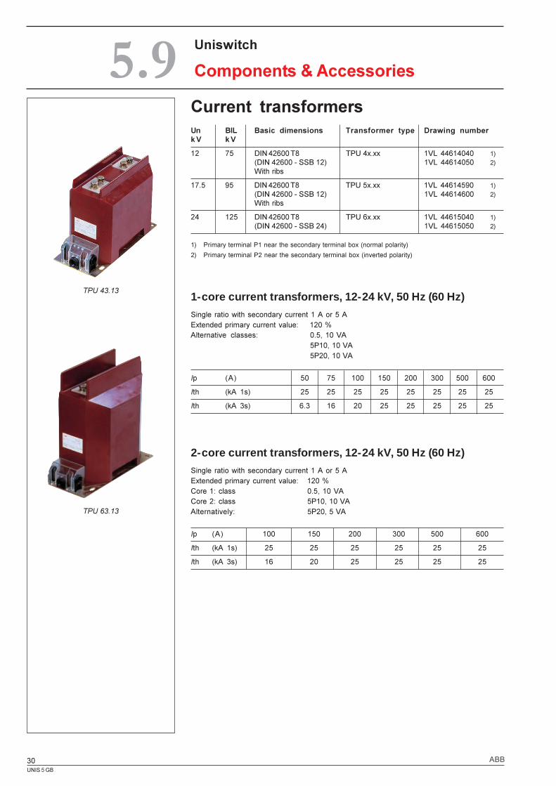
2-core current transformers, 12-24 kV, 50 Hz (60 Hz)Single ratio with secondary current 1 A or 5 AExtended primary current value: 120 %Core 1: class 0.5, 10 VACore 2: class 5P10, 10 VAAlternatively: 5P20, 5 VA
Ip (A) 100 150 200 300 500 600
Ith (kA 1s) 25 25 25 25 25 25
Ith (kA 3s) 16 20 25 25 25 25
1) Primary terminal P1 near the secondary terminal box (normal polarity)
2) Primary terminal P2 near the secondary terminal box (inverted polarity)
1-core current transformers, 12-24 kV, 50 Hz (60 Hz)Single ratio with secondary current 1 A or 5 AExtended primary current value: 120 %Alternative classes: 0.5, 10 VA
5P10, 10 VA5P20, 10 VA
Ip (A) 50 75 100 150 200 300 500 600
Ith (kA 1s) 25 25 25 25 25 25 25 25
Ith (kA 3s) 6.3 16 20 25 25 25 25 25
Uniswitch
Components & Accessories5.9Current transformersUn BIL Basic dimensions Transformer type Drawing numberk V k V
12 75 DIN 42600 T8 TPU 4x.xx 1VL 44614040 1)(DIN 42600 - SSB 12) 1VL 44614050 2)With ribs
17.5 95 DIN 42600 T8 TPU 5x.xx 1VL 44614590 1)(DIN 42600 - SSB 12) 1VL 44614600 2)With ribs
24 125 DIN 42600 T8 TPU 6x.xx 1VL 44615040 1)(DIN 42600 - SSB 24) 1VL 44615050 2)
TPU 43.13
TPU 63.13
UNIS 5 GB
31ABB
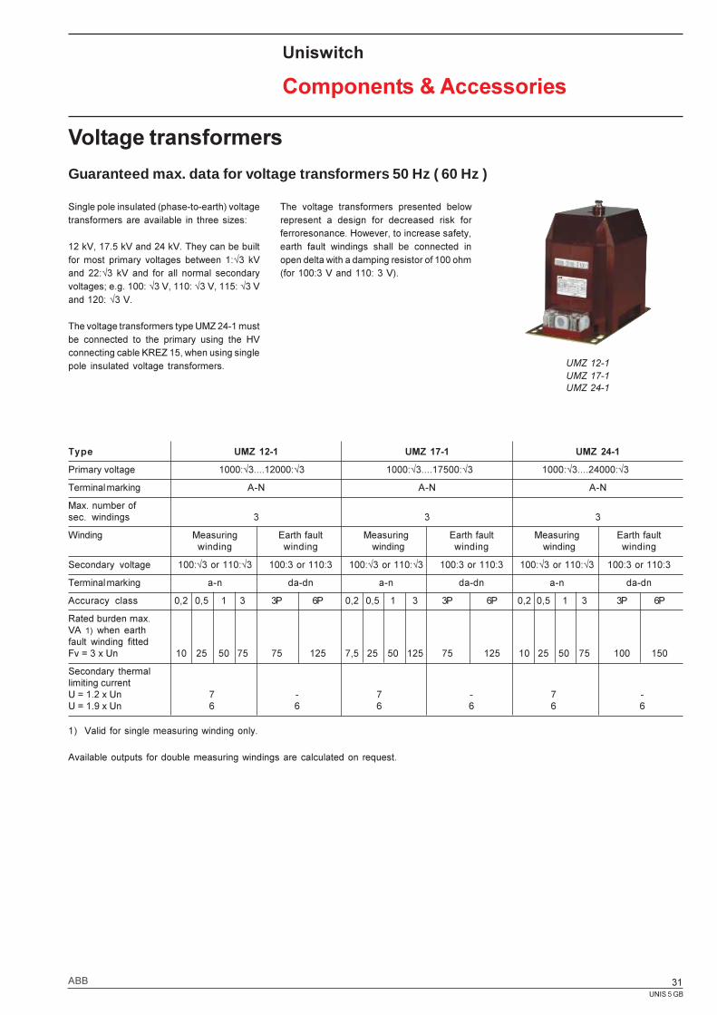
Type UMZ 12-1 UMZ 17-1 UMZ 24-1
Primary voltage 1000:Ö3....12000:Ö3 1000:Ö3....17500:Ö3 1000:Ö3....24000:Ö3
Terminal marking A-N A-N A-N
Max. number ofsec. windings 3 3 3
Winding Measuring Earth fault Measuring Earth fault Measuring Earth faultwinding winding winding winding winding winding
Secondary voltage 100:Ö3 or 110:Ö3 100:3 or 110:3 100:Ö3 or 110:Ö3 100:3 or 110:3 100:Ö3 or 110:Ö3 100:3 or 110:3
Terminal marking a-n da-dn a-n da-dn a-n da-dn
Accuracy class 0,2 0,5 1 3 3P 6P 0,2 0,5 1 3 3P 6P 0,2 0,5 1 3 3P 6P
Rated burden max.VA 1) when earthfault winding fittedFv = 3 x Un 10 25 50 75 75 125 7,5 25 50 125 75 125 10 25 50 75 100 150
Secondary thermallimiting currentU = 1.2 x Un 7 - 7 - 7 -U = 1.9 x Un 6 6 6 6 6 6
Voltage transformers
Guaranteed max. data for voltage transformers 50 Hz ( 60 Hz )
Uniswitch
Components & Accessories
Single pole insulated (phase-to-earth) voltagetransformers are available in three sizes:
12 kV, 17.5 kV and 24 kV. They can be builtfor most primary voltages between 1:Ö3 kVand 22:Ö3 kV and for all normal secondaryvoltages; e.g. 100: Ö3 V, 110: Ö3 V, 115: Ö3 Vand 120: Ö3 V.
The voltage transformers type UMZ 24-1 mustbe connected to the primary using the HVconnecting cable KREZ 15, when using singlepole insulated voltage transformers.
1) Valid for single measuring winding only.
Available outputs for double measuring windings are calculated on request.
The voltage transformers presented belowrepresent a design for decreased risk forferroresonance. However, to increase safety,earth fault windings shall be connected inopen delta with a damping resistor of 100 ohm(for 100:3 V and 110: 3 V).
UMZ 12-1UMZ 17-1UMZ 24-1
UNIS 5 GB
32 ABB
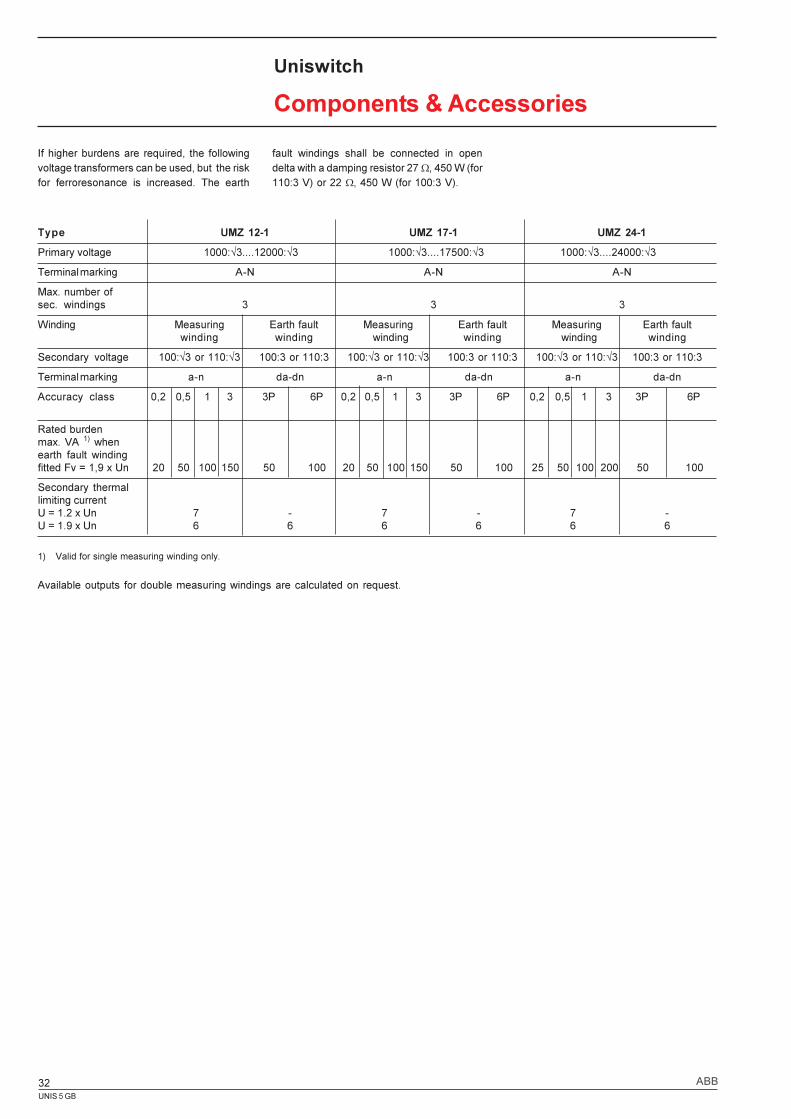
Type UMZ 12-1 UMZ 17-1 UMZ 24-1
Primary voltage 1000:Ö3....12000:Ö3 1000:Ö3....17500:Ö3 1000:Ö3....24000:Ö3
Terminal marking A-N A-N A-N
Max. number ofsec. windings 3 3 3
Winding Measuring Earth fault Measuring Earth fault Measuring Earth faultwinding winding winding winding winding winding
Secondary voltage 100:Ö3 or 110:Ö3 100:3 or 110:3 100:Ö3 or 110:Ö3 100:3 or 110:3 100:Ö3 or 110:Ö3 100:3 or 110:3
Terminal marking a-n da-dn a-n da-dn a-n da-dn
Accuracy class 0,2 0,5 1 3 3P 6P 0,2 0,5 1 3 3P 6P 0,2 0,5 1 3 3P 6P
Rated burdenmax. VA 1) whenearth fault windingfitted Fv = 1,9 x Un 20 50 100 150 50 100 20 50 100 150 50 100 25 50 100 200 50 100
Secondary thermallimiting currentU = 1.2 x Un 7 - 7 - 7 -U = 1.9 x Un 6 6 6 6 6 6
Uniswitch
Components & Accessories
1) Valid for single measuring winding only.
Available outputs for double measuring windings are calculated on request.
If higher burdens are required, the followingvoltage transformers can be used, but the riskfor ferroresonance is increased. The earth
fault windings shall be connected in opendelta with a damping resistor 27 W, 450 W (for110:3 V) or 22 W, 450 W (for 100:3 V).
UNIS 5 GB
33ABB
Uniswitch
Components & Accessories
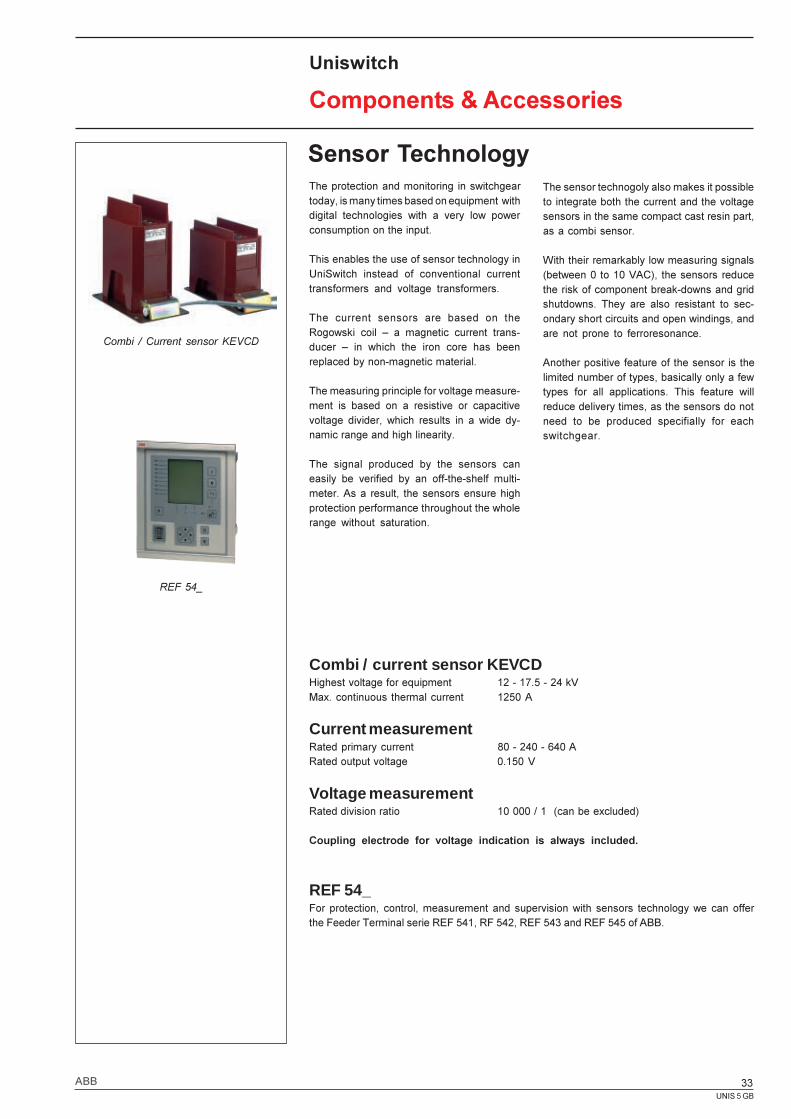
Sensor TechnologyThe protection and monitoring in switchgeartoday, is many times based on equipment withdigital technologies with a very low powerconsumption on the input.
This enables the use of sensor technology inUniSwitch instead of conventional currenttransformers and voltage transformers.
The current sensors are based on theRogowski coil � a magnetic current trans-ducer � in which the iron core has beenreplaced by non-magnetic material.
The measuring principle for voltage measure-ment is based on a resistive or capacitivevoltage divider, which results in a wide dy-namic range and high linearity.
The signal produced by the sensors caneasily be verified by an off-the-shelf multi-meter. As a result, the sensors ensure highprotection performance throughout the wholerange without saturation.
Combi / current sensor KEVCDHighest voltage for equipment 12 - 17.5 - 24 kVMax. continuous thermal current 1250 A
Current measurementRated primary current 80 - 240 - 640 ARated output voltage 0.150 V
Voltage measurementRated division ratio 10 000 / 1 (can be excluded)
Coupling electrode for voltage indication is always included.
REF 54_For protection, control, measurement and supervision with sensors technology we can offerthe Feeder Terminal serie REF 541, RF 542, REF 543 and REF 545 of ABB.
Combi / Current sensor KEVCD
REF 54_
The sensor technogoly also makes it possibleto integrate both the current and the voltagesensors in the same compact cast resin part,as a combi sensor.
With their remarkably low measuring signals(between 0 to 10 VAC), the sensors reducethe risk of component break-downs and gridshutdowns. They are also resistant to sec-ondary short circuits and open windings, andare not prone to ferroresonance.
Another positive feature of the sensor is thelimited number of types, basically only a fewtypes for all applications. This feature willreduce delivery times, as the sensors do notneed to be produced specifially for eachswitchgear.
UNIS 5 GB
34 ABB
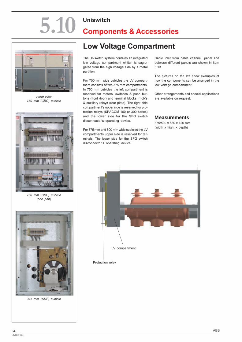
Low Voltage CompartmentThe Uniswitch system contains an integratedlow voltage compartment whitch is segre-gated from the high voltage side by a metalpartition.
For 750 mm wide cubicles the LV compart-ment consists of two 375 mm compartments.In 750 mm cubicles the left compartment isreserved for meters, switches & push but-tons (front door) and terminal blocks, mcb´s& auxiliary relays (rear plate). The right sidecompartment's upper side is reserved for pro-tection relays (SPACOM 100 or 300 series)and the lower side for the SFG switchdisconnector's operating device.
For 375 mm and 500 mm wide cubicles the LVcompartments upper side is reserved for ter-minals. The lower side for the SFG switchdisconnector´s operating device.
Uniswitch
Components & Accessories5.10
Front view750 mm (CBC) cubicle
750 mm (CBC) cubicle(one part)
375 mm (SDF) cubicle
Cable inlet from cable channel, panel andbetween different panels are shown in item5.13.
The pictures on the left show examples ofhow the components can be arranged in thelow voltage compartment.
Other arrangements and special applicationsare available on request.
Protection relay
LV compartment
Measurements375/500 x 580 x 120 mm(width x hight x depth)
UNIS 5 GB
35ABB
Uniswitch
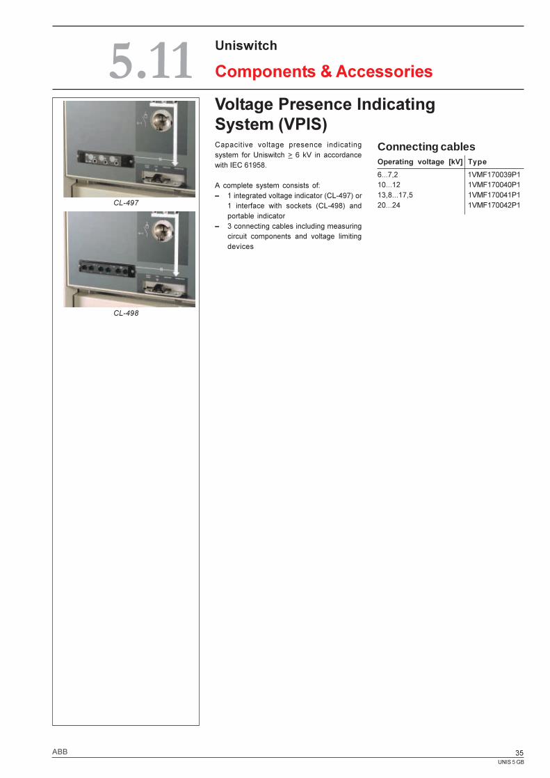
Components & Accessories5.11Voltage Presence IndicatingSystem (VPIS)Capacitive voltage presence indicatingsystem for Uniswitch > 6 kV in accordancewith IEC 61958.
A complete system consists of:� 1 integrated voltage indicator (CL-497) or
1 interface with sockets (CL-498) andportable indicator
� 3 connecting cables including measuringcircuit components and voltage limitingdevices
CL-497
CL-498
Connecting cablesOperating voltage [kV] Type
6...7,2 1VMF170039P110...12 1VMF170040P113,8...17,5 1VMF170041P120...24 1VMF170042P1
UNIS 5 GB
36 ABB
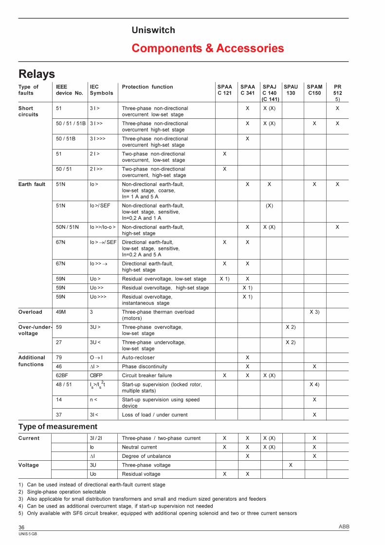
Current 3I / 2I Three-phase / two-phase current X X X (X) X
Io Neutral current X X X (X) X
DI Degree of unbalance X X
Voltage 3U Three-phase voltage X
Uo Residual voltage X X
Type of IEEE IEC Protection function SPAA SPAA SPAJ SPAU SPAM PRfaults device No. Symbols C 121 C 341 C 140 130 C150 512
(C 141) 5)
Short 51 3 I > Three-phase non-directional X X (X) Xcircuits overcurrent low-set stage
50 / 51 / 51B 3 I >> Three-phase non-directional X X (X) X Xovercurrent high-set stage
50 / 51B 3 I >>> Three-phase non-directional Xovercurrent high-set stage
51 2 I > Two-phase non-directional Xovercurrent, low-set stage
50 / 51 2 I >> Two-phase non-directional Xovercurrent, high-set stage
Earth fault 51N Io > Non-directional earth-fault, X X X Xlow-set stage, coarse,In= 1 A and 5 A
51N Io >/ SEF Non-directional earth-fault, (X)low-set stage, sensitive,In=0,2 A and 1 A
50N / 51N Io >>/Io-o > Non-directional earth-fault, X X (X) Xhigh-set stage
67N Io > ®/ SEF Directional earth-fault, X Xlow-set stage, sensitive,In=0,2 A and 5 A
67N Io >> ® Directional earth-fault, X Xhigh-set stage
59N Uo > Residual overvoltage, low-set stage X 1) X
59N Uo >> Residual overvoltage, high-set stage X 1)
59N Uo >>> Residual overvoltage, X 1)instantaneous stage
Overload 49M 3 Three-phase therman overload X 3)(motors)
Over-/under- 59 3U > Three-phase overvoltage, X 2)voltage low-set stage
27 3U < Three-phase undervoltage, X 2)low-set stage
Additional 79 O ® I Auto-recloser X
46 DI > Phase discontinuity X X
62BF CBFP Circuit breaker failure X X X (X)
48 / 51 Is>/I
s2t Start-up supervision (locked rotor, X 4)
multiple starts)
14 n < Start-up supervision using speed Xdevice
37 3I < Loss of load / under current X
Relays
Uniswitch
Components & Accessories
Type of measurement
1) Can be used instead of directional earth-fault current stage2) Single-phase operation selectable3) Also applicable for small distribution transformers and small and medium sized generators and feeders4) Can be used as additional overcurrent stage, if start-up supervision not needed5) Only available with SF6 circuit breaker, equipped with additional opening solenoid and two or three current sensors
functions
UNIS 5 GB
37ABB
Uniswitch
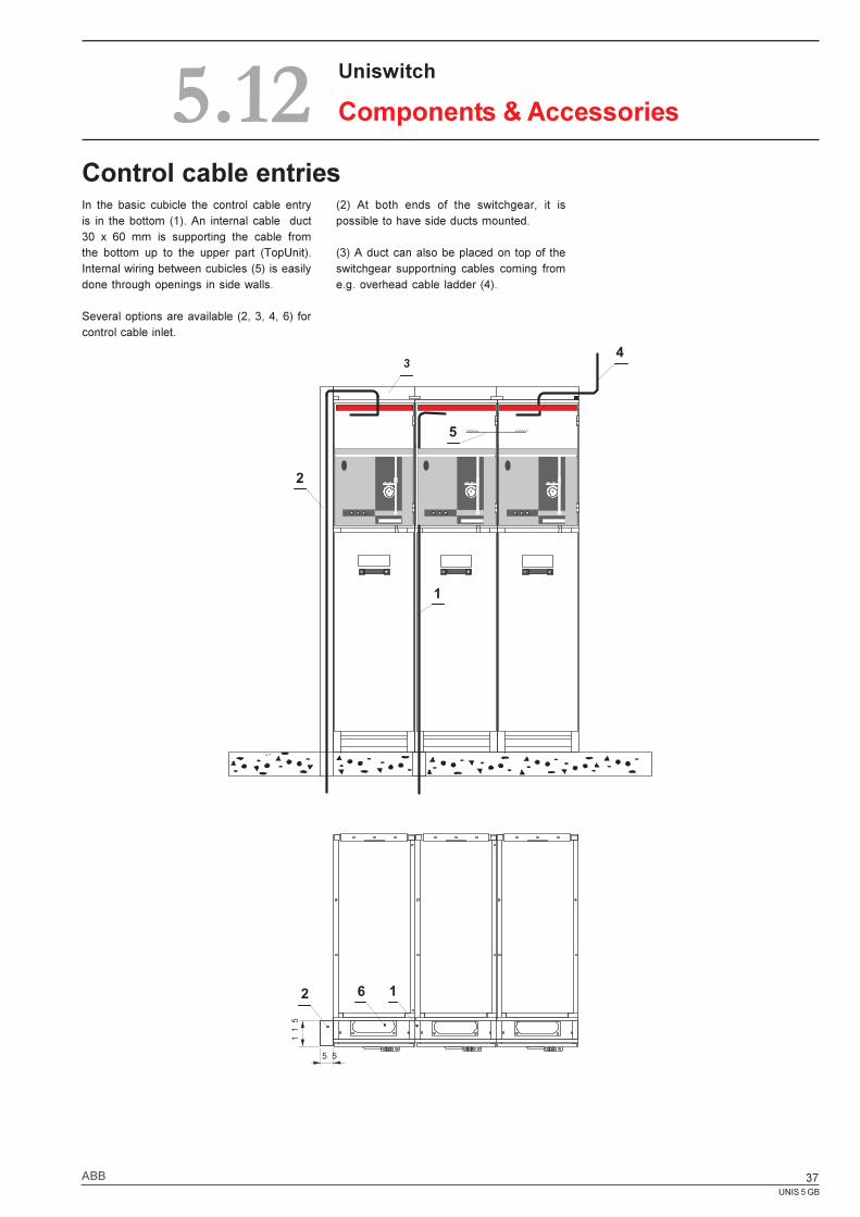
Components & Accessories5.12Control cable entriesIn the basic cubicle the control cable entryis in the bottom (1). An internal cable duct30 x 60 mm is supporting the cable fromthe bottom up to the upper part (TopUnit).Internal wiring between cubicles (5) is easilydone through openings in side walls.
Several options are available (2, 3, 4, 6) forcontrol cable inlet.
(2) At both ends of the switchgear, it ispossible to have side ducts mounted.
(3) A duct can also be placed on top of theswitchgear supportning cables coming frome.g. overhead cable ladder (4).
. .
5
43
2
1
2 6 1
5 5
115
UNIS 5 GB
38 ABB
Uniswitch
Components & Accessories5.13Arc gas channel
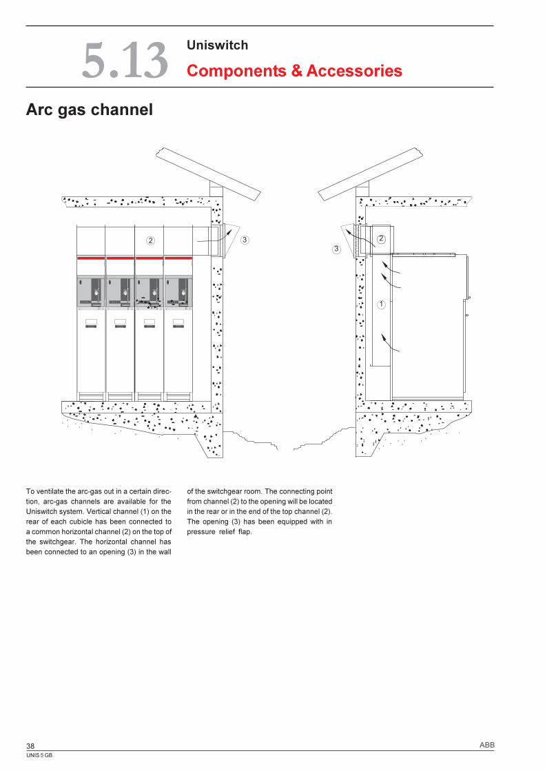
To ventilate the arc-gas out in a certain direc-tion, arc-gas channels are available for theUniswitch system. Vertical channel (1) on therear of each cubicle has been connected toa common horizontal channel (2) on the top ofthe switchgear. The horizontal channel hasbeen connected to an opening (3) in the wall
of the switchgear room. The connecting pointfrom channel (2) to the opening will be locatedin the rear or in the end of the top channel (2).The opening (3) has been equipped with inpressure relief flap.
3
2
1
32
UNIS 5 GB
39ABB
6.1 Cubicle dimensions ........................... 40
6.2 Floor plan........................................... 41
6.3 Cable arrangement ............................ 42
6.4 Technical data / Dimensions.............. 44
Uniswitch
Technical data / Dimensions6.
UNIS 5 GB
40 ABB
Cubicle dimensions
Uniswitch
Technical data / Dimensions6.1
Cubicle types:SDCSDFDBCBRCSECBMC
Cubicle types:CBCSMCSBC
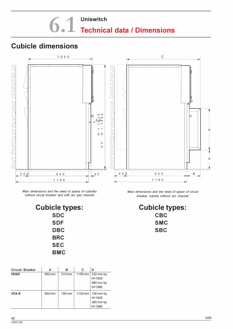
Main dimensions and the need of space of circuitbreaker cubicle without arc channel
Main dimensions and the need of space of cubicleswithout circuit breaker and with arc gas channel
Circuit Breaker A B C DHD4/S 652 mm 215 mm 1155 mm 230 mm by
H=1635480 mm byH=1885
VD4-S 652 mm 195 mm 1135 mm 130 mm byH=1635380 mm byH=1885
9 4 0
H = 1635
Alt H = 1885
4 0
3 5
1 0 0 0
2 5 0
1 1 9 0
9 4 0 B
C
2 5 0
1 1 9 0
A
D
UNIS 5 GB
41ABB
Uniswitch
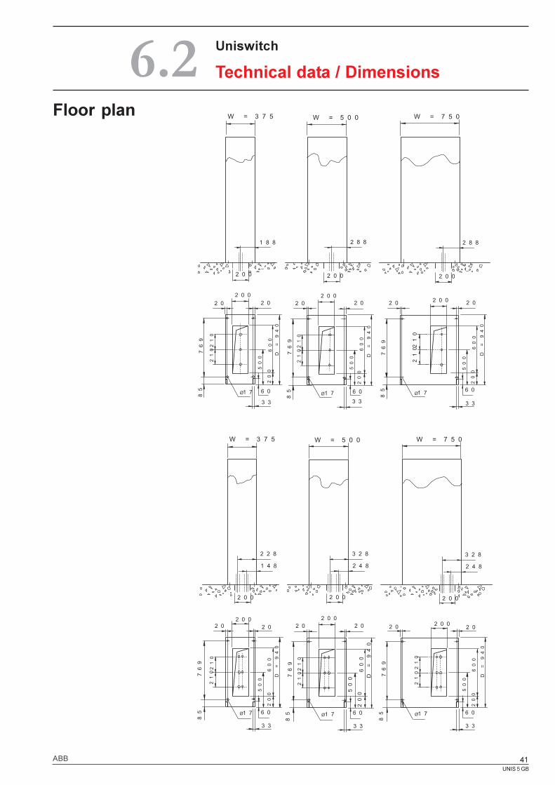
Technical data / Dimensions6.2Floor plan
2 0 0
1 8 8
2 0 0
210
2 0 0
2 0
500
769
85 1 7Ø
D = 940
W = 3 7 5 W = 5 0 0 W = 7 5 0
2 8 8
2 0 0
2 8 8
2 0 0
2 0
210
600
200
6 0
2 0 02 02 0
769
85
210
Ø 1 7
500
D = 940
600
200
6 0
210
3 3
2 0
769
85
2 0 0
3 3
2 0
500
D = 940
600
200
6 0
3 3
Ø 1 7
W = 3 7 5 W = 5 0 0 W = 7 5 0
2 2 8
1 4 8
2 0 0
3 2 8
2 4 8
2 0 0
3 2 8
2 4 8
210
2 0 02 0
500
769
85 1 7Ø
D = 940
2 0
210
600
200
6 0
2 0 02 02 0
210
769
85
210
Ø 1 7
500
D = 940
600
200
6 0
210
3 3
2 0
769
85
2 0 0
3 3
2 0
500
D = 940
600
200
6 0
3 3
Ø 1 7
210
210
210
UNIS 5 GB
42 ABB
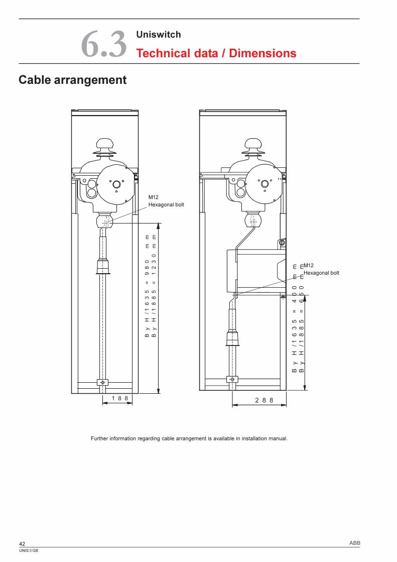
Cable arrangement
Uniswitch
Technical data / Dimensions6.3
Further information regarding cable arrangement is available in installation manual.
1 8 8
By H/1635 = 980 mm
By H/1885 = 1230 mm
2 8 8
By H/1635 = 400 mm
By H/1885 = 650 mm
M12Hexagonal bolt
M12Hexagonal bolt
UNIS 5 GB
43ABB
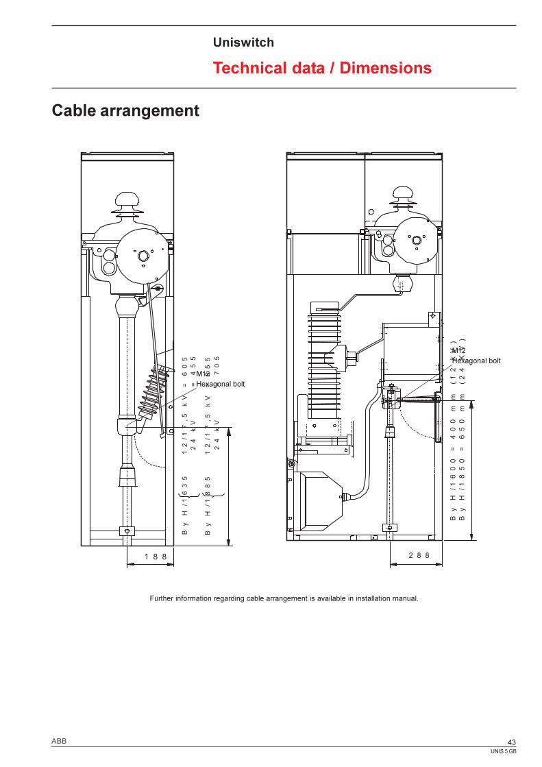
Cable arrangement
Uniswitch
Technical data / Dimensions
Further information regarding cable arrangement is available in installation manual.
1 8 8
By H/1635 12/17,5 kV = 605
24 kV = 455
By H/1885 12/17,5 kV = 855
24 kV = 705
2 8 8
By H/1600 = 400 mm (12 kV)
By H/1850 = 650 mm (24 KV)
M12Hexagonal bolt
M12Hexagonal bolt
UNIS 5 GB
44 ABB
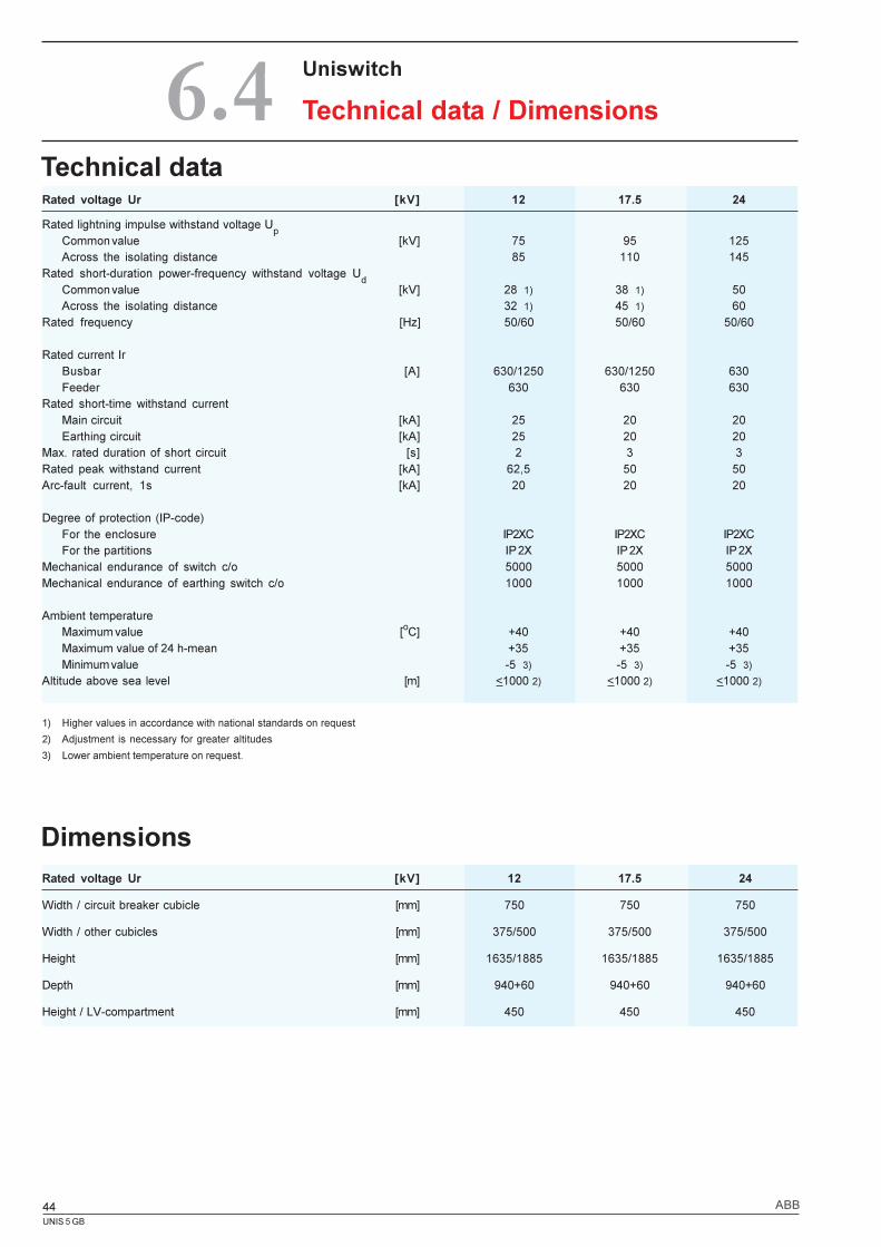
Rated voltage Ur [kV] 12 17.5 24
Width / circuit breaker cubicle [mm] 750 750 750
Width / other cubicles [mm] 375/500 375/500 375/500
Height [mm] 1635/1885 1635/1885 1635/1885
Depth [mm] 940+60 940+60 940+60
Height / LV-compartment [mm] 450 450 450
Dimensions
Technical data
Uniswitch
Technical data / Dimensions6.4
1) Higher values in accordance with national standards on request
2) Adjustment is necessary for greater altitudes
3) Lower ambient temperature on request.
Rated voltage Ur [kV] 12 17.5 24
Rated lightning impulse withstand voltage Up
Common value [kV] 75 95 125Across the isolating distance 85 110 145
Rated short-duration power-frequency withstand voltage Ud
Common value [kV] 28 1) 38 1) 50Across the isolating distance 32 1) 45 1) 60
Rated frequency [Hz] 50/60 50/60 50/60
Rated current IrBusbar [A] 630/1250 630/1250 630Feeder 630 630 630
Rated short-time withstand currentMain circuit [kA] 25 20 20Earthing circuit [kA] 25 20 20
Max. rated duration of short circuit [s] 2 3 3Rated peak withstand current [kA] 62,5 50 50Arc-fault current, 1s [kA] 20 20 20
Degree of protection (IP-code)For the enclosure IP2XC IP2XC IP2XCFor the partitions IP 2X IP 2X IP 2X
Mechanical endurance of switch c/o 5000 5000 5000Mechanical endurance of earthing switch c/o 1000 1000 1000
Ambient temperatureMaximum value [oC] +40 +40 +40Maximum value of 24 h-mean +35 +35 +35Minimum value -5 3) -5 3) -5 3)
Altitude above sea level [m] <1000 2) <1000 2) <1000 2)
UNIS 5 GB
45ABB
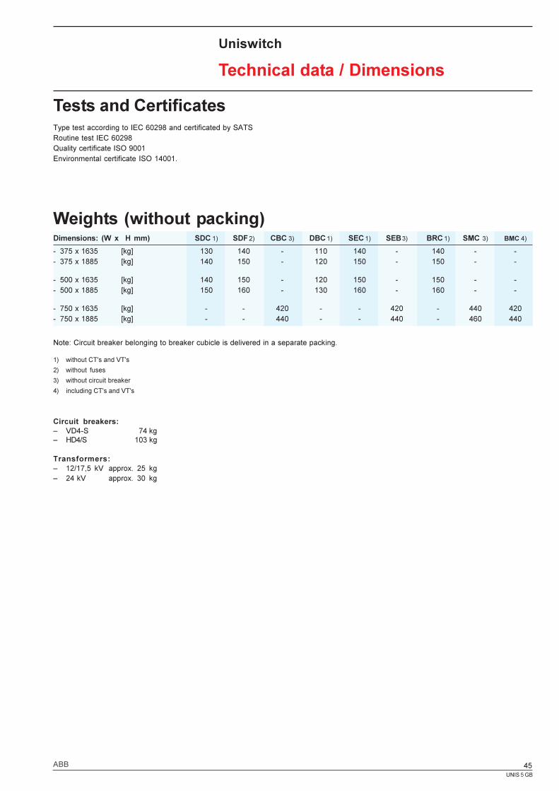
Weights (without packing)
Tests and CertificatesType test according to IEC 60298 and certificated by SATSRoutine test IEC 60298Quality certificate ISO 9001Environmental certificate ISO 14001.
Uniswitch
Technical data / Dimensions
Note: Circuit breaker belonging to breaker cubicle is delivered in a separate packing.
1) without CT's and VT's
2) without fuses
3) without circuit breaker
4) including CT's and VT's
Circuit breakers:� VD4-S 74 kg� HD4/S 103 kg
Transformers:� 12/17,5 kV approx. 25 kg� 24 kV approx. 30 kg
Dimensions: (W x H mm) SDC 1) SDF 2) CBC 3) DBC 1) SEC 1) SEB 3) BRC 1) SMC 3) BMC 4)
- 375 x 1635 [kg] 130 140 - 110 140 - 140 - -- 375 x 1885 [kg] 140 150 - 120 150 - 150 - -
- 500 x 1635 [kg] 140 150 - 120 150 - 150 - -- 500 x 1885 [kg] 150 160 - 130 160 - 160 - -
- 750 x 1635 [kg] - - 420 - - 420 - 440 420- 750 x 1885 [kg] - - 440 - - 440 - 460 440
UNIS 5 GB
46 ABB
Uniswitch
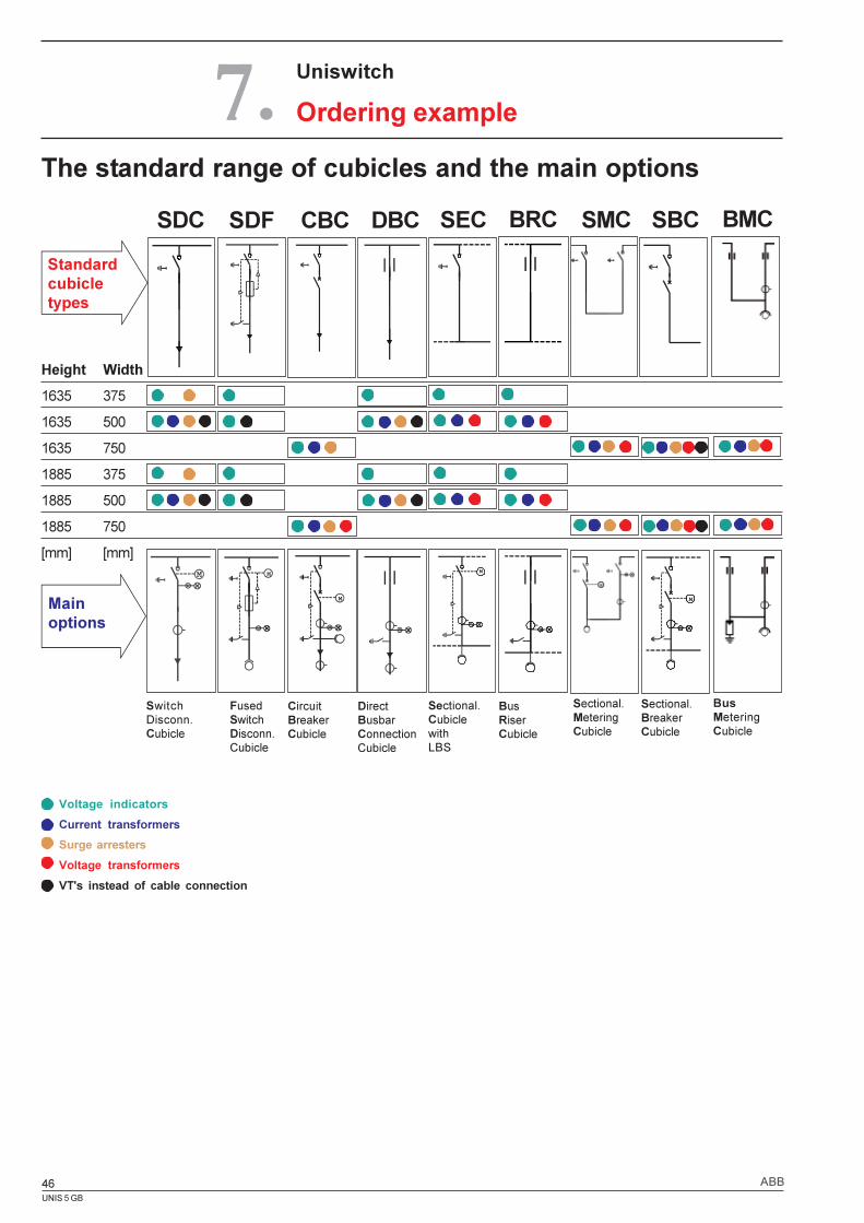
Ordering example7.
Mainoptions
Standardcubicletypes
Voltage indicators
Current transformers
Surge arresters
Voltage transformers
VT's instead of cable connection
Height Width
1635 375
1635 500
1635 750
1885 375
1885 500
1885 750
[mm] [mm]
FusedSwitchDisconn.Cubicle
The standard range of cubicles and the main options
SEC
SwitchDisconn.Cubicle
SDC SDF
CircuitBreakerCubicle
CBC
DirectBusbarConnectionCubicle
DBC
Sectional.CubiclewithLBS
BusRiserCubicle
BRC SMC
Sectional.MeteringCubicle
SBC
Sectional.BreakerCubicle
BMC
BusMeteringCubicle

UNIS 5 GB
47ABB
UNIS 5 GB
48 ABB
Information given in this publication isgenerally applicable to equipmentdescribed. Changes may be made in futurewithout notice.
Waa
sa G
raph
ics
Oy,
150
0
ABB OyMedium Voltage TechnologyP.O. Box 613, FIN-65101 Vaasa, FinlandPhone: +358 10 22 11Fax: +358 10 22 44661www.abb.com
UN
IS 5
GB
02-0
4