abc
DESCRIPTION
SPECIFICATIONTRANSCRIPT

HARYANA VIDYUT PRASARAN NIGAM LIMITED
BIDDING DOCUMENT NO. WB/2008/G-10
(PACKAGE-A )
TECHNICAL SPECIFICATION
OF 132KV LINES WITH
ACSR PANTHER CONDUCTOR
(VOL-II Part-A)
Chief Engineer/MM,
Haryana Vidyut Prasaran Nigam Limited Shakti Bhawan, sector-6
Panchkula-134109 Ph: 0172-2583724

SECTION-VI
TECHNICAL SPECIFICATION
CONTENTS PART-I TECHNICAL SPECIFICATION FOR TOWERS PART-II TECHNICAL SPECIFICATION FOR LINE MATERIAL PART-III TECHNICAL DATA/INFORMATION TO BE SUBMTTED
WITH THE BID

SECTION-VI
PART-I

SECTION-VI
(PART-I) TECHNICAL SPECIFICATION CONTENTS
Clause No. Description Page No.
1.1 GENERAL INFORMATION AND SCOPE 1 1.2 DETAIL OF TRANSMISSION LINE ROUTES AND 3
TERRAIN 1.3 RESULTS OF SURVEYS 4 1.4 ACCESS TO THE LINE AND RIGHT OF WAY 4 1.5 DETAILED SURVEY, OPTIMISATION OF TOWER 4
LOCATION 1.6 ENVIRONMENTAL CONDITIONS 9 1.7 TECHNICAL DATA 9 1.8 STATUTORY REGULATIONS AN STANDARDS 9 1.9 QUALITY ASSURANCE, INSPECION AN TESTING 10 1.10 TECHNICAL PARAMETERS OF 132 KV LINE 11 2.0 DETAIL OF LINE MATERIAL FOR 132 KV LINE 12 2.1 PARTICULAR OF CONDUCTOR AND EARTHWIRE 13 2.2 PARTICULAR OF INSULATOR STRING WITH 13 STANDARD DISC INSULATIORS 2.3 INSULATOR STRING HARDWARE 13 2.4 ACCESSORIES FOR CONDUCTOR AND 14
EARTHWIRE 3.0 TRANSMISSION TOWERS 14 3.1 GENERAL DESCRIPTION OF THE TOWER 14 3.2 TYPE OF TOWER 14 3.3 SPANS AND CLEARANCES 15 3.4 MAXIMUM TENSION 16 3.5 MATERIALS 17 3.6 TOWER ACCESSORIES 18 3.7 TOWR FABRICALTION 20 3.8 GALVANISING 21 3.9 EARTHING 22 3.10 INSPECTION AND TESTS 22 3.11 TESTING SOF TOWERS 26 3.12 STANDARDS 29 4.0 TOWER FOUNDATION 32 4.3 TYPEOF SOIL 4.4 FOUNDATION TYPES 32 4.6 PROPERTIES OF CONCRETE & REINFORCEMENT33 4.7 UNIT RATES AND MEASUREMENT 35 4.8 CONSTRUCTION OF TOWER FOUNDATIONS 36 4.9 SETTING OF STUBS 36 4.10 STUB SETTING TEMPLATES 37 4.11 MIXING, PLACING AND COMPACTING OF 37 CONCRETE

4.12 BACK-FILLING AND REMOVAL OF STUB 37 TEMPLATE
4.14 PROTECTION OF TOWER FOOTING 38 4.14 FIELD QUALITY CONTROL PLAN 39 5.0 TOWER ERECTION, STRINGING AND 40 INSTALLATION OF LINE MATERIAL 40 5.1 GENERAL 40 5.2 TREATMENT OF MINOR GALVANISING DAMAGE 40 5.3 ASSEMBLY 40 5.4 TIGHTENING ANDPUNCHING OF BOLTS & NUTS 41 5.5 INSULATOR HOISTING 41 5.6 HANDLING OF CONDUCTOR AND EARTHWIRE 41 5.7 STRINGING OF CONDUCTOR & EARTHWIRE 43 5.8 JOINTING 43 5.9 SAGGING-IN-OPERATION 43 5.10 TENSIONING AND SAGGING OF CONDUCTOR 44 AND EARTHWIRE 5.11 CLIPPING IN 44 5.12 FIXING OF CONDUCTOR ANDEARTHWIRE 44 ACCESSORIES 5.13 REPLACEMENT 44 5.14 PERMITTED EXTRA CONSUPTION OF LINE 45 MATERIALS 5.15 FINAL CHECKING, TESTING AND COMMISSIONING 45 6.1 GENERAL TECHCIAL CONDITIONS 46 6.2 ENGINEERING DATA 46 6.3 DRAWINGS 46 6.4 DESIGN IMPROVEMENTS 47 6.5 DESIGN COORDINATION 48 6.6 DESIGN REVIEW MEETING 48 6.7 PACKING 48 7.1 ERECTION CONDITIONS 49 7.2 REGULATION OF LOCAL AUTHORITIES AND 49 STATUTES 7.3 BIDDERS’S FIELD OPERATION 49 7.4 PROGRESS REPORT 50 7.5 MAN-POWER DEPLOYMENT REPORT 50 7.6 FIRE PROTECTION 50 7.7 SECURITY 51 7.8 MATERIALS HANDLING AND STORAGE 51 7.9 CONSTRUCTION MANAGEMENT 51 7.10 FIELD OFFICE RECORDS 52 7.11 PROTECTION OF PROPERTY AND 52 BIDDER’S LIABILITY 52 7.12 PROTECTIONS OF MOUNMENTS AND 52
REFERENCE POINTS 7.13 WORK AND SAFETY REGULATIONS 52 7.14 FOREIGN PERSONNEL 55 7.15 CODE REQUIREMENTS 55

SECTION-VI
(PART-I)
TECHNICAL SPECIFICATIONS
1. General Information and scope 1.1.1 Scope: This specification covers detailed survey, profiling & check survey, tower
spotting/optimization of tower location, soil resistivity measurements and Geological investigation, fabrication and supply of all type of 132 kV D/C transmission line towers for Panther conductor lines as per HVPNL’s KRR design including bolts, nuts and washers, hanger, D-shackle and all type of tower accessories like phase plate, circuit plate, number plate, danger plate, anti-climbing device etc. selecting type of foundation for different tower heights and casting of foundation for tower footing as per HVPNL’s KRR design, erection of towers, tack welding of bolts and nuts including supply and application of zinc rich paint, tower earthing, providing of tower footing protection, fixing of insulator string, stringing of conductors and earthwires alongwith all necessary line accessories and testing and commissioning of the erected transmission line. This specification also covers stringing of 2nd circuit of existing ACSR Panther line.
1.1.2 This specification also covers fabrication and supply of gantry structures as per
HVPNL’s KRR design, for under-crossing the various existing 132 kV/220KV & 400 kV transmission lines including supply of bolts, nuts and washers, hanger, D-shackle and all type of accessories like phase plate, circuit plate, number plate, danger plate, etc. selecting type of foundation, casting of foundation for gantry footing as per HVPNL’s KRR design, erection of gantries, tack welding of bolts and nuts including supply and application of zinc rich paint, gantry earthing, fixing of insulator string, stringing of conductors and earthwires alongwith all necessary line accessories. All the clauses in the specification will be relevant for the gantry structures also unless stated otherwise.
1.1.3 This specification includes the supply of Anti-fog type insulator and their
hardwares, conductor and earthwire, earthwire suspension and tension clamps and all other line accessories for conductor & earthwire like mid-span compression joints for conductor and earthwire, repair sleeve for conductor, vibration damper for conductor and earth wire, flexible copper bond which shall be supplied by the bidder during execution of the project. The bidder shall clearly indicate in the offer the sources from where he proposes to procure the raw materials and the components.
1.1.4 All the raw materials such as steel, zinc for galvanizing, aggregates, reinforcement
steel and cement for tower foundation, coke and salt for tower earthing etc. bolts, nuts, washers, D-shackles, hangers, links, danger plates, phase plate, number plate, circuit plate, anti climbing devices etc, required for tower manufacture and erection shall be included in the bidder’s scope of supply. Bidder shall clearly indicate in the offer, the sources from where he proposes to procure the raw material and the components.
Page-1

The entire stringing work of conductor and earthwire shall be carried out by standard stringing practice. The bidder shall indicate in the offer, the detail description of the procedure to be deployed for stringing operation.
The following 132 kV transmission lines is included in the scope of the bidder for this package:-
Sr. No.
Name of Line Tentative Length of Line
(Approx.)
1 Stringing of 2nd circuit of 132kV Ratia-Aharwan line with ACSR Panther
10.946 kms
2 LILO of existing one circuit of 132kV Ratia-Aharwan line
at 220kV S/Stn. Hukamawali on D/C towers with ACSR
Panther conductor
14.0 kms.
a) The tentative bill of quantities for these lines are indicated in the schedule of
quantities. However, any item(s) though not specifically mentioned, but which are required to make the line(s) complete in all respect for safe, efficient, reliable and trouble free operation shall be deemed to supplied and erected by the Bidder.
The scope of the supply and installation of plant and equipment project shall include, but not limited to the following works: 1. Engineering services, 2. Manufacturing, testing, supply of tower and line goods. 3. Transporting of all materials, equipment to the related Site(s), storage and
equipment preservation at related Site including all services to be required at customs (i.e. unloading, loading, storing at customs stores and other services at customs). Remark that Bidder shall hire a suitable storing area which shall be approved by the HVPNL. Supervision (i.e. Engineer(s) shall be fully responsible at each Site during the overall job until commissioning). The Bidder shall identify his supervisors with curriculum vitae, fifteen (15) days after the signing of the Contract and supervisors shall not be substituted without the written consent of the HVPNL i.e.
b) i) construction of civil works, i) Complete erection and installation, iii) Commissioning, Site and acceptance testing
c) i) Supply of the measuring instruments and testing equipment necessary for the preliminary acceptance tests, ii) Providing of the special tools, instruments and devices to be used in erection, testing and putting into operation,
iii) Delivery of the materials and equipment which may be supplied or manufactured in India, or from abroad to Site including all works through customs,
Page-2

d) i) Training of the personnel authorized by HVPNL if mentioned in specifications
ii) Submission of monthly progress reports. iii) For the Goods which shall be supplied by HVPNL, if any,(in according to the
Appendix-6 of Contract Agreement), transportation, civil works, erection and Site testing shall be done by the Bidder.
All precaution shall be done for safe erection and operation.
Connection between substations and dead-end towers, shall be done by the Bidder if the substations do exist.
Demolishing and dismantling works, if any.
All the works, Goods and services, though not expressly called for in these Specifications, but necessary for complete and proper operation of the Supplied Goods and of the transmission line, are considered to be included within the scope of the project.
The provisions under this Section are indented to supplement general requirements for the equipment, material, works and services covered under other Sections of these bidding documents and are not exclusive. However, in case of conflict between the requirements specified in this Section part 1 and requirements specified under other Sections, more stringent requirements specified under Sections shall prevail.
1.1.5 LOCATION DETAILS:
The above line will be laid in the state of Haryana.
1.1.6 The contactor shall have to erect the transmission lines completely up to terminal arrangements.
1.2 Detail of Transmission Line Routes and Terrain. The transmission lines under this package will be running almost through plain and
irrigated farm land/cultivated area Preliminary route alignment maps of transmission lines covered under this
package indicating the general topography and major crossings like river, power lines, Railways line & Roads are enclosed with this specification for bidder’s reference. There are few small rivers/distributes/Nalas, small hills etc. to be crossed by the line in the above package.
Page-3

1.3 RESULT OF SURVEYS The details collected through preliminary surveys viz line route, general soil
characteristics, crossings, accessibility and infra-structure details are attached at Annexure-IB for the bidder’s reference.
1.4 ACCESS TO THE LINE AND RIGHT TO WAY Right of way and way leave clearance shall be arranged by the HVPNL in
accordance with work schedule. HVPNL will secure way leave and right of way in the forest area, if any.
1.5 DETAILED SURVEY, OPTIMISATION OF TOWER LOCATION 1.5.1 The HVPNL has already finalized the route alignment of transmission line under
this package. However, detailed survey including profiling, tower optimization and spotting shall be carried out by the successful bidder as stipulated herein. Survey shall be carried out along the approved alignments.
The bidder shall finalize and submit results of detailed survey including any changes suggested within 3 months from the date of commencement of work at site. The soil investigation for the obligatory points shall also be carried out by the successful bidder. The bidder is strongly advised to visit and examine the site of works and its surroundings and obtain for himself at this own responsibility and expense, all information regarding terrain of the proposed line, line route, general site characteristics, crossing, accessibility, infrastructure details etc. The cost of visiting the site shall be at bidder’s own expense. The HVPNL will assist the interested bidder to see & inspect the site of works. For this purpose bidders are requested to contract.
Chief Engineer/TS HVPNL, Hisar. TEL. No. 01662-220038.
1.5.2 The bidder should note that HVPNL will not furnish the topographical maps prepared by survey of India but will make available any assistance that may be required in obtaining the topographical maps.
1.5.3 Soil resistivity, along the route alignment, shall be measured in dry weather by
four-electrode method keeping spacing of 50 metres for calculating soil resistivity, formula 2PI ar (where a =50 metres and r=megger reading in ohms, PI=3.14) shall be adopted. Measurement shall be made at every 2 to 3 km along the route of transmission lines. In case soil characteristic changes within 2 to 3 km, the value shall also have to be measured at an intermediate locations. The megger reading and soil characteristics shall also be indicated in the soil resistivity results.
Page-4

1.5.4 ROUTE MARKING
At the starting point of the commencement of route survey, an angle iron spike of 65x65x6 mm section and 1000 mm long shall be driven firmly into the ground to project only 150 mm above the ground level. A punch mark on the top section of the angle iron shall be made to indicate location of the survey instrument. Teak wood peg 50x50x650 mm size shall be driven at prominent position at intervals of not more than 750 meter along the transmission line to be surveyed upto the next angle point. Nails of 100mm wire should be fixed on the top of these pegs to show the location of instrument. The pegs shall be driven firmly into the ground to project 100 mm only above ground level. At angle position stone/concrete pillar with HVPNL marked on them shall be put firmly on the ground for easy identification.
1.5.5 PROFILE PLOTTING & TOWER SPOTTING
From the field book entries, the route plan with en-route details and level profile shall be plotted and prepared to scale of 1:2000 horizontal & 1:200 vertical on 1.0, 10 mm squared paper as per approved procedure. Reference levels at every 20 metres along the profile are also to be indicated on the profile besides, reduced levels at undulations. Areas along the profile, which, in the view of the Bidder, are not suitable for tower spotting, shall also be clearly marked on the profile plots. If the difference in levels be too high, the chart may be broken up according to requirement. A 10mm overlap shall be shown on each following sheet. The chart shall progress from left to right. Sheet shall be 594 mm wide in accordance with the IS. For ‘as built’ profile these shall be in A1 size.
1.5.6 TOWER LOCATION 1.5.6.1 SAG TEMPLATE Necessary data in respect of conductor, earthwire and insulator have been given in
the specification. On the basis of these, the Bidder shall prepare the sag template drawing and tower spotting data and submit the same alongwith sag tension calculations for the approval of the HVPNL. Sag template prepared based on the approved sage-template curve drawing shall only be used for tower sporting on the profiles. Two numbers of the approved template, prepared on rigid transparent plastic sheet, shall be provided by the contractor to the HVPNL for the purpose of checking the tower spotting. The templates shall be on the same scale as that of the profile.
1.5.6.2 TOWER SPOTTING
With the help of approved sag template and tower spotting data, tower locations shall be marked on the profiles. While locating the towers on the profile sheet, the following shall be borne in mind.
a) SPAN
The number of consecutive spans between the section points shall not exceed 15. A section point shall comprise of tension point as under as applicable: -
‘DB’/ DC/DD type towers as applicable
Page-5

b) EXTENSION
An individual span shall be as near to the normal design span as possible. In case an individual span becomes too short with normal supports on account of undulations in ground profile, one or both the supports of the span may be extended by inserting standard body extension designed for the purpose according to technical specification.
c) ROAD CROSSING
At all important road crossings, the towers shall be fitted with normal suspension or tension insulator strings depending on type of tower but the ground clearance at the highest point on the road under maximum temperature and still air be such that even with conductor bundle broken in the adjacent, the ground clearance of the conductor from the road surface will not be less than 6.100 meters.
At all National Highways, tension towers with double insulator strings on crossing side shall be used, the crossing span however will not be more than 250 mtrs, in any case.
d) RAILWAY CROSSINGS
All the railway crossings coming enroute the transmission line have already been identified by the HVPNL. At the time of detailed survey, the Railway crossings shall be finalized as per the regulation laid down by the Railway Authorities. The following are the important features of the prevailing regulations (revised in 1987): i) The crossing shall be supported on DD type towers on either side
depending on the merits of each case and double tension insulator string shall be used on both the towers on the side of the crossing.
ii) The crossing shall normally be at right angle to the Railway track.
iii) The minimum distance of the crossing tower shall be at least equal to the
height of the tower plus 6 metres away measured from the center of the nearest Railway track.
iv) No crossing shall be located over a booster transformer, traction switching
station, traction sub-station or a track cabin location in an electrified area.
v) Minimum ground clearance above Rail level of the lowest portion of any conductor under condition of maximum sag shall be maintained at 14.60 metres.
The approval for crossing Railway track shall be obtained by the HVPNL from the Railway Authorities, however six copies of profile and plan, tower and foundation design and drawings, required for the approval from the Railway Authorities shall be supplied by the Bidder to the HVPNL.
Page-6

e) In case of major river crossing, towers shall be of suspension type and the anchor towers on either side of the main river crossing shall be ‘DD’ type tower.
For navigable river, clearance required by navigation authority shall be provided. For non-navigable river, clearance shall be reckoned with respect to highest flood level (HFL).
f) POWER LINE CROSSINGS
Where the line is to cross over another line of the same voltage or lower voltage, the tower with suitable extensions shall be used. Where the line is to cross under the power lines, gantries shall be used. Provisions to prevent the possibility of its coming into contact with other overhead lines shall be made in accordance with the Indian electricity rules, 1956. In order to reduce the height of the crossing towers it may be advantageous to remove the ground wire of the line to be crossed (if this is possible and permitted by the owner of the line to be crossed). All the works related to the above proposal shall be deemed to be included in the scope of the Bidder except if modifications are required to line below, in which case, the conditions to be agreed upon. Suitable Extension for towers over 11kV line crossing shall be used, where requisite electrical as per I.E. rules is not available. Minimum clearance between power line to power line shall be as follows:
i) 132 kV to 132 kV and below: 3050 mm ii) 132 kV to 220 kV 4580 mm iii) 132 kV to 400 kV 5490 mm
g) TELECOMMUNICATION LINE CROSSING
The angle of crossing shall be as near to 90o as possible. However, deviation to the extent of 30o may be permitted under exceptionally difficult situations. When the angle of crossing has to be below 60o, the matter will be referred to the authority incharge of the telecommunication system. On a request from the Bidder, the permission of the telecommunication authority may be obtained by the HVPNL. Also, in the crossing span, power line support will be as near the telecommunication line as possible, to obtain increased vertical clearance between the wires. However, assistance shall be sought from the Bidder.
h) DETAILS ENROUTE All topographical details, permanent features, such as trees, building etc. 13.5 m on either side of the alignment for 132 kV line shall be detailed on the profile plan.
1.5.7 CLEARANCE FROM GROUND, BUILDING, TREES ETC.
Clearance from ground, buildings, trees and telephone lines shall be provided in conformity with the Indian electricity rules, 1956 as amended up to date.
Page-7
1.5.8 The tree cutting shall be the responsibility of the HVPNL except for that required during survey. However, the Bidder shall count, mark and put proper numbers with suitable quality of paint at his own cost on all the trees that are to be cut by the HVPNL at the time of actual execution of the work. Bidder may please note that HVPNL shall not pay any compensation for any loss or damage to the properties or for tree cutting due to Bidder’s work.
1.5.9 Any way leave, which may be required by the Bidder, shall be arranged by the
HVPNL as required by work programme.
1.5.10 To evaluate and tabulate the trees and bushes coming within 13.5 m on either side of the central line alignment, the trees will be numbered and marked with quality paint serially from angle point 1 onwards and the corresponding number will be painted on the stem of trees at a height of 1 meter from ground level. The tree list should contain the following: -
a) Girth (circumference) measured at a height of 1 meter from ground level. b) Approximate height of the tree with an accuracy of ±2 metres.
c) Name of the type of the species/tree.
d) The bushy and under growth encountered within the 27 mts. belt should also
be evaluated with its, height, girth and area in square metres, clearly indicating the growth in the tree/bush statement.
1.5.10.1 Payment of compensation toward the clearances etc. will be the responsibility
of the HVPNL. 1.5.11 PRELIMINARY SCHEDULE
The profile sheets, duly spotted, alongwith preliminary schedule indicating type of towers, type of foundations, wind span, weight span, angle of deviation, river or road crossing and other details shall be submitted for the approval of the HVPNL. After approval, the Bidder shall submit six more sets of the approved reports along with one set of reproducible of final profile drawings to the HVPNL for record purpose.
1.5.12 CHECK SURVEY OF TOWER LOCATION 1.5.12.1 The check survey shall be conducted to locate and peg mark the tower positions
on ground conforming to the approved profile and tower schedule. In the process, it is necessary to have the pit centers marked according to the excavation marking charts. The levels, up or down of each pit center with respect to the center of the tower location shall be noted and recorded for determining the amount of earthwork required to meet the approved design parametres.
Page-8

1.5.12.2 Changes, if required, after check survey in the preliminary tower schedule shall
be carried out by the Bidder and he shall thereafter submit a final tower schedule for the approval of HVPNL. The tower schedule shall show position of all towers, type of towers, span length, type of foundation for each towers and the deviation at all angles as set out with other details.
1.6 ENVIRONMENTAL CONDITIONS 1.6.1 GENERAL CLIMATIC CONDITIONS
The area is in the extreme climate belt, Monsoons are generally active from the months of July to September. The working season shall be approximately nine months per year. The maximum temperature during summer shall be of the order of 50o C and the minimum temperature shall be of the order of -2oC. Normal everyday temperature is 320C.
1.7 TECHNICAL DATA Bidders shall furnish all technical data as per relevant schedules in five (5) copies. 1.8 STATUTORY REGULATION AND STANDARDS 1.8.1 STATUTORY REGULATIONS
The contractor is required to follow local statutory regulations stipulated in electricity (supply) Act. 2003, Indian Electricity rules 1956 as amended and other local rules and regulations referred to in this specifications.
1.8.2 REFERECNE STANDARDS 1.8.2.1 The codes and/or standards referred to in specification shall govern. In all cases
wherever such references are made. In case of a conflict between such codes and/or standards, and the specifications, latter shall govern. Such codes and/or standards, referred to shall mean the latest revisions, amendments/changes adopted and published by the relevant agencies.
1.8.2.2 Other in internationally acceptable standards, which ensure equivalent or better
performance than those specified shall also, be accepted.
Page-9

1.9 QUALITY ASSURANCE, INSPECTION AND TESTING 1.9.1 QUALITY ASSURANCE 1.9.1.1 To ensure that the supply and services under the scope of this contract whether
manufactured or performed within the Bidder’s works or at his sub-contactor’s premises or at site or at any other place of work are in accordance with the specifications, the Bidder shall adopt suitable quality assurance programme to control such activities at all points necessary. Such program shall out lined by the Bidder shall be finally accepted by the HVPNL after discussion before the award of the contract. A quality assurance programme of the Bidder shall generally cover but not limited to the following:
a) His organization structure for the management and implementation of the
proposed quality assurance programme. b) Documentation control system. c) Qualification data for bidder’s key personnel. d) The procedure for purchases of materials parts/components and selection of sub-
Bidder’s services including vendor analysis, source inspection, incoming raw material inspection, verification of material purchase etc.
e) System for shop manufacturing including process controls and fabrication and
assembly controls.
f) Control of non-conforming items and system for corrective action.
g) Control of calibration and testing of measuring and testing equipments.
h) Inspection and test procedure for manufacture.
i) System for indication and appraisal of inspection status.
j) System for quality audits.
k) System for authorising release of manufactured product to the HVPNL.
l) System for maintenance of records.
m) System for handing storage and delivery.
n) A quality plan detailing out the specific quality control procedure adopted for controlling the quality characteristics relevant to each item of supply.
The quality plan shall be mutually discussed and approved by the HVPNL after incorporating necessary corrections by the Bidder as may be required.
Page-10

1.9.1.2 QUALITY ASSURANCE DOCUMENTS
The Bidder shall be required to submit all the quality assurance documents as stipulated in the quality plan at the time of HVPNL inspection of material.
1.9.1.3 The HVPNL, through his duly authorized representatives, reserves the right to carry out quality audit and quality surveillance of the system and procedures of the Bidder’s/his sub- Bidder’s quality management and control activities.
1.9.2 INSPECTION,TESTING AND INSPECTION CERTIFICATE
The provision of the clause regarding inspection, testing and inspection certificate as described in GCC & SCC shall be applicable to the supply and erection portion of the works. The HVPNL shall have the right to re-inspect at his expenses any material though previously inspected and approved by him at the Bidder’s works, before and after the same are erected at site. If following the latter, material is found defective, then the Bidder shall bear the cost of this inspection and reinstatement according to specification.
1.10 TECHNICAL PARAMETRES OF 132 KV LINE Electrical system data a) Nominal voltage 132 kV b) Maximum system voltage 145 kV
c) BIL (Impulse) 650 KV (peak)
d) Power frequency withstand voltage (wet) 275 KV (rms)
Page-11

2.1 DETAILS OF LINE MATERIAL FOR 132 KV LINE 2.1.1 PARTICULARS OF CONDUCTOR AND EARTHWIRE FOR 132KV LINE:
Sr. No Particulars Conductor Earthwire 1 Type ACSR Panther
conductor Glavanised steel stranded
2 Stranding and wire diameter
a) Aluminium b) Steel
mm mm
30/3.00
7/3.00
- 7/3.15
3 Total sectional area Sq. mm 261.5 54.55
4 Approximate overall diameter
mm 21.00 9.45
5 Approximate mass Kg/km 974 428
6 Calculated DC resistance at 20 deg. Centigrade (Max.)
ohm/km 0.140 3.375
7 Approximate calculated breaking load
kN 89.67 56
8 Modulus of elasticity Kg/mm2 8158 19361
9 Co-efficient of linear expansion
Per degree centigrade
17.8x10⁻⁶ 11.5x10⁻⁶
10 Mass of zinc coating Gm/sq. m 250 240
11 Configuration of conductor
D/C line
Near vertical on
each side of
tower
Triangular
-
12 Location of earthwire - One continuous earthwire to run horizontally above the conductors
Page-12

2.1.2 PARTICULARS OF INSULATOR STRINGS WITH A/F TYPE DISC INSULATORS :
Sr No
Particulars Single suspension string
Double suspension string
Double tension string
Single tension string
1
No. of standard insulator discs
1x9 2x9 2x10 1x10
2 Size of disc mm 255x145 255x145 255x145 255x145
3 E&M strength of each insulator disc
70 70 90 90
4 Size of designation of pinball shank mm
16 16 16 16
5 Minimum creepage distance of each disc mm
432 432 432 432
2.2.1 INSULATOR STRING HARDWARE
a) Anchor shackle b) Ball Hook c) Chain link d) Yoke plate e) Ball clevis f) Arcing horn holding plate g) Socket clevis h) Arcing horns i) Clevis eye j) Free center type/armour grip suspension clamp for suspension strings and
envelope type clamp for ‘pilot’ suspension string for jumper support. k) Compression type dead end clamp.
2.2.2 ACCESSORIES FOR CONDUCTOR AND EARTHWIRE
1 Mid-span compression joints
2 Repair sleeves for conductor 3 Flexible copper bonds 4 Vibration dampers for conductor & earthwire 5 Suspension clamps for earthwire 6 Tension clamps for earthwire
Page-13
3. TRANSMISSION TOWERS
3.1 General Description of the Tower
The towers are of the following types: Double circuit towers (DA, DB, DC & DD type) of KRR design.
3.1.1 The towers are of self supporting lattice steel type, designed to carry the line
conductors with necessary insulators, earthwire and all fittings under all loading conditions.
3.1.2 The tower shall be fully galvanized structure. The towers to be fabricated have a combination of two grades of steel, as detailed in design report / structural drawings/bill of material. One is MS steel and other is HT steel conforming to IS:2062.
3.2 TYPE OF TOWERS
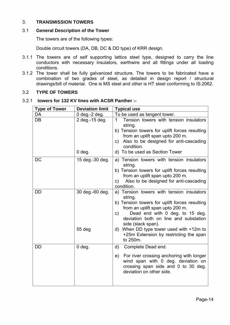
3.2.1 towers for 132 KV lines with ACSR Panther :-
Type of Tower Deviation limit Typical use DA 0 deg.-2 deg. To be used as tangent tower. DB 2 deg.-15 deg.
0 deg.
1 Tension towers with tension insulators string.
b) Tension towers for uplift forces resulting from an uplift span upto 200 m.
c) Also to be designed for anti-cascading condition.
d) To be used as Section Tower
DC 15 deg.-30 deg. a) Tension towers with tension insulators string.
b) Tension towers for uplift forces resulting from an uplift span upto 200 m.
c) Also to be designed for anti-cascading condition.
DD 30 deg.-60 deg. 55 deg
a) Tension towers with tension insulators string.
b) Tension towers for uplift forces resulting from an uplift span upto 200 m.
c) Dead end with 0 deg. to 15 deg. deviation both on line and substation side (slack span).
d) When DD type tower used with +12m to +25m Extension by restricting the span to 250m.
DD 0 deg.
d) Complete Dead end. e) For river crossing anchoring with longer
wind span with 0 deg. deviation on crossing span side and 0 to 30 deg. deviation on other side.
Page-14

3.2.2 EXTENSIONS 3.2.2.1 The towers for ACSR Panther Conductor lines has been designed for adding 3m,
6m, 9m, 12m, 15m, 18m & 25m body extensions for maintaining adequate ground clearance without reducing the specified factor of safety in any manner.
3.2.2.2 All above extension provision to normal towers shall be treated as part of normal
tower only. 3.3 SPANS AND CLEARNACES 3.3.1 NORMAL SPAN
The normal ruling span of the line shall be 300 meters. However the span length for DD type tower for using it with +12m, +18m & +25m Extension shall be restricted to 250m with angle of Deviation of 550 only.
3.3.2 WIND SPAN The wind span is the sum of the two half spans adjacent to the support under
consideration. For normal horizontal spans this equal to normal ruling span. 3.3.3 WEIGHT SPAN
Tower type Normal condition Max. Min. (m) (m)
Broken wire condition Max. Min. (m) (m)
DA DB, DC, DD
450 270 450 -200
225 100 225 -100
3.3.4 ELECTRICAL CLEARANCES 3.3.4.1 GROUND CLEARANCE
The min. ground clearances from the bottom conductor shall not be less than 6100 mm at the max. sag conditions i.e. at max. temperature and still air. However, to achieve the above clearance the height of tower has been increased in the following manner: a) An allowance of 150 mm has been provided to account for errors in stringing. b) Conductor creep shall be compensated by over tensioning the conductor at
temperature of 21oC lower than the stringing temperature for ACSR Panther. c) For river crossing tower the minimum electrical clearance including ground
clearance will be same as normal towers except an allowance of 4% of maximum sag of conductor instead of 150 mm for normal towers shall be provided to account for errors in stringing.
Page-15

3.3.4.2 LIVE METAL CLEARANCE
The minimum live metal clearance to be provided between the live parts and steel work of super structure shall be as per IS:5613 (part-ii/sec-1) 1985 as given in table below:
Sr. No
Type of insulator string Swing in deg. Min. live metal clearance in mm
1 Single suspension insulator string Nil 15 30 45 60
1530 1530 1370 1220 1070
2 Tension insulator string (single/double)
Nil 1530
3 Jumper Nil 10 20 30
1530 1530 1070 1070
4 Double suspension string Nil
15 30 45
1530 1530 1070 1070
3.3.4.3 MID SPAN CLEARNACE
The minimum vertical mid span clearance between the earthwire and the nearest power conductor shall not be less than 6.1 metres for 132 kV which shall mean the vertical clearance between earthwire and the nearest conductor under all emperatures and still air condition in the normal ruling span. Further, the tensions of the earthwires and power conductors shall be so co-ordinated that the sag of earthwire shall be at least 10% less than that of power conductors under all temperature loading conditions.
3.4 MAXIMUM TENSION 3.4.1 Max tension shall be based on either
a) At 0o C with 36% full wind pressure, of b) At 32o C with full wind pressure whichever is more stringent.
3.4.2 HVPNL has calculated sag-tension calculations for span of 300 metre for ACSR
Panther lines and earthwire size 7/3.15mm, which shall be provided to the successful bidder after award of contract.
3.4.3 The initial conductor tension at 32oC and without wind shall be 22% of the ultimate
tensile strength of the conductor. 3.4.4 LIMITING TENSION OF CONDUCTOR & EARTHWIRE
The ultimate tension of conductor and ground wire shall not exceed 70 percent of their ultimate tensile strengths.
Page-16

3.4.5 CONDUCTOR AND EARTHWIRE CONFIGURATION
The three phases shall be in triangular (L-shape) configuration for single circuit tower and in near vertical formation on both sides of tower for double circuit tower. The phase to phase spacing for tower shall be not less than 4.05 metres (vertical) and 7.06 metres (horizontal).
3.5 MATERIALS 3.5.1 TOWER STEEL SECTIONS 3.5.1.1 The towers for Panther conductor lines shall be fully galvanized structure of MS & HT
steel as per design/structural drawings/BOM. 3.5.2 FASTENERS: BOLTS NUTS AND WASHERS 3.5.2.1 All bolts and nuts shall conform to IS:6639-1972. All bolts and nuts shall be
galvanized and shall have hexagonal head and nuts, the heads being forged out of the solid steel rods and shall be truly concentric, and square with the shank, which must be perfectly straight.
3.5.2.2 The bolt shall be of 16 mm dia and of property class 5.6 as specified in IS:1367
(part-III) 1979 and matching nut of property class as specified in IS:1367 (part-VI) 1980.
3.5.2.3 Bolts up to M 16 and having length upto 10 times the diameter of the bolts should
be manufactured by cold forging and thread rolling process to obtain good and reliable mechanical Properties and effective dimensional control. The shear strength of bolts for 5.6 grade should be 310-MPa minimum as per IS: 12427, bolts should be provided with washer in accordance with IS: 1363 part-I to ensure proper bearing.
3.5.2.4 Nuts should be double chamfered as per the requirement of IS:1363 part-III, 1984.
The manufacturer should ensure that nuts should not be over – tapped beyond 0.4 mm oversize on effective diameter for size upto M16.
3.5.2.5 Fully threaded bolts shall not be used. The length of bolts shall be such that the
threaded portion will not extend into the place of contact of the members. 3.5.2.6 All bolts shall be threaded to take the full depth of the nuts and threaded for
enough to permit firm gripping of the members, but not further. It shall be ensured that the threaded portion of each bolt protrudes not less than 3 mm and not more than 8 mm when fully tightened. All nuts shall fit and tight to the point where the shank of the bolt connects to the head.
3.5.2.7 Flat and tapered washers shall be provided wherever necessary. Spring washers
shall be provided for insertion under all nuts. These washers shall be of steel electro-galvanised steel, positive lock type and 3.5 mm in thickness for 16 mm dia bolt.
Page-17

3.5.2.8 The bidder shall furnish bolt schedules giving thickness of members connected,
the size of bolts nut and the washer and the length of shank and the threaded portion of bolts and sizes of bolt holes and any other special details of this nature.
3.5.2.9 To obviate bending stress in bolts or to reduce it to minimum, no bolt shall connect
aggregate thickness of more than three (3) times its diameter. 3.5.2.10 The bolt position in assembled towers shall be as per IS:5613 (Part-II/secton-2-
1976). 3.5.2.11 Bolts at the joints shall be so staggered that nuts may be tightened with spanners
with out fouling. 3.5.2.12 To ensure effective in-process quality control it is essential that the manufacturer
should have all the testing facilities for test like weight of zinc coating, shear strength, other testing facilities etc. in-house. The manufacture should also have proper Quality Assurance System, which should be in line with the requirement of this specification and IS:14000 series quality system standard.
3.5.3 TOWER ACCESSORIES i) STEP BOLTS & LADDERS
Each tower shall be provided with step bolts in one of the main leg confirming to IS:10238 of not less than 16mm diameter and 175 mm long, spaced not more than 450 mm apart and extending form about 3.5 metres above the ground level to the top of the tower. The step bolt shall be fixed on one leg of single circuit tower from 3.5 m above ground level to top of the towers. Each step bolt shall be provided with two nuts on one end to fasten the bolt securely to the tower and button head at the other end to prevent the feet from slipping away. The step bolts shall be capable of withstanding a vertical load not less than 1.5 KN. For special structures, where the height of the super structure exceeds 50 metres, ladders along with protection rings as per the HVPNL approved design shall be provided in continuation of the step bolts on one face of the tower from 30 metres above ground level to the top of the special structure. From 3.5 m to 30 m height of super structure step bolts shall be provided. Suitable plat form using 6 mm thick perforated chequred plates along with suitable railing for access from step bolts to the ladder and from the ladder to each cross-arm tip and the groundwire support shall to be provided. The platform shall be fixed on tower by using countersunk bolts.
ii) INSULATOR STRING AND EARTHWIRE CLAMPS ATTACHMENTS
a) ‘I’ shaped suspension insulator string assemblies shall be used for suspension towers, the drawing of which is enclosed with specification. For the attachment of suspension insulator string, a suitable dimensioned swinging hanger on the tower shall be provided so as to obtain requisite clearance under extreme swinging condition and free from swinging of the string. The hanger shall be designed to withstand an UTS of 70 KN for single suspension string and 140 KN for double suspension string.
Page-18
b) At tension towers, strain plates of suitable dimensions on the underside of each
cross-arm tip and at the top earthwire peak should be provided for taking the hooks or D-shackle of the tension insulator strings or earthwire tension clamps, as the case may be. Full details of the attachments shall be submitted by the bidder for HVPNL approval before starting the mass fabrication.
iii) EARTHWIRE CLAMPS
SUSPENSION CLAMP Earthwire suspension clamps will be supplied by the bidder, the reference drawing for the same is enclosed with the specification. Earthwire peaks/cross-arms are to be suitably designed to accommodate the shackle of the suspension clamp.
TENSION CLAMPS The bidder shall supply earthwire tension clamps for incorporation on the tension towers. The reference drawing for the same is enclosed with this specification.
iv) ANTICLIMBING DEVICE
Barbed wire type anticlimbing device/ fencing as per enclosed drawing shall be provided and installed by the Bidder for all towers/gantries. The height of the anticlimbing device shall be provided approximately 3m above ground level. The barbed wire shall conform to IS:278-1978. the barbed wires shall be given chromating dip as per procedure laid down in IS:1340-1959.
v) DANGER, NUMBER, AND PHASE PLATE
Danger, Number, Circuit and phase plates shall be provided and installed by the Bidder.
a) Each tower shall be fitted with a number plate, circuit plate (in case of double
circuit) and danger plate. Each tension tower shall be provided with a set of phase plates also. All the double circuit towers are to be provided with circuit plate fixed near the legs. The height for fixing these accessories shall not be more than 4.5m above the ground level.
b) The letters figures and the conventional skull and bones of danger plates shall
conform to IS:2551-1963 and shall be in a signal red on the front of the plate.
c) The corners of the number, danger & circuit plate shall be rounded off to remove sharp edges.
Vi) BIRD GUARDS
To prevent birds perching immediately above the suspension insulator string and fouling the same with dropping, suitable bird guards shall be provided at cross arm tips of all suspension towers. The bird guard arrangement shall be such that it shall either prevent bird from perching in position where they are liable to cause the damages or ensure that if birds do perch, dropping will fall clear of the insulator string.
Page-19

3.6 TOWER FABRICATION FOR 132KV LINES
The fabrication of towers shall be in conformity with the following: 3.6.1 Except where hereinafter modified, details of fabrication shall conform to IS:802 (Part-
II) 1978 or the relevant international standards. 3.6.2 The tower structure shall be accurately fabricated to connect together easily at site
without any undue strain on the bolts. 3.6.3 The diameter of the hole shall be equal to the diameter of bolt plus 1.5 mm. 3.6.4 All similar parts shall be made strictly inter-changeable. All steel sections before any
work is done on them, shall be carefully leveled, straightened and made true to detailed drawings by methods which will not damage the materials so that when assembled, the adjacent matching surfaces are in close contact throughout. No rough edges shall be permitted in the entire structure.
3.6.5 DRILLING AND PUNCHING 3.6.5.1 Before any cutting work is started, all steel sections shall be carefully straightened
and trued by pressure and not by hammering. They shall again be trued after being punched and drilled.
3.6.5.2 Holes for bolts shall be drilled or punched with a jig but drilled holes shall be
preferred. Punching may be adopted for thickness upto 16mm. tolerances regarding punched holes are as follows:
a) Holes must be perfectly circular and no tolerance in this respect is permissible. b) The max. allowable difference in diameter of the holes on the two sides of
plates or angle is 0.8 mm i.e. the allowable taper in a punched hole should not exceed 0.8 mm in diameter.
c) Holes must be square with the plates or angles and have their walls parallel.
3.6.5.3 All burrs left by drills or punch shall be removed completely. When the tower
members are in position the holes shall be truly opposite to each other. Drilling or reaming to enlarge holes shall not be permitted.
3.7.1 ERECTION MARK 3.7.1.1 Each individual member shall have an erection mark conforming to the component
number given to it in the fabrication drawings. This mark shall be made with marking dies of 16 mm size before galvanizing and shall be legible after galvanizing.
3.7.1.2 ERECTION MARK SHALL BE
A-BB-CC-DDD A = HVPNL code assigned to the Bidder -Alphabet BB = Bidder’s Mark-Numerical
Page-20

CC = Tower type-Alphabet DD = Number mark to be assigned by Bidder -Numerical. HT = High Tensile steel
3.7.2 QUANTITIES VARIATION 3.7.2.1 The provisional quantities required are mentioned in the respective schedule of
prices. Final quantities shall be determined after completion and approval of the detailed route survey and check survey. The final quantities of towers, gantries, line materials and foundations shall be confirmed by the HVPNL based on the requirement of quantities of various items furnished by the Bidder after completion of detailed survey. Hence it will the responsibility of the Bidder to intimate the exact requirements of all towers, line materials and foundations required for the line immediately after the survey. The Empowered officer of the HVPNL will order the final quantities at the unit rates quoted in the bid.
3.7.2.2 The Empowered officer of the HVPNL reserves the right to increase or decrease
upto 15% (fifteen percent only) of contract value. The quantity of bid and services specified without any change in the unit price or other terms and conditions during the execution of the contract. The quantities of individual items may vary upto any extent after the final route plans and route profiles of the lines covered in the package are finalised.
3.7.2.3 The estimated unit weight of each type of tower, stubs and extensions shall be
furnished by the HVPNL. The weight of tower shall mean the weight of tower calculated by using the black sectional (i.e. ungalvanised) weight of steel members of the size indicated in the approved fabrication drawings and bills of materials, without taking into consideration the reduction in weights due to holes, notches and bevel-cuts etc. but taking into consideration the weight of fastners, anticlimbing devices etc.
For payment purpose, the round plane washers, hangers, D-shackles, U-bolts, step bolts, spring washers, bolts and nuts etc. shall be termed as fasteners.
3.8 GALVANISING Fully galvanized towers and stub shall be used for the lines. Galvanizing of the
member of the towers shall conform to IS:2629-1985 and IS:4759-1968. All galvanizing members shall withstand tests as per IS:2633-1986. For fasteners the galvanizing shall conform to IS:1367 (Part-13). The galvanizing shall be done after all fabrication work is completed, except that the nuts may be tapped or re-run after galvanizing. Threads of bolts and nuts shall have a neat fit and shall be such that they can be turned with finger throughout the length of the threads of bolts and they shall be capable of developing full strength of the bolts. Spring washers shall be electro-galvanised as per grade 4 of IS: 1573-1970.
Page-21

3.9 EARTHING 3.9.1 The footing resistance of all towers shall be measured by the Bidder in dry weather
after tower erection but before the stringing of earthwire. All the towers are to be earthed, however, in no case tower footing resistance shall exceed 10 ohms. Pipe type earthing and counterpoise type earthing wherever required shall be provided in accordance with the stipulations made in IS:3034-1987 and IS:5613 (part-II/section-2) 1985. The details for pipe and counterpoise type earthing are given in drawing enclosed with the specification.
3.9.2 The provisional quantities for pipe type earthings and counterpoise earthing, are
furnished in price schedule. The bidders are required to furnish unit rates also for adjustment purpose with actual quantities. The quoted price shall include fabrication, supply and installation of earthing material including supply of coke, salt etc. in case of counterpoise type earthing, the quotation shall be based on 100 metres of wire per tower.
3.10 INSPECTION AND TESTS 3.10.1 All standards tests, including quality control tests, in accordance with appropriate
Indian/International standard, shall be carried out unless otherwise specified herein. 3.10.2 All Goods being supplied shall conform to type tests, sample tests as per the
technical specifications and shall be subject to routine, acceptance and site tests in accordance with requirements stipulated under the respective Sections, unless otherwise stated. The HVPNL reserves the right to witness any or all the type and sample tests. The Bidder shall inform the HVPNL of the detailed program of tests at least two (2) weeks in advance in case of domestic supplies and four (4) weeks in advance in case of foreign supplies.
3.10.3 The Bidder shall furnish to HVPNL the reports of all type tests, sample and routine
tests as per technical specification along with the equipment/materials drawings. The type tests conducted earlier should have been conducted in accredited laboratories (based on ISO/IEC by a reputed accreditation body) or witnessed by HVPNL or another electric power utility. The type test reports submitted shall be of the tests conducted within last five (5) years prior to the date of bid opening. In case the test reports are of a test conducted five (5) years prior to the date of bid opening, and don’t correspond to the offered equipment/material, or don’t comply with the Technical Specifications, the Bidder shall repeat this / these test / tests at no extra cost to the HVPNL before sample(acceptance) tests. The cost of conducting type tests and additional tests shall be included in the Bid price .
3.10.4 The HVPNL, his duly authorized representative and/or outside inspection agency
acting on behalf of the HVPNL shall have free access at all reasonable times to the Bidder’s/sub-vendor’s premises or Works and shall have the power at all reasonable times to inspect and examine the equipment/materials and workmanship of the Works during its manufacture or erection. If part of the Works is being manufactured or assembled at other premises or works, the Bidder shall obtain for the HVPNL, his duly authorized representatives and/or outside inspection agency permission to inspect as if the works were manufactured or assembled on the Bidder’s own premises or works. Inspection may be made at any stage of manufacture, dispatch or at the Site at the option of the HVPNL, and the equipment if found unsatisfactory due to bad workmanship or quality or material is liable to be rejected.
Page-22

When the factory tests have been completed at the Bidder’s or Sup-Bidder’s works, the HVPNL/Inspector shall issue a certificate to this effect within fifteen (15) days after the completion of the tests, but if the tests are not witnessed by the HVPNL/Inspector, the certificate shall be issued within 15 days of receipt of the Bidder’s test certificate by the HVPNL’s representative. Failure of the HVPNL/Inspector to issue such a certificate shall not prevent the Bidder from proceeding with the Works (as defined in SCC). The completion of these tests or the issue of the certificate shall not bind the HVPNL to accept the equipment/materials should it, on further tests after erection, be found not comply with the Contract. The equipment/materials shall be dispatched to Site only after approval of test reports and issuance of the inspection certificate by the HVPNL.
3.10.5 The inspection by the HVPNL and issue of the inspection certificate thereon shall in
no way limit the liabilities and responsibilities of the Bidder in respect to the agreed quality assurance program forming part of the Contract.
3.10.6 The HVPNL will have the right of having at his own expenses any other test(s) of
reasonable nature carried out at the Bidder’s premises or at any other place in addition of aforesaid type and routine tests to satisfy that the equipment/materials comply with the specifications.
3.10.7 The HVPNL deserves the right for getting any field tests not specified in the
respective sections of the technical specifications conducted on the completely assembled equipment at Site. The HVPNL will provide the testing equipment for these tests.
3.10.8 The Bidder shall ensure that his subBidders manufacturing and supplying the goods
(material and equipment) shall perform the routine tests specified in the related standards and in the Technical Specifications of this Contract regularly.
3.10.9 The Bidder shall notify the HVPNL in writing at the latest four (4) weeks for
inspection outside of India and two (2) weeks for local inspection and testing or as otherwise directed in advance of the date and place at which any Material or Work will be ready for inspection and testing.
3.10.10 Should any postponement become necessary, the Bidder shall provide written
notification at least one week prior to the originally scheduled date. The HVPNL shall give 48 hours' notice in writing to the Bidder, of his intention to attend the tests, or ask for postponement, if required.
3.10.11 Should the HVPNL explicitly waive to attend the relevant test, the Bidder may
proceed with the test, which shall be deemed to have been made in his presence, and the Bidder shall forthwith forward to the HVPNL duly certified copies of the test reports for approval.
3.10.12 All sample and type tests will be performed at the presence of the authorized
personnel of the Bidder or inspectors authorized by the Bidder, if there is no representative of HVPNL.
3.10.13 HVPNL may or may not be present in any or all sample and type tests but all test
reports shall be approved by HVPNL Page-23

3.10.14 This procedure shall not release the Bidder from any of his responsibilities or
obligations under this Contract. 3.10.15 The Bidder shall prepare and agree with HVPNL test programs so that tests to be
performed in foreign countries (i.e., at manufacturer's factory or at internationally recognized test facilities) are carried out in sequence which would permit HVPNL to organize in an optimal manner the supervision of the said tests by HVPNL staff.
3.11 Galvanizing Tests:
All fabricated materials shall be tested in accordance with the "Test and Inspection Procedures for Galvanized Materials "as per Specification and HVPNL shall be notified at least thirty days in advance of any tests if it is performed in abroad.
3.12 Inspections and Tests: The Bidder shall make adequate tests and inspections to
determine whether the material furnished is strictly in accordance with this Specification. In addition, HVPNL may inspect and accept or reject the material made under this Specification either at the Fabricator's plant or at the point of delivery The representatives of HVPNL shall have access to all parts of the Bidder's plant which concerns the Work while the Work is being done. The Bidder, without requesting any fee, shall provide all the reasonable facilities to the HVPNL's representatives so as to satisfy them that, the towers are manufactured strictly in compliance to this Specification.
3.13 Certified Tests: Regardless of whether the material is inspected by HVPNL , the
Bidder shall furnish certified test reports as follows: a) Steel Mill Test Reports showing chemical, physical and mechanical properties of the material to be furnished under the Contract. b) A Manufacturer's Certificate of Inspection for zinc (hot-galvanized) coatings on structural steel with the following information: 1- Purchase order number 2- Date of inspection 3- Number of pieces tested for weight of zinc coating with maximum-minimum
and average weights of each. 4- Number of pieces tested for adherence of coating. 5- Number of rejections because of defective coating and other reasons.
Certified test reports shall be sent to HVPNL.
3.14 Shop assembly: One tower of each type and height ordered, including every combination of leg extensions, shall be assembled in the shop to the extent necessary to assure correct fit of parts, adequate bolt lengths and proper field erection. Reaming of mismatched holes will not be permitted. A reasonable amount of drifting will be allowed in assembling approved by HVPNL. The approved assembled parts shall be dismantled for shipment. Shop assembly shall be controlled and approved by HVPNL.
Page-24
3.15 Fabrication: Fabrication shall be in strict accordance with detail Drawings prepared
by the Bidder and approved by the HVPNL. The drilling, punching, cutting and bending of all fabricated steelwork shall be such as to prevent any possibility of irregularity occurring which might introduce difficulties in the erection of the structure on the site.
Built pieces shall, when finished, be true and free from all kinks, twists and open joints and the Material shall not be defective or strained in any way. Fabrication shall begin after the approval of the shop assembly. 3.16 IDENTIFICATION AND SHIPPING
Identification: All parts designed for bolting together shall be shipped unassembled except as noted on the drawings. Tower members shall be bundled together in the largest practical bundles for shipping and each bundle shall be clearly marked. Small parts such as U-bolts and clip angles shall be boxed and each box clearly marked for identification. Shipping: Railroad cars, ships or trucks in which steel is shipped shall be reasonably clean and free from foreign materials which could in any way injure the tower material. At least 8cm clearance shall be maintained between bundles and floor.
3.17 GENERAL
All standards tests, including quality control tests, in accordance with appropriate Indian/International standard, shall be carried out unless otherwise specified herein.
3.18 INSPECTION 3.18.1 In addition to the provision of clause regarding inspection in conditions of contract,
the following shall also apply:
a. The Bidder shall keep the HVPNL informed in advance about the time of starting and of the progress of manufacture and fabrication of various tower parts at various stages, so that arrangements can be made for inspection.
b. The acceptance of any part of items shall in no way relieve the Bidder of any part of his responsibility for meeting all the requirements of the specification.
3.18.2 The HVPNL or his representative shall have free access at all reasonable times to
those parts of the Bidder’s works which are concerned with the fabrication of the HVPNL material for satisfying himself that the fabrication is being done in accordance with the provisions of the specifications.
3.18.3 Unless specified otherwise, inspection shall be made at the place of manufacture prior
to dispatch and shall be conducted so as not to interfere unnecessarily with the operation of the work.
3.18.4 Should any member of the structure be found not to comply with the approved design,
it shall be liable to rejection. No member once rejected shall be re-offered for inspection, except in cases where the HVPNL or his authorized representative considers that the defects can be rectified.
Page-25

3.18.5 Defect which may appear during fabrication shall be made good with the consent of
and according to the procedure proposed by the Bidder and approved by the HVPNL. 3.18.6 All gauges and templates necessary to satisfy the HVPNL shall be supplied by the
manufacture. 3.18.7 The correct grade and quality of steel shall be used by the Bidder. To ascertain the
quality of steel used, the inspector may at his discretion get the material tested at an approved laboratory.
3.19 TESTING OF TOWER
As the towers to be fabricated have already been tested hence testing of towers is not required.
3.20 STANDARDS
3.20.1 The material and services covered under these specifications shall be performed as per requirements of the relevant standards/codes (which shall mean latest revisions, amendments/changes adopted and published unless otherwise specified) referred hereinafter against each set of equipment and services. Other internationally acceptable standards.
SR No.
INDIAN STANDARDS
TITLE INTERNATIONAL & INTERNATIONALLY RECOGNISED STANDARDS.
1 2 3 4
1 IS:209-REV, Specification for Zinc ISO/R/752-1968 ASTM B6
2 IS:226-1975 Structural steel Standard quality
ISO/R/630-1967 CAN/CSA-G40.21 BS 4360
3 IS:269-1976 Ordinary rapid hardening & low heat Portland cement.
ISO/R/597-1967
4 IS:383-1970 Coarse and fine aggregates from natural sources for concrete.
CSA A23, 1/A 23.2
5 IS:278 Specification for barbed wire. ASTM A 121
6 IS:432-1966 Mild steel and medium (part-I&II) Drawn steel wire for concrete reinforcement.
BS-785-1938 tensile bars and hard CSA-G-30.
7 IS:456-2000 Code of practice for plain and reinforced concerete.
ISO/3893-1977
Page-26

8 IS:800-1962 Code of practice for use of
structural steel in general building construction.
CSA S16.1
9 a) IS:802 Code of practice for use of structural steel in overhead transmission line. Materials loads and permissible stresses.
IEC 826 ASCE 52 BS 8100
b)IS:802 (part-II) 1978
Code of practice for use of structural steel in overhead transmission line. Fabrication, galvanizing, inspection and packing.
ASCE 52
c)IS:802 (part-III) 1978
Code of practice for use of structural steel in overhead transmission line. Tower testing.
10 IS:808 Dimensions for Hot Rolled steel beam, column, channel and angle sections
11 IS:875 Code of practice for design loads (other than earth-quakes) for buildings & structures.
12 IS:1367-1967 Technical supply conditions for threaded fasteners (first revision)
13 IS:1489-1976 Portland pozzolena cement ISO/R/863-1968
14 IS:1786-1989 Cold twisted steel bars for concrete reinforcement.
15 IS:1893-1965 Critecia of earthquake resistant design of structures
IEEE 693
16 IS:2016-1967 Plain washers ISO/R/887-1968. ANSI B18.22.1
17 IS:2131-1967 Method of standard penetration test for soils.
ASTM D 1883
18 IS:2551-1982 Danger notice plates
19 IS:2629-1966 Recommended practice for hot dip galvanizing of iron & steel.
ASTM A 123 CAN/CSA-G164.
20 IS:2633-1972 Method of testing uniformity of coating of zinc coated articles.
ASTM A 123 CAN/CSA-G164.
Page-27

21 IS:3043-1972 Code of practice of earthing (with amendment No. 1and 2)
22 IS:3063-1972 Single coil rectangular section spring washers for bolts, nuts, screws.
DIN-127-1970
23 IS:4091-1967 Code of practice for design and construction of foundation for transmission line towers and poles.
ASCE/IEEE 691
24 IS:5358-1969 Hot dip galvanizing coatings on fasteners.
ASTM A 153 CAN/CSA-G164.
25 IS:5613 (part-II/Sec.-1) 1976
Code of practice for design, installation and maintenance of overhead power lines (Sec-1: (Designs)
ASCE 52
26 IS:5613 (part-II/Sec.-2) 1976
Code of practice for design, installation and maintenance of overhead power lines (Sec.-2 installation and maintenance)
27 IS:6610-1972 Specification for heavy washers for steel structures.
28 IS:6639-1972 Hexagonal bolts for steel structure. ASTM, A 394 CSA B33.4 29 IS:6745-1972 Methods for determination of
weight of zinc coating of zinc coated iron and steel articles.
ASTM A90
30 Indian electricity rules – 1956
31 Publication No. 19 (N) 700-1963
Regulation for electrical crossing of Railway Tracks.
32 IS:8500-1977 Specification for weldable structural steel (medium and high strength qualities)
BS: 4360
33 IS:2062-1992 Steel for general structural purposes.
Page-28

The standards mentioned above are available from: - Reference/Abbreviation Name and address from which the standards are
available. IS Bureau of Indian standards, Manak Bhawan, 9 Bahadur
Shah Zafar Marg, New Delhi, INDIA.
ISO International Organisation for standardization, Danish Board of Standardisation Danisk Standardisening Sraat, Aureheeugej-12, DK-2900 Helleprup DENMARK.
CSA Canadian Standard Association, 178, Rezdale Boulevard, Rexdale, Ontario, CANADA, M9W IR
BS British Standsrds, British Standard Institution, 101, Pentonvile Road, N-19-ND, UK.
DIN Deutsches Institue Firr Normung Burggafenstrasse 4-10 Post Fach 1107 D-1000, Berlin-30
Indian Electricity Rules 1956 Regulation for Electricity Crossing of Railway Tracks.
Kitab Mahal ,Baba Kharak Singh Marg, New Delhi-110001 INDIA.
ASCE American Society of Civil Engineers, 345, East 47th Street, New York, NY-10017-2398 USA
IEEE Institute of Electrical and Electronic Engineers ,445, Hoes Lane PO. Box, 1331 Piscatawa NJ-08855-1355 USA
IEC International Electrotechnical Commission Bureau central de La commission Electrotechnique internatinale 1. Rue de varombe Geneva Switzerland
Page-29

3.20 MONTHLY PROGRESS REPORTS
For the control of the works by the HVPNL, the Bidder shall prepared detailed monthly progress reports in following form: These reports show the progress of material orders and procurement, material shipments, construction and assembly works included in the contract. It will also include but not limited to commencement dates, percentage of completion (with regards to the affected payments vs. Total contract amount excluding escalation and to the physical realization of works) and expected completion dates. Progress reports shall show manufacture of goods and construction operations for each item of work the time work under the contract started to the anticipated completion date, there by indicating the periods during which was previously underway as well as estimated future periods of manufacture and construction operations. Two (2) copies of the monthly progress reports which are prepared at the end of each calendar month by the Bidder shall be submitted to the HVPNL not later than seven (7) days after the close of the reporting period. Bidder : Contract No : Bidder's Site Engineer(s) : (name, telephone and fax. number) Civil Engineer(s) : Electrical engineer(s) : Supervisor(s) : Site test engineer(s) : Commissioning engineer(s) : HVPNL's Control Engineer(s) : (name, telephone and fax. number) Civil Engineer : Electrical Engineer : Project Report No : Month from ......to....... CHAPTER I - General CHAPTER II i) List of letters submitted by Consortium ii) List of letters send by the HVPNL iii) Photocopies of minutes of meeting iv)List of project submitted and stage (indicate revision)
Page-30
CHAPTER III - Work Activity - Delivery of goods (shipped, arrived to port, at customs arrived to side in good condition not) * Supplied by Bidder a) Local b) Foreign - Civil Works - Erection - Site test -Overall function test CHAPTER IV - Problem and difficulties confronted with indicating agreements and disagreements. CHAPTER V - Work program expected to be done next month
Page-31

G-10 (Package-A) 4.0 TOWER FOUNDATION
4.1 GENERAL
These specifications provide as per unit rates of foundations shown in the bidder and general guidelines for the construction of tower foundations as per design supplied by HVPNL and the gantry tower foundations as per design supplied by HVPNL of the proposed transmission line(s) covered in the tender.
4.2 Before start of work, successful bidder shall carry out trial bore-holes (normally up to 6.0 meter below natural ground level) after every Kilometer en-route or as desired by the HVPNL to have a fair idea of soil type/nature and subsoil water position. If the soil characteristics are changing rapidly or soil up to 6.0 meter is very weak, the depth of bore-hole be increased beyond 6.0 meters so as to know the soil properties/type below the foundation. The bore log data containing information such as position of sub-soil water table, soil strata, the crop pattern in the agricultural fields where the foundation is to be laid and the suitability for founding the required foundation, shall be submitted to the HVPNL for according approval for “Classification of foundation” at each location.
4.3 TYPE OF SOIL
Soil en-route the following proposed transmission lines under the scheme is generally normal/Sandy/rocky.
3 WBS-G-10- (Package-A)
1. LILO OF BOTH CIRCUIT 220 KV FATEHABAD- CHORMAR D/C LINE AT PROPOSED 220KV SUBSTATION HUKMAWALI WITH ACSR MOOSE CONDUCTOR-42KM(APPROX.).
2. LILO OF 220KV D/C CHEEKA- DURALA LINE AT PROPOSED 220KV
SUBSTATION SONTA WITH 0.4 SQ. INCH ACSR-ZEBRA 20+20=40KM(APPROX.).
3. LILO OF SECOND CIRCUIT OF 220KV D/C PEHOWA –SHAHBAD LINE AT
220KV SUBSTATION DURALA WITH 0.4 SQ. INCH ACSR- ZEBRA-3KM(APPROX.).
4. LILO OF EXISTING CIRCUIT OF 132KV RATIA-AHERWAN S/C ON D/C TOWER
LINE AT 220KV SUBSTATION HUKMAWALI WITH ACSR PANTHER-13KM (APPROX.).
Ground water table enroute all the above said lines generally vary from 30ft. to 100ft. below Natural Ground Level. The sub soil water level at few locations may be different due to local conditions. The crop pattern enroute all the above said lines is paddy, wheat, sugarcane, cotton etc. depending on soil and weather conditions.
4.4 CLASSIFICATION OF SOIL
a. Dry Soil: Soil shall be termed as dry soil where sub-soil water table is below base of the tower footing and no de-watering is required.
Page-32
b. Wet Soil (without de-watering): Soil shall be termed as wet soil (without de-watering) where sub-soil water is below base of footing and no de-watering is required but crop pattern is paddy field.
c. Wet Soil (with de-watering): Soil shall be termed as wet soil (with de-
watering) where sub-soil water is above base of footing and de-watering has to be done.
d. Rocky Soil: Hard conglomerate or other soft or fissured rock which can be
quarried or split with crow bars, wedges or pick axes. However, if required, light blasting may be resorted to for loosening the material.
4.4.1 For excavation purpose, the quoted rates for foundations in wet soil (without de-
watering) shall be considered as applicable for the dry soils. For wet soil (with de-watering), the quoted rates shall be inclusive of de-watering. The de-watering operation shall continue to keep the foundation pits dry during concreting and thereafter for at least 24 hrs. Any de-watering carried out for removal of seepage of surface water/rainwater will not be considered as de-watering and the soil shall be termed as ‘Dry Soil’.
4.5 FOUNDATION TYPES 4.5.1 GENERAL
Reinforced cement concrete footing shall be used for all types of normal towers/ extension towers in conformity with the present day practices followed in the country and the specifications laid herein. All the four footings of the tower and their extensions, if any shall be similar irrespective of down thrust and uplift.
4.5.2 Foundation includes supply of materials such as cement, fine and coarse aggregates,
water, reinforcement steel and binding wire etc. Rates quoted for foundations shall include all items of work relating to supply and installation of foundations such as form work, excavation and backfiling with good soil, compaction, stub setting, shoring & timbering etc. where ever required, placing of reinforcement in position, concreting and all other works related for completion of foundation.
4.6 CLASSIFICATION OF FOUNDATIONS
a. Dry Foundation: To be used where sub-soil water table is below 6.0 meter
from Natural Ground Level. b. Wet Foundation (without de-watering): To be used where sub-soil water
table is below base of footing and up to 6.0 meters from Natural Ground Level or at location where surface water remains for long periods such as paddy/sugar cane fields irrespective of sub-soil water depth.
c. Wet Foundation (with de-watering): To be used where sub-soil water table is
above footing base of foundation and actual de-watering has to be carried out for construction of foundation.
d. Well foundation - To be used where the line crossing the river/ and towers foundation are coming in the river bed.
Page-33

4.6.1 Design of foundation for Wet (without de-watering) and Wet (with de-watering) shall
be same. 4.7 PROPERTIES OF CONCRETE & REINFORCEMENT 4.7.1. All the properties of concrete regarding its strength under compression, tension, shear,
punching and bond strength etc. as well as workmanship shall confirm to IS: 456. 4.7.2 The concrete used as lean concrete or base concrete shall be as mentioned on
respective drawings. The aggreg ate size shall be 40 mm nominal. Base concrete shall be well compacted. The top surface of base concrete shall be leveled before placing the reinforcement.
During excavation, if excavation exceeds the required depth or if any loose pocket of earth is met below the base of footing, then the loose earth shall be removed or excavation depth be increased till normal hard soil is met as per satisfaction of the Engineer-in-Charge. This extra depth shall be filled with lean concrete. No extra shall be paid on account of this extra excavation and lean concrete.
4.7.3 The cement concrete used for foundation shall be of grade M-20 {irrespective of any
grade mentioned on the drawing(s)}. The Mix Design (conforming to IS standards) shall be done prior to start of work, as per specifications, got approved from the HVPNL and shall be used for the construction, provided there is no change in the source and the quality of materials. The source of materials shall be intimated to the HVPNL and shall be ensured that Mix Design is with the materials from intimated source only and same is not changed during construction. In case source of material changes or quality of material differs from the earlier approval parameters the Mix Design shall be done again.
4.7.4 The coarse aggregate used shall be 20 mm graded or two types of single size
aggregate mixed in some fixed ratio to have graded 20-mm aggregate. The Coarse aggregate shall conform to IS 383.
4.7.5 Grading of Fine aggregate shall conform to Zone-II of Table-4 of IS: 383 and shall be
free from deleterious materials. 4.7.6 The environmental exposure condition considered for Mix Design shall be MILD. 4.7.7 For Mix Design the degree of quality control shall be considered as FAIR. 4.7.8 The Water Cement ratio shall be minimum 0.50 and maximum 0.55. 4.7.9 For Transmission Line Tower footings, the minimum Slump shall be 50 mm and
maximum 75 mm. 4.7.10For volumetric use of ingredients for concrete mix, the contractor along with the Mix
Design shall intimate the size of measuring boxes along with the Mix design. 4.7.11The approval of Mix Design shall not absolve the contractor from the responsibility of
achieving the required strength, workability etc. during actual execution. In case of failure of concrete samples, the work done is liable to be rejected. In such case the contractor shall recast the foundation at the same location by dismantling the rejected foundation or at a near by location as directed by the HVPNL. In case of honey
Page-34
combing, the contractor shall do the pressure grouting as directed and to the full satisfaction of HVPNL. The construction of new foundation in place of rejected one and pressure grouting if done shall be without any extra payment.
4.7.12 Ordinary Portland_Cement of Grade 43 conforming to IS: 8112 shall be used.
However in case of shortage of OPC Cement, Portland Pozzolona Cement (fly ash based or calcinated clay based) conforming to IS 1489 Part Part – 1 and – 2 respectively may be used in the works other than RCC. In case, Portland Pozzolona Cement is used then curing period shall be enhanced as directed by Engineer-in-Charge. In RCC works only Ordinary Portland_Cement of Grade 43 shall be used.
4.7.13The water used for mixing concrete and for curing purpose shall be fresh, clean and
free from oils, acids and alkalis, organic materials or other deleterious substance. Potable water is generally preferred. Saltish or brackish water shall not be used. Water used shall conform to clause 5.4 of IS 456.
4.7.14 Reinforcement steel (including TMT) Bars manufactured by TISCO, SAIL, IISCO and
RASHTRIYA ISPAT (primary manufacturers) conforming to IS: 1786 for deformed and cold twisted bars shall only be used. The bidders shall, however, be allowed to use Amba steel, Rathi steel, Kamdhenu steel, Barnala steel, P.R.S steel, Shidbali steel (manufactured by secondary manufacturers) only after obtaining non-availability certificate from the primary manufacturers. Before using secondary steel, the selected bidder would require to conduct all physical & chemical tests (lot wise & dia. wise) to establish its conformity to IS Standards. Required grade of steel shall be Fe-415. All reinforcement shall be clean and free from loose mill scale, dust, loose rust and coats of paint, oil or other coating, which may destroy or reduce bond with concrete. Reinforcement bars should be fresh. Contractor shall supply, fabricate and place reinforcement to shapes and dimensions as indicated on the drawings or as required to carry out the intent of drawings and specifications. Adequate nos. of chairs, spacers of required size shall be provided to ensure the proper placement of reinforcement. The reinforcement bars crossing one another should be tied together at every intersection with two strands of annealed steel wires 0.9 to 1.6 mm thick twisted and tied to make the skeleton of the steel work rigid so that the reinforcement does not get displaced during concrete placement.
All the reinforcement steel should be placed/ stacked at site store on raised (at least 0.5 meter from near surroundings) pucca/brick platform or reinforcement steel should be placed on MS/GI sheets. The reinforcement steel after stacking should be covered with Tarpaulin to avoid corrosion. Immediately before concreting (portion of reinforcement to be embedded in concrete) shall be painted with cement slurry after removing any rust/corrosion/any other foreign material.
4.7.15 No admixtures shall be used. 4.8 UNIT RATES AND MEASUREMENT 4.8.1 The rates of foundation shall be per tower. These rates shall include excavation, stub
setting, concreting, reinforcement, shuttering, shoring/ timbering, stockpiling, dressing, curing, back filling (after concreting) with good (excavated/borrowed) earth irrespective of lead. Rates are inclusive of compaction of earth, carriage of surplus earth to suitable disposal location as required by HVPNL or any other activity related to completion of foundation works in all respects.
Page-35

4.8.2 The bidder shall also furnish unit rates in bid-proposal sheet(s). These unit rates when
multiplied with volumes/quantities of foundation {as per drawings or attachments with the tender as separate sheet(s)} shall match with the rates quoted for foundation per tower. In case of discrepancy, lower of the two rates i.e. rate quoted per tower foundation and the rate derived by multiplying the unit rates with total quantities shall be payable.
4.8.3 In case of any change/variation in the foundation drawing(s) attached with bidding
document, due to site conditions or otherwise, the payment shall be made based on unit rates quoted.
4.9 CONSTRUCTION OF TOWER FOUNDATIONS AS PER DESIGN SUPPLIED BY
HVPNL 4.9.1 EXCAVATION
Excavation work shall start only after the approval of route plan, the tower foundation schedule, classification of foundations and the profile by the HVPNL. The reference natural ground level shall be so chosen that it is not lower than surroundings and in normal condition water does not accumulate there, preferably it should be slightly higher than surroundings.
All excavation for footing shall be made to the lines and grades of the foundation. The excavation wall shall have stable slope and the pit dimensions shall be such as to allow a clearance of 150 mm on all sides from the foundation RCC pad. The contractor should ensure clearance of 150 mm from the foundation RCC pad for quality work. All excavation shall be protected so as to maintain a clean sub-grade until the footing is placed, using timbering/shuttering, shoring etc., if necessary. Any sand, mud, silt or other undesirable materials, which may accumulate in the excavated pit, shall be removed by the contractor before placing concrete.
4.9.2 No extra charges shall be admissible for the removal of the fallen earth in the pit, when
once excavated. 4.9.3 Wherever ground water table is higher than the base of the foundation, it has to be
depressed by de-watering. During de-watering, water shall be thrown at a place as directed by the Engineer-in-Charge. No pit de-watering shall be permitted. Instead, over all lowering of the water table shall be done by providing sufficient number of bores around the tower location and by continuous pumping of water through these bores. Well point system for de-watering of pits can also be adopted. It must be ensured that during de-watering/pumping operation, no finer particles of soil get displaced or any cavity is formed below. The boreholes for de-watering shall be located so as to avoid any hindrance in normal working for construction of foundation. The construction of foundation shall be carried out in bone-dry condition, which shall be ensured by effective lowering of water table so that no caving in happens and also the bottom of the pit is free from slushy conditions. The bores shall be filled with sand after the work at a particular location is over.
Page-36

4.10 SETTING OF STUBS
The stubs shall be set correctly in accordance with approved method at the exact location and aligned precisely at correct levels with the help of stub setting templates and leveling instruments. Stubs shall be set in the presence of HVPNL’s representative for which the Contractor shall give adequate advance intimation to the HVPNL. All necessary precautions should be taken to ensure that the stubs finally set in are not disturbed. If these are disturbed due to any reason, the bidder shall reset the same without any extra cost.
4.11 STUB SETTING TEMPLATES
For all types of towers viz. with or without extension and also for leg extensions, the contractor at his own cost shall arrange the stub-setting templates. Stub templates for standard towers and towers with extension shall be painted. Normally, for each transmission line tower package, sufficient numbers of stub templates should be deployed. However, if the HVPNL feels that more number of templates are required for timely completion of a particular line, the contractor shall have to deploy the same without any extra cost to the HVPNL.
After completion of the project, one set of each type of stub setting template as applicable shall be supplied to the HVPNL at no extra cost to the HVPNL.
4.12 MIXING, PLACING AND COMPACTING OF CONCRETE 4.12.1 The concrete shall be mixed in a mechanical mixer. The mixer shall comply with IS:
1791 & IS: 12119. The mixer shall be fitted with water measuring devices. Mixer without trough should not be brought at site. In case of difficult terrain, the HVPNL at his discretion may permit hand mixing but this should not be made a routine. In case of hand mixing, 10% extra cement shall be used without any extra cost.
4.12.2 Mixing shall be continued until there is uniform distribution of material and the mix
become uniform in colour and consistency. If there is segregation after unloading from mixer, the concrete should be re-mixed, but in no case the mixing be done for less than two minutes. Normally, mixing shall be done close to the foundation, but in case it is not possible the concrete may be mixed at a nearest convenient place. From mixer the concrete shall be put on pucca platform or steel troughs, which shall be leak proof to avoid any loss of water/slurry.
The concrete shall be transported from the place of mixing to the place of final deposit as rapidly as practicable by methods, which will prevent the segregation or loss of any ingredient. The concrete shall be placed and compacted before setting commences.
4.12.3 Form boxes of required size as per approved Mix Design volumes shall be used for
casting all type of foundations. Form boxes shall be rigidly tightened so that there are no distortions in the shape of foundations. Form boxes shall be made sufficiently strong to withstand all the loads and vibrations. For bottom pad portion sufficiently wide window of minimum size 450 x 300 mm be left on each side at top for placing of concrete and for use of vibrators to ensure thorough compaction. After every use, the form boxes be checked for any deformation and if necessary be repaired/corrected to original position for reuse.
Page-37

4.12.4 On removal of the form-work, if the concrete surface is found damaged, it shall be repaired with rich cement sand mortar to the satisfaction of the Engineer-in-Charge. The foundation pits be back-filled only after necessary repairs, if any as required above has been done.
4.13 BACK-FILLING AND REMOVAL OF STUB TEMPLATE 4.13.1 The formwork shall be removed after 24 hours (minimum). Due care shall be taken not
to injure the concrete by excessive striking the formwork. In case the Portland Pozzolona cement has been used, the removal of formwork shall be delayed suitably as directed by the Engineer-in-charge.
4.13.2 After opening of formwork and removal of shoring and timbering, backfilling shall be
started, after repairs, if any, to the foundation concrete as described under para 4.10.4 above. Backfilling shall normally be done with excavated soil. In case the excavated soil consists of large boulders/stones, it should be broken to a maximum size of 80 mm. If the excavated earth has harmful salts, it shall not, under any circumstance, be used for backfilling. In such case excavated earth shall be disposed off as directed by the Engineer-in-Charge and suitable earth (clean and free from harmful salts, organic and other foreign materials) be brought for back filling. This shall be done by the contractor at his own cost irrespective of lead involved for bringing the suitable earth.
4.13.3 The earth shall be deposited in layers (maximum 200 mm layers), leveled and wetted
and tampered properly before another layer is deposited. After the pits have been backfilled to full depth, the stub template may be removed.
4.13.4 The backfilling and final grading shall be carried upto an elevation of about 75 mm
above the finished ground level to drain out water. After backfilling 50 mm high earthen embankment (bandh) will be made along the side of excavation pits and sufficient water will be poured in the backfilled.
4.17 CURING
Curing shall start after 24 hours of concreting to keep the concrete wet continuously for a period of 10 days. However, after a minimum period of 72 hours the pit may be backfilled with suitable earth sprinkled with necessary amount of water and well consolidated in layers not exceeding 200mm. Both backfilled earth and exposed chimney top shall be kept wet for the remainder of the prescribed time of 10 days. The uncovered concrete chimney above the backfilled earth shall be kept wet by providing gunny bags dipped in water fully wrapped around the concrete chimney for curing. It must be ensured that the bags are kept wet by the frequent pouring of water on them. In case Portland Pozolona cement has been used, curing period shall be increased as decided by the Engineer-in-charge.
4.18 PROTECTION OF TOWER FOOTING 4.18.1 The work shall include all necessary brick/stone masonry (in C.M. 1:5) revetments,
earth filling above ground level and the clearance from stacking on the site of surplus excavated soil. Special measures for protection of foundation wherever required shall be provided after getting prior approval of the HVPNL and as per directions of the Engineer-in-Charge.
Page-38
4.18.2 The quantity of excavated earth obtained from a particular location shall generally be utilized in backfilling work in protection of tower footing of same location, unless it is unsuitable for such purpose. In the later case, the back filling shall be done with borrowed earth of suitable quality irrespective of lead as per the rate provided in the letter of award. The consolidation of earth shall, however, be done after backfilling.
4.18.3 The provisional quantities for foundation protection works are furnished in the
Schedule of Quantities as well as in the Price Schedule. The unit rates shall be applicable for adjusting with the actual quantities of protection work done.
19 FIELD QUALITY CONTROL PLAN
The contractor shall submit the Field Quality Control Plan for effective control on quality of civil works for approval of the HVPNL. All costs of testing as per approved Field Quality Control Plan or as directed by HVPNL shall be borne by the Contractor.
4.20 Technical Specification given in the Contract will govern for the different
items/activities. The items/activities for which detailed specifications have not been given in the Contract Agreement will be governed by latest ISI/ NBC specifications.
4.21 Wherever IS Code has been mentioned, it shall mean IS Code with latest amendments.
Page-39

5.0 TOWER ERECTION, STRINGING AND INSTALLATION OF LINE MATERIAL. 5.1 GENERAL 5.1.1 The details of the scope of erection work shall include the cost of labour, all tools and
plants and all other incidental expenses in connection with erection and stringing work.
5.1.2 The Bidder shall be responsible for transportation of all the materials as per the scope
of work to site, proper storage and preservation at their own cost till such time the erected line is taken over by the HVPNL. Bidder shall set up required number of stores along the line and the exact location of such stores shall be discussed and agreed to between the Bidder and the HVPNL. It shall be entirely the responsibility of the Bidder to arrange receipt, unloading and loading and transportation of the supplied items to the stores, proper storage and safe custody.
5.2 TREATMENT OF MINOR GALVANISNING DAMAGE
In case any minor damage to galvanizing is noticed, the same shall be treated with zinc rich paint (commercial grade) (having at least 90% zinc content) before erection.
5.3 ASSEMBLY
The method followed for the erection of tower, shall ensure the points mentioned below: a) Straining of the members shall not be permitted for bringing them into position,
it may, however be necessary to match hole positions at joints and to facilitate this, tommy bars not more than 450 mm long may be used.
b) Before starting erection of an upper section, the lower section shall be
completely braced and all bolts provided and tightened adequately in accordance with approved drawings to prevent any mishap during tower erection.
c) All plan diagonals relevant to a section of tower shall be placed in position
before assembly of upper section is taken up.
d) The bolt position in assembled towers shall be as per IS:5613 (Part-II/section-2)-1976.
e) Tower shall fitted with number plate, danger plate, phase plate, circuit plate and
anti-climbing device barbed wire type as described.
f) All blank holes, if any left, after complete erection of the tower, are to be filled up by bolts and nuts of correct size.
Page-40

5.4 TIGHTENING AND PUNCHING OF BOLTS AND NUTS. 5.4.1 All nuts shall be tightened properly using correct size spanner/torque wrench. Before
tightening, it will be seen that filler washers and plates are placed in gaps between members wherever applicable. Bolts of proper size and length are inserted and one spring washer is inserted under each nut. In case of step bolts, spring washers shall be placed under the outer nut. The tightening shall progressively be carried out from the top downwards, care being taken that all bolts at every level are tightened simultaneously. The threads of bolts projecting outside the nuts shall be punched at their position on the diameter to ensure that the nuts are not loosened in course of time. If during tightening a nut is found to be slipping or running over the bolt threads, the bolt together with the nut shall be replaced.
5.4.2 The threads of all the bolts projected outside the nuts shall be welded at two
diametrically opposite places. The circular length of each welding shall be at least 10mm. The welding shall be provided from ground level to bottom cross arm level for double circuit towers. After welding, cold galvanized paint having at least 90% zinc content shall be applied to the welded portion. At least two coats of the paint shall be applied. The cost of welding and paint including application of paint shall be deemed to be included in the erection price.
5.4.3 In addition to the tack welding of nuts with bolts, as described above, the Bidder can
also propose some alternative arrangements, like use of epoxy resin adhesive which can serve the purpose of locking the nut permanently with the bolt and thus preventing pilferage of the tower members.
5.5 INSULATOR HOISTING 5.5.1 ‘I’ suspension insulator strings shall be used on suspension towers and tension
insulator strings on angle and dead end towers. These shall be fixed on all the towers just prior to the stringing. Damaged insulators and fittings, if any, shall not be employed in the assemblies. Before hoisting all insulators shall be cleaned in a manner that will not spoil, injure or scratch the surface of the insulator, but in no case shall any oil be used for the purpose. Corona control rings/arching horn shall be fitted in an approved manner. Torque wrench shall be used for fixing different line materials and their components, like suspension clamp for conductor and earthwire etc. Whenever recommended by the Bidder of the same for river crossing towers.
5.6 HANDING OF CONDUCTOR AND EARTHWIRE 5.6.1 The Bidder shall be entirely responsible for any damage to the towers or conductors
during stringing. While running out the conductors, care shall be taken that the conductors do not touch or rub against the ground or objects which could cause scratches or damages to the strands. The conductors shall be run out of the drums from the top in order to avoid damage due to chafing. Immediately after running out, the conductor shall be raised at the supports to the levels of the clamps and placed into the running blocks. The groove of the running blocks shall be of such a design that the seat is semi-circular and larger than the diameter of the conductor/earthwire and it does not slip over or rub against the sides. The grooves shall be lined with hard rubber or neoprene to avoid damage to conductor and shall be mounted on properly lubricated bearings.
Page-41

5.6.2 The running blocks shall be suspended in a manner to suit the design of the cross-arm. All running blocks especially those at the tension end, will be fitted on the cross-arm with jute cloth wrapped over the steel work and under the slings to avoid damage to the slings as well as to the protective surface finish of the steel work. In case suspension, or section towers are used even for temporary terminations, if this be unavoidable, they shall be well guyed and steps shall be taken by the Bidder to avoid damage. Guying proposal alongwith necessary calculations shall be submitted by the contactor to HVPNL for the approval. Proper T&P shall also be made available to the HVPNL by the contactor for checking the tensions in the guy wires. The drums shall be provided with a suitable braking device to avoid damages, loose running out and kinking of the conductor. The conductor shall be continuously observed for loose or broken strands or any other damage. When approaching end of a drum length, at least three coils shall be left when the stringing operations are to be stopped. These coils are to be removed carefully, and if another length is required to be run out, a joint shall be made as per the recommendations of the Bidders.
5.6.3 Repairs to conductors. If necessary, shall be carried out during the running out
operations, with repair sleeves. Repairing of conductor surface shall be done only in case of minor damage. Scuff marks etc. keeping in view both electrical and mechanical safe requirements. The final conductor surface shall be clean smooth and without any projections, sharp points, cuts, abrasions etc.
5.6.4 Conductor splices shall be so made that they do not crack or get damaged in the
stringing operation. The Bidder shall use only such equipment/methods during conductor stringing which ensures complete compliance in this regard.
5.6.5 Derricks shall be used where roads, rivers, channels, telecommunication or overhead
power line, Railway line, fences or walls have to be crossed during stringing operations. It shall be seen that normal services are not interrupted or damage caused to property. Shut down shall be obtained when working at crossing of overhead power line. The Bidder shall be entirely responsible for the proper handling of the conductor, earthwire and accessories in the field.
5.6.6 The sequence of running out shall be from top to downwards, i.e. the earthwire shall
be run out first, followed by the conductors in succession. Unbalances of loads on tower shall be avoided as far as possible.
5.6.7 The proposed transmission line may run parallel for certain distance with the existing
transmission line which may remain energized during the stringing period. As a result there is a possibility of dangerous voltage build up due to electromagnetic and electrostatic coupling in the pulling wire, conductors and earthwires, which although comparatively small during normal operations can be severe during switching. It shall be the Bidder’s responsibility to take adequate safety precautions to protect his employees and others from this potential danger.
5.6.8 Towers not designed for one sided stringing shall be well guyed and steps taken by
Bidder to avoid damage. The Bidder has to submit the detailed proposal alongwith the calculation for guying which shall be approved by the HVPNL. Proper T&P shall be made available to the HVPNL by the Bidder for checking the tensions in the guy wires. All the expenditure on account of the above work is deemed to be included in the bid price and no extra payment shall be made for the same.
Page-42

5.7 STRINGING OF CONDUCTOR AND EARTHWIRE 5.7.1 The stringing of the conductor shall be done by standard stringing method. 5.7.2 After being pulled the conductor/earthwire shall not be allowed to hang in the stringing
blocks for more than 96 hours being pulled to the specified sag. 5.7.3 The stringing of conductor shall be done as per initial stringing chart duly approved by
the HVPNL.. The Bidder shall prepare the initial stringing chart taking account of conductor creep in respect of ACSR ‘Panther’ which shall be compensated by over-tensioning the conductor at a temperature of 21o C lower than the ambient temperature during stringing
5.7.4 The Bidder shall give complete details of the stringing methods, which he proposes to
follow. Before the commencement of stringing the Bidder shall submit the stringing charts for the conductor and earthwire for various temperatures and span, alongwith equivalent spans for the approval of the HVPNL.
5.8 JOINTING 5.8.1 All the joints on the conductor and earthwire shall be of compression type, in
accordance with the recommendations of the Bidder for which all necessary tools, equipment like compressors, dies, processes etc. shall have to be arranged by the Bidder. Each part of the joint shall be cleaned by wire brush to make it free of rust or dirt etc. and properly greased with anticorrosive compound if required, and as recommended by the Bidder before the final compression is done with the compressors.
5.8.2 All joints or splices shall be made at least 30 metres away from the structures. No
joints or splices shall be made in span crossing over main Roads, Railways, small rivers with tension spans. During compression or splicing operation the conductor shall be handled in such a manner as to prevent lateral or vertical bearing against the dies. After pressing the joint the aluminum sleeve shall have all corners rounded, burrs and sharp edges removed and smoothened.
5.8.3 During stringing of conductor to avoid any damage to the joint, the Bidder shall use a
suitable protector with mid span compression joints in case joints are to be passed over pulley blocks/aerial rollers. The size of the groove of the pulley shall be such that the joint along with protection can be passed over it smoothly.
5.9 SAGGING-IN-OPERATION 5.9.1 The conductor shall be pulled up to the desired sag and left in running blocks for at
least one hour after which the sag shall be re-checked and adjusted, if necessary before transferring the conductors from the running blocks to the suspension clamps. The conductor shall be clamped within 96 hours of sagging in.
5.9.2 The sag will be checked in the first an the last span of the section in case of sections
up to eight spans and in one intermediate span also for sections with more than eight spans. The sag shall also be checked when the conductors have been drawn up and transferred from running blocks to the insulator clamps.
Page-43

5.9.3 The running blocks, when suspended from the transmission structure for sagging shall
be so adjusted that the conductors on running blocks will be at the same height as the suspension clamp to which it is to be secured.
5.9.4 At sharp vertical angles, the sags and tensions shall be checked on both sides of the
angle, the conductor and earthwire shall be checked on the running blocks for equality of tension on both sides. The suspension insulator assemblies will normally assume vertical positions when the conductor is clamped.
5.9.5 Tensioning and sagging operations shall be carried out in calm weather when rapid
changes in temperatures are not likely to occur. 5.10 TENSIONING AND SAGGING OF CONDUCTORS AND EARTHWIRE
The tensioning and sagging shall be done in accordance with the approved stringing charts before the conductors and earthwire are finally attached to the towers through the earthwire clamps for the earthwire and insulator strings for the conductor. The initial stringing chart for shall be used for the conductor and ‘final’ stringing chart for earthwire should be employed for this purpose. Dynamometers shall be employed for measuring tension in the conductor and earthwire. The dynamometers employed shall be periodically checked and calibrated with the standard dynamometer.
5.11 CLIPPING IN 5.11.1 Clipping of the conductors in position shall be done in accordance with the
recommendations of the Bidder. Conductor shall be fitted with armour rods where it is made to pass through suspension clamps.
5.11.2 The jumpers at the section and angle towers shall be formed to parabolic shape to
ensure maximum clearance requirements. 5.11.3 Fasteners in all fittings and accessories shall be secured in position. The security clip
shall be properly opened and sprung into position. 5.12 FIXING OF CONDUCTOR AND EARTHWIRE ACCESSORIES
Vibration dampers for conductor and earthwire and other conductor and earthwire accessories shall be installed by the Bidder as per the design requirement and respective Bidder’s instructions within 24 hours of the conductor/earthwire clamping. While installing the conductor and earthwire accessories, proper care shall be taken to ensure that the surface are clean and smooth and no damage shall occur to any part of the accessories.
5.13 REPLACEMENT
If any replacements are to be effected after stringing and tensioning or during maintenance, leg members and bracing shall not be removed without reducing the tension on the tower with proper guying or releasing the conductor. If the replacement of cross arms becomes necessary after stringing, the conductor shall be suitably tied to the tower at tension points or transferred to suitable roller pulleys at suspension points.
Page-44

5.14 PREMITTED EXTRA CONSUMPTION OF LINE MATERIALS 5.14.1 The Bidder shall make every effort to minimize the breakages, losses & wastages of
the line material during erection. However, while calculating the quantities of line materials, HVPNL shall permit the Bidder extra consumption of conductor and earthwire up to the limit of 1%. The Bidder shall be permitted to dispose off the scraps, if any, at their end. In case of conductor and earthwire, the permitted extra consumption limit of 1% is inclusive of sag, stringing damages, losses and wastages etc. The quantity of conductor and earthwire shall be worked out as per following norms.
a) Quantity of conductor = line length as per detailed survey x No. of phases (3) x No. of circuits b) Quantity of earthwire = line length as per detailed survey The Bidder shall not be required to return to the HVPNL empty conductor and earthwire drums as the same shall be deemed to become his property. For other line materials i.e. Disc insulator, Hardware and accessories for conductor and earthwire the actual quantity incorporated on transmission lines shall be approved as consumption.
5.14.2 The Bidder shall be permitted to dispose off the empty conductor and earthwire
drums at his cost. 5.15 FINAL CHECKING, TESTING AND COMMISSIONING
After completion of the works, final checking of the line shall be done by the Bidder to ensure that all the foundation works, tower erection, and stringing have been done strictly according to the specifications and as approved by the HVPNL. All the works shall be thoroughly inspected keeping in view of the following main points: a) Sufficient back filled earth is lying over each foundation pit and it is equately
compacted. b) Concrete chimneys and their copings are in good finely shaped conditions. c) All the tower members are correctly used, strictly according to final approved
drawing and are free of any defect or damage whatsoever. d) All bolts are properly tightened and punched/tack welded and painted Zinc rich
primer and enamel paint. e) The stringing of the conductors and earthwire has been done as per the
approved sag and tension charts and desired clearances are clearly available. f) All conductor and earthwire accessories are properly installed. g) All other requirements to complete the work like fixing of danger plate, phase
plate, number plate, anti climbing device, aviation signal (wherever required) etc. are properly installed.
h) Wherever required it should be ensured that revetment is provided. i) The original tracings of profile route alignment and tower, design, structural
drawings, bill of material, shop drawings of all towers other that the towers designed by the HVPNL are submitted to the HVPNL for reference and record.
j) The insulation of line as a whole is tested by the contactor by providing his own equipment, labour etc. to the satisfaction of the HVPNL.
k) All towers are to be properly grounded. l) The line is tested satisfactorily for commissioning purpose. Page-45
6. GENERAL TECHNICAL CONDITIONS
The following provisions shall supplement all the detailed technical specifications and requirements brought out herein. The Bidder’s proposal shall be based on the use of materials complying fully with the requirements specified herein.
ENGINEERING DATA The furnishing of engineering data by the Bidder shall be in accordance with the schedule as specified in the technical specifications. The review of these data by the HVPNL will cover only general conformance of the data to the specifications and not a thorough review of all dimensions, quantities and details of the materials, or items indicated or the accuracy of the information submitted. This review by the HVPNL shall not be considered by the Bidder, as limiting any of his responsibilities and liabilities for mistakes and deviations from the requirements, specified under these specifications.
All engineering data submitted by the Bidder after review by the HVPNL shall form part of the contract documents.
6.3 DRAWINGS In addition to those stipulated in clause regarding drawings in conditions of
contract, the following also shall apply in respect of Bidder’s drawings. 6.3.1 All drawings submitted by the Bidder including those submitted at the time of bid
shall be with sufficient detail to indicate the type, size, arrangement, dimensions, material description, bill of materials, weight of each component, break-up for packing and shipment, fixing arrangement required, the dimensions required for installation and any other information specifically requested in these specifications.
6.3.2 Each drawing submitted by the Bidder shall be clearly marked with the name of the
HVPNL, the specification title, the specification number and the name of the project. All titles, noting, markings and writings on the drawing shall be in English. All the dimensions should be to the scale and in metric units.
6.3.3 The drawings submitted by the Bidder shall be reviewed by the HVPNL as far as
practicable within 30 days and shall be modified by the Bidder if any modifications and/ or corrections are required by the HVPNL. The Bidder shall incorporate such modifications and/or corrections and submit the final drawings for approval. Any delays arising out of failure by the Bidder to rectify the drawings in good time shall not alter the contract completion date.
6.3.4 The drawings submitted for approval to the HVPNL shall be in quadruplicate. One
print of such drawings shall be returned to the Bidder by the HVPNL marked “approved / approved with corrections”. The Bidder shall thereupon furnish the HVPNL additional prints as may be required along with one reproducible in original of the drawings after incorporating all corrections.
6.3.5 The work shall be performed by the Bidder strictly in accordance with these
drawings and no deviation shall be permitted without the written approval of the HVPNL, if so required.
Page-46

6.3.6 All manufacturing, fabrication and erection work under the scope of Bidder, prior to the approval of the drawings shall be at the Bidder’s risk. The Bidder may make any changes in the design which are necessary to conform to the provisions and intent of the Bidder and such changes will again be subject to approval by the HVPNL.
6.3.7 The approval of the documents and drawings by the HVPNL shall mean that the
HVPNL is satisfied that:
a) The Bidder has completed the part of the works covered by the subject document (i.e. confirmation of progress of work.)
b) The works appear to comply with requirements of specifications.
In no case the approval by the HVPNL of any document does imply compliance with all technical requirement nor the absence of errors in such documents. If errors are discovered any time during the validity of the contract, then the Bidder shall be responsible of their consequences.
6.3.8 The HVPNL may use a 35mm microfilm system in processing drawings. All drawings shall be suitable for microfilming. Drawings, which are not suitable for microfilming, will not be accepted. A copy of each drawing reviewed will be returned to the Bidder as stipulated herein.
6.3.9 Copies of drawings returned to the Bidder will be in the form of a print with the HVPNL marking, or a print made from a microfilm of the marked up drawing.
6.3.10 The following is the generic list of the documents and drawings that are to be
approved by the HVPNL.
a) Work schedule (master network) plan. b) Sag-tension calculation and sag-template curve drawings.
c) Tower spotting data.
d) Detailed survey report and profile drawing showing ground clearance and tower
locations.
e) Tower schedule and foundation classification for individual tower locations.
Page-47

f) Soil investigation report.
g) Tower footing earthing drawing.
h) Stringing procedure and stringing chart.
i) Tower accessories drawings like design plate, name plate etc.
j) Quality plan for fabrication and site activities including quality system.
k) Sub-vendors approval etc.
6.4 DESIGN IMPROVEMENTS 6.4.1 The HVPNL or the Bidder may propose change in the specification and if the
parties agree upon any such changes and the cost implication, the specification shall be modified accordingly.
6.4.2 If any such agreed upon change is such that it affects the price and schedule of
completion, the parties shall agree in writing as to the extent of any change in the price and/ or schedule of completion before the Bidder proceeds with the change. Following such agreement, the provision thereof, shall be deemed to have been amended accordingly.
6.5 DESIGN CO-ORDINATION: 6.5.1 The Bidder shall be responsible for the selection and design of appropriate
material/item to provide the best co-ordinated performance of the entire system. The basic design requirements are detailed out in this specification. The design of various components, sub-assemblies and assembles shall be so done that it facilitates easy field assembly and maintenance.
6.6 DESIGN REVIEW MEETING: The Bidder will be called upon to attend design review meetings with the HVPNL
and the consultants of the HVPNL during the period of contract. The Bidder shall attend such meetings at his own cost at Panchkula or at mutually agreed venue as and when required. Such review meeting will be held generally four times in a year.
6.7 PACKING: 6.7.1 All the materials shall be suitably protected, coated, covered or boxed and crated
to prevent damage or deterioration during transit, handing and storage at site till the time of erection. The Bidder shall be responsible for any loss or damage during transportation, handing and storage due to improper packing.
Page-48

6.7.2 The Bidder shall include and provide for securely protecting and packing the materials so as to avoid loss or damage during transport by air, sea, Rail and road.
6.7.3 All packing shall allow for easy removal and checking at site. Wherever necessary,
proper arrangement for attaching slings for lifting shall be provided. All packages shall be clearly marked for with signs showing up and down on the sides of boxes, and handling and unpacking instructions as considered necessary. Special precaution shall be taken to prevent rusting of steel and iron parts during transit by sea.
6.7.4 The cases containing easily damageable material shall be very carefully packed
and marked with appropriate caution symbols, i.e. fragile, handle with care, use no hook etc wherever applicable.
6.7.5 Each package shall be legibly marked by the Bidder at his expenses showing the
details such as description and quantity of contents, the name of the consignee and address, the gross and net weight of the package, the name of the Bidder etc.
7. ERECTION CONDITIONS:
7.1 The following shall supplement the conditions already contained in the other parts
of these specifications and documents and shall govern that portion of the work on this contract to be performed at site.
7.2 REGULATION OF LOCAL AUTHORITIES AND STATUTES: 7.2.1 The contactor shall comply with all the rules and regulations of local authorities
during the performance of his field activities. He shall also comply with the minimum wages act. 1948 and the payment of wages act (both of the government of India) and the rules made there under in respect of any employee or workman employed or engaged by him or his sub-Bidder.
7.2.2 All registration and statutory inspection fees, if any, in respect of his work pursuant
to this contract shall be to the account of the Bidder. However, any registration, statutory inspection fees lawfully payable under the provisions of the statutory laws and its amendments from time to time during erection in respect of the transmission line, ultimately to be owned by the HVPNL, shall be to the account of the HVPNL. Should any such inspection or registration need to be re- arranged due to the fault of the Bidder or his sub-Bidder, the additional fees to such inspection and/or registration shall be borne by the Bidder.
7.3 BIDDER’S FIELD OPERATION 7.3.1 The Bidder shall keep the HVPNL informed in advance regarding his field activity
plans and schedules for carrying out each part of the works. Any review of such plan or schedule or method of work by the HVPNL shall not relieve the Bidder of any of his responsibilities towards the filed activities. Such reviews shall also not be considered as an assumption of any risk or liability by the HVPNL or any of his representatives and no claim of the Bidder will be entertained because of the failure or inefficiency of any such plan or schedule or method of work reviewed. The Bidder shall be solely responsible for the safety, adequacy and efficiency of tools and plants and his erection methods.
Page-49

7.4 PROGRESS REPORT 7.4.1 Appropriate visual charts shall accompany the monthly progress reports detailing out the progress achieved on all erection activities as compared to the schedules. The report shall also indicate the reasons for the variance between the scheduled and actual progress and the action proposed for corrective measures, wherever Necessary. 7.5 MAN POWER DEPLOYMENT REPORT 7.5.1 The Bidder shall submit to the HVPNL, on the first day of every month, a man
power deployment schedule for each activity. 7.5.2 The Bidder shall also submit to the HVPNL on the first day of every month, a man
power deployment report of the previous month detailing the number of persons scheduled to have been employed and actually employed.
7.5.3 FACILITIES TO BE PROVIDED BY THE BIDDER
7.5.4 TOOLS, TACKLE AND SCAFFOLDINGS
The Bidder shall provide all the construction equipment, tools, tackle and scaffoldings required for construction, erection, testing and commissioning of the transmission line covered under the contract. He shall submit a list of all such materials to the HVPNL before the commencement of work at site. These tools and tackle shall not be removed from the site without the written permission of the HVPNL.
7.5.5 FIRST AID AND GENERAL HYGIENE
The contactor shall provide all necessary first aid facilities for all his employees, representatives and workmen working at the site. Enough number of Bidder’s personnel shall be trained in administering first aid. Similarly the labour colony, the offices and the residential areas of the contactor’s employees and workmen shall be kept clean and neat to the entire satisfaction of the HVPNL. Proper sanitary arrangements shall be provided by the Bidder, in the work-areas, office and residential areas of the Bidder. Waste oil shall be disposed off in a manner acceptable to the HVPNL. Under no circumstances shall waste oil be dumped into uncontrolled drains.
7.6 FIRE PROTECTION 7.6.1 The work procedures that are to be used during the erection shall be those which
minimise fire hazards to the extent practicable. Combustible materials, combustible waste and rubbish shall be collected and removed from the site at least once each day. Fuels, oils and volatile or flammable materials shall be stored away from the construction site and equipment and material stores in safe containers.
7.6.2 All the contactor’s supervisory personnel and sufficient number of workers shall be
trained for fire-fighting and shall be assigned specific fire protection duties. Enough of such tainted personnel must be available at the site during the entire period of the contract.
Page-50

7.6.3 The Bidder shall provide enough fire protection equipment of the types and number for the ware house, office, temporary structures, labour colony area etc. Access to such fire protection equipment, shall be easy and kept open at all time.
7.7 SECURITY The Bidder shall have total responsibility for all equipment and materials in his
custody, stored, loose, semi-assembled and/or erected by him at site. The Bidder shall make suitable security arrangements including employment of security personnel to ensure the protection of all materials, equipment and works from theft, fire pilferage and any other damages and loss.
7.8 METERIALS HANDLING AND STORAGE 7.8.1 All the supplies under the contract as well as HVPNL supplied items arriving at site
shall be promptly received, unloaded and transported and stored in the stores by the Bidder.
7.8.2 Bidder shall be responsible for examining all the shipment and notify the HVPNL
immediately of any damage, shortage, discrepancy etc. for the purpose of HVPNL information only. The Bidder shall submit to the HVPNL every week a report detailing all the receipts during the week. However, the Bidder shall be solely responsible for any shortages or damages in transit, handling and/or in storage and erection at site. Any demurrage, wharfage and other such charges claimed by the transporters, Railways etc. shall be to the account of the Bidder.
7.8.3 The Bidder shall maintain an accurate and exhaustive record detailing out the list
of all items received by him for the purpose of erection and keep such record open for the inspection of the HVPNL.
7.8.4 All items shall be handled very carefully to prevent any damage or loss. The
materials stored shall be properly protected to prevent damage. The materials from the store shall be moved to the actual location at the appropriate time so as to avoid damage of such materials at site.
7.8.5 All the materials stored in the open or dusty location must be covered with suitable
weather-proof and flame proof covering material wherever applicable.
7.8.6 The Bidder shall be responsible for making suitable indoor storage facilities, to store all items/materials, which require indoor storage.
7.9 CONSTRUCTION MANAGEMENT 7.9.1 Time is the essence of the contract and the Bidder shall be responsible for
performance of his works in accordance with the specified construction schedule. If at any time, the Bidder is falling behind the schedule for reasons attributable to him, he shall take necessary action to make good for such delays by increasing his work force or by working overtime or otherwise to accelerate the progress of the work and to comply with schedule and shall communicate such actions in writing to the HVPNL, satisfying that his action will compensate for the delay. The Bidder shall not be allowed any extra compensation for such action.
Page-51

7.10 FIELD OFFICE RECORDS The Bidder shall maintain at his site office up-to-date copies of all drawings,
specifications and other supplementary data complete with all the latest revisions there to. The Bidder shall also maintain, in addition, the continuous record of all changes to the above contract documents, drawings, specifications, supplementary data, etc. effected at the field and on completion of his total assignment under the contract shall incorporate data to indicate as installed conditions of the material supplied and erected under the contract. Such drawings and engineering data shall be submitted to the HVPNL in required number of copies.
7.11 PROTECTION OF PROPERTY AND BIDDER’S LIABLILITY 7.11.1 The Bidder will ensure provision of necessary safety equipment such as barriers,
sign-boards, warning lights and alarms, etc. to provide adequate protection to persons and property. The Bidder shall be responsible to give reasonable notice to the HVPNL and the HVPNLs of public or private property and utilities when such property and utilities are likely to get damaged or injured during the performance of his works and shall make all necessary arrangements with such HVPNLs, related to removal and/or replacement or protection of such property and utilities.
7.12 PROTECTON OF MONUMENTS AND REFERENCE POINTS The Bidder shall ensure that any finds such as relics, antiques, coins, fossils, etc.
which he may come across during the course of performance of his works either during excavation or elsewhere, are properly protected and handed over to the HVPNL. Similarly, the Bidder shall ensure that the bench marks, reference points, etc. which are marked either with the help of HVPNL or by the HVPNL shall not be disturbed in any way during the performance of its works, if any work, is to be performed which disturbs such reference, the same shall be done only after these are transferred to other suitable locations under the direction of the HVPNL. The Bidder shall provide all necessary materials and assistance for such relocation of reference points etc.
7.13 WORK AND SAFETY REGULATIONS 7.13.1 The Bidder shall ensure safety of all the workmen, materials plant and equipment
belonging to him or to the others, working at the site. The Bidder shall also provide for all safety notices and safety equipment required by the relevant legislations and deemed necessary by the HVPNL.
7.13.2 The Bidder will notify, well in advance to the HVPNL, its intention to bring to the
site any container filled with liquid or gaseous fuel or explosive or petroleum substance of such chemicals, which may involve hazards. The HVPNL shall have the right to prescribe the conditions, under which such a container is to be stored, handled and used during the performance of the works and the Bidder shall strictly adhere to and comply with such Instructions. The HVPNL shall also have the right, at his sole discretion, to inspect any such container or such construction plant/equipment for which materials in the container is required to be used and if in his opinion, its use is not safe, he may forbid its use.
Page-52

No claim due to such prohibition or towards additional safety provisions called for by him shall be entertained by the HVPNL. Further, any such decision of the HVPNL shall not, in any way, absolve the Bidder of his responsibilities and in case use of such a container or entry there- of into the site area is forbidden by the HVPNL, the Bidder shall use alternative methods with the approval of the HVPNL without any cost implication to the HVPNL or extension of work schedule.
7.13.3 where it is necessary to provide and/or store petroleum products or petroleum mixtures and explosives, the Bidder shall be responsible for carrying out such provision and/or storage in accordance with the rules and regulations laid down in petroleum act 1934, explosives act 1948 and amendments thereof, and petroleum and carbide of calcium manual published by the Chief Inspector of explosives of India. All such storage shall have prior approval of the HVPNL. In case, any approval is necessary from the Chief Inspector (explosives) or any statutory authorities, the Bidder shall be responsible for obtaining the same.
7.13.4 All equipment used in construction and erection by Bidder shall meet
Indian/International standards and where such standards do not exist, the Bidder shall ensure these to be absolutely safe. All equipment shall be strictly operated and maintained by the Bidder in accordance with manufacture’s operation manual and safety instructions and as per any existing Guideline/Rules in this regard.
7.13.5 Periodical examinations and all tests for all lifting/ hoisting equipment and tackle
shall be carried out in accordance with the relevant provisions of factories act. 1948, Indian Electricity Supply Act and associated Laws/ Rules in force from time to time. A register of such examinations and tests shall be properly maintained by the Bidder and will be promptly produced as and when desired by HVPNL or by the persons authorized by him.
7.13.6 The Bidder shall provide suitable safety equipment of prescribe standard to all
employees and workmen according to the need, as may be directed by the HVPNL who will also have the right to examine these safety equipment to determine their suitability, reliability, acceptability and adaptability.
7.13.7 Where explosives are to be used, the same shall be used under the direct control
and supervision of an expert, experienced and qualified competent person, strictly in accordance with the code of practices /rules framed under Indian Explosives Act pertaining to handling, storage and use of explosive.
7.13.8 The Bidder employing more than 250 workmen, whether temporary casual,
probationer, regular or permanent or on contract, shall employ at least one full time officer exclusively as safety officer to supervise safety aspects of the equipment and workmen. Such an officer will co-ordinate with the project safety officer of the HVPNL.
The name and address of such safety officer of the Bidder will be promptly informed in writing to the HVPNL with a copy to the safety officer- incharge before he starts work or immediately after any change of the incumbent is made during currency of the contract.
Page-53
7.13.9 In case any accident occurs during the construction/erection or other associated activities undertaken by the Bidder, thereby causing any minor or major or fatal injury to his employees due to any reason whatsoever, it shall be the responsibility of the Bidder to promptly inform the same to the HVPNL and also to all the authorities envisaged under the applicable laws.
7.13.10 The HVPNL shall have the right to stop the work, if in its opinion the work is
being carried out in such a way as may cause accidents and endanger the safety of the persons and/or property. In such cases, the Bidder shall be informed in writing about the nature of hazards and possible injury/accident and he shall remove short-comings promptly. The Bidder, after stopping the specific work, can, if felt necessary, appeal against the order of stoppage of work to the HVPNL within 3 days of such stoppage of work and the decision of the HVPNL in this respect shall be conclusive.
7.13.11 The Bidder shall not be entitled for any damages/compensation for stoppage of
work due to safety reasons as provided in clause 7.13.10 above and the period of such stoppage of work will not be taken as an extension of time for completion of work and will not be the ground for waiver of any part of contactor’s liability for timely completion of the works.
7.13.12 The Bidder shall follow and comply with all safety rules, relevant provisions of
applicable laws pertaining to the safety of workmen, employees, plant and equipment as may be prescribed from time to time without any demur, protest or contest or reservation. In case of any conflict between statutory requirement and safety rules referred above, the most stringent clause shall be applicable.
7.13.13 If the Bidder fails in providing safe working environment as per safety rules or
continues the work even after being instructed to stop work by the HVPNL as provided in clause 7.13.10 above, the Bidder shall promptly pay to the HVPNL on demand, compensation at the rate of Rs. 5,000/- per day or part thereof till the instructions are complied with and so certified by the HVPNL. However, in case of accident taking place causing injury, to any individual, the provisions contained in clause 7.13.14 below shall also apply in addition to compensation mentioned in this para.
7.13.14 If the Bidder does not take all safety precautions and/or fails to comply with the
safety rules as prescribed by the HVPNL or as prescribed under the applicable law for the safety of the equipment, plant and personnel and the Bidder does not prevent hazardous conditions which may cause injury to his own employees or employees of other Bidders, or HVPNL or any other person at site or adjacent thereto, the Bidder shall be responsible for payment of compensation to the HVPNL as per the statutory provisions.
Permanent disability shall have the same meaning as indicated in workmen’s compensation act. The compensation mentioned above shall be in addition to the compensation payable to the workmen/employees under the provision of workmen’s compensation act and rules framed there under or any other applicable law as applicable from time to time. In case the HVPNL is made to pay such compensation, the Bidder will be liable to reimburse the HVPNL such amount(s) in addition to the compensation indicated above.
Page-54
7.14 FOREIGN PERSONNEL 7.14.1 In case necessary for the execution of the works, the Bidder shall bring foreign
supervisors for the execution of the contract, at his own cost. The Bidder shall submit to the HVPNL, data on all personnel he proposes to bring into India for the performance of the works under the contract, at least sixty (60)days prior to their arrival in India. Such data shall include the name of each person, his present address, his assignment and responsibility in connection with the works, and a short resume of his qualification, experience etc. in relation to the work to be performed by him.
7.14.2 Any person, unsuitable and unacceptable to the HVPNL, shall not be brought to
India. Any person brought to India, and found unsuitable or unacceptable to the HVPNL shall be immediately removed from site and repatriated back. If found, necessary, he may be replaced by another personnel acceptable to the HVPNL.
7.14.3 No person brought to India by the Bidder, for the works shall be repatriated without
the consent of the HVPNL in writing, based on a written request from the Bidder for such repatriation giving reasons for such an action to the HVPNL. The HVPNL may give permission for such repatriation provided it is satisfied that the progress of work will not suffer due to such repatriation.
7.14.4 The cost of passports, visas and all other travel expenses to and from India, shall
be to the Bidder’s account. The HVPNL will not provide any residential accommodation and/ or furniture for any of the Bidder’s personnel including foreign personnel Bidder shall make his own arrangements for such facilities.
7.14.5 The Bidder and its expatriate personnel shall respect all Indian Acts, Laws, Rules
and Regulations and shall not, in any way, interfere with Indian political and religious affairs and shall conform to any other rules and regulations which the government of India, and the HVPNL may establish on them. The contactor’s expatriate personnel shall work and live in close co-operation and co-ordination with their co-workers and the community and shall not engage themselves in any other employment either part-time or full-time nor shall they take part in any local politics.
7.14.6 HVPNL shall assist the Bidder, to the extent possible, in obtaining necessary
permits to travel to India and back, by issue of necessary certificates and other information needed by the government agencies.
7.15 CODE REQUIREMENTS
The erection requirements and procedures to be followed during the execution of the project shall be in accordance with the applicable Indian/International standards/regulations, as indicated in technical specifications, good engineering practice, the Drawings and another applicable Indian codes, laws and regulations.
Page-55

Annexure-I’A’
LIST OF DRAWINGS OF 132 KV TOWER ACCESSORIES 1. Tower Number plate
2. Tower circuit plate
3. Tower Phase plate
4. Danger plate
5. Pipe type earthing arrangement
6. Counterpoise earthing arrangement
7. Details of flats for earthing
8. Details of Anti-climbing device
9. Step Bolt Drawing
10. Single Suspension string
11. Single tension string
12. Double Suspension string
13. Double tension string
14. Compression type tension fitting for ground-wire
15. Suspension assembly for ground-wire

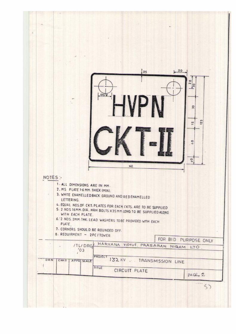


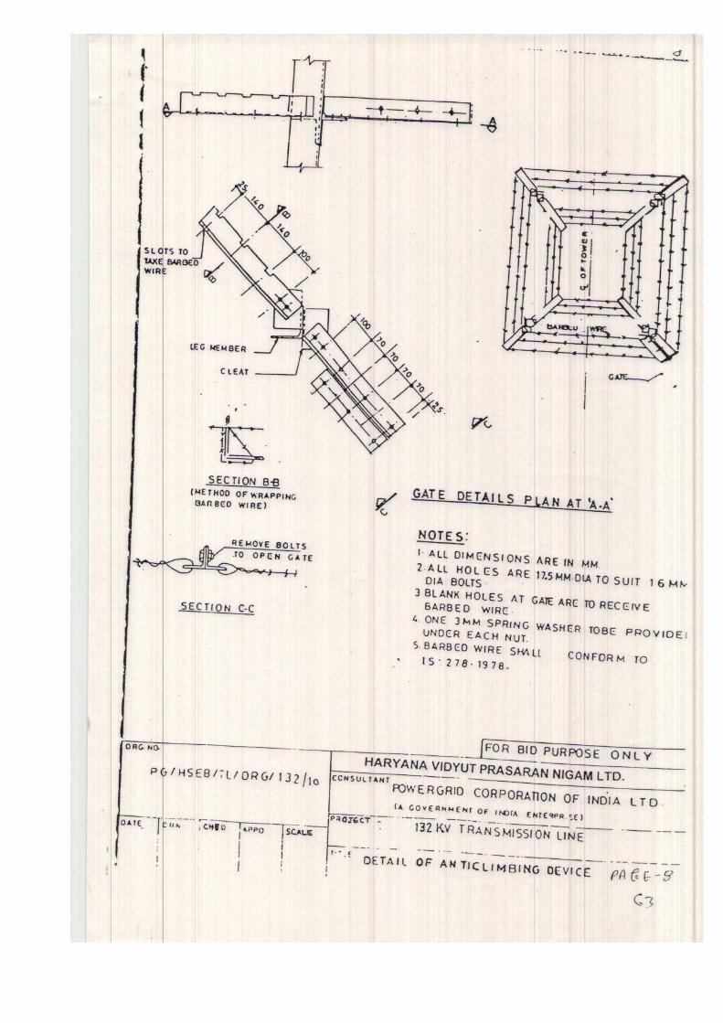

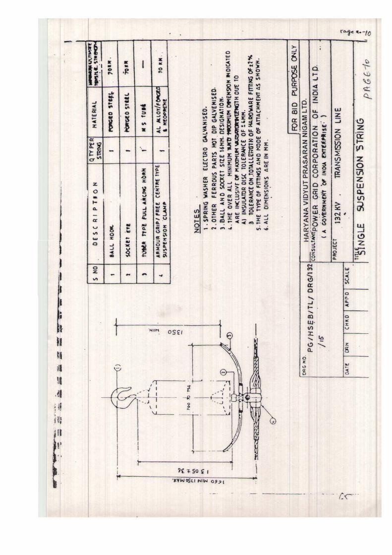


ANNEXURE-IB
ROUTE ALIGNMENT DETAILS
Sr. No.
Name of Line Tentative Length of Line
(Approx.)
1 Stringing of 2nd circuit of 132kV Ratia-Aharwan line with ACSR Panther
10.946 kms
2 LILO of existing one circuit of 132kV Ratia-Aharwan line
at 220kV S/Stn. Hukamawali on D/C towers with ACSR
Panther conductor
14.0 kms.
(DRAWINGS IN SEPARATE FOLIO)

SHEET-1 OF 2 BID DOCUMENT NO. –WB/G-10 (PKG. A)
LIST OF DRAWINGS FOR 132 KV LINE
Sr. No.
Name of Line Tentative route length (Approx.) in Kms.
1 LILO of existing one circuit of 132kV Ratia-Aharwan line at 220kV
S/Stn. Hukamawali on D/C towers with ACSR Panther conductor
14.0
LIST OF DRAWINGS FOR 132KV LINES
C) 132 KV D/C Tower (KRR Design) Drg.No./BOM 1 Line Diagram for DA type tower HTD/TT-706
2 Bill of material for DA type tower HVPN/BOM-32
3 Bill of material of stub for DA type tower HVPN/BOM-31
4 Bill of material of +3 mtr. extn. for DA type tower HVPN/BOM-33
5 Bill of material of +6 mtr. extn. for DA type tower HVPN/BOM-34
6 Line Diagram for DB type tower HTD/TT-707
7 Bill of material for DB type tower HVPN/BOM-41
8 Bill of material of stub for DB type tower HVPN/BOM-40
9 Bill of material of +3 mtr. extn. for DB type tower HVPN/BOM-42
10 Line Diagram for DC type tower HTD/TT-708
11 Bill of material for DC type tower HVPN/BOM-47
12 Bill of material of stub for DC type tower HVPN/BOM-46
13 Bill of material of +3 mtr. extn. for DC type tower HVPN/BOM-48
14 Line Diagram for DD type tower HTD/TT-709
15 Bill of material for DD type tower HVPN/BOM-53
16 Bill of material of stub for DD type tower HVPN/BOM-52

SHEET-2 OF 2 WBS G-10- A
LIST OF CIVIL FOUNDATIONS DRAWINGS
S. No DRAWING NO. DESCRIPTION
220 kV D/C (TATA DESIGN) TOWER FOUNDATION DETAILS:
1. HVPN-0041 DA, DB & DC Towers (0 to 6m ext.) – Dry Type
2. HVPN-0042 DD Towers (0 to 6m ext.) - Dry Type
3. HVPN-0043 DA, DB, DC & DD (0 to 6m ext.) - Wet Type
4. HVPN-0046 DA, DB, DC & DD (more than 6m ext.) - Dry Type
5. HVPN-0047 DA, DB, DC & DD (more than 6m ext.) - Wet Type
6. HVPN-0044 Gantry towers (AT-9B & AT-10)
7. HCD/TS-990 Well type foundation for 220kv D/C DA Type
(TATA DESIGN)
132 kV D/C (KRR DESIGN) TOWER FOUNDATION DETAILS:
1. HVPN-0051 DA Towers (0 to 6m ext.) KRR Design - Dry Type
2. HVPN-0052 DB Towers (0 to 6m ext.) KRR Design - DRY Type
3. HVPN-0053 DC Towers (0 to 6m ext.) KRR Design - DRY Type
4. HVPN-0054 DD Towers (0 to 6m ext.) KRR Design -DRY Type
5. HVPN-0055 DA Towers (0 to 6m ext.) KRR Design - WET Type
6. HVPN-0056 DB Towers (0 to 6m ext.) KRR Design -WET Type
7. HVPN-0057 DC Towers (0 to 6m ext.) KRR Design - WET Type
8. HVPN-0058 DDTowers (0 to 6m ext.) KRR Design - WET Type

SECTION-VI
PART-II

SECTION-VI (PART-II A) TECHNICAL SPECIFICATION CONTENTS
S. No Clause Page No.
1.0 General Information 1 2.0 Scope 1 3.0 Weights and measures 1 4.0 General Technical conditions 1 5.0 Technical Description 6 6.0 Tests and Standards 6
7.0 Guaranteed Technical Particulars 6 8.0 Technical Information 6

SECTION-VI
(PART- IIA) 1. General Technical Requirements 1.1 The material covered in this specification shall be used in 132 kV transmission
lines of HVPNL.
2. Scope: 2.1 The material shall be designed, manufactured and tested as per the requirements
specified. 2.2 The material covered under various packages shall be supplied complete in all
respect, including all component, fittings and accessories which are necessary or are usual for their efficient performance and satisfactory maintenance under the various operating and atmospheric conditions. Such parts shall deemed to be within the scope of the contract, whether specially included or not in the specifications or in the contract schedules. The bidder shall not eligible for any charges for such fittings etc.
3. Weights and measures
All weights and measures shall be in system international (SI) units. All fasteners shall be of metric size only.
4 General Technical Conditions
4.1 The following provisions shall supplement all the detailed technical specifications
and requirements brought out in the accompanying technical specifications. The bidder’s proposal shall be based on the use of equipment and materials complying fully with the requirements, specified herein.
4.2 Equipment performance Guarantee 4.2.1 The performance requirements of the items are detailed separately in this
specification. These guarantees shall supplement the general performance guarantee provisions covered under General Terms and Conditions of Contract in clause entitles ‘Guarantee”.
4.2.2 Liquidated damages for not meeting specified performance shall be assessed and
recovered from the manufacturer. Such liquidated damages shall be without any limitation whatsoever an shall be in addition to damage, if any payable under any other clause of conditions of contract.
4.3 Engineering Data
4.3.1 The furnishing of engineering data by the bidder shall be in accordance with the
appropriate schedule of specification. The review of these data by the HVPNL will cover only general conformance of the data to the specifications and drawings. This review by the HVPNL may not indicate a thorough review of all dimensions, quantities and details of the equipment, materials, any devices or items indicated or the accuracy of the information submitted. This review and/or approval by the HVPNL shall not be considered by the manufacturer, as limiting any of his responsibilities and liabilities for mistakes and deviations from the requirements, specified under these Specifications and documents.
Page-1

4.3.2 All engineering data submitted by the manufacturer after final process including review and approval by the HVPNL shall form part of the contract document and the entire works performed under these specifications shall be performed in strict conformity, unless otherwise expressly requested by the HVPNL in writing.
4.4 Drawings 4.4.1 All drawings submitted by the manufacturer including those submitted at the time of
bid shall be in sufficient detail to dictate the type, size, arrangement, dimensions, material description. Bill materials, weight of each component, break-up for packing and shipment, fixing arrangement required, the dimensions required for installation and any other information specifically requested in the specifications.
4.4.2 Each drawing submitted by the manufacturer shall be clearly marked with the name of
the HVPNL, the unit designation title, the specification number and the name of the project. All titles, notings, markings and writings on the drawing shall be in English. All the dimensions should be to the scale and in metric units.
4.4.3 The drawings submitted by the manufacturer shall be reviewed by the HVPNL as far
as practicable within four weeks and shall be modified by the manufacturer if any modifications and/or corrections are required by the HVPNL. The manufacturer shall incorporate such modifications and/or corrections and submit the final drawings for approval. Any delays arising out of failure by the manufacturer to rectify the drawings in good time shall not after the Contract completion date.
4.4.4 The drawings submitted for approval to the HVPNL shall be in quadruplicate. One
print of such drawings shall be returned to the manufacturer by the HVPNL marked “approved/approved with correction”. The manufacturer shall thereupon furnish the HVPNL additional print as stipulated in technical specification along with one reproducible in original in original of the drawings after incorporating all corrections.
4.4.5 Further work by the manufacturer shall be strictly in accordance with these drawings
and no deviation shall be permitted with out the written approval of the HVPNL, it so required.
4.4.6 All manufacturing and fabrication work in connection with the equipment/material prior
to the approval of the drawings shall be at the manufacturer’s risk. The manufacturer may make any changes in the design which are necessary to make the equipment conform to the provisions and intent of the contract and such changes will again be subject to approval by the HVPNL. Approval of manufacturer’s drawing or work by the HVPNL shall not relieve the manufacturer of any of his responsibilities and liabilities under the contract.
4.5 Manufacturing Schedule
The manufacturer shall submit to the HVPNL his manufacturing, testing and delivery schedules of various items within thirty (30) days from the date of the Letter of Award in accordance with the delivery requirements stipulated. Schedule shall also include the material and items purchased from outside manufacturers, if any.
Page-2

4.6 Reference Standards 4.6.1 The codes and/or standards referred to in specifications shall govern, in all cases
wherever such references are made. In case of a conflict between such Codes and/or Standards and the Specifications, latter shall govern. Such Codes and/or Standards, referred to shall mean the latest revisions, amendments/changes adopted and published by the relevant agencies. In case of any further conflict in this matter, the same shall be referred to the HVPNL whose decision shall be final and binding.
4.6.2 Other internationally acceptable standards which ensure equivalent or better
performance than those specified shall also be accepted. 4.7 Design Improvements 4.7.1 The HVPNL or the manufacturer may propose changes in the specification of the
equipment or quality thereof and if the parties agree upon any such changes, the specification shall be modified accordingly.
4.7.2 If any such agreed upon change is such that it affects the price and schedule of
completion, the parties shall agree in writing as to the extent of any change in the price and/or schedule of completion before the manufacturer proceeds with the change. Following such agreement, the provision thereof, be deemed to have been amended accordingly.
4.8 HVPNL SUPERVISION 4.8.1 To eliminate delays and avoid disputes and litigation if is agreed between the parties
to the contract that all matters and questions shall be referred to the HVPNL and his decision shall be final.
4.8.2 The manufacturing of the product shall be performed under the direction and
supervision of the HVPNL. The scope of the duties of the HVPNL, pursuant to the contract, will include but not be limited to the following: -
a) Interpretation of all the terms and conditions of these documents and specifications. b) Review and interpretation of all the manufacturer’s drawings, engineering data etc. c) Witness or authorize his representative to witness tests at the manufacturer’s works or
at site, or at any place where work is performed data etc. d) Inspect accept or reject any equipment, material and work under the contract. e) Issue certificate of acceptance and/or progressive payment and final payment
certificate. f) Review and suggest modification and improvement in completion schedule from time
to time; and g) Supervision the Quality Assurance programme implementation at all stages of the
works. Page-3

4.9 Inspection, Testing & Inspection Certificate 4.9.1 The HVPNL, his duly authorized representative and/or outside inspection agency
acting on behalf of the HVPNL shall have at all reasonable times access to the manufacturer’s premises or works and shall have the power at all reasonable times to inspect and examine the materials and workmanship of the product during its manufacture and if part of the product is being manufactured or assembled at other premises or works, the manufacturer shall obtain from the HVPNL and/or his duly authorized representative permission to inspect as if the equipment/materials were manufactured or assembled on the manufacturer’s own premises or works.
4.9.2 The manufacturer shall give the HVPNL/inspector fifteen (15) days written notice of
any material being ready for testing. Such tests shall be to the manufacture’s account except for the expenses of the inspector. The HVPNL/inspector, unless witnessing of the tests is virtually waived, will attend such tests within fifteen (15) days of the date of which the equipment is notified as being ready for test/inspection or on a mutually agreed date, failing which the manufacturer may proceed and he shall forthwith forward to the inspector duly certified copies of tests triplicate.
4.9.3 The HVPNL/ inspector shall, within fifteen (15) days from the date of inspector as
defined herein give notice in writing to the manufacturer, of any objection to any drawings and all or any equipment and workmanship which in his opinion is not in accordance with the contract. The manufacturer shall give due consideration to such objections and shall make the modifications that may be necessary to meet the said objections.
4.9.4 When the factory tests have been completed at the manufacturer’s or sub-
manufacturer’s work, the HVPNL/inspector shall issue a certificate to this effect within fifteen (15) days after completion of tests but if the tests are not witnessed by the HVPNL/inspector, the certificate shall be issued within fifteen (15) days of receipt of the manufacturer’s test certificate by the HVPNL/inspector. The completion of these tests of the issue of the certificate shall not bind the HVPNL to accept the equipment should it, on further tests after erection, be found not to comply with the contract.
4.9.5 In all cases where the contract provides for tests whether at the premises or works of
the manufacturer or of any sub-manufacturer, the manufacturer except where otherwise specified shall provide free of charge such item as labour, materials, electricity, fuel, water, stores, apparatus and instruments as may be reasonably demanded by the HVPNL/inspector or his authorized representative to carry out effectively such tests of the equipment in accordance with the contract and shall give facilities to the HVPNL/inspector or his authorized representative to accomplish testing.
4.9.6 The inspection by HVPNL and issue of inspection certificate thereon shall in no way
limit the liabilities and responsibilities of the manufacturer in respect of the agreed Quality Assurance Programme forming a part of the contract.
Page-4

5. Technical Description
The technical description of conductor, earthwire, insulators, hardware fittings & conductor and earthwire accessories shall be as specified in part-II of this technical specification.
6. Tests and Standards 6.1 The tests and standards for conductor, earthwire, insulators, hardware fittings &
conductor and earthwire accessories are specified in part-II B, IIC & II D of this Technical Specification.
7 Guaranteed Technical Particulars
The Guaranteed Technical Particular of the various items covered under this specification shall be furnished by the bidders in one original and four (4) copies in the prescribed schedules of the specifications. The bidder shall also furnish any other schedule informations as in their opinion is needed to give fully description and details to judge the item (s) offered by them.
8 Technical Information
Electrical system data for 132 kV line a) Nominal voltage 132KV b) Maximum system voltage 145 KV c) Bil (Impulse) 650 KV (peak) d) Power frequency withstand voltage (wet) 275KV (rms)
Line data
Conductor
a) Name ACSR ‘Panther’ b) Strands and wire diameter
i) Aluminum 30/3.00 mm ii) Steel 7/3.00 mm
c) Conductor per phase One d) Inter phase spacing Vertical 4900 mm(min.) Horizontal 8400 mm (Min.)
Page-5

e) Configuration D/C line Vertical S/C line Triangular
f) Overall diameter 21.00 mm g) Weight 974 kg/km h) Minimum ultimate tensile strength 89.67 KN B) Galvanised Steel Earthwire
a) Size (strands & wire diameter) 7/3.15 mm b) Overall diameter 9.45 mm c) Standard weight 428 kg/km d) Location of earthwire One continuous earthwire to run
horizontally on top of the towers and conductors.
e) Minimum ultimate tensile strength 57kN
f) Ruling Design span 300 Meters g) Wind Zone (As per IS: 875:1987) 4
Page-6

SECTION-VI (PART-II B) TECHNICAL SPECIFICATION CONTENTS
S. No Clause Page No.
1. Technical Description of Conductor for ACSR Panther lines 1 2 Technical Description of Earth wire 9 5. Tests and Standards 11 6. Annexure-A 20

SECTION-VI
(PART-IIB)
TECHNICAL SPECIFICATION
TECHNICAL SPECIFICATION OF CONDUCTOR 1. A) DETAIL OF CONDUCTOR 1.1.1 The conductor shall generally conform to IS: 398-1998 excepts where otherwise
specified herein. Conductor shall only be accepted from those who have got the ISI certification or equivalent internationally recognized Standard and documentary proof for having such certification shall be submitted with the Bid.
1.1.2 The conductor shall be ACSR ‘Panther’ and the details of the conductor are
tabulated below:
a) Stranding and wire diameter : 30/3.00 mm Aluminium +7/3.00 mm steel b) Number of Strands : Core : 1 1st layer : 6 2nd layer : 12 3rd layer : 18 c) Total sectional area Aluminium : 212.1 sq. mm d) Total sectional area : 261.5 sq.mm e) Overall diameter : 21.0 mm f) Approximate weight : 974Kg/km g) Calculated DC resistance at : 0.140 ohm/km 20 deg. Centigrade (Max.) h) Minimum UTS : 89.67 kN i) Direction of lay of outer : Right hand j) Modulus of elasticity : 8158 (Kg/sq. mm) k) Co-efficient of linear expansion (per oC) : 17.8x10⁻⁶ Page-1

1.1.3 a) The details of Aluminium strands are as follows:
i) Minimum breaking load of strand before stranding : 1.17 KN ii) Minimum breaking load of strand after stranding : 1.11 KN iii) Maximum D.C. resistance of strand at 20 deg. : 4.107 Centigrade Ohms/km b) The details of steel strand are as follows: i) Minimum breaking load of strand before stranding : 9.29 KN ii) Minimum breading load of strand after stranding : 8.85 KN
1.2 Workmanship: 1.2.1 All the aluminium and steel strands shall be smooth, uniform and free from all
imperfections, such as spills and splits, diemarks, scratches, abrasions and kinks after drawing and also after stranding.
1.2.2 The finished conductor shall have a smooth surface without any surface cuts,
abrasions, scuff marks and shall be free from dirt, grit, etc. 1.2.3 The steel strands shall be hot dip galvanized and shall have a minimum zinc coating
of 250g/m2 after stranding. The zinc coating shall be smooth, continuous, of uniform thickness, free from imperfections and shall withstand a minimum of two and one half dips in the standard preece test. The steel wire rods shall be of such quality and purity that, when drawn to the size of the strands specified and coated with zinc, the finished strands and the individual wires shall be of uniform quality and have the same properties and characteristics as prescribed in IEC:888-1987.
1.2.4 The steel strands shall be preformed and postformed in order to prevent spreading of
strands in the event of cutting of composite core wire. Care shall be taken to avoid damages to galvanization during preforming and postforming operations.
1.3 Joints in Wires: 1.3.1 Aluminium Wires
No joints shall be permitted in the individual wires in the outer most layer of the finished conductor. However, joints in the 12 wire inner layer of the conductor unavoidably broken during stranding provided such breaks are not associated with either inherently defective wire or with the use of short lengths of aluminium wires. Such joints shall not be more than four (4) per conductor lengths. These joist shall be made by cold pressure butt-welding and shall be such that no two such joints are within 15 metres of each other in the complete stranded conductor.
1.3.2 Steel Wires
There shall be no joint of any kind in the finished wire entering into the manufacture of the strand nor strand joint or strand splices in any length of the complete stranded steel core of the conductor. Page-2

1.4 Tolerances
The manufacturing tolerances to the extent of following limits only shall be permitted in the diameter of individual Aluminium and steel strands and lay-ratio of the conductor: a) Diameter of Aluminium & steel Strands
Nominal Maximum Minimum
Aluminium 3.0 mm 3.03 mm 2.97 mm Steel 3.0 mm 3.06 mm 2.94 mm
b) Lay ratio of Conductor
Max. Min. 6 Wire layer 28 (Steel) 16 12 wire layer 16 (Al.) 10 18 wire layer 14 (Al.) 10 1.5 Materials 1.5.1 The Aluminium strands shall be hard drawn from electrolytic aluminum rods having a
purity of not less than 99.5% and a copper content not exceeding 0.04%. They shall have the same properties and characteristics as prescribed in IEC:889-1987.
1.5.2 The steel wire strands shall be drawn from high carbon steel wire rods produced by
either the acid or basic open hearth process, the electric furnace process, or the basic oxygen process and shall conform to the following requirements as to the chemical composition:
Element % composition Carbon 0.50 to 0.85 Manganese 0.50 to 1.10 Phosphorus Not more than 0.035 Sulphur Not more than 0.045 Silicon 0.10 to 0.35 The steel wire stands shall have the same properties and characteristics as proscribed for regular strength steel wire in IEC:888-1987..
1.5.3 The zinc used for galvanizing shall be electrolytic high grade Zinc of 99.95% purity. It
shall conform to and satisfy all the requirements of IS:209. Page-3

1.6 Standard Length 1.6.1 The Standard Length of the conductor shall be 1500 meters. Bidder shall indicate the
standard length of the conductor to be offered by them. A tolerance of +/- 5% on the standard length offered by the Bidder shall be permitted. All lengths outside this limit of tolerance shall be treated as random lengths.
1.6.2 Random lengths will be accepted provided no length is less than 70% of the standard
length and total quantity of such random lengths shall not be more than 10% of the quantity ordered. When one number random length has been manufactured at any time, five (5) more individual lengths, each equivalent to the above random length with a tolerance of +/- 5% shall also be manufactured and all the above six random lengths shall be despatched in the same shipment. At any point, the cumulative quantity supplied including such random lengths shall not be more than 12.5% of the total cumulative quantity supplied including such random lengths. However, the last 20% of the quantity ordered shall be supplied only in standard lengths as specified.
1.6.3 Bidder shall also indicate the maximum single length, above the standard length, he
can manufacture in the guaranteed technical particulars of offer. This is required for special stretches like river crossing etc. The HVPNL reserves the right to place orders for the above lengths on the same terms and conditions applicable for the standard lengths during pendency of the contract.
2. Technical Description of Earthwire .
2.1 Details of Earthwire 2.1.1 The galvanized steel earthwire shall generally conform to the specification of ACSR
core wire as mentioned in IS:398 (part-II)-1976 except where otherwise specified herein.
2.1.2 The details of the earthwire are tabulated below:
a) Stranding and wire diameter : 7/3.15 mm steel b) Number of Strands : Steel core : 1 Outer steel layer : 6 c) Total sectional area : 54.55 sq.mm d) Overall diameter : 9.45 mm e) Approximate weight : 428Kg/km f) Calculated DC resistance at : 3.375 ohm/km 20 deg. Centigrade g) Minimum ultimate tensile : 56 kN
strength h) Direction of lay of outer layer : Right hand i) Minimum tensile strength : 110 kgf/mm. sq.
Page-4

2.2 Workmanship 2.2.1 All steel strands shall be smooth, uniform and free from all imperfection, such as spills
and splits, diemarks, scratches, abrasions and kinks after drawing and also after stranding.
2.1.2 The finished material shall have minimum brittleness as it will be subjected to
appreciable vibration while in use. 2.1.3 The steel strands shall be hot dip galvanized and shall have a minimum zinc coating
of 240 g/m2 after stranding. The zinc coating shall be smooth, continuous, of uniform thickness, free from imperfections and shall withstand three and a half dips after stranding in standard preece test. The steel wire rods shall be of such quality and purity that, when drawn to the size of the strands specified and coated with the finished strands shall be of uniform quality and have the same properties and characteristics as prescribed in ASTM designation B498-74.
2.1.4 The steel strands shall be preformed and postformed in order to prevent spreading of
strands while cutting of composite earthwire. Care shall be taken to avoid damages to galvanization during performing and postforming operations.
2.1.5 To avoid susceptibility towards wet storage stains (white rust), the finished material
shall be provided with a protective coating of boiled linseed oil. 2.3 Joints in Wires
There shall be no joint of any kind in the finished steel wire strand entering into manufacture of the earthwire. There shall be no strand joints or strand splice any length of the complete stranded earthwire.
2.4 Tolerances The manufacturing tolerance to the extent of the following limits only shall permitted in
the diameter of the individual steel strands and lay length of earthwire.
Standard Maximum Minimum
Diameter 3.15 mm 3.20 mm 3.10 mm Lay length 160 mm 175 mm 145 mm 2.5 Materials 2.5.1 Steel
The steel wire strands shall be drawn from high carbon steel rods and shall conform to the following requirements as to the chemical composition:
Element % composition Carbon Not more than 0.55 Manganese 0.4 to 0.9 Phosphorus Not more than 0.04 Sulphur Not more than 0.04 Silicon 0.15 to 0.35 Page-5

2.5.2 Zinc
The zinc used for galvanizing shall be electrolytic high grade zinc of 99.95% purity. It shall conform to and satisfy all the requirements of IS:209/1979.
2.6 Standard Length 2.6.1 The Standard Length of the earthwire shall be 2000 meters. The tolerance on length
shall be +/- 5% on the standard length. 2.6.2 Random lengths will be accepted provided no length is less than 70% of the standard
length and total quantity of random lengths is not be more than 10% percent of the total quantity in each shipment.
3. Tests and standards 3.1 Tests
3.1.1 The following acceptance and routine tests and tests during manufacture shall be
carried out on the conductor and earthwire. For the purpose of this clause, the following shall apply.
3.1.2 Acceptance tests shall mean those tests which are to be carried out on samples taken
from each lot offered for pre-despatch inspection, for the purpose of acceptance of that lot.
3.1.3 Routine tests shall mean those tests, which are to be carried out on each strand/
spool/length of the conductor and earthwire to check requirements which are likely to vary during production.
3.1.4 Tests during manufacture shall mean those tests, which are to be carried out during the
process of manufacture and end inspection by the manufacture to ensure the desired quality of the end product to be supplied by him.
3.1.5 For all acceptance tests, the acceptance values shall be the values guaranteed by the
bidder in the guaranteed technical particulars of his proposal or the acceptance value specified in this specification, whichever is more stringent for that particular test.
3.2 Type Tests
3.2.1 The equipment should be offered type tested. Test reports should not be more
than seven years old reckoned from the date of bid opening in respect of all the tests
carried out in accredited laboratories ( based on ISO/IEC) by a reputed accreditatic
body or witnessed by HVPNL or another electric power utility and be submitted by the
successful Bidder to HVPNL for approval as per schedule given in Bar chart.
a) Surface condition test b) Test for ultimate breaking load on stranded conductor c) Stress-strain test d) Measurement of diameter of individual aluminium and steel wires. e) Measurement of lay ratio. f) Breaking load of individual wires. g) Ductility test h) Wrapping test i) Resistance test and j) Galvanizing test
Page-6

3.2.2 Acceptance Tests
a) Visual and dimensional check on drum ) ) Annexure-A
b) Visual check for joints scratches etc. ) and lengths of conductor by rewinding ) )
c) Dimensional check on steel and ) Aluminium strands )
) d) Galvanising test on steel strands ) Annexure-A
) e) Torsion and elongation test )
On steel strands ) )
f) Check for lay-ratios of various layers ) Annexure-A
g) Breaking load test on steel and ) aluminum strands )
) h) Wrap test on steel and aluminum ) IS:398 (part-II)
strands ) ) i) DC resistance test on aluminium strands )
j) UTS Test on welded joint of strands ) Annexure-A Note: All the tests except (j) shall be carried out on Aluminium and steel strands after stranding only.
3.2.3 Acceptance Tests on Earthwire
a) Visual and dimensional check on drum ) )
b) Visual check for joints scratches etc. ) and lengths of Earthwire by rewinding ) )
c) Dimensional check ) Annexure-A )
d) Lay length check ) ) e) Galvanising test )
) f) Torsion test )
g) Elongation test ) IS:398 (part-II)-1976 )
h) Wrap test ) )
i) DC resistance test ) )
j) Breaking load test ) Page-7

k) Chemical analysis of steel ) IS:398 (part-II)-1976 3.3 Routine Tests 3.3.1 Routine tests on Conductor
a) Check to ensure that the joints are as per specification.
b) Check that there are no cuts, fins etc. on the strands.
c) Check that drums are as per specification.
d) All acceptance test as mentioned above to be carried out on each coil. 3.3.2 Routine tests on Earthwire
a) Check for correctness of stranding.
b) Check that there are no cuts, fins etc. on the strands.
c) Check that drums are as per specification. 3.4 Tests during manufacture. 3.4.1 Tests during manufacture on conductor
a) Chemical analysis of zinc ) used for galvanizing ) Annexure-A )
b) Chemical analysis of aluminium ) used for making aluminium strands ) Annexure-A
3.4.2 Tests during manufacture Earthwire.
a) Chemical analysis of zinc ) used for galvanizing ) Annexure-A
) b) Chemical analysis of steel )
3.5 Testing Expenses
The entire cost of testing for the acceptance and routine tests and tests during manufacture specified herein shall be treated as included in the quoted unit price except for the expenses of the inspector/ HVPNL representative.
3.6 Addition Tests
The HVPNL reserves the right of having at his own expenses any other test (s) of reasonable nature carried out at Manufacturer’s premises, at site, or in any other place in addition to the aforesaid type, acceptance and routine tests to satisfy himself that materials comply with the specifications. Pge-8
3.7 Test Reports 3.7.1 Record of routine test reports shall be maintained by the manufacturer at his works for
periodic inspection by the HVPNL representative. 3.7.2 Test certificates of tests during manufacture shall be maintained by the manufacturer.
These shall be produced for verification as and when desired by the HVPNL. 3.8 Inspection
3.8.1 The HVPNL representative shall at all times be entitled to have access to the works
and all places of manufacture, where conductor shall be manufactured and representative shall have full facilities for unrestricted inspection of the manufacturer works, raw materials and process of manufacture for conducting necessary tests as detailed herein.
3.8.2 The manufacturer shall keep the HVPNL informed in advance of the time of starting
and of the progress of manufacture of conductor in its various stages so that arrangements can be made for inspection.
3.8.3 No material shall be despatched from its point of manufacture before it has been
satisfactorily inspected and tested, unless the inspection is waived off by the HVPNL in writing. In the later case also the conductor shall be despatched only after satisfactory testing for all tests specified herein have been completed.
3.8.4 The acceptance of any quantity of material shall in no way relieve the manufacturer of
any of his responsibilities for meeting all requirements of the specification, and shall not prevent subsequent rejection if such material is later found to be defective.
3.9 Test Facilities
3.9.1 The following additional test facilities shall be available at the manufacturer’s works:
a) Calibration of various testing and measuring equipment including tensile testing
machine, resistance measurement facilities, burette, thermometer, barometer etc. b) Standard resistance for calibration of resistance bridges. c) Finished conductor/Earthwire shall be checked for length verification and surface
finish on separate rewinding machine at reduced speed (variable from 8 to 16 meters per minute). The rewinding facilities shall have appropriate clutch system and free of vibrations, jerks etc. with traverse laying facilities.
3.10 Packing for conductor 3.10.1 The Conductor and earthwire shall be supplied in non-returnable, strong, wooden/
steel drums provided with lagging of adequate strength, constructed to protect the conductor against all damage and displacement during transit, storage and subsequent handing and stringing operations in the field. The manufacturer shall be responsible for any loss or damage during transportation, handling and storage due to improper packing. The drums shall generally conform to IS: 1778-1980, except as otherwise specified hereinafter.
Page-9

3.10.2 The drums shall be suitable for wheel mounting and for letting off the
Conductor/earthwire under a minimum controlled tension of the order of 5 KN. 3.10.3 The general outline of the drum for earthwire shall be as per annexed drawing.
The bidder should submit their proposed drawings alongwith the bid. 3.10.4 For conductor, one standard length and for earthwire two standard lengths shall
be wound on each drum. 3.10.5 For Earthwire, each strand shall be individually welded to prevent parting of two
lengths at a tension less than 15 kN. The two ends where the first length finishes and the second length starts, shall be clearly marked with adhesive tape and no weld should be present outside these marks. The length between the two marks shall be treated as scrap and will not be taken into account for measurement purposes.
3.10.6 All wooden components shall be manufactured out of seasoned soft wood free
from defects that may materially weaken the component parts of the drums. Preservative treatment shall be applied to the entire drum with preservatives of a quality, which is not harmful to the conductor and earthwire.
3.10.7 The flanges shall be of two ply construction with each ply at right angles to the
adjacent ply and nailed together. The nails shall be driven from the inside face flange, punched and then clenched on the outer face. The thickness of each ply shall not very by more than 3 mm from that indicated in the figure. There shall be at least 3 nails per plank of ply with maximum nail spacing of 75 mm. Where a slot is cut in the flange to receive the inner end of the conductor, the entrance shall be in line with the periphery of the barrel.
3.10.8 The wooden battens used for making the barrel of the conductor shall be of
segmental type. These shall be nailed to the barrel supports with at least two nails. The battens shall be closely butted and shall provide a round barrel with smooth external surface. The edges of the battens shall be rounded or chamfered to avoid damage to the conductor and earthwire.
3.10.9 Barrel studs shall be used for the construction of drums. The flanges shall be
holed and the barrel supports slotted to receive them. The barrel studs shall be threaded over a length on either end, sufficient to accommodate washers, spindle plates and nuts for fixing flanges at the required spacing.
3.10.10 Normally, the nuts on the studs shall stand protruded of the flanges. All the Niles
used on the inner surface of the flanges and the drum barrel shall be counter sunk. The ends of barrel shall generally be flushed with the top of the nuts.
3.10.11 The inner cheek of the flanges and drum barrel surface shall be painted with
bitumen based paint. Page-10

3.10.12 Before reeling, card board or double corrugated or thick bituminised waterproof bamboo paper shall be secured to the drum barrel and inside of flanges of the drum by means of a suitable commercial adhesive material. After reeling the conductor and earthwire, the exposed surface of the outer layer of conductor/earthwire shall be wrapped with water proof thick bituminised bamboo paper to preserve the conductor/earthwire from dirt, grit and damage during transport and handling.
3.10.13 A minimum space of 75 mm for conductor and 50 mm for earthwire shall be
provided between the inner surface of the external protective lagging and outer layer of the conductor/earthwire.
3.10.14 Each batten shall be securely nailed across grains as far as possible to the
flange, edges with at least 2 nails per end. The length of the nails shall not be less than twice the thickness of the battens. The nails shall not protrude above the general surface and shall not have exposed sharp, edges or allow the battens to be released due to corrosion.
3.10.15 The nuts on the barrel studs shall be tack welded on the one side in order to fully
secure them. On the second end, a spring washer shall be used. 3.10.16 Outside the protective lagging, there shall be minimum of two binder consisting of
hoop iron/galvanised steel wire. Each protective lagging shall have two recesses to accommodate the binders.
3.10.17 The conductor ends shall be properly sealed on the side of one of the flanges to
avoid loosening of the conductor layers during transit and handling.
3.11 Marking
Each drum shall have the following information stenciled on it in indelible ink alongwith other essential data:
a) Contract / Award letter number.
b) Name and address of consignee. c) Manufacturer’s name and address. d) Drum number. e) Size of conductor/earthwire. f) Length of conductor/earthwire in meters.
g) Gross weight of drum with conductor/earthwire. h) Gross weight of drum without lagging. i) Weight of empty drum with lagging.
j) Bevel diameter at three locations and an arrow marking at the location of
measurement.
k) Number of turns in the outer most layer.
Page-11

l) Arrow marking for unwinding.
m) Position of the conductor/earthwire ends.
n) Distance between outer most layer of conductor and the inner surface of lagging.
o) The conductor drum should bear ISI Monogram or equivalent internationally
recognized Monogram. 3.12 Verification of conductor and earthwire length.
The HVPNL reserves the right to verify the length of conductor and earthwire after unreeling at least ten (10) percent of the drums in a lot offered for inspection.
3.13 Standards
The conductor/earthwire shall conform to the following Indian / International standards, which shall mean latest revisions, amendments /changes adopted and published, unless otherwise specified herein before. International and internationally recognized standards to which these standards generally correspond are also listed below: ----------------------------------------------------------------------------------------------------------- Sr. Indian Title International No Standard Standards ----------------------------------------------------------------------------------------------------------- 1. IS: 209-1979 Specification for Zinc BS: 3436-1986
2 IS: 398-1982 Specification for aluminium conductors for overhead transmission purposes
BS: 215-1970 IEC:1089
3 IS:398-1982 Part (II)
Aluminum conductor galvanized steel reinforced
BS: 215-1970
4 IS:1778-1980
Reels and drums for bare conductors
BS:1559-1949
5 IS:1521-1972 Method of tensile testing of steel wire
ISO:R8901959
6 IS:2629-1985 Recommended practice for hot dip galvanizing of iron and steel
7 IS:2633-1992 Method of testing uniformity of coating on zinc coated articles
8 IS:4826-1992 Galvanised coating on round steel wires
ASTM A472-729 BS: 443-1969
9 IS:6745-1990 Methods of determination of weight of zinc coating of zinc coated iron and steel articles
BS:433-1969
10 Zinc coated aluminium wire for overhead line conductor
IEC 888-1987
11 Hard drawn aluminium wire for overhead line conductor
IEC 889-1987
Page-12
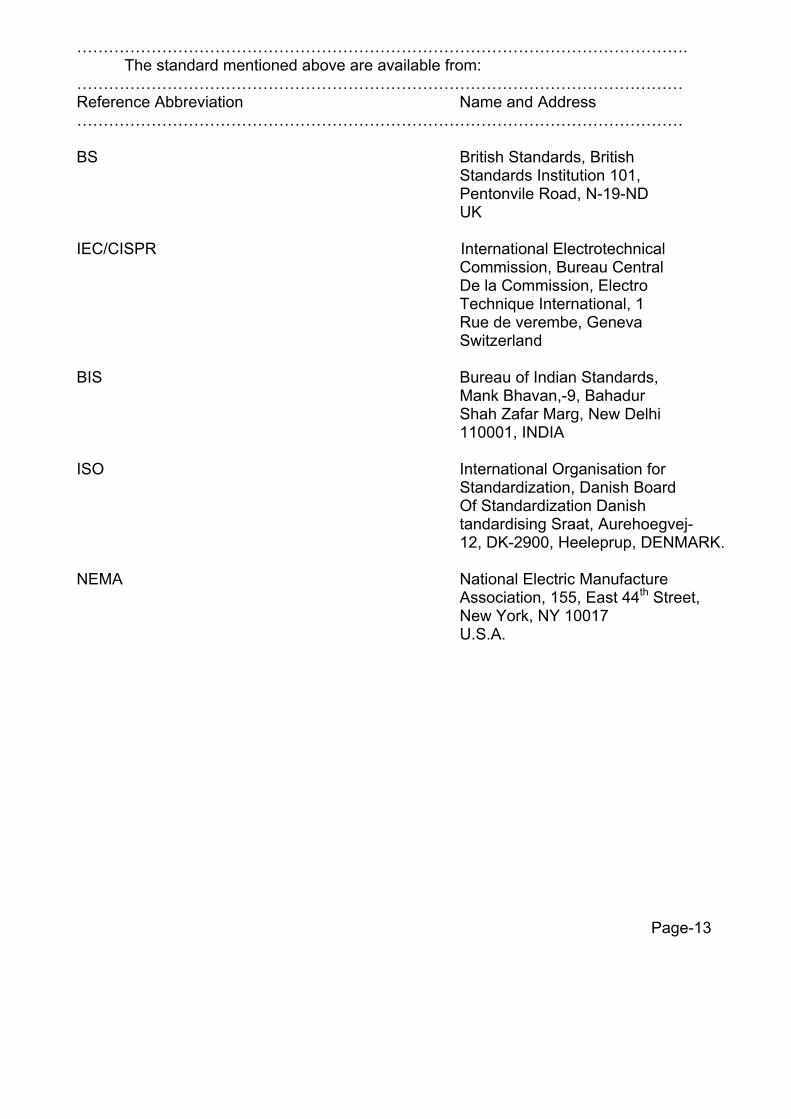
……………………………………………………………………………………………………. The standard mentioned above are available from: …………………………………………………………………………………………………… Reference Abbreviation Name and Address …………………………………………………………………………………………………… BS British Standards, British Standards Institution 101, Pentonvile Road, N-19-ND UK IEC/CISPR International Electrotechnical Commission, Bureau Central De la Commission, Electro Technique International, 1 Rue de verembe, Geneva Switzerland BIS Bureau of Indian Standards, Mank Bhavan,-9, Bahadur Shah Zafar Marg, New Delhi 110001, INDIA ISO International Organisation for Standardization, Danish Board Of Standardization Danish
tandardising Sraat, Aurehoegvej- 12, DK-2900, Heeleprup, DENMARK.
NEMA National Electric Manufacture Association, 155, East 44th Street, New York, NY 10017 U.S.A. Page-13

ANNEXURE-A
1. Tests on Conductor
1.1 Surface condition & UTS test on stranded Conductor
Circles perpendicular to the axis of the conductor shall be marked at two places on a sample of conductor of minimum 5m length suitably fixed by appropriate fittings on a tensile testing machine. The load shall be increased at a steady rate upto 50% of UTS and held for one minute. The circles drawn shall not be distorted due to relative movement of strands. Thereafter the load shall be increased at steady rate of 100% of UTS and held for one minute. The conductor sample shall not fail during this period. The applied load shall then be increased until the failing load is reached and the value recorded.
1.2 D.C Resistance test on stranded conductor
On a conductor sample of minimum 5 m length two contact-clamps shall be fixed with a pre-determined bolt torque. The resistance shall be measured by a Kelvin double bridge by placing the clamps initially zero metre and subsequently one metre apart. The test shall be repeated at least five times and the average value recorded. The value obtained shall be corrected to the value at 20o C. The resistance corrected at 20o C shall conform to the requirement of this specification.
1.3 Chemical Analysis of Aluminium and Steel
Samples taken from the aluminium and steel ingots/coils/strands shall be chemically/spectrographically analysed. The shall be in conformity to the requirements stated in this specification.
1.4 Chemical Analysis of Zinc
Samples taken from the zinc ingots shall be chemically/spectrographically analysed. The same shall be in conformity requirements stated in the specification.
1.5 Visual and Dimensional Check on Drums
The drums shall be visually and dimensionally checked to ensure that they conform to the requirements of this specification.
1.6 Visual Check for Joints, Scratches etc.
Conductor drums shall be rewound in the presence of the HVPNL. The HVPNL shall visually check for scratches, joints etc. and that the conductor generally conform to the requirements of this specification.
1.7 Dimensional check on strands
The individual strands shall be dimensionally checked to ensure that they conform to the requirement of this specification. Page-14

1.8 Check for Lay-ratios of Various Layers
The Lay-ratios of various layers shall be checked to ensure that they conform to the requirements of this specification.
1.9 Breaking load test on welded Aluminium strands
Two Aluminium wire shall be welded as per the approved quality plan and shall be subjected to tensile load. The welded joint of the wire shall be able to withstand a minimum breaking load of the individual strand guaranteed by the manufacturer.
1.10 Galvanising test
The Test procedure shall be as specified in IS:4826. The material shall conform to the requirements of this specification. The adherence of zinc shall be checked by wrapping around a mandrel four times the diameter of steel wire.
1.11 Torsion an Elongation tests on steel strands.
The test procedure shall be as specified in IS: 13.6.1 and 13.6.2 of IS:398 part-5. In the torsion test, the number of complete twists before fracture shall not be less than 18 on a length equal to 100 times the standard diameter of the strand before stranding, and should not be less than 16 after stranding. The case test sample length is less or mode than 100 times the stranded diameter of the strand the minimum number of twists shall be proportioned to the length with fractional numbers rounded off to next higher whole number. In the elongation test the elongation of the strand shall not be less than 4% for a gauge length of 200mm.
2. Tests on earthwire
2.1 UTS test
Circles perpendicular to the axis of the earthwire shall be marked at two places on a sample of earthwire of minimum 5 m length suitably compressed with dead end clamps at either end. The load shall be increased at a steady rate upto 50% of UTS and held for one minute. The circles drawn shall not be distorted due to relative movement of strands. Thereafter the load shall be increased at steady rate to 100% of UTS and held for one minute. The earthwire sample shall not fail during this period. The applied load shall then be increased until the failing load is reached and the value recorded.
2.2 D.C Resistance Test
On a earthwire sample of minimum 5 m length two contact- clamps shall be fixed will a pre-determined bolt torque. The resistance shall be measured by a Kelvin double bridge by placing the clamps initially zero metre and subsequently one metre. The test shall be repeated at least five times and the average value recorded. The value obtained shall be corrected to the value at 20o C. The resistance corrected at 20o C shall conform to the requirements of this specification. Page-15
2.3 Chemical Analysis of zinc
Samples taken from the zinc ingots shall be chemically/spectrographically analysis. The same shall be in conformity to the requirements stated in the specification.
2.4 Chemical Analysis of steel
Sample taken from the steel ingots/coils/strands shall be chemically/specigraphically analysed. The same shall be in conformity to the requirements stated in this specification.
2.5 Visual and Dimensional Check on Drum
The drum shall be visually and dimensionally checked to ensure that they conform to the requirements of this specification.
2.6 Visual Check for joints, Scratches etc. and length of earthwire
Ten percent drums from each lot shall be rewound in the presence of the HVPNL. The HVPNL shall visually check for scratches, joints etc. and see that the earthwire generally conforms to the requirements of this specification. The length of earthwire wound on the drum shall be measured with the help of counter meter during rewinding.
2.7 Dimensional Check
The individual strands shall be dimensionally checked to ensure that they conform to the requirements of this specification.
2.8 Lay length check
The lay length shall be checked to ensure that they conform to the requirements this specification.
2.9 Galvanising Test
The test procedure shall be as specified in IS:4826-1968. The material shall conform to the requirements of this specification. The adherence of zinc shall be checked by wrapping around a mandrel four times the diameter of steel wire.
2.10 Torsion Test
The minimum number of twists which a single steel strand shall withstand during torsion test shall be eighteen for a length equal to100 times the standard diameter of the strand. In case test sample length is less or more than 100 times the stranded diameter of the strand, the minimum number of twists will be proportioned to the length and if number comes in the fraction then it will be rounded off to next higher whole number.
Page-16
(PART-II C) TECHNICAL SPECIFICATION CONTENTS
S. No Clause Page No.
1. Technical Description of Anti-fog Disc Insulators 1 2. Tests and Standards 8 3. Annexure-A 14 4. 132 kV Post Insulators 18
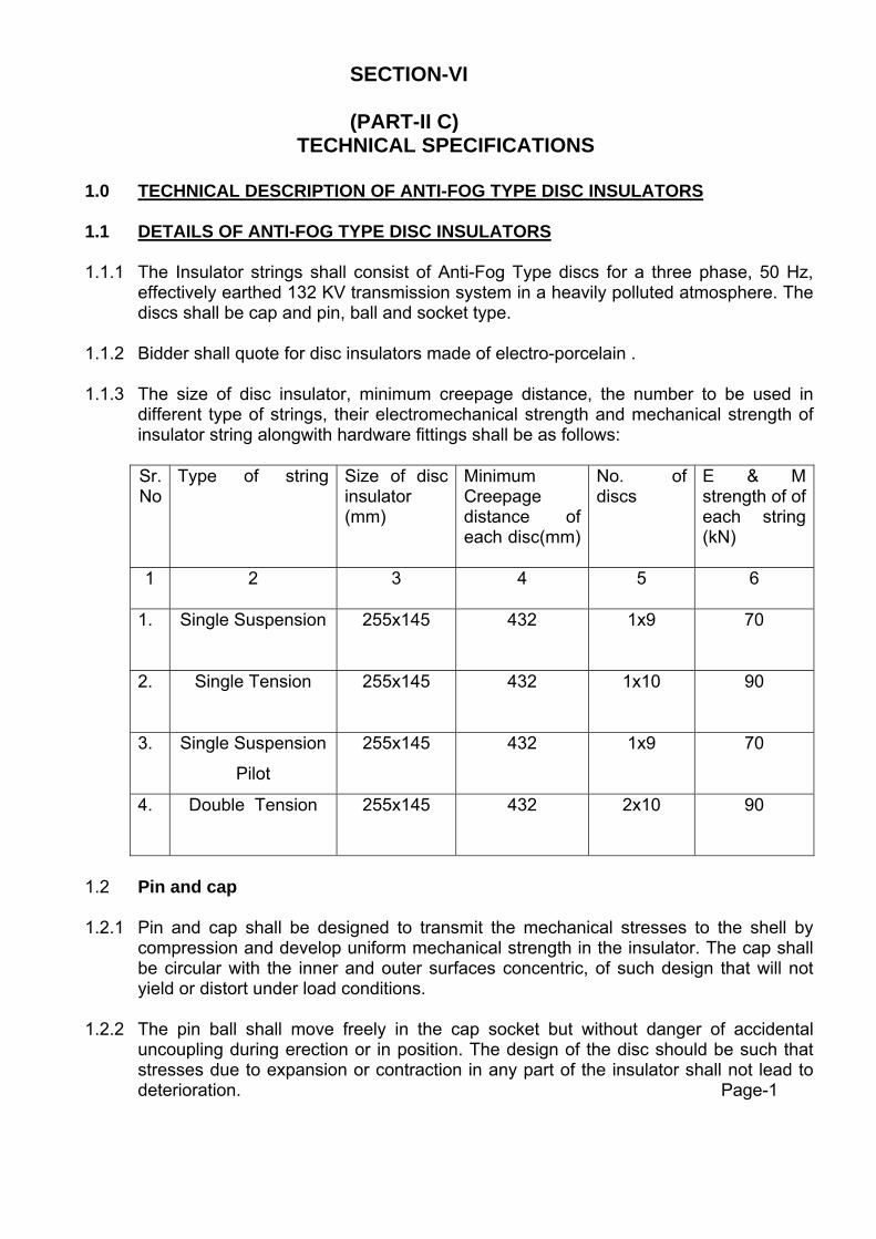
SECTION-VI
(PART-II C) TECHNICAL SPECIFICATIONS
1.0 TECHNICAL DESCRIPTION OF ANTI-FOG TYPE DISC INSULATORS 1.1 DETAILS OF ANTI-FOG TYPE DISC INSULATORS 1.1.1 The Insulator strings shall consist of Anti-Fog Type discs for a three phase, 50 Hz,
effectively earthed 132 KV transmission system in a heavily polluted atmosphere. The discs shall be cap and pin, ball and socket type.
1.1.2 Bidder shall quote for disc insulators made of electro-porcelain . 1.1.3 The size of disc insulator, minimum creepage distance, the number to be used in
different type of strings, their electromechanical strength and mechanical strength of insulator string alongwith hardware fittings shall be as follows: Sr. No
Type of string
Size of disc insulator (mm)
Minimum Creepage distance of each disc(mm)
No. of discs
E & M strength of of each string (kN)
1 2 3 4 5 6
1. Single Suspension 255x145 432 1x9 70
2. Single Tension 255x145 432 1x10
90
3. Single Suspension
Pilot
255x145 432 1x9 70
4. Double Tension 255x145 432 2x10
90
1.2 Pin and cap 1.2.1 Pin and cap shall be designed to transmit the mechanical stresses to the shell by
compression and develop uniform mechanical strength in the insulator. The cap shall be circular with the inner and outer surfaces concentric, of such design that will not yield or distort under load conditions.
1.2.2 The pin ball shall move freely in the cap socket but without danger of accidental
uncoupling during erection or in position. The design of the disc should be such that stresses due to expansion or contraction in any part of the insulator shall not lead to deterioration. Page-1

1.3 Security clip 1.3.1 Security clip for use with ball and socket coupling shall be of R-shaped hump type
which shall provide positive locking of the coupling as per IS: 2486- (part-III)/ IEC:372. The legs of the security clips shall be spread after installation to prevent complete withdrawal from the socket. The locking device should be resilient, corrosion resistant and of suitable mechanical strength. There shall be no rise of the locking device being displaced accidentally or being rotated when in position. Under no circumstances shall locking device allow separation of insulator units or fittings.
1.3.2 The hole for the security clip shall be countersunk and the clip shall be of such that the eye of clip may be engaged by a hot line clip puller to provide for disengagement under energized conditions. The force required to pull the security clip into its unlocked position shall not be less than 50 N (5 kg) or more than 500 N (50 kg).
1.4 Ball and socket Designation
The dimensions of the balls and sockets for 70 KN & 90 kN Anti-Fog Type discs shall be of 16mm Alt-‘B’ designation respectively in accordance with the standard dimensions stated in IS:2486- (Part-II)/IEC: 120.
1.5 Dimensional Tolerance of Insulator Disc.
Permitted dimensional tolerances of the Anti-Fog Type disc insulators shall be as under:- a) On all dimensions for which ± (0.04d + 1.5) mm where special tolerance do not apply d being the dimension in mm. b) On spacing of string insulator unit ± (0.03S + 0.3) mm where S is spacing in mm.
1.6 Interchangeability
The disc insulators inclusive of the ball and socket fittings shall be of standard design suitable for use with the hardware fittings of any make confirming to relevant Indian/International standards.
1.7 Corona and RI performance
All surfaces must be clean, smooth, without cuts, abrasions or projections. No part shall be subjected to excessive localised pressure. The metal parts and porcelain shall be so designed and manufactured that it shall not generate any Radio Interference beyond specified limit and not produce any noise generating corona under all operating conditions.
1.8 Maintenance 1.8.1 The disc insulators offered shall be suitable for employment of hot line maintenance
techniques so that the usual hot line operations can be carried our with ease, speed and safety.
1.8.2 Bidders shall indicate the methods generally used in the routine hot and dead line
maintenance of EHV line for which similar disc insulators have been supplied by them. Bidders shall also indicate the recommended periodicity of such maintenance. Page-2

1.9 Materials
1.9.1 Porcelain
The porcelain used in the manufacture of shells shall be sound, free from defects thoroughly vitrified and smoothly glazed.
1.9.2 Glaze
The finished porcelain shall be glazed in Brown colour. The glaze shall cover all exposed parts of the insulator and shell have a good luster, smooth surface and good performance under the extreme weather conditions of a tropical climate. It shall not be cracked or chipped by ageing under the normal service conditions. The glaze shall have the same co-efficient of expansion as that of the porcelain body throughout the working temperature range.
1.9.3 Cement
Cement used in the manufacture of the insulator shall not cause fracture by expansion or loosening by contraction. The cement shall not give rise to chemical reaction with metal fittings and its thickness shall be as small and uniform as possible. Proper care shall be taken to correctly centre and locate individual parts during cementing.
1.9.4 Pins and Caps Pins and caps shall be made of drop forged steel and malleable cast iron/ spherodal graphite iron / drop forged steel respectively, duly hot dip galvanized and shall not be made by jointing, welding, shrink fitting or any other process from more than one piece of material. 1.9.5 Security Clips Security clips shall be made of good quality stainless steel or phosphor bronge as per IS:1385-1968. 2.5% extra security clip shall be provided. 1.10 Workmanship 1.10.1 All the material shall be of the latest design and conform to the best modern
practices adopted in the extra High voltage field. Bidders shall offer only such insulators as are guaranteed by him to be satisfactory and suitable for 132 kV transmission line and will give continued good service.
1.10.2 The design, manufacturing process and material control at various stages shall
be such as to give maximum working load, highest mobility, best resistance to corrosion, good finish and elimination of sharp edges and corners to limit corona and radio interference.
1.10.3 The design of the insulators shall be such that stresses due to expansion and
contraction in any part of the insulator shall not lead to deterioration. 1.10.4 Metal caps shall be free from cracks, seams, shrinks, air holes, burrs and rough edges. All surfaces of the metal parts shall be perfectly smooth with no projecting points or irregularities which may cause corona. All load bearing surfaces shall be smooth and uniform so as to distribute the loading stresses uniformly.
Page-3

1.10.5 All ferrous parts shall be hot dip galvanized to give a minimum average coating of Zinc equivalent to 610 gm/sq m and shall be in accordance with the requirement of IS: 2629-1966 and shall satisfy the tests mentioned in IS: 2633-1972. The zinc used for galvanizing shall be of grade Zn 99.95 as per IS:209-1979. The zinc coating shall be uniform, adherent, smooth, reasonably bright, continous and free from imperfections such as flux, ash, rust stains, bulky white deposits, and blisters. The galvanized metal part shall be guaranteed to withstand atleast six successive dips each lasting for one (1) minute duration under the standard preece test. 1.10.6 Before ball fittings are galvanized, all die flashing on the shank and on the bearing surface of the ball shall be carefully removed without reducing the dimensions below the design requirements
1.10.7 The design of the insulators shall be such that the shell shall not engage directly with hard metal. The design shall also be such that when units are coupled together there is no contact between the shell of one unit and metal of the next adjacent unit. The design of the shell ribs shall be such that the security clip of the insulator can be engaged and disengaged easily with hot stick without damaging the shell ribs.
1.10.8 Insulator units after assembly shall be concentric and co-axial within limits as
permitted by the relevant Indian standards. 1.10.9 The manufacturer of the disc insulators shall guarantee an insulator failure rate
not exceeding 1 (one) per 10000 (ten thousand) per year. In case the annual failure rate during the first ten years of service exceeds the above figure, the manufacture shall supply to the HVPNL free of cost spare insulators equal to 10 time the excess failure.
1.10.10 The manufacture shall guarantee that there shall not be any decapping of
insulators on line under normal operating conditions. In event of any decapping and subsequent line drop, during the first three years of service the manufacturer shall have to pay Rs. 50,000/- (Rs. Fifty thousand only) per dropped string towards expenditure to be incurred by HVPNL for this repair.
1.11 Equipment Marking. 1.11.1 Each insulator disc shall be legibly and indelibly marked with the trademark of the
manufacture and year of manufacture. The guaranteed combined mechanical and electrical strength shall be indicated in kilo Newton’s followed by the word “kN” to facilitate easy identification and to ensure proper use.
1.11.2 For porcelain insulator, the marking shall be on porcelain. The marking shall be
printed, not impressed and shall be applied before firing.
1.11.3 One 10 mm thick ring of suitable quality of paint shall be marked on the cap of each insulator of particular strength for easy identification of the type of insulator. The paint shall not have any deteriorating effect on the insulator performance. Following codes shall be used as identification mark.
For 70 KN disc : red For 90KN disc : Black
Page-4

1.12 Bid Drawings
1.12.1 The successful Bidder shall submit 4 sets of following fully dimensional drawings complete in all respect for approval to HVPNL as per time schedule given in Bar Chart:-
a) Shell diameter and ball to ball spacing with manufacturing tolerances.
b) Minimum creepage distance with positive tolerance. c) Protected creepage distance. d) Eccentricity of the disc
i) Axial run out
ii) Radial run out
e) Unit mechanical an electrical characteristics.
f) Size and weight of ball an socket parts
g) Weight of unit insulator disc.
h) Materials
i) Identification mark
j) Manufacturer’s catalogue number
1.12.2 After placement of award, the manufacturer shall submit full dimensioned
insulator drawings containing all the details as given in clause No. 1.12.1 above, in four (4) copies to HVPNL representative for approval. After getting approval from HVPNL representative and successful completion of all the type tests, the manufacturer shall submit. 12 more copies of the same drawing to the HVPNL representative for further distribution and field use at HVPNL representative ’s end.
1.12.3 After placement of award the manufacture shall also submit fully
dimensioned insulator create drawing for different type of insulators.
Page-5

2. Tests and standards
2.1 TESTS The following acceptance, routine tests and tests during manufacture shall be carried on the disc insulator individually and alongiwth hardware fittings. For the purpose of this clause: -
2.1.1 Acceptance tests shall mean those tests which are to be carried out on
samples taken from each lot offered for pre-despatch inspection for the purpose of acceptance of that lot.
2.1.2 Routine tests shall mean those tests, which are to be carried out on each
disc insulator/hardware fitting to check requirements which are likely to vary during production.
2.1.3 Tests during manufacture shall mean those tests which are to be carried out
during the process of manufacture and end inspection by the manufacture to ensure the desired quality of the end product to be supplied by him.
2.1.4 For all acceptance tests, the acceptance values shall be the values
guaranteed by the bidder in the Guaranteed Technical Particulars of his proposal or the acceptance value specified in this specification whichever is more stringent for that particular test.
2.2. Type tests
The equipment should be offered type tested. Test reports should not be more than seven years old reckoned from the date of bid opening in respect of all the tests carried out in accredited laboratories ( based on ISO/IEC) by a reputed accreditatic body or witnessed by HVPNL or another electric power utility and be submitted by the successful Bidder to HVPNL for approval as per schedule given in Bar chart.
2.3 Acceptance tests
2.3.1 For Disc Insulators
b) Visual examination IS:731-1971 b) Verification of dimensions IS:731-1971 c) Temperature cycle test IS:731-1971
d) Galvanizing test IS:731-1971 e) Electromechanical failing load test IS:731-1971
f) Mechanical Performance test IEC:60383-1993
g) Residual strength test IEC:60383-1993
Page-6

h) Eccentricity test IEC:60383-1993
i) Test on locking device for ball IS: 2486 (Part-IV)
and socket coupling j) Vibration test
(only once for each type of disc Annexure-A Insulator under the contract)
2.4 For porcelain insulators
a) Puncture test IEC: 60383-1993/IS:731- 1971 b) Porosity test IS:731-1971
2.5 Routine Tests
2.5.1 For Disc Insulators
a) Visual Inspection ) ) IS: 731-1971 b) Mechanical routine test ) Clause 10.13, 10.14 & 10.15 c) Electrical routine test )
2.5.2 Tests During Manufacture
On all components as applicable a) Chemical analysis of zinc used )
for Glavansing ) )
b) Chemical analysis, mechanical ) metallographic test and magnetic ) Annexure-A
particle inspection for malleable ) castings. )
c) Chemical analysis, hardness ) tests and magnetic particle ) Annexure-A inspection for forgings ) ) d) Hydraulic internal pressure ) tests on disc insulator shells ) ) e) Metallurgical tests for metal )
Fittings only (in black condition) ) i) Grain size ) ii) Inclusion rating ) iii) Micro structure )
Page - 7
2.6 Testing Expenses
The entire cost of testing for acceptance and routine tests and tests during manufacture specified herein shall be treated included in the quoted Ex-works price except for the expenses of the inspector/HVPNL representative.
2.7 Schedule of testing and additional tests
2.7.1 The bidder has to indicate the schedule of following activities in their bids:
a. Submission of drawing for approval.
b. Submission of Quality Assurance programme for approval.
2.7.2 The HVPNL representative reserves the right of having at his own expense any other test (s) of reasonable nature carried out at manufacturer’s premises, at site, or in any other place in addition to the aforesaid type, acceptance and routine tests to satisfy himself that the material comply with the specifications.
2.7.3 The HVPNL representative also reserves the right to conduct all the tests
mentioned in this specification at his own expense on the samples drawn from the site at manufacturer’s premises or at any other test center. In case of evidence of non compliance, it shall be binding on the part of the manufacture to prove the compliance of the items to the technical specifications by repeat tests or correction of deficiencies, or replacement of defective items, all without any extra cost to the HVPNL representative .
2.8 Co- ordination for testing
The Bidder/insulator manufacturer shall have to co-ordinate testing of insulators with hardware fittings to be supplied by other manufacturer and shall have to also guarantee overall satisfactory performance of the insulators with the hardware fittings.
2.9 Test Reports
2.9.1 Record of routine test reports shall be maintained by the manufacturer at his works for periodic inspection by the HVPNL representative ’s representative.
2.9.2 Test certificates of test during manufacture shall be maintained by the
manufacturer. These shall be produced for verification as and when desired by the HVPNL representative .
2.10 INSPECTION
2.10.1 The HVPNL representative ’s representative shall at all times be entitled to have access to the works and all places of manufacture, where insulators, and its component parts shall be manufactured and the representatives shall have full facilities for unrestricted inspection of the manufacturer’s and sub-manufacturer’s works, raw materials, manufacture of the material and for conducting necessary test as detailed herein.
2.10.2 The material for final inspection shall be offered by the manufacturer only under
packed condition as detailed in clause No. 2.12 of the specification. The HVPNL representative shall select samples at random from the packed lot for carrying out acceptance tests.
Page-8

2.10.3 The manufacturer shall keep HVPNL informed in advance of the time of starting and the progress of manufacture of material in their various stages so that arrangements could be made inspection.
2.10.4 No material shall be despatched from its point of manufacture before it has been
satisfactorily inspected and tested unless the inspection is waived off by the HVPNL representative in writing. In the latter case also the material shall be despatched only after satisfactory testing for all tests specified herein have been completed.
2.10.5 The acceptance of any quantity of material shall be in no way relieve the
manufacturer of his responsibility for meeting all the requirements of the specification and shall not prevent subsequent rejection, if such material are later found to be defective.
2.11 Packing and Marking
2.11.1 All insulators shall be packed in strong seasoned wooden crates. The gross weight of the crates along with the material shall not normally exceed 200 kg. to avoid handling problem. For marine transportation crates shall be palleted.
2.11.2 The packing shall be of sufficient strength of withstand rough handling during transit,
storage at site and subsequent handling in the field. 2.11.3 Suitable cushioning, protective padding, or dunnage or spacers shall be provided to
prevent damage or deformation during transit and handling.
2.11.4 All packing cases shall be marked legibly and correctly so as to ensure safe arrival at their destination and to avoid the possibility of goods being lost or wrongly despatched on account of faulty packing and faulty or illegible markings. Each wooden case/crate shall have all the markings stenciled on it in indeliable ink.
2.12 Standards 2.12.1 The insulators strings and its components shall conform to the following
Indian/international standards which shall mean latest revision, with amendments/changes adopted and published, unless specifically stated otherwise in the Specification.
2.12.2 In the event of supply of insulators conforming to standards other than specified the
Bidder shall confirm in his bid that these standards are equivalent to those specified. In case of award salient features of comparison between the standards proposed by the manufacturer and those specified in his document will be provided by the manufacturer to establish equivalence.
Sr. No. Indian Standard Title International
Standards
1. IS: 209-1992 Specification for Zinc BS: 3436-1986
2 IS: 406-1991 Method of chemical analysis of slab zinc
3 IS: 731-1991 Porcelain insulators for overhead power line with a nominal voltage greater than 1000V
BS: 137-1982 (I&II) IEC:383-1993
Page-9

4 IS:2071
Part (I)-1993 Part (II)-1991 Part (III)-1991
Methods of High Voltage Testing
IEC:60-1-1989
5 IS:2486
Specification for Insulator fittings for overhead power line with a nominal voltage greater than 1000V
Part (I)-1993 General Requirements and tests
BS:3288-1979
Part (II)-1989 Dimensional Requirements IEC:120-1984 Part (III)-1991 Locking devices IEC:372-1984 6 IS:2629-1990 Recommended practice for
hot Dip galvanization for iron and steel
ISO:1461 (E)
7 IS:2633-1992 Testing of Uniformity of coating of zinc coated articles
8 IS:3188-1988 Dimensions for Disc Insulators
IEC:305-1978
9 IS:6745- 1990 Determination of weight of zinc coating on zinc coated iron and steel articles.
ISO:1460 (E)
10 IS:8263-1990 Methods of RI test on HV insulators
IEC:437-1973 NEMA Publication No. 107/1964/CISPR
11 IS:8269-1990 Methods for switching impulse test on HV insulators
IEC:506-1975
12 Thermal mechanical performance test and mechanical performance test on string insulator units.
IEC:575-1977
13 Salt fog pollution voltage withstand test
IEC:507-1991
14 Residual strength of string insulator units of glass or ceramic material for overhead line after mechanical damage of the dielectric
IEC:797-1984
15 Guide for the selection of insulators in respect of polluted conditions
IEC:815-1986
16 Tests on insulators of ceramic material or glass for overhead line with a nominal voltage greater than 1000V
IEC:383-1993
Page-10

…………………………………………………………………………………… The standard mentioned above are available from:
…………………………………………………………………………………………………… Reference Abbreviation Name and Address …………………………………………………………………………………………………… BS British Standards, British Standards Institution 101, Pentonvile Road, N-19-ND UK IEC/CISPR International Electrotechnical Commission, Bureau Central De la Commission, Electro Technique International, 1 Rue de verembe, Geneva Switzerland IS Bureau of Indian Standards, Mank Bhavan,-9, Bahadur Shah Zafar Marg, New Delhi 110001, INDIA ISO International Organisation for Standardization, Danish Board Of Standardization Danish
Standardising Sraat, Aurehoegvej- 12 DK-2900, Heeleprup, DENMARK.
NEMA National Electric Manufacture
Association, 155, East 44th Street,
New York, NY 10017 U.S.A.
Page-11
ANNEXURE-A 1. Tests on complete strings with Hardware fittings. 1.1 Voltage distribution test The voltage across each insulator unit shall be measured by sphere gap
method. The result obtained shall be converted into percentage. The voltage across any disc shall not exceed 20% for suspension insulator string and 22% for tension insulator string.
1.2 Mechanical strength test
The complete insulator string along with its hardware fitting excluding arcing horn, and suspension assembly/dead end assembly shall be subjected to a load equal to 50% of the specified minimum ultimate tensile strength (UTS) which shall be increased at a steady rate to 67% of the minimum UTS specified. The load shall be held for five minutes and then removed. After removal of the load, the string components shall not show any visual deformation and it shall be possible to disassemble them by hand. Hand tools may be used to remove cotter pins and loosen the nuts initially. The string shall then be reassembled and loaded to 50% of UTS and the load shall be further increased at a steady rate till the specified minimum UTS and held for one minute. No fracture should occur during this period. The applied load shall then be increased until the failing load is reached and the value recorded.
1.3 Vibration test
The suspension string shall be tested in suspension mode, and tension string in tension mode itself in laboratory span of minimum 30 metres. In the case of suspension string a load equal to 600 Kg shall be applied along the axis of the suspension string by means of turn buckle. The insulator string along with hardware fittings and conductor tensioned at 2500 Kgf shall be secured with clamps. The system shall be suitable to maintain constant tension on the conductor throughout the duration of the test. Vibration dampers shall not be used on the test span. The conductor shall be vertically vibrated at one of the resonance frequencies of the insulators string (more than 10 Hz) by means of vibration inducing equipment. The peak to peak, displacement in mm of vibration at the antinode point nearest to the string shall be measured and the same shall not be less than 1000 / f1.8 where is the frequency of vibration in cycles/sec. The insulator string shall be vibrated for not less than 10 million cycles without any failure. After the test the disc insulators shall be examined for looseness of pins and cap or any crack in the cement. The hardware shall be examined for looseness, fatigue failure and mechanical strength test. There shall be no deterioration of properties of hardware components and insulators after the vibration test. The insulators shall be subjected to the following tests as per relevant standards:
Page-12

TESTS PERCENTAGE OF DISC INSULATOR UNITS TO BE TESTED
a) Temperature cycle test 60
Followed by mechanical Performance test
b) Puncture test 40
2. On disc insulator units 2.1 Steep wave front test
The following test shall be performed on 10 nos. of disc insulators selected at random from the lot offered for selection of sample for type test. a) Each insulator unit shall be subjected to five successive positive and
negative impulse flashovers with a wave having minimum effective rate of rise of 2500 kV per microseconds.
b) Each unit shall be subjected to three dry power frequency voltage
flashovers.
Acceptance Criteria An insulator shall be deemed to have met the requirement of this test if, having been successfully subjected to the ten impulse flashovers, the arithmetic mean of the three subsequent dry power frequency voltage flashover values equals or exceeds 95% of the rated dry power frequency flashover voltage. An insulator shall be deemed to have failed to meet the requirement of above testing , if a) It has not flashed over when the oscillogram or peak voltage indicator
shows a marked reduction in voltage.
or
b) Any one of the subsequent three dry power frequency voltage flashover value is less than 80% of the value specified. Failure of any one unit either in the steep front of wave or subsequent low frequency voltage test shall be cause for testing on double number of units.
Page-13

2.2 Hydraulic Internal Pressure Test on Shells
The test shall be carried out on 100% shells before assembly. The details regarding test will be as discussed and mutually agreed to by the manufacturer and HVPNL in Quality Assurance Programme.
2.4 Thermal Mechanical Performance Test
Thermal Mechanical Performance Test shall be performed in accordance with IEC-383-1-1993 clause 20 with the following modifications:
(1) The applied mechanical load during this test shall be 70% of the
rated electromechanical strength value. (2) The acceptance criteria shall be
a) X greater than or equal to R+3S. Where X Mean value of the individual mechanical failing load. R Rated electromechanical strength test.
S Standard deviation
b) The minimum sample size shall be taken as 20.
c) The individual electromechanical failing load shall be at least equal to the rated value. Also puncture shall not occur before the ultimate fracture.
2.5 Electromechanical Failing Load Test
This test shall be performed in accordance with clause 18 and 19 of IEC-383 with the following acceptance.
i) X gareater than or equal to R+3S
Where X Mean value of the Electromechanical strength test. R Rated electromechanical strength test. S Standard deviation
ii) The minimum sample size shall be taken as 20. However for larger lot size IEC 591 shall be applicable.
iii) The individual electro-mechanical strength shall be at least equal to the
rated value. Also electrical puncture shall not occur before the ultimate fracture.
Page-14
2.6 Residual strength test
The above test shall be performed as per clause 4.4 and 4.5 of IEC 797 preceded by the temperature cycle test, on orcelain disc insulators. The sample size shall be 25 and the evaluation of the results and acceptance criteria shall be as per clause No 4.6 of IEC 797.
3. Tests on all components (As applicable) 3.1 Chemical Analysis of Zinc used for Galvanizing
Samples taken form the zinc ingot shall be chemically analysed as per IS: 209-1979. The purity of zinc shall not be less than 99.95%.
3.2 Tests for Forgings
The chemical analysis, hardness tests and magnetic particle inspection for forgings, will be as per the internationally recognized procedures for these tests. The sampling will be based on heat number and heat treatment batch the details regarding test will be as discussed and mutually agreed to by the manufacturer and HVPNL in quality assurance Programme.
3.3 Tests on castings
The chemical analysis, mechanical and metallographic tests and magnetic particle inspection for castings will be as per the internationally recognized procedures for these tests. The samplings will be based on heat umber and heat treatment batch. The details regarding test will be as discussed and mutually agreed to by the manufacturer and HVPNL in quality assurance programme.
Page-15

TECHNICAL SPECIFICATION FOR 145 kV BUS POST INSULATORS 1. SCOPE
This specification covers design, Engineering, manufacture, stage testing, inspection and testing before despatch packing, forwarding and delivery at site of 145 kV outdoor type bus Post Insulators and its clamps at the Gantries. It is not the intent to specify completely all the details of design and construction of the insulator. However, the insulator shall conform in all respects to the high standard of engineering design and workmanship and shall be capable of performing in continuous commercial operation up to the Bidder’s guarantee in a manner acceptable to the HVPNL. The equipment offered shall be complete in all components necessary for its effective and trouble free operation. Such components shall be deemed to be within the scope of supply irrespective of whether those are specially brought out in this specification or not. All similar parts particularly movable ones shall be interchangeable.
2. STANDARD
The Post Insulators and their Hardwares shall comply as regards general requirements, test voltages and test with the latest edition of IS 2544/1973 IS-5350 (P-II) 1973 IS-5350 (P-III) 1971/IEC-168/1979 except in so far as the same may be modified by this Specification.
3. TYPE AND RATING The 145 kV Bus Post Insulators are required for outdoor-system conforming to IS 2544/1973 or latest version thereof suitable for heavily polluted atmosphere. The Post Insulators shall be specifically suitable to meet the particular requirements of ultimate torsional strength and cantilever loads etc. which they will be called upon to resist during service at the rated voltage. The principal rating of bus Post Insulators shall be as under: -
Sr. No.
Particulars Unit
i. Nominal system voltage
kV 132
ii. Highest system voltage
kV 145
iii. Rated frequency 50+/-2.5H iv. Minimum creepage
distance mm 3625
v. One minute power frequencywithstand voltage
kV(rms) 275
vi. Impulsewithstand voltage (+ve & -ve)
kV(peak) 550
vii. Minimum visual discharge voltage level (extinction)
kV(rms) -
Page-16

viii. Radio interference voltage (Micro volt at 1 MHz) at a system voltage of 156 kV.
Micro Volt >500
ix. Cantilever strength (Upright)
Kg. 400
x. Torsion strength nm 3000 xi. Bending strength N 4000 xii. Tensile strength N 50000 xiii. Compressive strength N 100000 xiv. Applicable standard xv. Pitch Circle Dia: a. Top mm 127 b. Bottom mm 178 xvi. Height of insulator mm 1220+1 xvii. No. of Insulator per
stack No. 1
4. CLIMATIC CONDITION
As per 1.6 of Section-VI, Part-1.
5. GENERAL REQUIREMENT
145 kV Bus Post Insulator shall be either solid core or polycon type insulators complete with all fittings and accessories required for holding single ACSR Panther as the case of line may be . The bus Post Insulator pedestal shall be suitable for fixing on the Gantries. The bus Post Insulator shall be provided with a completely galvanised steel base designed for mounting on the Gantries. The base and mounting arrangement shall be such that the insulator shall be rigid and self supporting and no guying or cross bracings between phases shall be necessary. Cap to be provided on top of the insulator shall be of high grade cast iron or malleable steel casting. It shall be machine faced and hot dip galvanised. The cap shall have four nos. of tapped holes spaced on a pitch circle diameter to accommodate the terminal clamp . The holes shall be suitable for bolts with threads having anticorrosive protection. The effective depth of threads shall not be less than the nominal diameter of the bolt. The Post Insulator clamps are to be fitted on the top of the bus Post Insulator for holding single conductor ACSR Panther tightly and rigidly. The clamps shall be made of Aluminium alloy and shall comply with relevant ISS. The clamps shall be supplied with galvanised steel studs of the suitable size and maintain the requisite pressure to ensure good and tight joint of low resistance. The insulators shall be entirely free from sharp edges, ridges or points and shall not exhibit appreciable corona formation during service. Castings shall be free from blow holes, flaws, cracks and other defects and shall be smooth, close grained and of true forms and dimensions.
Page-17
The porcelain shall be white, finished brown glazed, non-porous of high di-electric, mechanical and thermal strength, free from defects and thoroughly vitrified. Cement used shall be of high quality, durable and high strength Portland cement. Cement is not to be treated as an adhesive medium between the porcelain and metal parts of an insulator. Preference will be given to a fixing medium of an approved metal alloy. Cement shall be a replenishment material for filling gap between the porcelain and metal parts to fix them.
6. GALVANISING
All the ferrous metal parts shall be hot dip galvanised smoothly, as per IS 3638 (as amended up to date). IS 2633 or any other equivalent authoritative standard. The material shall be galvanised only after shop operations upon it have been completed. The metal parts before galvanising should be thoroughly cleaned of any paint, grease, rust, scales or alkalis, or any foreign deposit which are likely to come in the way of galvanising process. The metal parts coating shall withstand minimum four for one minute dips in copper sulphate solution as per IEC-168. The bus Post Insulator unit shall be assembled in a suitable jig to ensure correct positioning of the top and bottom metal fittings relative to one another. The faces of the metal fittings shall be parallel and at right angles to the axis of the insulator and the corresponding holes in the top and the bottom metal fittings shall be in a vertical plane containing the axis of the insulator. All nuts, bolts and spring washers etc. required for the assembly of the complete insulator stack shall be in scope of supply. The bolts and nuts shall be hot dip galvanised and shall be of high strength generally conforming to IS-136 or any other equivalent international standard.
7. TESTS 7.1 Type Tests The equipment should be offered type test. Test reports should not be more than
seven years old reckoned from the date of bid opening in respect of all the tests
carried out in accredited laboratories ( based on ISO/IEC) by a reputed accreditatic
body or witnessed by HVPNL or another electric power utility and be submitted by
the successful bidder to HVPNL for approval as per schedule given in Bar chart.
1. Visual examination 2. Verification of dimensions 3. Visible discharge test 4. Impulse voltage withstand test 5. Dry power frequency voltage withstand test. 6. Wet power frequency voltage withstand test. 7. Temperature cycle test 8. Test for mechanial strength 9. Puncture test 10. Porosity test 11. Galvanising test
Page-18

7.2 Acceptance and Routine Tests
7.2.1 All the acceptance and routine tests as detailed below shall be carried out by the supplier in the presence of HVPNL representative. No material shall be dispatched without the approval of test certificates:-
1. Verification of dimensions 2. Temperature cycle test 3. Test for mechanial strength 4 Puncture test 5. Porosity test
6. Galvanising test 8. INSPECTION
The inspection may be carried by the HVPNL at any stage of manufacture. The successful Bidder shall grant free access to the HVPNL representative at a reasonable time when the work is in progress. Inspection and acceptance of any equipment under this Specification by the HVPNL shall not relieve the supplier of his obligation of furnishing equipment in accordance with the Specification and shall not prevent subsequent rejection if the equipment is found to be defective. The Bidder shall keep the HVPNL informed in advance about the manufacturing programme so that arrangement can be made for inspection. The HVPNL reserves the right to insist for witnessing the acceptance/routine testing of the bought out items.
9. GUARANTEED DATA
Guaranteed technical particulars and other technical data in respect of equipment/material offered should be furnished duly signed in the performa given in GTPs. Any other particulars considered necessary may also be given in addition to those listed in the schedule.
10. DRAWING AND LITERATURE
The successful bidder shall submit 4 sets of following fully dimensional drawings complete in all respect for approval to HVPNL as per time schedule given in Bar Chart.
11. MARKING
Each porcelain insulator unit shall legibly and indelibly be marked to show the following: a) Name or Trade Mark of the manufacture. b) Month and year of manufacture. c) Country of manufacture. Marking on the porcelain shall be printed and shall be applied before firing.
Page-19

12. PACKING AND FORWARDING 12.1 The equipments shall be packed in crates suitable to withstand handling during
transport and outdoor storage during transit. The supplier shall be responsible for any damage to the equipment during transit, due to improper and inadequate packing. The easily damageable material shall be carefully packed and marked with the appropriate caution symbols. Wherever necessary, proper arrangement for lifting, such as lifting hooks etc. shall be provided. Any material found short inside the packing cases shall be supplied by supplier without any extra cost.
12.2 Each consignment shall be accompanied by a detailed packing list containing the
following information: -
a) Name of the consignee. b) Details of the consignment. c) Destination. d) Total weight of consignment. e) Sign showing upper/lower side of the crate. f) Handling and unpacking instructions. g) Bill of material indicating contents of each package.
Page-20

SECTION-VI (PART-II D) TECHNICAL SPECIFICATION (PACKAGE-A) CONTENTS
S. No Clause Page No.
1. Hardware Fittings for lines with ACSR Panther 1 2. Accessories for lines with ACSR Panther 11 3. Earthwire Accessories of size 7/3.15mm 17 4 Tests and Standards 40 8. Type Tests 40 9 Annexure-A 51 10 Annexure-B 59

SECTION-VI (PART-II D) TECHNICAL SPECIFICATIONS 1. Technical Description of Hardware Fittings 1.1 DETAILS OF HARDWARE FITTINGS FOR LINES WITH ACSR PANTHER
CONDUCTOR 1.1.1 The hardware fittings shall be as per the specification drawings enclosed with this part
of the specification. Each hardware fitting shall be supplied complete in all respects and shall include the following hardware parts.
1.1.2 Single suspension, Single Tension, Single suspension (Pilot), Double Suspension and
Double Tension hardware fittings, shall be supplied suitable for attaching to hanger/strain plate fixed to tower. The dimension of hanger/strain plate and hole etc. will be intimated to the successful bidder.
1.1.3 Suitable arcing horn/intermediate arcing horns as specified in clause 1.8 hereinafter.
1.1.4 Suitable yoke plates complying with the specifications given hereunder.
1.1.5 Suspension and dead end assembly to suit conductor size as detailed in clause 1.10
and 1.11 hereinafter.
1.1.6 Other necessary fittings as eye links, ball clevis, socket clevis, clevis eye, U-clevis and chain link etc. to make the hardware fittings complete.
1.1.7 2.5% extra fasteners and Aluminum filler plugs.
1.2 Dimensions of Insulator String Alongwith Hardware Fitting
The various limiting dimensions of the various Suspension, pilot and tension insulator strings alongwith hardware fittings shall be as per the specification drawings enclosed with this part of the specification.
1.3 Interchangeability 1.3.1 The hardware for insulator strings with disc insulators together with ball and socket
fittings shall be of standard design, so that these hardware are interchangeable with each other and suitable for use with disc insulators of any make conforming to relevant Indian/International Standard.
1.4 Corona and RI Performance
Sharp edges and scratches on all the hardware fittings shall be avoided. All surfaces must be clean, smooth, without cuts and abrasions or projections. The Bidder must give suitable assurance about the satisfactory corona and radio interference performance of the materials offered by him
1.5 Maintenance
1.5.1 The hardware fittings offered shall be suitable for employment of hot line maintenance techniques so that usual hot line operations cab be carried out with ease, speed and safety. The technique adopted for hot line maintenance shall be generally bare hand method & hot stick method. The Bidder should clearly establish in the bid, the suitability of his fittings for hot line maintenance.
Page-1
1.6 Designation 1.6.1 Ball and Socket Designation
The dimensions of the ball and socket shall be of 16mm Alt-‘B’ for 70 KN and 90 Disc Insulators. The designation should be in accordance with the standard dimensions stated in IS 2486 (Part-II)/ IEC: 120. The dimensions shall be checked by the appropriate gauge after galvanising only.
1.7 Security Clips and Split Pins 1.7.1 Security clips for use with ball and socket coupling shall be R-shaped, hump
type which provides positive locking of the coupling as per IS:2486 (Part-III) /IEC : 372. The legs of the security clips shall be spread after assembly in the works to prevent complete withdrawal from the socket. The locking device should be resilient, corrosion resistant and of suitable mechanical strength. There shall be no risk of the locking device being displaced accidentally or being rotated when in position. Under no circumstances shall the locking devices allow separation of fittings.
1.7.2 The hole for the security clips shall be countersunk and the clip should be of
such design that the eye of clips may be engaged by a hot line clip puller to provide for disengagement under energised conditions. The force required to pull the security clip into its unlocked position shall not be less than 50 N (5 kg) or more than 500 N (50 kg).
1.7.3 Split pins shall be used with bolts & nuts. 1.8 Arcing Horn/Intermediate Arcing Horn 1.8.1 The arcing horn shall be either ball ended rod type or tubular type. 1.8.2 For insulators strings with disc insulators, the arcing horn shall be provided as
shown on the drawings of the hardware fittings in this specification. 1.8.3 The spark gap shall be so adjusted to ensure effective operation under actual
field conditions. 1.9 Yoke Plates
The strength of yoke plates shall be adequate to withstand the minimum ultimate tensile strength, as specified in the bid drawings.
The plates shall be either triangular or rectangular in shape as may be necessary. The design of yoke plate shall take into account the most unfavourable loading conditions likely to be experienced as a result of dimensional tolerances for disc insulators as well as components of hardware fittings within the specified range. The plates shall have suitable holes for fixing arcing horn. All the corners and edges should be rounded off with a radius of at least 3 mm. Design calculations i.e. for bearing & tensile strength, for deciding the dimensions of yoke plate shall be furnished by the bidder. The holes provided for bolts in the yoke plate should satisfy shear edge condition as per Clause No. 8.10 of IS: 800-1984.
Page-2

1.10 Suspension Assembly 1.10.1 The suspension assembly shall be suitable for ACSR Panther Conductor. 1.10.2 The suspension assembly shall include either free centre type suspension
clamp alongwith standard preformed armour rods or armour grip suspension clamp except for pilot insulator string for which only suitable envelope type suspension clamps shall be used.
1.10.3 The suspension clamp alongwith standard preformed armour rods set shall be
designed to have maximum mobility in any direction and minimum moment of inertia so as to have minimum stress on the conductor in the case of oscillation of the same.
1.10.4 The suspension clamp alongwith standard preformed armour rods/armour grip
suspension clamp set shall have a slip strength between 11 to 16 KN for ACSR Panther.
1.10.5 The suspension assembly shall be designed, manufactured and finished to give
it a suitable shape, so as to avoid any possibility of hammering between suspension assembly and conductor due to vibration. The suspension assembly shall be smooth without any cuts, grooves, abrasions, projections, ridges or excrescence which might damage the conductor.
1.10.6 The suspension assembly/clamp shall be designed so that it shall minimise the
static & dynamic stress developed in the conductor under various loading conditions as well as during wind induced conductor vibrations. It shall also withstand power arcs & have required level of corona/RIV performance.
1.10.7 FREE CENTER TYPE SUSPENSION CLAMP
For the free Center Suspension Clamp seat shall be smoothly rounded and curved into a bell mouth at the ends. The lip edges shall have rounded bead. There shall be at least two U-bolts for tightening of clamp body and keeper pieces together.
1.10.8 STANDARD PREFORMED ARMOUR ROD SET 1.10.8.1 The preformed Armour Rod Set suitable for ACSR Panther conductor shall be
used to minimise the stress developed in the conductor due to different static and dynamic loads because of vibration due to wind, slipping of conductor from the suspension clamp as a result of unbalanced conductor tension in adjacent spans and broken wire condition. It shall also withstand power arcs, chafing and abrasion from suspension clamp and localised heating effect due to magnetic power losses from suspension clamps as well as resistance losses of the conductor.
1.10.8.2 The preformed Armour rods set shall have right hand lay and the inside
diameter of the helics shall be less than the outside diameter of the conductor to have gentle but permanent grip on the conductor. The surface of the Armour rod when fitted on the conductor shall be smooth and free from projections, cuts and abrasions etc.
Page-3

1.10.8.3 The pitch length of the rods shall be determined by the Bidder but shall be less
than that of the outer layer of conductor and the same shall be accurately controlled to maintain uniformity and consistently reproducible characteristic wholly independent of the skill of linemen.
1.10.8.4 The length of each rod and diameter shall be as follows:
Length dia ACSR Panther 1930 ± 16 6.35 ± .10 The tolerance in length of the rods in complete set should be within 13 mm
between the longest and shortest rod. The ends of Armour rod shall be parrot billed.
1.10.8.5 The number of Armour rods in each set shall be Eleven. Each rod shall be
marked in the middle with paint for easy application on the line. 1.10.8.6 The amour rod shall not loose their resilience even after five applications.
1.10.8.7 The conductivity of each rod of the set shall not be less than 40% of the
conductivity of the International Annealed Copper Standard (IACS). 1.10.9 ARMOUR GRIP SUSPENSION CLAMP 1.10.9.1 The Armour grip suspension clamp shall comprise of retaining strap, support
housing, elastomer inserts with aluminum re-enforcement’s and AGS preformed rod set.
1.10.9.2 Elastomer insert shall be resistant to the effects of temperature up to 750 C,
Ozone ultraviolet radiations and other atmospheric contaminants likely to be encountered in service. The physical properties of the elastomer shall be of approved standard. It shall be electrically shielded by a cage of AGS preformed rod set. The elastomer insert shall be so designed that the curvature of the AGS rod shall follow the contour of the neoprene insert.
1.10.9.3 The AGS preformed rod set shall be as detailed in clause 1.10.8.1 to 1.10.8.7 in
general except for the following.
1.10.9.4 The length of the AGS preformed rods shall be such that it shall ensure sufficient slipping strength as detailed under clause 1.10.4 and shall not introduce unfavorable stress on the conductor under all operating conditions.
1.10.10 ENVELOPE TYPE SUSPENSION CLAMP
The seat of the envelope type suspension clamp shall be smoothy rounded and suitably curved at the ends. The lip edges shall have a rounded bend. There shall be at least two U-Bolts for tightening of clamp body and keeper pieces together. Hexagonal bolts and nuts with split pins shall be used for attachment of the clamp.
Page-4

1.11 DEAD END ASSEMBLY
1.11.1 The dead end assembly shall be suitable for ACSR Panther conductor. 1.11.2 The dead end assembly shall be compression type with provision for
compressing jumper terminal at one end. The angle of jumper terminal to be mounted should be 300 with respect to the vertical line. The area of bearing surface on all the connections shall be sufficient to ensure positive electrical and mechanical contract and avoid local heating due to I2 R losses. The resistance of the clamp when compressed on Conductor shall not be more than 75% of the resistance of equivalent length of Conductor.
1.11.3 Die compression areas shall be clearly marked on each dead-end assembly
designed for continuous die compressions and shall bear the words ‘COMPRESS FIRST’ suitably, inscribed near the point on each assembly where the compression begins. If the dead end assembly is designed for intermittent die compressions, it shall bear identification marks ‘COMPRESSION ZONE’ AND ‘NON-COMPRESSION ZONE’ distinctly with arrow marks showing the direction of compressions and knurling marks showing the end of the zones. Tapered aluminum filler plugs shall also be provided at the line of demarcation between compression & non-compression zone. The letters, number and other marking on the finished clamp shall be distinct and legible. The dimensional tolerances of the cross section of aluminum for dead end assembly for ACSR Panther conductor shall be as per the table given below: -
TABLE-I
Sl. No.
Item Dimension before Compression
Dimension after Compression
Outer dia
(mm)
Corner to corner width (mm)
Face to face width (mm)
Dead end Assembly 1. Aluminum sleeve 38±1 37±0.5 32±0.5 2. Steel 18±0.5 15.1±0.5 17.4±0.5
1.11.4 The assembly shall not permit slipping of, damage to, or failure of the complete
conductor or any part there of at a load less than 95% of ultimate tensile strength of the conductor.
Page-5

1.12 FASTENERS: BOLTS, NUTS AND WASHERS
1.12.1 All bolts and nuts shall conform to IS: 6639-1972/ISO-R-272-1968. All bolts and nuts shall be galvanized. All bolts and nuts shall have hexagonal heads, the heads being forged out of solid truly concentric, and square with the shank, which must be perfectly straight.
1.12.2 Bolts up to M 16 and having length up to 10 times the diameter of the bolt
should be manufactured by cold forging and thread rolling process to obtain good and reliable mechanical properties and effective dimensional control. The shear strength of bolt for 5.6 grade should be 310 MPa minimum as per IS: 12427. Bolts should be provided with washer face in accordance with IS: 1363 part-i/ISO-4016-1979 to ensure proper bearing.
1.12.3 Nuts should be double chamfered as per the requirement of IS: 1363 Part-III,
1984. It should be ensured by the manufacturer that nuts should not be over-tapped beyond 0.4 mm oversize on effective diameter for size up to M 16.
1.12.4 Fully threaded bolts shall not be used. The length of the bolt shall be such that
the threaded portion shall not extend into the place of contact of the component parts.
1.12.5 All bolts shall be threaded to take the full depth of the nuts and threaded
enough to permit the firm gripping of the component parts but no further. It shall be ensured that the threaded portion of the bolt protrudes not less than 3 mm and not more than 8 mm when fully tightened. All nuts shall fit and tight to the point where shank of the bolt connects to the head.
1.12.6 Flat washers and spring washers shall be provided wherever necessary and
shall be of positive lock type. Spring washers shall be electro-galvanized. The thickness of washers shall conform to IS: 2016-1967.
1.12.7 The Bidder shall furnish bolt schedules giving thickness of components
connected, the nut and the washer and the length of shank and the threaded portion of bolts and size of holes and any other special details of this nature.
1.12.8 To obviate bending stress in bolt, it shall not connect aggregate thickness more
than three time its diameter. 1.12.9 Bolts at the joints shall be so staggered that nuts may be tightened with
spanners without fouling. 1.12.10 Fastners of grade higher than 8.8 are not to be used. 1.13 Materials
The materials of the various components shall be as specified hereunder. However components made of alternative materials giving equivalent or better performance shall also be considered. The Bidder shall indicate the material proposed to be used for each and every component of hardware fittings stating clearly the class grade or alloy designation of the material, manufacturing process & heat treatment details and the reference standards.
1.13.1 The details of material for different component are listed as in Table No. II.
Page-6

1.14 Workmanship 1.14.1 All the equipment shall be of the latest design and conform to the best modern
practices adopted in the Extra High Voltage field. The Bidder shall offer only such equipment as guaranteed by him to be satisfactory and suitable for 132 kV transmission line and will give continued good performance.
1.14.2 The design, manufacture process and quality control of all the materials shall
be such as to give the specified mechanical rating, highest mobility, elimination of sharp edges and corners to limit corona and radio-interference, best resistance corrosion and a good finish.
1.14.3 All ferrous parts including fasteners shall be hot dip galvanised, after all
machining has been completed. Nuts may, however, be tapped (threaded) after galvanising and the threads oiled. Spring washers shall be electro-galvanised. The bolt threads shall be undercut to take care of the increase in diameter due to galvanising. Galvanising shall be done in accordance with IS: 2629-1985 and shall satisfy the tests mentioned in IS: 2633-1986. Fasteners shall withstand four dips while spring washers shall withstand three dips of one-minute duration in the standard preece test. Other galvanised materials shall be guaranteed to withstand at least six successive dips each lasting one (1) minute under the standard preece test for galvanising.
1.14.4 Before ball fittings are galvanised, all die flashing on the shank and on the
bearing surface of the ball shall be carefully removed without reducing the dimensions below the design requirements.
1.14.5 The zinc coating shall be perfectly adherent, of uniform thickness, smooth
reasonably bright, continuous and free from imperfections such as flux, ash, rush stains, bulky white deposits and blisters. The zinc used for galvanising shall be grade Zn 99.95 as per IS: 209-1979.
1.14.6 Pin balls shall be checked with the applicable “GO” gauges in at least two
directions, one of which shall be across the line of die flashing, and the other 900 to this line. ‘NO GO’ gauges shall not pass in any direction.
1.14.7 Socket ends, before galvanising, shall be of uniform contour. The bearing
surface of socket ends shall be uniform about the entire circumference without depressions of high spots. The internal contours of socket ends shall be concentric with the axis of the fittings as IS: 2486/IEC: 120.
The axis of the bearing surfaces of socket ends shall be coaxial with the axis of the fittings. There shall be no noticeable tilting of the bearing surfaces with the axis of the fittings.
1.14.8 In case of casting, the same shall be free from all internal defects like
shrinkage, inclusion, blowholes, cracks etc. Pressure die casting shall not be used for casting of components with thickness more than 5 mm.
1.14.9 All current carrying parts shall be so designed and manufactured that contact
resistance is reduced to minimum.
Page-7

1.14.10 No equipment shall have sharp ends or edges, abrasions or projections and
cause any damage to the conductor in any way during erection or during continuous operation which would produce high electrical and mechanical stresses in normal working. The design of adjacent metal parts and mating surfaces shall be such as to prevent corrosion of the contact surface and to maintain good electrical contact under service conditions.
1.14.11 All the holes shall be cylinderical, clean cut and perpendicular to the plane of
the material. The periphary of the holes shall be free from burrs. 1.14.12 All fasteners shall have suitable corona free locking arrangement to guard
against vibration loosening. 1.14.13 Welding of aluminum shall be by inert gas shielded tungesten arc or inert gas
shielded metal arc process. Welds shall be clean, sound, smooth, uniform without overlaps, properly fused and completely sealed. There shall be no cracks, voids incomplete penetration, incomplete fusion, under-cutting or inclusions. Porosity shall be minimized so that mechanical properties of the aluminum alloys are not affected. All welds shall be properly finished as per good engineering practices.
1.15 Bid Drawings
The successful Bidder shall submit 4 sets of following fully dimensional drawings complete in all respect for approval to HVPNL as per time schedule given in Bar Chart:-
(i) Attachment of the hanger or strain plate.
(ii) Suspension or dead end assembly.
(iii) Arcing horn/intermediate Arcing Horn attachment to the string as
specified in clause 1.8 of this technical Specification.
(iv) Yoke plates.
(v) Hardware fittings of ball and socket for interconnecting units to the top and bottom Yoke plates.
(vi) Links with suitable fittings.
1.15.1 All drawings shall be identified by a drawing number and contract number. All
drawing shall be neatly arranged. All drafting & lettering shall be legible. The minimum size of lettering shall be 3 mm. All dimensions & dimensional tolerances shall be mentioned in mm:
(i) Dimensions and dimensional tolerance.
(ii) Material, fabrication details including any weld details & any specified finishes &
coatings. Regarding material, designation & reference of standards are to be indicated.
(iii) Catalogue No.
Page-8

(iv) Marking.
(v) Weight of assembly.
(vi) Installation instructions.
(vii) Design installation torque for the bolt or cap screw.
(viii) Withstand torque that may be applied to the bolt or cap screw without failure of
component parts.
(ix) The compression die number with recommended compression pressure.
(x) All other relevant terminal details. 1.15.2 After placement of award, the Manufacturer shall submit fully dimensioned drawing
including all the components in four (4) copies to the HVPNL for approval. After getting approval from the HVPNL and successful completion of all the type tests, the Manufacturer shall submit 12 more copies of the same drawings to the HVPNL for further distribution and field use at HVPNL end.
Table-II
Details of Materials ………………………………………………………………………………………………………... Sr. No. Name of Item Material Process of Reference Remark Treatment Standard ………………………………………………………………………………………………………...
1. Security Clips Stainless -- AISI 302 Steel/Phos 304-L-As per Pher Bronze IS-1385-1968 2. Arcing Horn/ Mild Steel Hot dip As per IS-226 Intermediate Rod/Tube galvanized 1975 or equivalent Arching Horn Type 3. Ball Fittings, Class-IV Drop As per IS:2004 Socket, All Steel or forged & 1978 or equivalent Shackles links equivalent normalized Hot dip
galvanized 4. Yoke Plate Mild Steel Hot dip As per IS:226 galvanized 1975 or equivalent standard 5. Free Centre
Clamp
(a) Clamp Body/ High Stre- Casted IS: 617 or Keeper Piece gth Al. Alloy /forged equivalent 4600 or LM Heat -6 or equiv- treated alent/6061
Page-9

(b) Cotter bolts, Galvanized Hot dip IS: 226-1975 Hangers, Mild Steel Galvanized IS: 2062-1992 Shackles, Brackets - (c) U Bolts Stainless Forged & AISI 302 or 304-L Steel or heat treated High Stren- gth Al. Alloy
6. P.A. Rod High Stren- Heat ASTM-B429 Minimum
gth Al. Alloy treatment tensile type 6061 or during strength
equivalent manufacturing of 35 Kg /mm2
7. AGS Clamp High Stren- Cast IS: 617 or (a) Supporting gth Corros forged equivalent House -ion resistant Heat
AL. Alloy LM6, treated 4600 or equivalent/6061
(b) Al. Insert & High Strength Forged & ASTM-B429
Retaining Al. Alloy of type Heat treated strap 6061 or equivalent.
(c) Elastomer Moulded on Al. Cushion reinforcement
8. Dead End Assembly
(a) Outer Sleeve EC grade Al. of dead end purity not less
assembly than 99.5% for ACSR Panther Conductor
(b) Steel Sleeve Mild Steel Hot dip As per IS: 2062 Galvanised or equivalent
………………………………………………………………………………………………………
Page-10

2. ACCESSORIES OF CONDUCTOR FOR LINES WITH PANTHER CONDUCTOR
2.1 General 2.1.1 This portion details the technical particulars of the accessories for ACSR
Panther Conductor. 2.1.2 2.5% extra fasteners and retaining rods shall be provided. 2.2 Mid Span Compression Joint. 2.2.1 Mid Span Compression Joint shall be used for joining two lengths of conductor.
The joint shall have a resistively less than 75% of the resistivity of equivaler length of conductor. The joint shall not permit slipping off, damage to, or failure of the complete conductor or any part thereof at a load less than 95% of the ultimate tensile strength of the conductor.
2.2.2 The joint shall be made of Steel and aluminum sleeves for jointing the
conductor. The aluminum sleeve shall have aluminum of purity not less than 99.5%. If whole of the sleeve is not to be compressed than tapered aluminum filler plugs shall also be provided on the line of demarcation between compression and non-compresion zone. The steel sleeve should not crack nor fail during compression. The Brinnel Hardness of steel sleeve shall not exceed 160. The steel sleeve shall be hot dip Galvanised. The dimensions and dimensional tolerances of mid span compression joint shall be as per Table-III.
2.3 Repair Sleeve
Repair Sleeve of compression type shall be used to repair conductor with not more than two strands broken in the outer layer. The sleeve shall be manufactured from 99.5% pure aluminum and shall have a smooth surface. The repair sleeve shall comprise of two pieces with a provision of seat for sliding of the keeper piece. The edges of the seat as well as the keeper piece shall be so rounded that the conductor strands are not damaged during installation. The dimensions and dimensional tolerances of repair sleeve shall be as per Table-III.
2.4 Vibration Damper 2.4.1 Vibration dampers of 4R-stockbridge type with four (4) different resonances
spread with the specified aeolian frequency band width corresponding to wind speed of 1m/s to 7 m/s shall be used at suspension and tension points on each conductor in each span to damp out aeolian vibrations as mentioned herein after.
2.4.2 Alternate damping systems or offering equivalent or better performance also
shall be accepted provided the manufacturer meets the qualifying requirements stipulated in the Specifications. Relevant technical documents to establish the technical suitability of alternate systems shall be furnished by the Bidder along with the bid.
2.4.3 One damper minimum on each side of conductor for suspension points and two
dampers minimum on each side of conductor for tension points shall be used for ruling design span of 305 m..
Page-11

2.4.4 The Bidder may offer damping system involving more number of dampers per
ruling design span than the specified. However suitable price compensation shall be considered for evaluation. For the purposed of price compensation 80% of the towers as suspension locations and 20% of the towers as tension locations and all the spans shall be assumed to be ruling design spans.
2.4.5 The clamp of the vibration damper shall be made of high strength aluminum
alloy of type LM-6 or equivalent. It shall be capable of supporting the damper and prevent damage or chafing of the conductor during erection or continued operation. The clamp shall have smooth and permanent grip to keep the damper in position on the conductor without damaging the strands or causing premature fatigue failure of the conductor under the clamp. The clamp groove shall be in uniform contact with the conductor over the entire clamping surface except for the rounded edges. The groove of the clamp body and clamp cap shall be smooth, free form projections, grit or other materials which could cause damage to the conductor when the clamp is installed. Clamping bolts shall be provided with self locking nuts and designed to prevent corrosion of threads or loosening in service.
2.4.6 The messenger cable shall be made of high strength galvanized steel/stainless
steel with a minimum strength of 135 kg/sq mm. It shall be of preformed and postformed quality in order to prevent subsequent droop of weight and to maintain consistent flexural stiffness of the cable in service. The number of strands in the messenger cable shall be 19. The messenger cable other than stainless steel shall be hot dip galvanized in accordance with the recommendations of IS: 4826-1979 for heavily coated wires.
2.4.7 The damper mass shall be made of hot dip galvanized mild steel/cast iron or a
permanent mould cast zinc alloy. All castings shall be free from defects such as cracks, shrinkage, inclusions and blowholes etc. The surface of the damper masses shall be smooth.
2.4.8 The damper clamp shall be casted over the messenger cable and offer
sufficient and permanent grip on it. The messenger cable shall not slip out of the grip at a load less than the mass pull-off value of the damper. The damper masses made of material other than zinc alloy shall be fixed to the messenger cable in a suitable manner in order to avoid excessive stress concentration on the messenger cables which shall cause premature fatigue failure of the same. The messenger cable ends shall be suitably and effectively sealed to prevent corrosion. The damper mass made of zinc alloy shall be casted over the messenger cable and have sufficient and permanent grip on the messenger cable under all service conditions.
2.4.9 The damper assembly shall be so designed that it shall not introduce radio
interference beyond acceptable limits. 2.4.10 The vibration damper shall be capable of being installed and removed from
energized line by means of hot line techniques. In addition, the clamp shall be capable of being removed and reinstalled on the conductor at the designated torque without shearing or damaging of fasteners.
Page-12

2.4.11 The manufacturer must indicate the clamp bolt tightening torque to ensure that
the slip strength of the clamp is maintained between 2.5 kN. and 5 kN. The clamp when installed on the conductor shall not cause excessive stress concentration on the conductor leading to permanent deformation of the conductor strands and premature fatigue failure in operation.
2.4.12 The vibration damper shall not have magnetic power loss more than 1 watt at
350 Amps. 50 Hz alternating current in conductor. 2.4.13 The vibration analysis of the system, with and without damper and dynamic
characteristics of the damper as detailed under Annexure-A, shall have to be submitted by the Bidder along with his bid. The technical particulars for vibration analysis and damping design of the system are as follows.
………………………………………………………………………………………... Sr. No. Description Technical Particulars ………………………………………………………………………………………...
ACSR ‘Panther’ conductor
1. Configuration Single ACSR Panther (37/3.00) conductor per Phase
2. Span length in meters
(i) Ruling design span : 305 Meters (ii) Maximum span : 1100 Meters (iii) Minimum span : 100 Meters
3. Wind Zone : 4 (47 m/s) As per IS:875-1987
4. Tensile Load in Conductor At temperature of 0 deg. C : 2530 Kgf And still air
5. Armour rods used : Standard preformed : armour rods/AGS 6. Maximum permissible dynamic strain : ± 150 microstrains ………………………………………………………………………………………...
Page-13

2.4.14 The damper placement chart for spans ranging from 100m to 1100m shall be submitted by the Bidder. Placement charts should be duly supported with relevant technical documents and sample calculations.
2.4.15 The damper placement charts shall include the following: -
(1) Location of the dampers for various combinations of spans and line
tensions clearly indicating the number of dampers to be installed per conductor per span.
(2) Placement distances clearly identifying the extremities between which
the distances are to be measured.
(3) Placement recommendation depending upon type of suspension clamps (viz Free centre type/Armour grip type etc.)
(4) The influence of mid span compression joints, repair sleeves and armour
rods (standard and AGS) in the placement of dampers. 2.5 Material and Workmanship
2.5.1 All the equipments shall be of the latest proven design and conform to the best
modern practice adopted in the extra high voltage field. The Bidder shall offer only such equipment as guaranteed by him to be satisfactory and suitable for 132 kV transmission line application and will give continued good performance.
2.5.2 The design, manufacturing process and quality control of all the materials shall
be such as to achieve requisite factor of safety for maximum working load, highest mobility, elimination of sharp edges and corners, best resistance to corrosion and a good finish.
2.5.3 All ferrous parts shall be hot dip galvanized, after all machining has been
completed. Nuts may, however, be tapped (threaded) after galvanising and the threads oiled. Spring washers shall be electro galvanised. The bolt threads shall be undercut to take care of increase in diameter due to galvanising. Galvanising shall be done in accordance with IS: 2629-1985 and satisfy the tests mentioned in IS: 2633-1986. Fasteners shall withstand four dips while spring washers shall withstand three dips. Other galvanised materials shall be guaranteed to withstand at least six dips each lasting one minute under the standard Preece test for galvanising unless otherwise specified.
2.5.4 The zinc coating shall be perfectly adherent, of uniform thickness, smooth,
reasonably bright, continuous and free from imperfections such as flux, ash, rust stains, bulky white deposits and blisters. The zinc used for galvanising shall be of grade Zn 99.95 as per IS: 209-1979.
Page-14

2.5.5 In case of castings, the same shall be from all internal defects like shrinkage inclusion, blow holes, cracks etc.
2.5.6 All current carrying parts shall be so designed and manufactured that contact resistance is reduced to minimum and localized heating phenomenon is averted.
2.5.7 No equipment shall have sharp ends or edges, abrasions or projections and shall not cause any damage to the conductor in any way during erection or during continuous operation which would produce high electrical and mechanical stresses in normal working. The design of adjacent metal parts and mating surfaces shall be such as to prevent corrosion of the contact surface and to maintain good electrical contact under all service conditions.
2.5.8 Particular care shall be taken during manufacture and subsequent handling to ensure smooth surface free from abrasion or cuts.
2.5.9 The fasteners shall conform to the requirements of IS: 6639-1972. All fasteners and clamps shall have corona free locking arrangement to guard against vibration loosening.
2.6 Compression Markings
Die compression areas shall be clearly marked on each equipment designed for continuous die compressions and shall bear the words ‘COMPRESS FIRST’ suitably inscribed on each equipment where the compression begins. If the equipment is designed for intermittent die compressions, it shall bear the identification marks ‘COMPRESSION ZONE’ and ‘NON-COMPRESSION ZONE’ distinctly with arrow marks showing the direction of compression and knurling marks showing the end of the zones. The letters, number and other markings on finished equipment shall be distinct and legible.
2.7 Bid Drawings 2.7.1 The successful Bidder shall submit 4 sets of following fully dimensional drawings
complete in all respect for approval to HVPNL as per time schedule given in Bar Chart
(i) Dimensions and dimensional tolerences.
(ii) Material, fabrication details including any weld details and any specified
finishes and coatings. Regarding material, designations and reference of standards are to be indicated.
(iii) Catalogue No.
(iv) Marking
(v) Weight of assembly
(vi) Installation Instructions
(vii) Design installation torque for the bolt or cap screw. Page-15

(viii) Withstand torque that may be applied to the bolt or cap screw without failure of component parts.
(ix) The compression die number with recommended compression pressure.
(x) All other relevant technical details.
2.7.3 Placement charts for Vibration damper 2.7.4 The above drawings shall be submitted in five copies with all the details as
stated above along with the bid document. After the placement of award, the Manufacturer shall again submit the drawings in four copies to the HVPNL for approval. After HVPNL approval and successful completion of all type tests, 12 (twelve) more sets of drawings shall be submitted to HVPNL for further distribution and field use at HVPNL end.
Table-III Dimensions & Dimensional Tolerances for Mid Span Compression Joint and Repair Sleeve for ACSR Panther Conductor ……………………………………………………………………………………… Sr. No. Item Dimension before Dimensions Compression after compression ……………………………………………………………………………………… Outer Length Corner Face dia. To to Corner face width width (mm) (mm) (mm) (mm) ……………………………………………………………………………………… 1. Mid Span Compression Joint AluminumSleeve 38±1 610±5 37±0.5 32±0.5 Steel Sleeve 18±0.5 203±5 17.4±0.5 15.1±0.5 2. Repair Sleeve 38±1 241± 5 37±0.5 32±0.5 ………………………………………………………………………………………………………..
Page-16

3. EARTHWIRE ACCESSORIES FOR LINES WITH ACSR PANTHER 3.1. General
3.1.1 This portion details the technical particulars of the accessories for Galvanized
Steel Earthwire.
3.1.2 2.5% extra fasteners shall be supplied.
3.2 Mid Span Compression Joint
Mid Span Compression Joint shall be used for joining two lengths of earthwire. The joint shall be made of mild steel with aluminium encasing. The steel sleeve should not crack or fail during compression. The Brinnel Hardness of stainless steel should not exceed 200. The steel sleeve shall be hot dip galvanized. The aluminium sleeve shall have aluminium of purity not less than 99.5%. Filler aluminium sleeve shall also be provided at the both ends. The joints shall not permit slipping off, damage to or failure of the complete earthwire or any part thereof at a load not less than 95% of the ultimate tensile strength of the earthwire. The joint shall have resistivity less than 75% of resistivity of equivalent length of earthwire. The dimensions and the dimensional tolerances of the joint shall be as per the table given below: -
………………………………………………………………………………………... Sr. No. Item Dimensions before Dimensions after
Compression Compression ………………………………………………………………………………………...
Inner Outer Length Corner Face Dia. Dia. To to Corner face Width width (mm) (mm) (mm) (mm) (mm)
………………………………………………………………………………………...
1. Aluminium Sleeve 22±0.5 30±0.5 315±5 29.4±0.5 25.0±0.5
2. Steel Sleeve 10±0.2 21±0.5 230±5 20.2±0.5 17.5±0.5
3. Filler Aluminium Sleeve 11.5±0.2 21±0.5 25±2 - -
…………………………………………………………………………………………………………..
Page-17
3.3 Vibration Damper
3.3.2 Vibration dampers of 4R-Stockbridge type with four (4) different frequencies spread
within the specified aeolian frequency band-width corresponding to wind speed of 1m/s to 7 m/s shall be used for suspension and tension points on earthwire in each span to dampout aeolian vibrations as mentioned hereinafter.
3.3.3 Alternate damping systems offering equivalent or better performance also shall be
acceptable provided the manufacturer meets the qualifying requirements stipulated in the Specifications. Relevant technical documents to establish the technical suitability of alternate systems shall be furnished by the Bidder along with the bid.
3.3.4 One damper minimum on each side per earthwire at suspension points and two
dampers on each side at tension points shall be used. 3.3.5 The Bidder may offer damping system involving more number of dampers per ruling
design span than the specified. However suitable price compensation shall be considered for evaluation. For the purpose of price compensation 80% of towers as suspension towers and 20% of the towers as tension locations and all the spans shall be assumed to be ruling design spans.
3.3.6 The clamp of the vibration damper shall made of aluminium alloy. It shall be capable
of supporting the damper during installation and prevent damage or chafing of the earthwire during erection or continued operation. The clamp shall have smooth and permanent grip to keep the damper in position on the earthwire without damaging the strands or causing premature fatigue failure of the earthwire under the clamp. The clamp groove shall be in uniform contact with the conductor over the entire clamping surface except for the rounded edges. The groove of the clamp body and clamp cap shall be smooth, free from projections, grit or materials which could cause damage to the earthwire when the clamp is installed. Clamping bolts shall be provided with self locking nuts designed to prevent corrosion of the threads or loosening during service.
3.3.7 The messenger cable shall be made of high strength galvanized steel/stainless steel
with a minimum strength of 135 Kg/sq. mm. It shall be of preformed and post formed quality in order to prevent subsequent droop of weights and to maintain consistent flexural stiffness of the cable in service. The number of strands in the messenger cable shall be 19. The messenger cable ends shall be suitably and effectively sealed to prevent corrosion.
3.3.8 The damper mass shall be made of hot dip galvanized mild steel/cast iron or a
permanent mould cast zinc alloy. All castings shall be free from defects such as cracks, shrinkages, inclusions and blow holes etc. The inside and outside surfaces of the damper masses shall be smooth.
Page-18

3.3.8 The vibration analysis of the system, with and without damper, dynamic characteristic
of the damper as detailed under Annexure-A, shall have to be submitted by the Bidder along with his bid. The technical particulars for vibration analysis and damping design of the system are as follows: -
………………………………………………………………………………………... Sr. No. Description Technical Particulars ………………………………………………………………………………………...
1. Configuration : One galvanized steel Earthwire
2. Span length in meters : 132 kV Line
(i) Ruling design : 300 Meters span (ii) Maximum span : 1100 meters (iii) Minimum span : 100 meters
3. Wind Zone : 4
(47m/s) As per IS: 875-1987
4. Tensile load in Earthwire at temperature of 0 deg. C : 1240 Kgf and still air :
5. Maximum permissible : +/- 150 micro strains Dynamic strain :
………………………………………………………………………………………...
3.3.9 The damper placement chart for spans ranging from 100 m to 1100 m shall be submitted by the Bidder. All the placement charts should be duly supported by relevant technical documents.
3.3.10 The damper placement charts shall include the following: -
(5) Location of the dampers for various combinations of spans and line tensions clearly indicating number of dampers to be installed per earthwire.
(6) Placement distances clearly identifying the extremities between which the
distances are to be measured.
(7) Placement recommendation depending upon type of suspension (viz, free centre type/trunion type etc.)
(8) The influence of mid span compression joints in the placement of dampers.
Page-19

3.4 Flexible Copper Bond
The flexible copper bond shall be circular in cross-section of minimum 34 sq mm equivalent copper area and not less than 500 mm in length. It shall consist of 259 wires of 0.417 mm dia. tinned copper conductor. It shall be laid up as 7 stranded ropes, each of 37 bunched wires. The tinning shall be as per relevant Standard. Two tinned copper connection lugs shall be press jointed to either of the flexible copper cable. One lug shall be suitable for 12 mm, dia. Bolt and other for 16 mm dia. bolt. The complete assembly shall also include one 16 mm dia. 40 mm long HRH MS Bolt hot dip galvanized with nut and lock washer.
3.5 Suspension Clamp
(ii) Standard twisted shackle for earthwire suspension clamp shall be
supplied attaching to the hanger.
(iii) At all suspension towers, suitable suspension clamps shall be used to support earthwire of 7/3.15 mm size. The clamps shall be of either free-centre type or trunion and shall provide adequate area of support to the earthwire. The groove of the camp shall be smooth, finished in an uniform circular or oval shape and shall slope downwards in a smooth curve to avoid edge support and hence to reducing the intensity of bending moment on earthwire.
(iv) There shall be no sharp point in the clamps coming in contact with
earthwire. There shall not be any displacement in the configuration of the earthwire strands nor shall the strands be unduly stressed in final assembly during working conditions.
(v) The clamping piece and the clamp body shall be clamped by at least two
U-bolts of size not less than 10 mm diameter having one nut and one 3 mm thick lock nut with washer on each of its limbs. Suspension clamps shall be provided with invented type U-bolts. One limb of the U-bolts shall be long enough to accommodate the lug of the flexible copper bond.
(vi) The Manufacturer shall supply al the components of the suspension
assembly including shackles, bolts, nuts, washers, split pin etc. The total drop of suspension assembly from the centre point of the attachment to the centre point of the earthwire shall not exceed 150 mm. The design of the assembly shall be such that the direction of run of the earthwire shall be same as that of the conductor.
(vii) The complete assembly shall be guaranteed for slip strength not less
than 9 kN and not more than 14 kN. The breaking strength of the assembly shall not less than 25 kN.
3.6 Tension Camp
3.6.1 At all tension towers suitable compression type tension clamps shall be used to
hold 7/3.15 mm galvanized steel earthwire. Anchor shackle shall be supplied which shall be suitable for attaching the tension clamp to strain plates.
3.6.2 The clamps shall have adequate area of bearing surface to ensure positive
electrical and mechanical contact and shall not permit any slip to the earthwire under working tension and vibration conditions. The angle of jumper terminal to be mounted should be 30 deg. with respect to the vertical line. Page-20

3.6.3 The clamps shall be made of mild steel with aluminum encasing. The steel
should not crack or fail during compression. The Brinnel hardness of steel sleeve shall not exceed 200. The steel sleeve shall be hot dip galvanized. The aluminum encasing shall have aluminum of purity not less than 99.5% Filler aluminum sleeve shall also be provided at the end.
3.6.4 The complete assembly shall be so designed as to avoid undue bending in any
part of the clamp and shall not produce any hindrance to the movements of the clamps in horizontal or vertical directions.
3.6.5 The slip strength of the assembly shall not be less than 95% of the ultimate
strength of the earthwire. 3.6.6 The clamps shall be complete with all the components including anchor shackle
bolts, nuts, washers, split pin, jumper arrangement etc. 3.7 Material and Workmanship
Same as Clause 2.5 of this part of this section.
3.8 Compression Marking Same as Clause 2.6 of this part of this section.
3.9 Bid Drawings
Same as Clause 2.7 of this part of this section.
4. Tests and Standards
4.1 The acceptance and routine tests and tests during manufacture shall be carried out. For the purpose of this clause, the following shall apply: -
4.1.1 Acceptance Tests shall mean those tests, which are to be carried out on
samples taken from each lot offered for pre-despatch inspection for the purpose of acceptance of that lot.
4.1.2 Routine Tests shall mean those tests, which are to be carried out on each item
of the material to check requirements, which are likely to vary during production.
4.1.3 Tests during Manufacture shall mean those tests, which are to be carried out during the process of manufacture and end inspection by the HVPNL to ensure the desired quality of the end product to be supplied by him.
4.1.4 For all acceptance tests, the acceptance values shall be the values guaranteed
by the Bidder in the data requirement sheets of this proposal or the acceptance value specified in this Specification, whichever is more stringent for that particular test.
Page-21

4.2 Type Tests The equipment should be offered type tested. Test reports should not be more than seven years old reckoned from the date of bid opening in respect of all the tests carried out in accredited laboratories ( based on ISO/IEC) by a reputed accreditatic body or witnessed by HVPNL or another electric power utility and be submitted by the successful Bidder to HVPNL for approval as per schedule given in Bar chart.
4.2.1 On Suspension Hardware Fittings only: a. Slip strength test ) b. Mechanical test ) c. Verifications of dimensions ) IS: 2486 (Part-I) d. Galvanizing ) e. Visual examination test ) f. Tensile Strength test ) g. Electrical resistance test ) h. Bend test for Armour Rod Set ) IS: 2121 (Part-I) i. Resilient test for Armour Rod Set ) 4.2.2 On Tension Hardware Fittings only: - a. Slip strength test ) b. Mechanical test ) c. Verifications of dimensions ) IS: 2486 (Part-I) d. Galvanizing ) e. Visual examination test ) f. Electrical Resistance test ) g. Heating cycle test ) 4.2.3 Mid Span Compression Joint for Conductor and Earthwire: a. Visual Examination ) b. Dimensional verification ) c. Failling Load test/Slip Strength test ) d. Electrical Resistance test ) e. Heating cycle test (Not Applicable for ) IS: 2121 (Part-II & III) Earthwire) ) f. Galvanizing test ) g. Chemical composition test ) 4.2.4 Repair Sleeves for Conductor: a. Visual Examination ) b. Dimensional verification ) c. Failing Load set ) IS: 2121 (Part-II) d. Electrical Resistance test )
Page-22

4.2.5 Flexible Copper Bond: a. Visual Examination & Dimensional ) Verification ) b. Slip Strength test ) c. Chemical composition test ) IS: 2121 (Part-III) d. Galvanizing test ) 4.2.6 Vibration Damper for Conductor & Earthwire:
a. Visual examination ) b. Verification of dimensions ) c. Resonance frequency test ) d. Fatigue test ) e. Mass pull off test ) f. Dynamic characteristics test ) IS: 9708-1993 g. Damping efficiency test ) h. Clamp slip test ) i. Clamp bolt torque test ) j. Galvanizing/electroplating test ) k. Magnetic power loss test )
4.2.7 Earthwire Suspension Clamp Assembly:
a. Visual examination & Dimensional ) verification ) b. Slip strength test ) c. Mechanical strength test ) IS: 2121 (Part-III) d. Chemical composition test ) e. Galvanizing test )
4.2.8 Earth Tension Clamp Assembly:
a. Visual examination & Dimensional ) verification ) b. Electrical resistance test ) c. Mechanical strength test ) IS: 2121(Part-III) d. Chemical composition test ) e. Galvanizing test )
Page-23

4.3 Acceptance Tests
4.3.1 On Both Suspension and Tension Hardware Fittings
a. Visual Examination ) ) IS: 2486-(Part-I)
b. Verification of dimensions ) Clause 5.8& 5.9 ) c. Galvanizing/Electroplating test ) d. Mechanical strength test of each component ) (excluding arcing horn) ) Annexure-A ) e. Mechanical Strength test of welded joint ) f) Mechanical strength test for corona ) BS: 3288-(Part-I) control rings/grading ring and arcing horn ) Clause 7.3.2
g. Test on locking device for ball and socket ) IEC:372 (2)-1984 coupling )
h. Chemical analysis, hardness tests, )
grain size, inclusion rating & magnetic ) Annexure-A particle inspection forgings /castings )
4.3.2 On Suspension Hardware Fittings Only
a. Clamp Slip strength Vs Torque ) Annexure-A
test for suspension clamp ) )
b. Shore hardness test of ) Elastomer cushion for AG ) Suspension clamp )
c. Bend test for Armour rod set ) IS: 2121 (Part-I) ) Clause 7.5, 7.10,7.11
d. Resilience test for Armour ) Rod set )
) e. Conductivity test for Armour )
rods set )
4.3.3 On Tension Hardware Fittings Only
a. Slip strength test for ) IS:2486 (Part-I) Dead end assembly ) 1971,Clause 5.4
4.3.4 Mid Span Compression Joint for Conductor and Earthwire
a. Visual examination and dimensional ) IS: 2121 (Part-II) verification ) Clause 6.2, 6.3 & 6.7
) b. Galvanizing test ) c. Hardness test ) Annexure-B
Page-24
4.3.5 Repair Sleeve for Conductor
a. Visual examination and ) IS: 2121 (Part-II) dimensional verification ) Clause 6.2, 6.3.
4.3.6 Flexible Copper Bond
a. Visual examination and ) IS: 2121 (Part-II) dimensional verification ) Clause 6.2, 6.3.
b. Slip strength test ) Annexure-B
4.3.7 Vibration Damper for Conductor and Earthwire
a. Visual examination and ) dimensional verification ) ) IS: 2121 (Part-II) ) Clause 6.2, 6.3, & 6.7
) b. Galvanizing test ) ) i. On damper masses ) ) ii. On messenger cable ) c. Verification of resonance ) frequencies ) ) Annexure-B d. Clamp slip test ) ) e. Clamp bolt torque test ) ) f. Strength of the messenger ) cable ) g. Mass pull off test ) ) Annexure-B h. Dynamic characteristics test ) (To be conducted as a special test once against complete supply)
4.3.8 Earthwire Suspension Clamp Assembly
a. Visual examination and ) IS; 2121 (Part-II) dimensional verification ) ) b. Galvanizing test ) c. Clamp slip strength test ) ) Annexure-A d. Mechanical strength test ) on each component )
Page-25

4.3.9 Earthwire Tension Clamp Assembly
a. Visual examination and ) dimensional verification ) IS: 2121 (Part-II) ) b. Galvanizing test ) )
c. Slip strength test ) Annexure-A for tension clamp ) ) d. Mechanical strength ) test on each component ) (excluding clamp) ) ) e. Hardness test )
4.4 Routine Tests 4.4.1 For Hardware Fittings
a. Visual examination ) IS: 2486 (Part-I) 1971
b. Proof Load Test ) Annexure-A
4.4.2 For Conductor and Earthwire Accessories
a. Visual examination and ) IS: 2121 (Part-II)1981 dimensional verification ) Clause 6.2 & 6.3
4.5 Tests During Manufacture
On all components as applicable
a. Chemical analysis ) of zinc used for ) galvanizing ) ) ) b. Chemical analysis ) mechanical metallographic ) test and magnetic particle ) Annexure-A inspection for malleable ) castings. )
) c. Chemical analysis ) hardness tests and ) magnetic particle ) inspection for forgings )
Page-26

5.0 Testing Expenses
The entire cost of acceptance and routine tests and tests during manufacture specified herein shall be treated as included in the quoted Ex-works/price except for the expenses of the Inspector/HVPNL representative.
6.0 Schedule of Testing and Additional Tests
6.1 The Bidder has to indicate the schedule of following activities in their bids.
a. Submission of drawing for approval. b. Submission of Quality Assurance programme for approval.
6.2 The HVPNL reserves the right of having at his own expense another test(s) of
reasonable nature carried out at Manufacturer’s premises, at site, or in any other place in addition to the aforesaid type, acceptance and routine tests to satisfy himself that the material comply with the specifications.
6.3 The HVPNL also reserves the right to conduct all the tests mentioned in this
specification at his own expense on the samples drawn from the site at Manufacturer’s premises or at any other test center. In case of evidence of non compliance, it shall be binding on the part of Manufacturer to prove the compliance of the items to the technical specifications by repeat tests, or correction of deficiencies, or replacement of defective items all without any extra cost to the HVPNL.
6.4 Co-ordination for testing
The Manufacturer shall have to co-ordinate testing of hardware fittings with insulators and shall have to also guarantee overall satisfactory performance of the hardware fittings with the insulators.
6.5 Tests Reports 6.5.1 Record of routine test report shall be maintained by the Manufacturer at his works for periodic inspection by the HVPNL representative. 6.5.2 Test certificates of tests during manufacture shall be maintained by the Manufacturer. These shall be produced for verification as and when desired by the HVPNL. 6.6 Inspection 6.6.1 The HVPNL representative shall at all times be entitled to have access to the works
and all places of manufacture, where the material and/or its component parts shall be manufactured and the representatives shall have full facilities for unrestricted inspection of the Manufacturer’s, sub-Manufacturer’s works, raw materials, manufacturer’s of all the material and for conducting necessary tests as detailed herein.
6.6.2 The material from final inspection shall be offered by the Manufacturer only under
packed condition as detailed in clause 5.12 of this part of the Specification. The engineer shall select samples at random from the packed lot for carrying out acceptance tests.The Manufacturer shall keep the HVPNL informed in advance of the time of starting and of the progress of manufacture of material in its various stages so that arrangements could be made for inspection.
Page-27
6.6.3 Material shall not be despatched from its point of manufacture before it has
been satisfactorily inspected and tested, unless the inspection is waived off by the HVPNL in writing. In the latter case also the material shall be despatched only after all tests specified herein have been satisfactorily completed.
6.6.4 The acceptance of any quantity of accessories shall in no way relieve the
Manufacturer of his responsibility for meeting all the requirements of the Specification, and shall not prevent subsequent rejection, if such material are later found to be defective.
6.7 Packing and Marking 6.7.1 All material shall be packed in strong and weather resistant wooden
cases/crates. The gross weight of the packing shall not normally exceed 200 kg to avoid handling problems.
6.7.2 The packing shall be of sufficient strength to withstand rough handling during
transit, storage at site and subsequent handling in the field. 6.7.3 Suitable cushioning, protective padding, dunnage or spacers shall be provided
to prevent damage or deformation during transit and handling. 6.7.4 Bolts, nuts, washers, cotter pins, security clips and split pins etc. shall be
packed duly installed and assembled with the respective parts and suitable measures shall be used to prevent their loss.
6.7.5 Each component part shall be legibly and indelibly marked with trademark of
the manufacturer and year of manufacture. 6.7.6 All the packing cases shall be marked legibly and correctly so as to ensure safe
arrival at their destination and to avoid the possibility of goods being lost or wrongly despatched on account of faulty packing and faulty or illegible markings. Each wooden case/crate shall have all the markings stencilled on it in indelible ink.
7 Standard
7.1 The Hardware fittings; conductor and earthwire accessories shall conform to the following Indian/International Standard which shall mean latest revisions, with amendments/changes adopted and published, unless specifically stated otherwise in the Specification.
Page-28
7.2 The event of the supply of hardware fittings, accessories conforming to standards
other than specified, the Bidder shall confirm in his bid that these standards are equivalent to those specified. In case of award, salient features of comparison between the Standards proposed by the Manufacturer and those specified in this document will be provided by the Manufacturer to establish their equivalence.
…………………………………………………………………………………………… Sr. No. Indian Standard Title International
Standards ……………………………………………………………………………………………
1. IS: 209-1992 Specification for BS: 3436-
Zinc 1986
2. IS: 398-1992 Specification for IEC: 1089- Aluminium condu- 1991 ctors for Overhead Transmission purpose
Part-V Aluminum Conductor IEC: 1089- Galvanised Steel- 1991
Reinforced for Extra High Voltage (400 kV ) and above
3. IS: 1573-1976 Electroplated Coat- ing of Zinc on Iron and Steel. 4. IS: 2121-1981 Specification for Part-I Conductor and Earthwire Accessories For Overhead Power Line. Part-II Mid span joints and Repair Sleeves for Conductors 5. IS: 2486 Specification for Insulator Fittings for Overhead power line With Nominal voltage Greater than 1000 V Part-I, 1991 General requirements And tests 6. IS: 2629-1990 Recommended Practice for Hot Dip Galvanising of Iron and Steel
Page-29
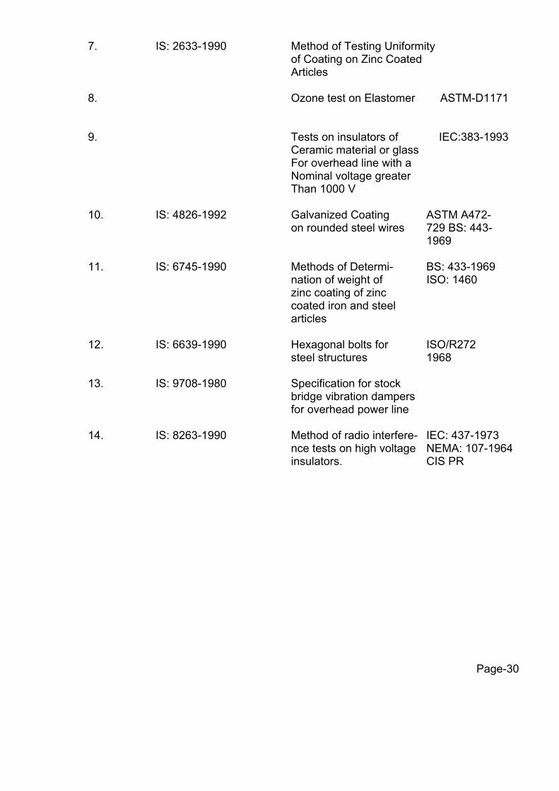
7. IS: 2633-1990 Method of Testing Uniformity of Coating on Zinc Coated Articles 8. Ozone test on Elastomer ASTM-D1171 9. Tests on insulators of IEC:383-1993 Ceramic material or glass For overhead line with a Nominal voltage greater Than 1000 V
10. IS: 4826-1992 Galvanized Coating ASTM A472- on rounded steel wires 729 BS: 443- 1969 11. IS: 6745-1990 Methods of Determi- BS: 433-1969 nation of weight of ISO: 1460 zinc coating of zinc coated iron and steel articles 12. IS: 6639-1990 Hexagonal bolts for ISO/R272 steel structures 1968 13. IS: 9708-1980 Specification for stock bridge vibration dampers for overhead power line 14. IS: 8263-1990 Method of radio interfere- IEC: 437-1973 nce tests on high voltage NEMA: 107-1964 insulators. CIS PR
Page-30

The standard mentioned above are available from: …………………………………………………………………………………………………… Reference Abbreviation Name and Address …………………………………………………………………………………………………… BS British Standards, British Standards Institution 101, Pentonvile Road, N-19-ND UK IEC/CISPR International Electrotechnical Commission, Bureau Central De la Commission, Electro Technique International, 1 Rue de verembe, Geneva Switzerland BIS/IS Bureau of Indian Standards, Mank Bhavan,-9, Bahadur Shah Zafar Marg, New Delhi 110001, INDIA ISO International Organisation for Standardization, Danish Board Of Standardization Danish
Standardising Sraat, Aurehoegvej- 12 DK-2900, Heeleprup, DENMARK.
NEMA National Electric Manufacture
Association, 155, East 44th Street,
New York, NY 10017 U.S.A.
Page-31

ANNEXURE-A TYPE TEST
1.0 Test on Complete Strings with Hardware Fittings 1.1 Voltage Distribution Test for Insulator String with Disc Insulators
The voltage across each insulator unit shall be measured by sphere gap method. The result obtained shall be converted into percentage. The voltage across any disc shall not exceed 20% for suspension insulator strings and 22% for tension insulator strings.
1.2 Mechanical Strength Test
The complete insulator string along with its hardware fitting excluding arcing horns and suspension assembly/dead end assembly shall be subjected to a load equal to 50% of the specified minimum ultimate tensile strength (UTS) which shall be increased at a steady rate to 67% of the minimum UTS specified. The load shall be held for five minutes and then removed. After removal of the load, the string components shall not show any visual deformation and it shall be possible to disassemble them by hand. Hand tools may be used to remove cotter pins and loosen the nuts initially. The string shall then be reassembled and loaded to 50% of UTS and the load shall be further increased at a steady rate till the specified minimum UTS and held for one minute. No fracture should occur during this period. The applied load shall then be increased until the failing load is reached and the value recorded.
1.3 Vibration Test
The suspension string shall be tested in suspension mode, and tension string in tension mode itself in laboratory span of minimum 30 metres. In the case of suspension string a load equal to 600 kg shall be applied along the axis of the suspension string by means of turn buckle. The insulator string along with hardware fittings and conductors tensioned at 2530 kgf in respect of 132kV strings with ACSR Panther Conductor shall be secured with clamps. The system shall be suitable to maintain constant tension on conductor throughout the duration of the test. Vibration dampers shall not be used on the test span. The conductor shall be vertically vibrated at one of the resonance frequencies of the insulators string (more than 10 Hz) by means of vibration inducing equipment. The peak to peak, displacement in mm of vibration at the antinode point nearest to the string shall be measured and the same shall not be less than 1000/f 1.8 where f is the frequency of vibration in cycles/sec. The insulator string shall be vibrated for not less than 10 million cycles without any failure. After the test the disc insulators shall be examined for looseness of pins and cap or any crack in the cement. The hardware shall be examined for looseness, fatigue failure and mechanical strength test. There shall be no deterioration of properties of hardware components and insulators after the vibration test. The insulators shall be subjected to the following tests as per relevant standards:
Page-32

Tests Percentage of insulator Units to be tested Disc a) Temperature cycle test 60 followed by mechanical performance test b) Puncture test 40
2. Tests on Hardware Fittings
2.1 Magnetic Power Loss Test for Suspension Assembly
One hollow aluminum tube of diameter equivalent to conductor Dia shall be placed. An alternating current over the range of 200 to 500 amps for ACSR Panther shall be passed through the tube. The reading of the wattmeter with and without suspension assemblies shall be recorded. Not less than three suspension assemblies shall be tested. The average power loss for suspension assembly shall be plotted for each value of current. The value of the loss corresponding to 350 amperes for 132kV Suspension assembley shall be read off from the graph.
2.2 Galvanising/Electroplating Test
The test shall be carried out as per Clause no. 5.9 of IS: 2486 (Part-I) 1972 except that both uniformity of zinc coating and standard preece test shall be carried out and the results obtained shall satisfy the requirements of this specification.
2.3 Mechanical Strength Test of Each Component
Each component shall be subjected to a load equal to the specified minimum ultimate tensile strength (UTS) which shall be increased at a steady rate to 67% of the minimum UTS specified. The load shall be held for five minutes and then removed. The component shall then again be loaded to 50% of UTS and the load shall be further increased at a steady rate till the specified UTS and held for one minute. No fracture should occur. The applied load shall then be increased until the failing load is reached and the value recorded.
2.4 Mechanical Strength Test of Welded Joint
The welded portion of the component shall be subjected to a Load of 2000 kgs for one minute. Thereafter, it shall be subjected to die penetratration/ultrasonic test. There shall not be any crack at the welded portion.
Page-33

2.5 Clamp Slip Strength Vs Torque Test for Suspension Clamp
The suspension assembly shall be vertically suspended by means of a flexible attachment. A suitable length of Conductor shall be fixed in the clamp. The clamp slip strength at various tightening torques shall be obtained by gradually applying the load at one end of the conductor. The clamp slip strength vs torque curve shall be drawn. The above procedure is applicable only for free centre type suspension clamp. For AG suspension clamp only clamp slip strength after assembly shall be found out. The clamp slip strength at the recommended tightening torque shall be more than 11 kN but less than 16 kN.
2.6 Shore Hardness Test for Elastomer Cushion for AG Suspension Assembly The shore hardness at various points on the surface of the elastomer cushion shall
be measured by a shore hardness meter and the shore hardness number shall be between 65 to 80.
2.7 Proof Load Test Each component shall be subjected to a load equal to 50% of the specified minimum
ultimate tensile strength which shall be increased at a steady rate to 67% of the minimum UTS specified. The load shall be held for one minute and then removed. After removal of the load the component shall not show any visual deformation.
2.8 Tests for Forging Casting and Fabricated Hardware The chemical analysis, hardness test, grain size, inclusion rating and magnetic
particle inspection for forging, castings and chemical analysis and proof load test for fabricated hardware shall be as per the internationally recognized procedures for these tests. The sampling will be based on heat number and heat treatment batch. The details regarding test will be as in the Quality Assurance programme.
2.9 Mechanical Strength Test for Suspension/Tension Hardware Fittings The complete string without insulators excluding arcing horn, and suspension
assembly/dead end assembly shall be subjected to a load equal to 50% of the specified minimum ultimate tensile strength (UTS) which shall be increased at a steady rate to 67% of the minimum UTS specified. This load shall be held for five minutes and then removed. After removal of the load, the string component shall not show any visual deformation and it shall be possible to disassemble them by hand. Hand tools may be used to remove cotter pins and loosen the nuts initially. The string shall then be reassembled and loaded to 50% of UTS and the load shall be further increased at a steady rate till the specified minimum UTS is reached and held for the one minute. No fracture should occur during this period. The applied load shall then be increased until the failing load is reached and the value recorded.
2.10 Ozone Test for Elastomer
This test shall be performed in accordance with ASTM D-1171 by the Ozone chamber exposure method (method B). The test duration shall be 500 hours and the ozone concentration 50 PPHM. At the test completion, there shall be no visible crack under a 2 x magnification.
Page-34
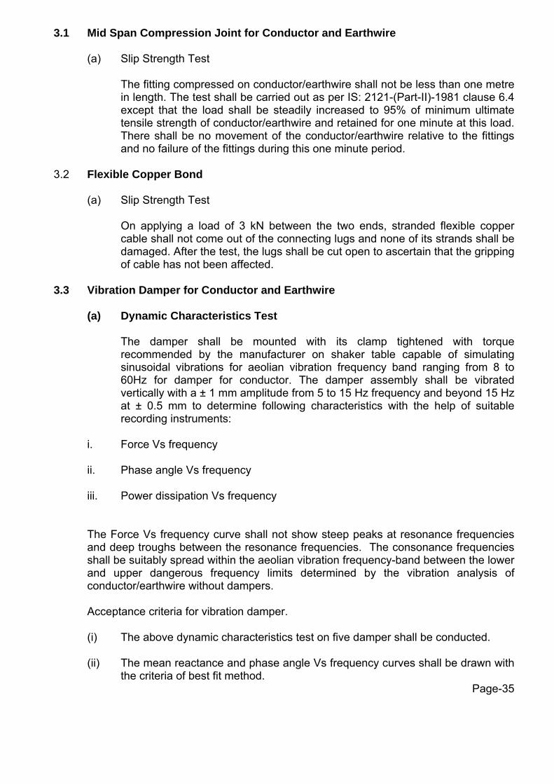
3.1 Mid Span Compression Joint for Conductor and Earthwire
(a) Slip Strength Test
The fitting compressed on conductor/earthwire shall not be less than one metre in length. The test shall be carried out as per IS: 2121-(Part-II)-1981 clause 6.4 except that the load shall be steadily increased to 95% of minimum ultimate tensile strength of conductor/earthwire and retained for one minute at this load. There shall be no movement of the conductor/earthwire relative to the fittings and no failure of the fittings during this one minute period.
3.2 Flexible Copper Bond
(a) Slip Strength Test
On applying a load of 3 kN between the two ends, stranded flexible copper cable shall not come out of the connecting lugs and none of its strands shall be damaged. After the test, the lugs shall be cut open to ascertain that the gripping of cable has not been affected.
3.3 Vibration Damper for Conductor and Earthwire
(a) Dynamic Characteristics Test
The damper shall be mounted with its clamp tightened with torque recommended by the manufacturer on shaker table capable of simulating sinusoidal vibrations for aeolian vibration frequency band ranging from 8 to 60Hz for damper for conductor. The damper assembly shall be vibrated vertically with a ± 1 mm amplitude from 5 to 15 Hz frequency and beyond 15 Hz at ± 0.5 mm to determine following characteristics with the help of suitable recording instruments:
i. Force Vs frequency
ii. Phase angle Vs frequency
iii. Power dissipation Vs frequency
The Force Vs frequency curve shall not show steep peaks at resonance frequencies and deep troughs between the resonance frequencies. The consonance frequencies shall be suitably spread within the aeolian vibration frequency-band between the lower and upper dangerous frequency limits determined by the vibration analysis of conductor/earthwire without dampers.
Acceptance criteria for vibration damper.
(i) The above dynamic characteristics test on five damper shall be conducted.
(ii) The mean reactance and phase angle Vs frequency curves shall be drawn with the criteria of best fit method.
Page-35

(iii) The above mean reactance response curve should lie within 0.099f to 0.495f Kgf/mm limits for ACSR Panther conductor damper
(iv) The above mean phase angle response curve shall be between 250 to 1300
within the frequency range of interest.
(v) If the above curve lies within the envelope, the damper design shall be considered to have successfully met the requirement.
(vi) Visual resonance frequencies of each mass of damper is to be recorded and to
be compared with the guaranteed values.
(b) Vibration Analysis
The vibration analysis of the conductor/earthwire shall be done with and without damper installed on the span. The vibration analysis shall be done on a digital computer using energy balance approach. The following parameters shall be taken into account for the purpose of analysis:
(i) The analysis shall be done for single conductor/earthwire without
armour rods as per the parameters given under clause 2.4.13 and 3.3.8 of this part of the Specification. The tension shall be taken as 2530 kgf for ACSR Panther for a span ranging from 100m to 1100m.
(ii) The self damping factor and flexural stiffness (EI) for conductor shall be
calculated on the basis of experimental results. The details for experimental analysis with these data should be furnished.
(iii) The power dissipation curve obtained from Dynamic Characteristics
Test shall be used for analysis with damper. (iv) Examine the Aeolian vibration level of the conductor/earthwire with and
without vibration damper installed at the recommended location or wind velocity ranging from 0 to 30 Km per hour, predicting amplitude, frequency and vibration energy input.
(v) From vibration analysis of conductor without damper, antinode vibration
amplitude and dynamic strain levels at clamped span extremities as well as antinodes shall be examined and thus lower and upper dangerous frequency limits between which the Aeolian vibration levels exceed the specified limits shall be determined.
(vi) From vibration analysis of conductor with damper/dampers installed at
the recommended location, the dynamic strain level at the clamped span extremities, damper attachment point and the antinodes on the conductor/earthwire shall be determined. In addition to above damper clamp vibration amplitude and antinode vibration amplitudes shall also be examined.
The dynamic strain levels at damper attachment points, clamped span extremities and antinodes shall not exceed the specified limits. The damper clamp vibration amplitude shall not be more than that of the specified fatigue limits.
Page-36
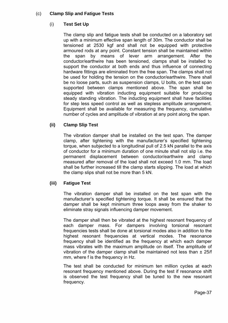
(c) Clamp Slip and Fatigue Tests
(i) Test Set Up
The clamp slip and fatigue tests shall be conducted on a laboratory set up with a minimum effective span length of 30m. The conductor shall be tensioned at 2530 kgf and shall not be equipped with protective armoured rods at any point. Constant tension shall be maintained within the span by means of lever arm arrangement. After the conductor/earthwire has been tensioned, clamps shall be installed to support the conductor at both ends and thus influence of connecting hardware fittings are eliminated from the free span. The clamps shall not be used for holding the tension on the conductor/earthwire. There shall be no loose parts, such as suspension clamps, U bolts, on the test span supported between clamps mentioned above. The span shall be equipped with vibration inducting equipment suitable for producing steady standing vibration. The inducting equipment shall have facilities for step less speed control as well as stepless amplitude arrangement. Equipment shall be available for measuring the frequency, cumulative number of cycles and amplitude of vibration at any point along the span.
(ii) Clamp Slip Test
The vibration damper shall be installed on the test span. The damper clamp, after tightening with the manufacturer’s specified tightening torque, when subjected to a longitudinal pull of 2.5 kN parallel to the axis of conductor for a minimum duration of one minute shall not slip i.e. the permanent displacement between conductor/earthwire and clamp measured after removal of the load shall not exceed 1.0 mm. The load shall be further increased till the clamp starts slipping. The load at which the clamp slips shall not be more than 5 kN.
(iii) Fatigue Test
The vibration damper shall be installed on the test span with the manufacturer’s specified tightening torque. It shall be ensured that the damper shall be kept minimum three loops away from the shaker to eliminate stray signals influencing damper movement. The damper shall then be vibrated at the highest resonant frequency of each damper mass. For dampers involving torsional resonant frequencies tests shall be done at torsional modes also in addition to the highest resonant frequencies at vertical modes. The resonance frequency shall be identified as the frequency at which each damper mass vibrates with the maximum amplitude on itself. The amplitude of vibration of the damper clamp shall be maintained not less than ± 25/f mm, where f is the frequency in Hz. The test shall be conducted for minimum ten million cycles at each resonant frequency mentioned above. During the test if resonance shift is observed the test frequency shall be tuned to the new resonant frequency.
Page-37
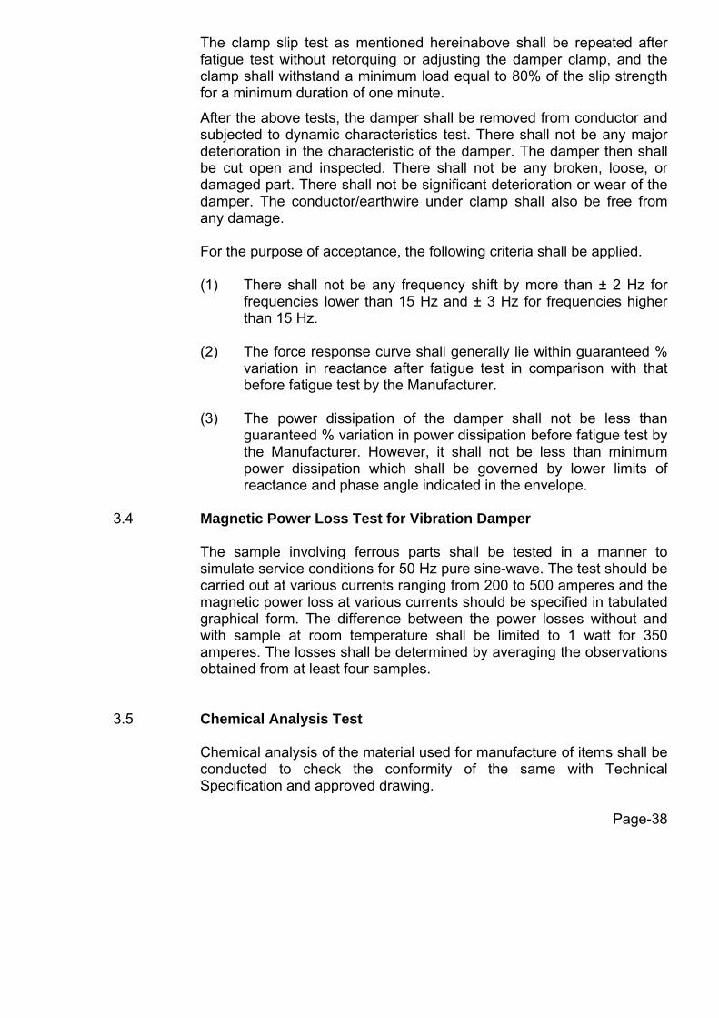
The clamp slip test as mentioned hereinabove shall be repeated after fatigue test without retorquing or adjusting the damper clamp, and the clamp shall withstand a minimum load equal to 80% of the slip strength for a minimum duration of one minute.
After the above tests, the damper shall be removed from conductor and subjected to dynamic characteristics test. There shall not be any major deterioration in the characteristic of the damper. The damper then shall be cut open and inspected. There shall not be any broken, loose, or damaged part. There shall not be significant deterioration or wear of the damper. The conductor/earthwire under clamp shall also be free from any damage.
For the purpose of acceptance, the following criteria shall be applied.
(1) There shall not be any frequency shift by more than ± 2 Hz for frequencies lower than 15 Hz and ± 3 Hz for frequencies higher than 15 Hz.
(2) The force response curve shall generally lie within guaranteed %
variation in reactance after fatigue test in comparison with that before fatigue test by the Manufacturer.
(3) The power dissipation of the damper shall not be less than
guaranteed % variation in power dissipation before fatigue test by the Manufacturer. However, it shall not be less than minimum power dissipation which shall be governed by lower limits of reactance and phase angle indicated in the envelope.
3.4 Magnetic Power Loss Test for Vibration Damper
The sample involving ferrous parts shall be tested in a manner to simulate service conditions for 50 Hz pure sine-wave. The test should be carried out at various currents ranging from 200 to 500 amperes and the magnetic power loss at various currents should be specified in tabulated graphical form. The difference between the power losses without and with sample at room temperature shall be limited to 1 watt for 350 amperes. The losses shall be determined by averaging the observations obtained from at least four samples.
3.5 Chemical Analysis Test
Chemical analysis of the material used for manufacture of items shall be conducted to check the conformity of the same with Technical Specification and approved drawing.
Page-38

4. Test on All components (As applicable)
4.1 Chemical Analysis of Zinc used for Galvanizing
Samples taken from the zinc ingot shall be chemically analysed as per IS: 209-1979. The purity of zinc shall not be less than 99.95%.
4.2 Tests for Forgings
The chemical analysis, hardness tests and magnetic particle inspection for forgings, will be as per the internationally recognized procedures for these tests. The sampling will be based on heat number and heat treatment batch. The details regarding test will be as discussed and mutually agreed to by the Manufacturer and HVPNL in Quality Assurance Programme.
4.3 Tests on Castings
The chemical analysis, mechanical and metallographic tests and magnetic particle inspection for castings will be as per the internationally recognized procedures for these tests. The samplings will be based on heat number and heat treatment batch. The details regarding test will be as discussed and mutually agreed to by the Manufacturer and HVPNL in Quality Assurance Programme.
Page-39

ANNEXURE-B
Acceptance Tests 1. Mid Span Compression Joint for Conductor and Earthwire (a) Hardness Test
The Brinnel hardness at various points on the steel sleeve of conductor core and of the earthwire compression joint and tension clamp shall be measured.
2. Flexible Copper Bond (b) Slip Strength Test Same as clause 3.2 (a) of Annexure-A. 3. Vibration Damper for Conductor and Earthwire (a) Verification of Reasonance Frequencies
The damper shall be mounted on a shaker table and vibrate at damper clamp displacement of +/0.5 mm to determine the resonance frequencies. The resonance shall be visually identified as the frequency at which damper mass vibrates with maximum displacement on itself. The resonance frequency thus identified shall be compared with the guaranteed value. A tolerance of ± 1 Hz at a frequency lower than 15 Hz and ± 2 Hz at a frequency higher than 15 Hz only shall be allowed.
(b) Clamp Slip Test Same as Clause 3.3 (c) (ii) of Annexure –A.
(c) Clamp Bolt Torque Test
The clamp shall be attached to a section of the conductor/earthwire. A torque of 150 % of the manufacturer’s specified torque shall be applied to the bolt. There shall be no failure of component parts. The test set up is as described in Clause 3.3 (c) (i), Annexure-A.
(d) Strength of the Messenger Cable
The messenger cable shall be fixed in a suitable tensile testing machine and the tensile load shall be gradually applied until yield point is reached. The load shall be not less than the value guaranteed by the Manufacturer.
Page-40

(e) Mass Pull of Test
Each mass shall be pulled off in turn by fixing the mass in one jaw and the clamp in the other of a suitable tensile testing machine. The longitudinal pull shall be applied gradually until the mass begins to pull out of the messenger cable. The pull off loads shall not be less than the value guaranteed by the Manufacturer.
(f) Dynamic Characteristics Test
The test will be performed as acceptance test with the procedure mentioned for type test with sampling mentioned below: -
Vibration Damper of Conductor
- 1 Sample for 1000 Nos. & below.
- 3 Samples for lot above 1000 & up to 5000 nos.
- Additional 1 sample for every additiona
1500 pieces above 5000.
The Acceptance criteria will be as follows :
(i) The above dynamic characteristics curve for reactance & phase angle will be done for frequency range of 8 Hz to 60 Hz for vibration damper for conductor
(ii) If all the individual curve for dampers are within the envelope as already
mentioned for type test for reactance & phase angle, the lot passes the test.
(iii) If individual results do not fall within the envelope, averaging of
characteristics shall be done.
(a) Force of each damper corresponding to particular frequency shall be taken & average force of three dampers at the frequency calculated.
(b) Similar averaging shall be done for phase angle.
(c) Average force Vs frequency and average phase Vs frequency
curves shall be plotted on graph paper. Curves of best fit shall be drawn for the entire frequency range.
(d) The above curves shall be within the envelope specified.
Page-41

STANDARD FIELD QUALITY PLAN FOR TRANSMISSION LINES page 1
Check/Testing S.
No.
Description of
Activity
Items to be Checked Tests/Checks to be
done
Ref. documents
Agency Extent
Counter Check/Test by HVPNL Accepting
authority
1. Detailed Survey a. Route alignment Optimization of route
length
a. Preliminary survey.
b. Topographical map
c. Tower spotting data
Bidder
100% at Field
100% based on record documents
Engineer-in-
charge of HVPNL
b. Route profiling &
tower spotting.
1. Ground clearance. 2. Cold wt. Span 3. Hot wt. Span 4. Sum of Adj. Span
(wind span) 5. Angle of
Deviation.
a. Sag template
b. Tower Spotting data
c. Route alignment
Bidder
-do-
-do-
-do-
-do-
100% at Field
-do-
-do-
-do-
-do-
100% based on record documents
-do-
-do-
-do-
Engineer-in-
charge of HVPNL
2. Check Survey Tower Location &
Final Length
i) Alignment
ii) Final Length
a. Route alignment
b. Tower Schedule
c. Profile
Bidder
-do-
100% at Field
-do-
i) All angle towers in plains and 50% in hilly terrains.
ii) Final length to be checked on 100% basis based on records/documents
Engineer-in-
charge of HVPNL
3. Tower Foundation
A. Materials 1. Cement
( 43 grade) as per
Annexure-A
1. Source approval Source meeting HVPNL Specification/Approved vendor
Bidder As proposed by Bidder To verify the proposal based on the supply made and factory test results.
Engineer-in-
charge of HVPNL
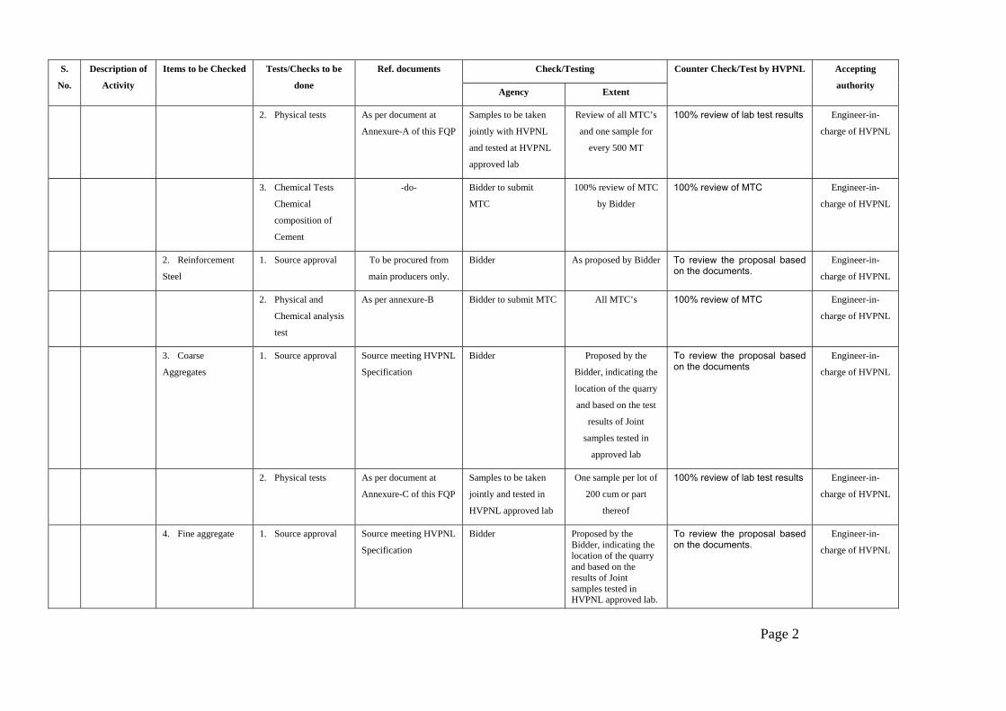
Check/Testing S.
No.
Description of
Activity
Items to be Checked Tests/Checks to be
done
Ref. documents
Agency Extent
Counter Check/Test by HVPNL Accepting
authority
2. Physical tests As per document at
Annexure-A of this FQP
Samples to be taken
jointly with HVPNL
and tested at HVPNL
approved lab
Review of all MTC’s
and one sample for
every 500 MT
100% review of lab test results Engineer-in-
charge of HVPNL
3. Chemical Tests
Chemical
composition of
Cement
-do- Bidder to submit
MTC
100% review of MTC
by Bidder
100% review of MTC Engineer-in-
charge of HVPNL
2. Reinforcement
Steel
1. Source approval To be procured from
main producers only.
Bidder As proposed by Bidder To review the proposal based on the documents.
Engineer-in-
charge of HVPNL
2. Physical and
Chemical analysis
test
As per annexure-B Bidder to submit MTC All MTC’s 100% review of MTC Engineer-in-
charge of HVPNL
3. Coarse
Aggregates
1. Source approval Source meeting HVPNL
Specification
Bidder Proposed by the
Bidder, indicating the
location of the quarry
and based on the test
results of Joint
samples tested in
approved lab
To review the proposal based on the documents
Engineer-in-
charge of HVPNL
2. Physical tests As per document at
Annexure-C of this FQP
Samples to be taken
jointly and tested in
HVPNL approved lab
One sample per lot of
200 cum or part
thereof
100% review of lab test results Engineer-in-
charge of HVPNL
4. Fine aggregate 1. Source approval Source meeting HVPNL
Specification
Bidder Proposed by the Bidder, indicating the location of the quarry and based on the results of Joint samples tested in HVPNL approved lab.
To review the proposal based on the documents.
Engineer-in-
charge of HVPNL
Page 2

Check/Testing S.
No.
Description of
Activity
Items to be Checked Tests/Checks to be
done
Ref. documents
Agency Extent
Counter Check/Test by HVPNL Accepting
authority
2. Physical test As per Annexure-D of
this FQP
Samples to be taken
jointly and tested in
HVPNL approved lab
One sample per lot of
200 cum or part
thereof
100% review of lab test results Engineer-in-
charge of HVPNL
5. Water 1. Cleanliness (Water
shall be fresh ,
clean and potable)
HVPNL Specification Bidder 100% visual check at
Field
1. Verification at random
2. Lab. test before start of work
from approved Lab.
Engineer-in-
charge of HVPNL
2. Suitability of water
for concreting
HVPNL Specification Bidder 100% Visual Check
at Field
1. Verification at random
2. Lab. test before start of work
from approved Lab.
Engineer-in-
charge of HVPNL
B. Foundation Classification
1. Visual observation
of soil strata
2. Ground water level
3. History of water
table in adj.
Area/surface water
4. Soil Investigation
wherever required.
5 Crop pattern
HVPNL Specification Bidder 100% at Field 100% at Field
Engineer-in-
charge of HVPNL
C. Concrete Works a. Before concreting
1. Bottom of excavated earth
Depth of foundation Appd. Drgs. Bidder 100% at Field 100% check by HVPNL Engineer-in-
charge of HVPNL
2. Stub setting 1) Centre Line -do- -do- -do- -do- -do-
2) Diagonals
3. Reinforcement steel
3) Level of stubs
b. During concreting
Placement Bar bending schedule -do- -do- -do- -do-
Page 3

Check/Testing S.
No.
Description of
Activity
Items to be Checked Tests/Checks to be
done
Ref. documents
Agency Extent
Counter Check/Test by HVPNL Accepting
authority
1. Workability Slump test As per HVPNL
Specification and
document at Annexure-
E of this FQP
Bidder 100% at field 20% check at random Engineer-in-
charge of HVPNL
2. Concrete
Strength
Cubes Comp Strength As per HVPNL
Specification and
document at Annexure-
E of this FQP
Casting of cubes at site.
Cubes to be tested at
HVPNL appd. Lab for 7
days & 28 days strength
One sample of 6
cubes in each
tower locations
100% review of lab test results. Cubes at 20% location are to be taken in presence of
HVPNL officials
Engineer-in-
charge of HVPNL
4. Tower
Erection
1. Materials
a. Tower
member/bolts &
nuts/washers/acces
sories
Visual checking for
1. Stacking
2. Cleanliness
3. Galvanizing
4. Damages
Appd. Drgs./BOM Bidder 100% at stores 100% verification of records
Engineer-in-
charge of HVPNL
2. Erection of
Super-structure
1. Sequence of
erection
As per approved
Drgs./HVPNL
specification
Bidder 100% at field 100% check Engineer-in-
charge of HVPNL
2. Check for
completeness
-do- -do- -do- -do- -do-
3. Tightening of
nuts and bolts
-do- -do- -do- -do- -do-
4. Check for
verticality
-do- -do- -do- -do- -do-
5. Tack welding for bolts & nuts
HVPNL Specification Bidder 100% at Field 100% Check ---do---
3. Tower footing
resistance (TFR)
TFR at locations before and after earthing.
HVPNL Specification Bidder 100% at Field 20% locations to be verified
---do---
Page-4

Check/Testing S.
No.
Description of
Activity
Items to be Checked Tests/Checks to be
done
Ref. documents
Agency Extent
Counter Check/Test by HVPNL Accepting
authority
5. Stringing 1. Materials
a. Insulators 1. Visual check for cleanliness/glazing/cracks/and white spots.
HVPNL Specification Bidder 100% at Field 100% verification of records and to carry random checks 10%
Engineer-in-
charge of HVPNL
2. IR Value (min. 50M Ohms) -do- One test per sample
size of 20 for every
lot of 10,000
To verify Bidder’s records 100% and joint check 20% of total tests
-do-
3. E&M test - Insulator supplier a. 20 per 10,000 for
discs
b. 3 per 1500 for long rod
Collection of samples, sealing them and handing over by HVPNL to Insulator supplier
Inspecting officer of HVPNL
Traceability(Make/batch No./Locations where installed)
Packing list/CIP Bidder 100% at field 100% Review of records
Engineer-in-charge of HVPNL
b. Conductor On receipt, 1. Visual check of drum.
Packing list Bidder 100% at stores 20% check Engineer-in-charge of HVPNL
2. Check for seals at both ends, and HVPNL sticker on outer end
-do- -do- -do- -do- -do-
3. Check depth from top of flange to the top of the outer most layer
-do- -do- -do- -do- -do-
c. Earthwire Check for seals at both ends
Packing list Bidder 100% at stores 20% check -do-
2. Field activity
a. Before Stringing
Readiness for stringing
Stringing procedures as per HVPNL specification
Bidder Readiness certificate to be submitted by the Bidder
Review of Certificate Engineer-in-charge of HVPNL
b. During stringing
(Conductor/Earth-wire)
Page 5

Check/Testing S.
No.
Description of
Activity
Items to be Checked Tests/Checks to be
done
Ref. documents
Agency Extent
Counter Check/Test by HVPNL Accepting
authority
1. Scratch/cut
check (Visual)
Appd. Drawings/
HVPNL Specn.
Bidder 100% at Field 100% record & Field check 20%
Engineer-in-
charge of HVPNL
2. Repair sleeve -do- -do- -do- -do- -do-
3. Mid span Joints -do- -do- -do- -do- -do-
4. Guying (in case
of towers not
designed for one
side stringing)
Appd. Guying
arrangement/HVPNL
specn.
-do- -do- 100% Engineer-in-
charge of HVPNL
c. After stringing Check for,
1. Sag/Tension Sag tension
chart/tower Spotting
data
-do- -do- 100% record & Field check 20%
Engineer-in-
charge of HVPNL
2. Electrical
clearances
As per appd.
Drgs./HVPNL
specifications
-do- -do- -do- -do-
i) Ground
clearance
-do- -do- -do- -do- -do-
ii) Live metal
clearance etc.
-do- -do- -do- -do- -do-
3. Jumpering -do- -do- -do- -do- -do-
Page 6

Check/Testing S.
No.
Description of
Activity
Items to be Checked Tests/Checks to be
done
Ref. documents
Agency Extent
Counter Check/Test by HVPNL Accepting
authority
4. Copper bond As per Appd.
Drgns./HVPNL
Specification
Bidder 100% at Field 100% record & Field Check 20%
Engineer-in-
charge of HVPNL
5. Placement of
spacer/damper
As per Specn./drgs/
placement chart
-do- -do- -do- -do-
6. Final Testing
a. Pre-
commissionin
g of lines
a. Readiness of
lines for pre-
commissioning
1. Completeness of
line.
2. Meggar test of
line
Refer pre
commissioning
Check list & testing
of EHV lines for
charging formats
attached with this
FQP
Bidder 100% 100% joint checking Engineer-in-
charge of HVPNL
b. Commi-
ssioning of
line
Readiness of lines
for commissioning
- a. Owner latest pre-commissioning
procedures . As per annexure enclosed.
b. Pre-
commissioning
Report
c. CEA clearance
-do- -do- -do- -do-
3. Electrical Inspectors clearance from CEA.
-do- -do- -do- -do-
Page 7

Annexure A ACCEPTANCE CRITERIA AND PERMISSIBLE LIMITS FOR CEMENT
ORDINARY PORTLAND CEMENT
S. No.
Name of the test Ordinary Portland Cement 43 grade as per IS 8112
Remarks
a) Physical tests
(i) Fineness
Specific surface area shall not be less than 225 sq.m. per Kg or 2250 Cm2/gm.
(ii) Compressive strength
72+/- 1 hour : Not less than 23 Mpa (23 N/mm2)
168+/-2 hour : Not less than 33 Mpa (33 N/mm2)
672+/-4 hour : Not less than 43 Mpa (43 N/mm2)
(iii) Initial & Final setting time
Initial setting time : Not less than 30 minutes
Final setting time : Not more than 600 minutes
(iv) Soundness Unaerated cement shall not have an expansion of more than 10mm when tested by Le chatlier and 0.8% Autoclave test
To be conducted in apprd. Lab on every lot of 500 MT.
Page 8
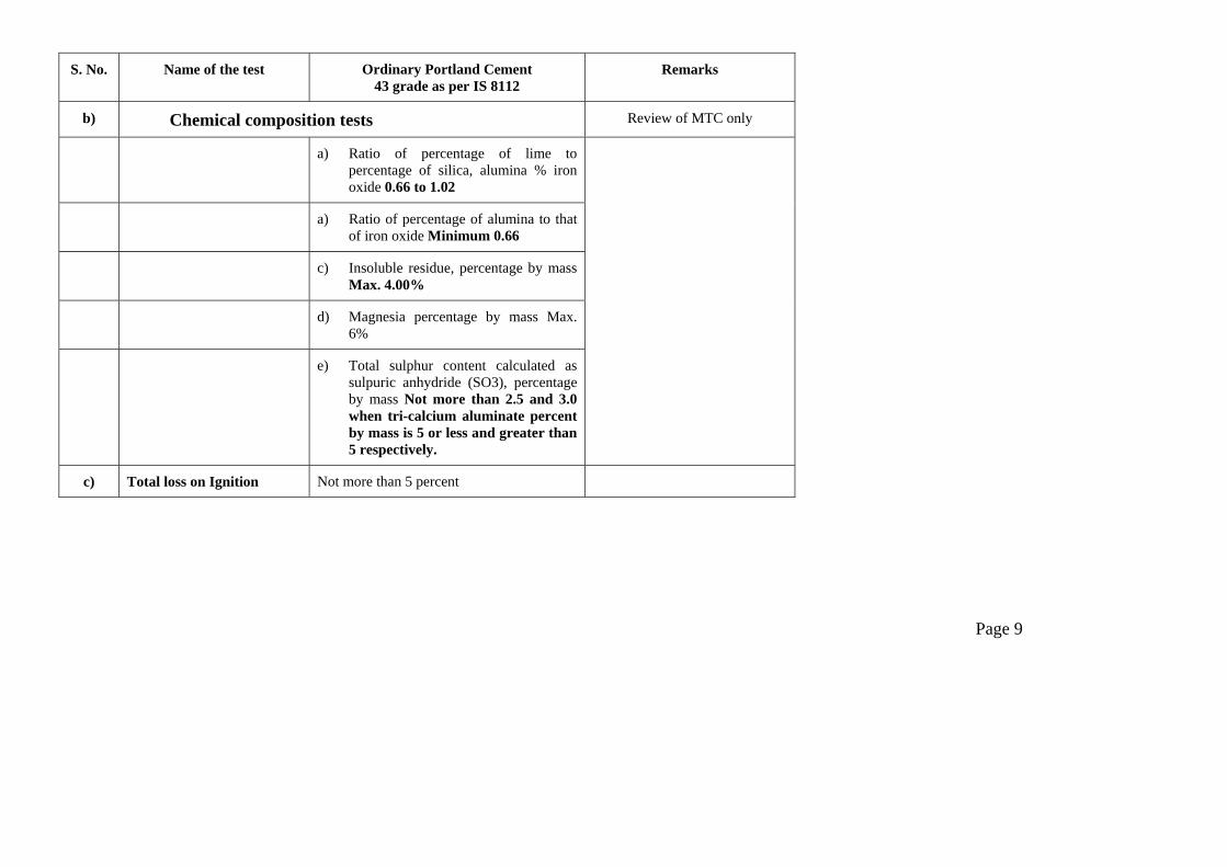
S. No. Name of the test Ordinary Portland Cement 43 grade as per IS 8112
Remarks
b) Chemical composition tests Review of MTC only
a) Ratio of percentage of lime to percentage of silica, alumina % iron oxide 0.66 to 1.02
a) Ratio of percentage of alumina to that of iron oxide Minimum 0.66
c) Insoluble residue, percentage by mass Max. 4.00%
d) Magnesia percentage by mass Max. 6%
e) Total sulphur content calculated as sulpuric anhydride (SO3), percentage by mass Not more than 2.5 and 3.0 when tri-calcium aluminate percent by mass is 5 or less and greater than 5 respectively.
c) Total loss on Ignition Not more than 5 percent
Page 9
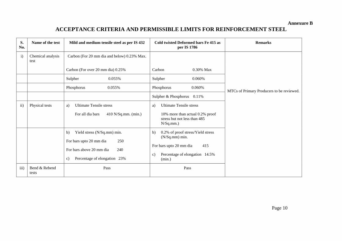
Annexure B
ACCEPTANCE CRITERIA AND PERMISSIBLE LIMITS FOR REINFORCEMENT STEEL
S. No.
Name of the test Mild and medium tensile steel as per IS 432 Cold twisted Deformed bars Fe 415 as per IS 1786
Remarks
i) Chemical analysis test
Carbon (For 20 mm dia and below) 0.23% Max.
Carbon (For over 20 mm dia) 0.25% Carbon 0.30% Max
Sulpher 0.055% Sulpher 0.060%
Phosphorus 0.055% Phosphorus 0.060%
Sulpher & Phosphorus 0.11%
ii) Physical tests a) Ultimate Tensile stress
For all dia bars 410 N/Sq.mm. (min.)
a) Ultimate Tensile stress
10% more than actual 0.2% proof stress but not less than 485 N/Sq.mm.)
b) Yield stress (N/Sq.mm) min.
For bars upto 20 mm dia 250
For bars above 20 mm dia 240
c) Percentage of elongation 23%
b) 0.2% of proof stress/Yield stress (N/Sq.mm) min.
For bars upto 20 mm dia 415
c) Percentage of elongation 14.5% (min.)
iii) Bend & Rebend tests
Pass Pass
MTCs of Primary Producers to be reviewed.
Page 10

Annexure C
ACCEPTANCE CRITERIA AND PERMISSIBLE LIMITS FOR COARSE AGGREGATES AS PER IS 383
3. Coarse Aggregates
i) Physical Tests
a) Determination of particles size
a. IS Sieve Designation
%age passing for Single-Sized Aggregate of nominal size
Percentage Passing for grades Aggregate of nominal size
40 mm 20 mm 16 mm 12.5 mm 10 mm
40 mm 20 mm 16 mm 12.5 mm
63 mm 100 - - - - - - - -
40 mm 85 to 100 100 - - - 95 to 100 100 - -
20 mm 0 to 20 85 to 100 100 - - 30 to 70 95 to 100 100 100
16 mm - - 85 to 100 100 - - - 90-100 -
12.5 mm - - - 85 to 100 100 - - - 90 to 100
10 mm 0 to 5 0 to 20 0 to 30 0 to 45 85 to 100
10 to 35 25 to 35 30 to 70 40 to 85
4.75 mm - 0 to 5 0 to 5 0 to 10 0 to 20
0 to 5 0 to 10 0 to 10 0 to 10
2.36 mm - - - - 0 to 5 - - - -
b. Flakiness index Not to exceed 25%
c. Crushing Value Not to exceed 45%
d. Presence of deleterious material Total presence of deleterious materials not to exceed 5%
e. Soundness test (for concrete work subject to frost action)
12% when tested with sodium sulphate and 18% when tested with magnesium sulphate
Page 11

Annexure D
ACCEPTANCE CRITERIA AND PERMISSIBLE LIMITS FOR FINE AGGREGATES AS PER IS 383
4. Fine aggregates
i) Physical Tests Percentage passing for graded aggregate of nominal size
a) Determination of particle size IS Sieve Designation F.A. Zone I F.A. Zone II F.A. Zone
III 10 mm 100 100 100
4.75 mm 90-100 90-100 90-100
2.36 mm 60-95 75-100 85-100
1.18 mm 30-70 55-90 75-100
600 microns 12.5 mm
15-34 35-59 60-79
300 microns 5 to 20 8 to 30 12 to 40
150 microns 0-10 0-10 01-0
b) Silt content Not to exceed 8%
Not to exceed 8%
Not to exceed 8%
c) Presence of deleterious material Total presence of deleterious materials shall not exceed 5%
d) Soundness Applicable to concrete work subject to frost action
12% when tested with sodium sulphate and 15% when tested with magnesium sulphate
Page 12

Annexure E ACCEPTANCE CRITERIA AND PERMISSIBLE LIMITS FOR CONCRETE WORK
1) Concrete a) Workability Slump shall be recorded by slump cone method and it shall between 50-75 mm.
as per site requirement. However the water cement ratio shall be maintained as per approved mix design.
b) Compressive strength Six samples of 15cm cubes, three for 7 days testing and balance three for 28 days testing shall be taken.
Notes : 1) For nominal (volumetric) concrete mixes, compressive strength for 1:1.5:3 (Sand : Fine aggreagates : Coarse aggregates) concrete shall
be 265 kg/Sq.cm. for 28 days and for 1:2:4 nominal mix, it shall be 210 kg/Sq.cm.
2) ACCEPTANCE CRITERIA BASED ON 28 DAYS COMPRESSIVE STRENGTHS FOR NOMINAL MIX CONCRETE :
a) the average of the strength of three specimen be accepted as the compressive strength of the concrete, provided the strength of any individual cube shall neither be less than 70% nor higher than 130% of the specified strength.
b) If the actual average strength of accepted sample exceeds specified strength by more than 30%, the Engineer-in-charge, if he so desires, may further investigate the matter. However, if the strength of any individual cube exceeds more than 30% of the specified strength, it will be restructed to 30% only for computation of strength.
c) If the actual average strength of accepted sample is equal to or higher than specified upto 30%, the strength of the concrete shall be considered in order and the concrete shall be accepted at full rates.
d) If the actual average strength of accepted sample is less than specified strength but not less than 70% of the specified strength, the concrete may be accepted at reduced rate at the discretion of Engineer-in-charge.
e) If the actual average strength of accepted sample is less than 70% of specified strength, the Engineer-in-charge shall reject the defective portion of work represent by sample and nothing shall be paid for the rejected work. Remedial measures necessary to retain the structure shall taken at the risk and cost of Bidder. If, however, the Engineer-in-charge so desires, he may order additional tests to be carried out to ascertain if the structure can be retained. All the charges in connection with these additional tests shall be borne by the Bidder.
Page 13

General Notes :
1. This standard Field Quality Plan is not to limit the supervisory checks which are otherwise required to be carried out during execution of work as per drawings/Technical specifications etc.
2. Bidder shall be responsible for implementing/documenting the SFQP. Documents shall be handed over by the Bidder to HVPNL after the completion of the work.
3. Project incharge means over all incharge of work. Line Incharge means incharge of the line. Section in-charge means incharge of the section.
4. In case of deviation the approving authority will be one step above the officer designated for acceptance in this quality plan subject to minimum level of Line incharge.
5. Acceptance criteria and permissible limits for tests are indicated in the Annexures. However for further details/tests HVPNL specification and relevant Indian standards shall be referred.
6. Tests as mentioned in this FQP shall generally be followed. However E.I.C. reserves the right to order additional tests wherever required necessary at the cost of the agency.
7. All counter checks/tests by HVPNL shall be carried out by HVPNL’s officials atleast at the level of Jr. Engr.
Page 14
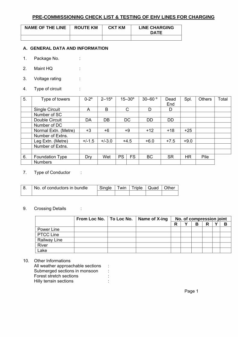
PRE-COMMISSIONING CHECK LIST & TESTING OF EHV LINES FOR CHARGING
NAME OF THE LINE ROUTE KM CKT KM LINE CHARGING DATE
A. GENERAL DATA AND INFORMATION 1. Package No.
:
2. Maint HQ
:
3. Voltage rating
:
4. Type of circuit : 5. Type of towers 0-2º 2–15º 15–30º 30–60 º Dead
End Spl. Others Total
Single Circuit A B C D D Number of SC Double Circuit DA DB DC DD DD Number of DC Normal Extn. (Metre) +3 +6 +9 +12 +18 +25 Number of Extns. Leg Extn. (Metre) +/-1.5 +/-3.0 +4.5 +6.0 +7.5 +9.0 Number of Extns. 6. Foundation Type Dry Wet PS FS BC SR HR Pile Numbers 7. Type of Conductor
:
Single Twin Triple Quad Other 8. No. of conductors in bundle
9. Crossing Details :
No. of compression joint From Loc No. To Loc No. Name of X-ing R Y B R Y B
Power Line PTCC Line Railway Line River Lake
10. Other Informations All weather approachable sections : Submerged sections in monsoon : Forest stretch sections : Hilly terrain sections : Page 1

11. Name of towns
along the line route Distance from line
(km) Approx. time to reach
Hr. Min. A. B. C. D. E. 12. Any other special features of the line : B. CHECK LIST ON CONSTRUCTION
STATUS S.NO. DESCRIPTION YES NO
REMARKS Record Deficiencies if any
1. FOUNDATION a. Check any damage/ uneven
settlement of foundation.
b. Check back filling of foundation is properly filled up to the ground level of all legs.
c. Check surface earth/ concrete after foundation casting is removed from platform of the tower to beyond a distance of 30 meters.
d. Check crack or break in chimney. e. Check coping is proper f. Check crack or damage to retaining
wall/ revetment and proper weep holes are provided for flushing water.
g. Check that all foundation chimneys are covered with soil and compacted specially in hilly terrain and river/ nalahs banks upto ground level.
2. TOWER a. Check for deformed/ rusted or
damaged tower members.
b. Check for missing tower members. c. Check for missing bolts & nuts. d. Check for tightening of all bolts &
nuts.
e. Check for punching, tack welding (at least 10 mm circular length) and zinc coating of bolts & nuts.
f. Check filling of blank holes in tower members with bolts & nuts.
g. Check verticality of tower. h. Check that no tower leg is suspected
to be in sinking land or soil erosion field of river bank, if so, proper and adequate protection has been provided.
Page-2

i. Check fixing of all tower accessories
namely step bolts, anti climbing device (ACD), earthing/ counterpoise-earthing.
j. Check visibility of danger/ number/ phase & circuit plate along longitudinal section of line.
k. Check correct sequence of fixing of phase/ circuit plate at transposition towers.
3. Removal of T&P and foreign materials a. Check temporary earthing/ guys used
during stringing and jumpering are removed.
b. Check all foreign materials on tower e.g. dense spider webs, any handling rod/ wire, kites, bird nests and left over T&P on tower/ cross arm are removed.
c. Check read and white paints on towers above 45m which fall in aviation route.
d. Check aviation warning signals on tall towers near Airport/ Airstrip as per rules.
4. Insulators a. Check that all insulator discs are free
from damage and clean.
b. Check for unusual deflection of suspension string.
c. Check whether verticality of string restored.
5. Hardware and accessory fittings a. Check that proper fixing of hardware
fittings like corona control ring/ arcing horns etc. are provided as per the approved drawing/ specification/
b. Check randomly the condition of cotter pins and ensure that proper size cotter pins have provided as per the approved drawing.
c. Check that the conductors/ sub-conductors are free from scratches/ rubs.
d. Check that all joints on conductor/ earth wire are away from the tower as per the specified distance (at least 30 meters) and joints are as per the approved drawings/ specification.
e. Check that not more than one joint in a sub-conductor is provided in one span.
Page 3
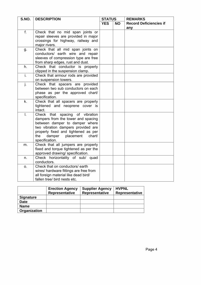
STATUS S.NO. DESCRIPTION YES NO
REMARKS Record Deficiencies if any
f. Check that no mid span joints or repair sleeves are provided in major crossings for highway, railway and major rivers.
g. Check that all mid span joints on conductors/ earth wire and repair sleeves of compression type are free from sharp edges, rust and dust.
h. Check that conductor is properly clipped in the suspension clamp.
i. Check that armour rods are provided on suspension towers.
j. Check that spacers are provided between two sub conductors on each phase as per the approved chart/ specification.
k. Check that all spacers are properly tightened and neoprene cover is intact.
l. Check that spacing of vibration dampers from the tower and spacing between damper to damper where two vibration dampers provided are properly fixed and tightened as per the damper placement chart/ specification.
m. Check that all jumpers are properly fixed and torque tightened as per the approved drawing/ specification.
n. Check horizontality of sub/ quad conductors.
o. Check that on conductors/ earth wires/ hardware fittings are free from all foreign material like dead bird/ fallen tree/ bird nests etc.
Erection Agency
Representative Supplier Agency Representative
HVPNL Representative
Signature Date Name Organization
Page 4
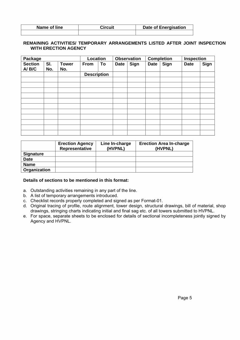
Name of line Circuit Date of Energisation REMAINING ACTIVITIES/ TEMPORARY ARRANGEMENTS LISTED AFTER JOINT INSPECTION
WITH ERECTION AGENCY Package Location Observation Completion Inspection Section A/ B/C
Sl. No.
Tower No.
From To Date Sign Date Sign Date Sign
Description Erection Agency
Representative Line In-charge
(HVPNL) Erection Area In-charge
(HVPNL) Signature Date Name Organization Details of sections to be mentioned in this format: a. Outstanding activities remaining in any part of the line. b. A list of temporary arrangements introduced. c. Checklist records properly completed and signed as per Format-01. d. Original tracing of profile, route alignment, tower design, structural drawings, bill of material, shop
drawings, stringing charts indicating initial and final sag etc. of all towers submitted to HVPNL. e. For space, separate sheets to be enclosed for details of sectional incompleteness jointly signed by
Agency and HVPNL.
Page 5

Name of line Circuit Line Section
HANDLING OVER RECORD FOR ENERGIZATION GENERAL STATUTORY ISSUES CHECK LIST Package Type of towers S/C D/C Voltage rating kV Tower locations From To Total no. of towers Total length Kms Details:
Status S. No. Description Yes No
Remarks Record deficiencies if any
1. Check list of entire section of the line along with towers and accessories under this division have carried out and documented in the format no.01.
2. Inspection has been carried out in all towers and the outstanding issues along with temporary arrangements are documented in the format no. 02.
3. No. of remaining activities/ points are listed below and these are minor in nature and do not stop charging the line.
Handing over check points
Points completed and confirmed
Points accepted Section Points according to format no. PTL/TL.Const./10/Format/10 (Nos. of remaining activities) Date Sign Date Sign
A B C D
Status S. No. Description Yes No
Remarks Record deficiencies if any
4. All electrical and ground clearances are as per the approved drawings issued from Engg. Dept. have been checked and no deviation has been noted.
5. All men and material and temporary antitheft electrical connection, if any, have been removed from all the locations under this division.
6. All electrical clearance has been received from CEA electrical inspector for charging of the line vide order no. dated (copy enclosed).
Page-6
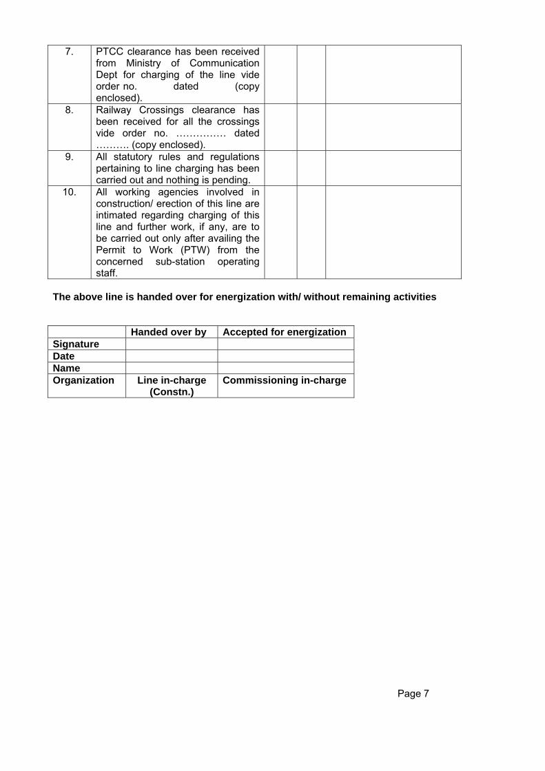
7. PTCC clearance has been received
from Ministry of Communication Dept for charging of the line vide order no. dated (copy enclosed).
8. Railway Crossings clearance has been received for all the crossings vide order no. …………… dated ………. (copy enclosed).
9. All statutory rules and regulations pertaining to line charging has been carried out and nothing is pending.
10. All working agencies involved in construction/ erection of this line are intimated regarding charging of this line and further work, if any, are to be carried out only after availing the Permit to Work (PTW) from the concerned sub-station operating staff.
The above line is handed over for energization with/ without remaining activities Handed over by Accepted for energization Signature Date Name Organization Line in-charge
(Constn.) Commissioning in-charge
Page 7

Name of line Circuit Date of charging
COMMISIONING FORMAT
GENERAL DATA AND INFORMATION Package Type of towers S/C D/C Voltage rating kV Tower locations From To Total no. of towers Total length Km
Status S. No. Description Yes No
Remarks Record deficiencies if any
1. The entire section of the line handed over for energization as per Powerlinks format no. 03 on dated……
2. No. of remaining activities/ points are listed as per format no. 02 and these are minor in nature and do not stop charging the line.
3. All the equipments involved in charging of the line are tested and documented as per the pre-commissioning formats of bay equipment.
4. Pre-commissioning tests of bay/ feeder as per approved document has been completed and test results are documented by substation in-charge.
5. In case reactor provided in this line all tests are carried out as per prescribed format and all test results are documented by substation in-charge.
6. All electrical clearance has been received from CEA electrical inspector for charging of the line vide order no. ………. Dated ……. (copy to be enclosed)
Page 8
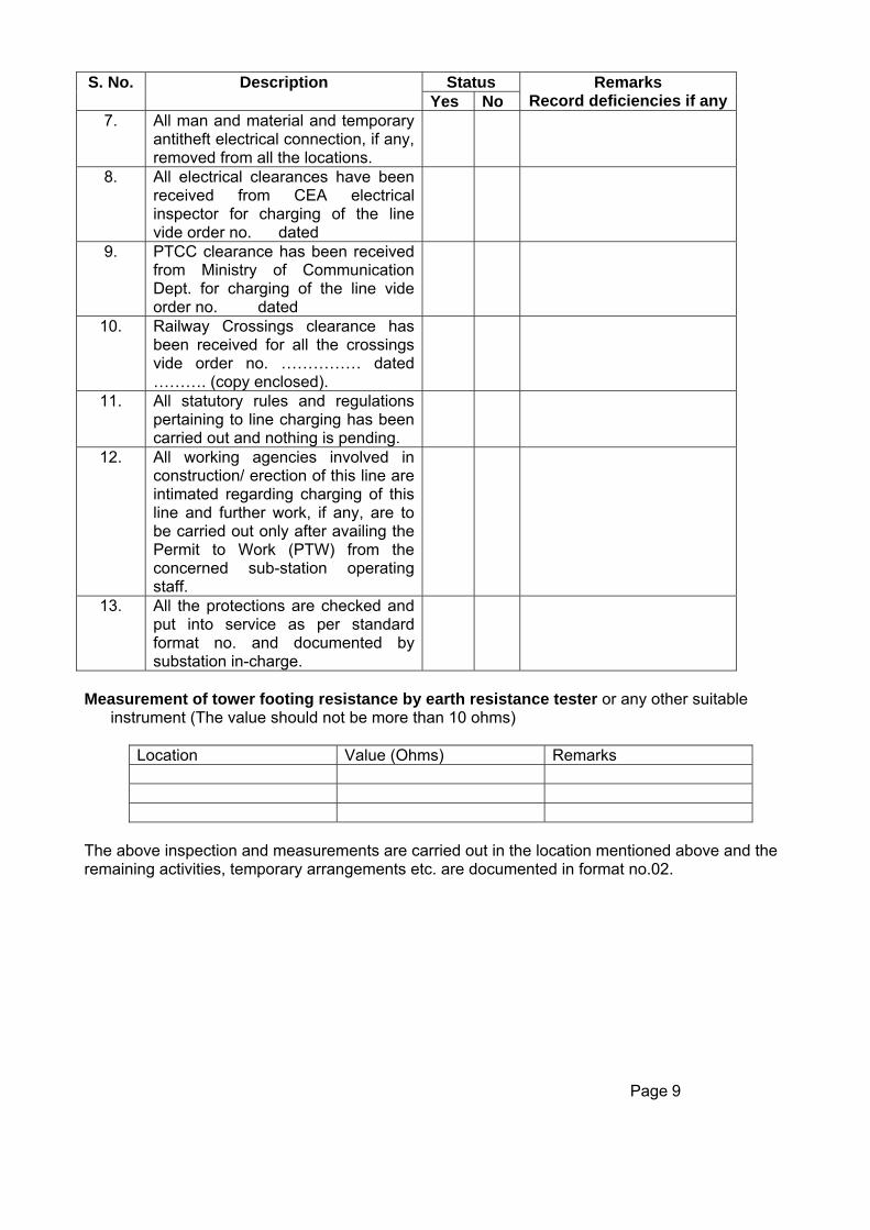
Status S. No. Description
Yes No Remarks
Record deficiencies if any7. All man and material and temporary
antitheft electrical connection, if any, removed from all the locations.
8. All electrical clearances have been received from CEA electrical inspector for charging of the line vide order no. dated
9. PTCC clearance has been received from Ministry of Communication Dept. for charging of the line vide order no. dated
10. Railway Crossings clearance has been received for all the crossings vide order no. …………… dated ………. (copy enclosed).
11. All statutory rules and regulations pertaining to line charging has been carried out and nothing is pending.
12. All working agencies involved in construction/ erection of this line are intimated regarding charging of this line and further work, if any, are to be carried out only after availing the Permit to Work (PTW) from the concerned sub-station operating staff.
13. All the protections are checked and put into service as per standard format no. and documented by substation in-charge.
Measurement of tower footing resistance by earth resistance tester or any other suitable
instrument (The value should not be more than 10 ohms)
Location Value (Ohms) Remarks
The above inspection and measurements are carried out in the location mentioned above and the remaining activities, temporary arrangements etc. are documented in format no.02. Page 9

MEASUREMENT OF INSULATION RESISTANCE FOR BUS BAR (using 5kV motorized megger)
BETWEEN MEASURED VALUE IN M –
OHM
REMARK CONDITION
R-PHASE & GROUND Y-PHASE & GROUND B-PHASE & GROUND
R-PHASE & Y-PHASE Y-PHASE & B-PHASE B-PHASE & R-PHASE
All breakers and isolators to be closed for section of the bus bar to be energized and all ground switches opened.
MEASUREMENT OF INSULATION RESISTANCE FOR LINE (using 5 kV/ 10 kV motorized
megger):
BETWEEN MEASURED VALUE IN M –
OHM
REMARK CONDITION
R-PHASE & GROUND Y-PHASE & GROUND B-PHASE & GROUND
R-PHASE & Y-PHASE Y-PHASE & B-PHASE B-PHASE & R-PHASE
All ground switches at other end are opened. Min. value should be approx. 150 mega ohm (value may change with weather condition)
CONTINUITY TEST OF THE LINE For phase marking confirmation
SENDING END CONDITIONS
RECEIVING END Megger between
MEASURE VALUE IN OHMS
REMARK
CLOSE R – PHASE GS R-PHASE & GROUND LOW OPEN Y – PHASE GS Y-PHASE & GROUND HIGH OPEN B – PHASE GS B-PHASE & GROUND HIGH OPEN R – PHASE GS R-PHASE & GROUND HIGH CLOSE Y – PHASE GS Y-PHASE & GROUND LOW OPEN B – PHASE GS B-PHASE & GROUND HIGH OPEN R – PHASE GS R-PHASE & GROUND HIGH OPEN Y – PHASE GS Y-PHASE & GROUND HIGH CLOSE B – PHASE GS B-PHASE & GROUND LOW
R-PHASE & GROUND LOW Y-PHASE & GROUND HIGH
CONNECT R&Y PHASE, ALL GS OPEN
B-PHASE & GROUND HIGH R-PHASE & GROUND HIGH Y-PHASE & GROUND HIGH
CONNECT R&B PHASE, ALL GS OPEN
B-PHASE & GROUND LOW R-PHASE & GROUND HIGH Y-PHASE & GROUND LOW
CONNECT Y&B PHASE, ALL GS OPEN
B-PHASE & GROUND HIGH Note: If the test values are as per the remark, phase marking at both ends are correct. If this test is to be done if the megger value do not show short circuit of the line with ground or between
phases in IR measurement. Page 10

Measurement of phase sequence After closing the breaker from one end only the line can be charged. Check the phase sequence by the phase sequence meter by connecting at the secondary of the CVT.
Ok Not Ok Check the phase sequence by the help of multi-meter in case of a charged sub-station at the
secondary of the CVT (old & new) in the control panel as per the measurement indicated below:
Voltage measurement between New Circuit Charged old
circuit
Measured voltage (volts)
Remarks
1. R-phase R-phase 2. R-phase Y-phase 3. R-phase B-phase 4. Y-phase R-phase 5. Y-phase Y-phase 6. Y-phase B-phase 7. B-phase R-phase 8. B-phase Y-phase 9. B-phase B-phase
In case of correct phase sequence, the voltage measured between R&R phase, Y&Y phase, B&B phase of old charged line and newly charged circuit will be zero or very small and all other measurements will show full line CVT phase to phase secondary voltage.
Once the correct phase sequence is established, the charging instruction received from HVPNL Engg.
to be followed and properly documented regarding status of various parameters with other lines and generators, if any.
Charging
Instruction No. Dated (Copy enclosed)
a. Charging details
Date Time b. Pre-charging conditions for sending end a. Voltage kV b. Generator Details
c. Lines connected
Line reactor S. No. Name of the line MW MVAR In Service Capacity 1 2 3 4 5
d. Status of bus reactor, if any
S.No. Rating Status
Page 11

e. On charging condition
Details Sending end Receiving end Voltage MVAR
Open end voltage
f. Post charging condition
Details Sending end Receiving end Voltage
MW MVAR
THE LINE HAS BEEN/ NOT HAS BEEN SUCESSFULLY TEST CHARGED WITH OR WITHOUT FOLLOWING OPERATIONAL CONSTRAINTS: 1. 2. 3. 4.
Signature
Name
Designation HVPNL HVPNL
Organization Line Erection S/S Erection Line In-charge S/S in-charge
Date
Page 12

TECHNICAL DATA SHEETS
FOR
132 KV TRANSMISSION LINE
The following information on the proposed equipment and material shall be submitted in four (4) copies by the bidder alongwith this proposal as separate appendices to the proposal.

TOWERS FOR 132 KV TRANSMISSION LINE WITH ACSR PANTHER CONDUCTOR
Bidder’s Name & Address
As per HVPNL Requirement As per Bidder
1.0 132 kV KRR Design Towers
FURINSIHED
1.1 Bidder’s Experience as per Qualifying Requirement
Yes/No
1.2 Stringing Procedure The details of the stringing procedure proposed and all other necessary tools and plants the bidder whishes to deploy for timely completion of the work. (Yes/No)
2.0 Particular of 132kV D/C HVPN KRR Design Towers
2.1 Mass in kilogram for D/C towers
Extension Std. 3m 6m 9m 12m 15m 18m 25m (1) (2) (3) (4) (5) (6) (7) (8)
2.1.1 DA type suspension tower
As per HVPNL Drawings / BOM
a)
Fabricated parts (Black)
As per HVPNL Drawings / BOM
b)
Nuts & Bolts (Galvanised)
As per HVPNL Drawings / BOM
c)
Total weight
As per HVPNL Drawings / BOM
2.1.2 DB type Tension tower
a)
Fabricated parts (Black)
As per HVPNL Drawings / BOM
b)
Nuts & Bolts (Galvanised)
As per HVPNL Drawings / BOM
c)
Total weight
As per HVPNL Drawings / BOM
Page- 1

2.1.3 DC type Tension tower a)
Fabricated parts (Black)
As per HVPNL Drawings / BOM
b)
Nuts & Bolts (Galvanised)
As per HVPNL Drawings / BOM
c)
Total weight
As per HVPNL Drawings / BOM
2.1.2 DD type Tension tower a)
Fabricated parts (Black)
As per HVPNL Drawings / BOM
b)
Nuts & Bolts (Galvanised)
As per HVPNL Drawings / BOM
c)
Total weight
As per HVPNL Drawings / BOM
2.2 Standard specifications according to which the quality of steel for the sections have been assumed.
As per IS-2062
2.3 Standard to which fabrication, galvanizing etc. will conform.
IS-802 Galvanizing IS-2629
2.4 Quality of zinc used for galvanizing (purity) (%)
3.0 132 KV D/C Gantry
99.95%
3.1 Particulars of 132 KV Gantry
3.1.1 Structure type T2 a)
Fabricated parts (Black)
As per HVPNL Drawings / BOM
b)
Nuts & Bolts (Galvanised)
As per HVPNL Drawings / BOM
c)
Total weight
As per HVPNL Drawings / BOM
3.1.2 Structure type B1 a)
Fabricated parts (Black)
As per HVPNL Drawings / BOM
b)
Nuts & Bolts (Galvanised)
As per HVPNL Drawings / BOM
c)
Total weight
As per HVPNL Drawings / BOM
Page-2

3.2 Standard specifications according
to which the quality of steel for the sections have been assumed.
As per IS-2062
3.3 Standard to which fabrication, galvanizing etc. will conform.
3.4 Quality of zinc used for galvanizing (purity) (%)
Page-3

GUARANTEED TECHNICAL PARTICULARS OF ACSR PANTHER CONDUCTOR
Page-4
Sl.No Description Unit As per HVPNL Requirement
As per Bidder
1. Name & Address of manufacturer 2. PARTICULARS OF RAW MATERIALS
2.1 Aluminium (a) Maximium Purity of aluminium (b) Maximum Copper Content
% %
99.5
0.04 (max.)
2.2 Steel Wires / Rods (a) Carbon (b) Manganese (c) Phosphorous (d) Sulphur (e) Silicon
% % % % %
0.50-0.85 0.50-1.140
0.035 (max.) 0.045 (max.) 0.10 (max.)
2.3 Zinc (a) Minimum Purity of Zinc
%
99.95
3 ALUMINIUM STRANDS AFTER STRANDING
3.1 Diameter (a) Nominal (b) Maximum (c) Minimum
Mm Mm Mm
3.00 3.03 2.97
3.2 Minimum Breaking load of strand KN 1.17(before stranding) 1.11(after stranding)
3.3 Maximum Resistance of 1m length of strand at 20 C
Ohm 0.004107
4. STEEL STRANDS AFTER STRANDING 4.1 Diameter
(a) Nominal (b) Maximum © Minimum
Mm Mm Mm
3.00 3.06 2.94
4.2 Minimum Breaking load of strand KN 9.29(before stranding) 8.85(after stranding)
4.3 Galvanising (a) Minimum weight of zinc coating per sqm. of uncoated wire surface (b) Minimum number of one minute dips that the galvanised strand can withstand in the standard piece test (c) Min. No. of twists in a guage length equal to 100 times dia of wire which the strand can withstand in the torsion test.
Gm
Nos.
Nos.
260
2 dips x 1 min. 1 dips x ½ min.
18 (before stranding) 16(after stranding)

5 ACSR CONDUCTOR
5.1 UTS of Conductor
KN 89.67
5.2 Lay ratio of conductor (a) Outer steel layer (b) 12 Wire aluminium layer (c) 18 Wire aluminium layer
Max. 28 16 14
Min. 16 10 10
Max.
Min.
5.3 DC resistance of conductor at 20 C Ohm/KM 0.139
5.4 Standard length of conductor M 1500 5.5 Maximum length of conductor M 1575 5.6 Tolerance on standard length of conductor % +/- 5 5.7 Direction of lay for outside layer
N.A. Right hand
5.8 Linear mass of the Conductor (a) Standard (b) Minimum (c) Maximum
Kg/km Kg/km Kg/km
974 955 993
5.9 Drum is as per specification yes 6.0 No. of cold pressure butt welding
equipments available at works Nos. 6
Note:- If there is any error or mission in the above GTPs, the same shall conform to technical specification / relevant ISS. If there is any change in GTPs so warranted by specific make of equipment, the same shall be taken care of the time of approval of drawings
Page-5
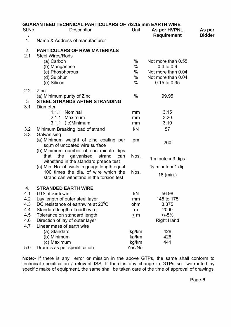
GUARANTEED TECHNICAL PARTICULARS OF 7/3.15 mm EARTH WIRE Sl.No
. Description Unit As per HVPNL
Requirement As per Bidder
1. Name & Address of manufacturer
2. PARTICULARS OF RAW MATERIALS 2.1 Steel Wires/Rods
(a) Carbon (b) Manganese (c) Phosphorous (d) Sulphur (e) Silicon
% % % % %
Not more than 0.55
0.4 to 0.9 Not more than 0.04 Not more than 0.04
0.15 to 0.35
2.2 Zinc (a) Minimum purity of Zinc
%
99.95
3 STEEL STRANDS AFTER STRANDING 3.1
Diameter 1.1.1 Nominal 2.1.1 Maximum 3.1.1 ( c)Minimum
mm mm mm
3.15 3.20 3.10
3.2 Minimum Breaking load of strand kN 57 3.3 Galvanising
(a) Minimum weight of zinc coating per sq.m of uncoated wire surface
(b) Minimum number of one minute dips that the galvanised strand can withstand in the standard preece test
(c) Min. No. of twists in guage length equal 100 times the dia. of wire which the strand can withstand in the torsion test
gm
Nos.
Nos.
260
1 minute x 3 dips
½ minute x 1 dip
18 (min.)
4. STRANDED EARTH WIRE 4.1 UTS of earth wire kN 56.98 4.2 Lay length of outer steel layer mm 145 to 175 4.3 DC resistance of earthwire at 200C ohm 3.375 4.4 Standard length of earth wire m 2000 4.5 Tolerance on standard length + m +/-5% 4.6 Direction of lay of outer layer Right Hand 4.7 Linear mass of earth wire
(a) Standard (b) Minimum (c) Maximum
kg/km kg/km kg/km
428 426 441
5.0 Drum is as per specification Yes/No Note:- If there is any error or mission in the above GTPs, the same shall conform to technical specification / relevant ISS. If there is any change in GTPs so warranted by specific make of equipment, the same shall be taken care of the time of approval of drawings
Page-6

GUARANTEED TECHNICAL PARTICULARS OF ANTI-FOG DISC INSULATOR UNITS
FOR 132KV LINES WITH ACSR PANTHER CONDUCTOR As per HVPNL
Requirement As per Bidder
S.N Description Unit 70KN 90KN 70KN 90KN 1. Name of manufacturer 2. Address of manufacturer 3. Weight of single disc Kg. As per make 4. Size and Designation of pin ball shank mm 16
Alt-B 16
Alt-B
5. Diameter of disc mm 255 255 6. Tolerance on Diameter mm 11 11 7. Ball to ball spacing between Disc mm 145 145 8. Tolerance on spacing mm 4 4 9. Minimum nominal creepage distance of single
disc mm 432 432
10 Tolerance on creepage distance mm 11. Electromechanical strength of disc kN 70 90 12. Material of shell (Porcelain ) Porc
elain Porcela
in
13. Power frequency flashover voltage of single disc
(a) dry kV(rms) 95 95 (b) wet kV(rms) 55 55 14. Power frequency withstand voltage of single
disc
(a) Dry kV(rms) 85 85 (b) Wet kV(rms) 50 50 15. Power frequency puncture voltage of single
disc kV(rms) 130 130
16. Impulse flashover voltage of single disc (dry) (a) Positive kV(peak) 150 150 (b) Negative kN(peak) 150 150 17. Impulse withstand voltage of single disc (dry) (a) Positive kV(peak) 140 140 (b) Negative kN(peak) 140 140 18. Steepness of impulse voltage which the disc
insulators can withstand in steep wave front test
kV / microsec.
19. Visible discharge test of single disc (dry) kV(rms) 9 9 20. Maximum RIV at 1MHz and 10kV AC (rms)
voltage of single disc Microvolts 50 50
21. Purity of zinc used for galvanizing % 99.95 99.95 22. No. of dips in standard piece test (a) Socket (b) Ball Pin 23. Axial and Radial run out (According to IEC) (a) As per pointer A mm (b) As per pointer B mm 24. Drawings enclosed
Note:- If there is any error or mission in the above GTPs, the same shall conform to technical specification / relevant ISS. If there is any change in GTPs so warranted by specific make of equipment, the same shall be taken care of the time of approval of drawings
Page-7

GUARANTEED TECHNICAL PARTICULARS OF SUSPENSION HARDWARE FITTINGS (SUITABLE FOR ACSR PANTHER CONDUCTOR) Sl.No Description Unit As per HVPNL
Requirement As per Bidder
1. Name of manufacturer 2. Address of manufacturer 3. Dimensioned drawings of insulator strings
enclosed
4. Detailed dimensional drawings of all hardware components enclosed
5. Material of all components indicated in drawings
6. Maximum magnetic power loss of suspension assembly at conductor current of 500 Ampere
Watts
1
7. Slipping strength of suspension assembly (clamp torque Vs slip curve shall be enclosed
KN
11 to 16
8. Particulars of standard / AGS preformed armour rod set for suspension assemble (a) No. of rods per set (b) Direction of lay (c) Overall length after fitting on Conductor (d) Actual length of each rod along its helix(e) Diameter of each rod (f) Tolerance in
(i) Diameter of each rod (ii) Length of each rod (iii) Difference of length
Between the longest and shorted rod in a set (g) Type of Aluminium alloy used for manufacture of PA rod set (h) UTS of each rod
No.
Mm
Mm Mm
+ mm + mm mm
Kg/ mm
Standard/AGS
11 Right Hand
1930 mm+/-16
2011+/-16 6.35 +/- 0.10
+/- 0.1 +/- 2.5 +/- 13
High strength
aluminium alloy Grade 6061
35
9. Particulars of Elastometer (for AGS Clamp only) (a) Supplier of elastometer (b) Type of elastometer (c) Shore hardness of elastometer (d) Temperature range for which elastometer is designed (e) Moulded on insert
As per make Neoprene
65-80 Up to 100 deg.C
Yes
Page-8
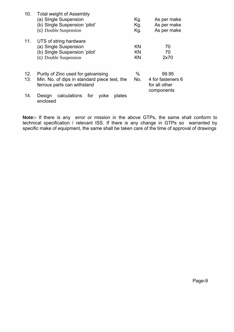
10. Total weight of Assembly (a) Single Suspension (b) Single Suspension ‘pilot’ (c) Double Suspension
Kg. Kg. Kg.
As per make As per make As per make
11.
UTS of string hardware (a) Single Suspension (b) Single Suspension ‘pilot’ (c) Double Suspension
KN KN KN
70 70
2x70
12. Purity of Zinc used for galvanising % 99.95 13. Min. No. of dips in standard piece test, the
ferrous parts can withstand No. 4 for fasteners 6
for all other components
14. Design calculations for yoke plates enclosed
Note:- If there is any error or mission in the above GTPs, the same shall conform to technical specification / relevant ISS. If there is any change in GTPs so warranted by specific make of equipment, the same shall be taken care of the time of approval of drawings
Page-9
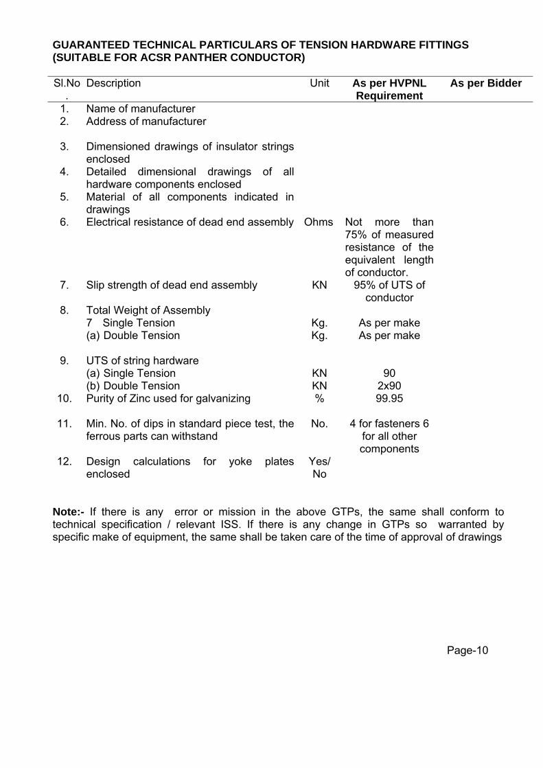
GUARANTEED TECHNICAL PARTICULARS OF TENSION HARDWARE FITTINGS (SUITABLE FOR ACSR PANTHER CONDUCTOR) Sl.No
. Description Unit As per HVPNL
Requirement As per Bidder
1. Name of manufacturer 2. Address of manufacturer
3. Dimensioned drawings of insulator strings enclosed
4. Detailed dimensional drawings of all hardware components enclosed
5. Material of all components indicated in drawings
6. Electrical resistance of dead end assembly
Ohms Not more than 75% of measured resistance of the equivalent length of conductor.
7. Slip strength of dead end assembly
KN 95% of UTS of conductor
8. Total Weight of Assembly 7 Single Tension (a) Double Tension
Kg. Kg.
As per make As per make
9. UTS of string hardware (a) Single Tension (b) Double Tension
KN KN
90
2x90
10. Purity of Zinc used for galvanizing
% 99.95
11. Min. No. of dips in standard piece test, the ferrous parts can withstand
No. 4 for fasteners 6 for all other components
12. Design calculations for yoke plates enclosed
Yes/ No
Note:- If there is any error or mission in the above GTPs, the same shall conform to technical specification / relevant ISS. If there is any change in GTPs so warranted by specific make of equipment, the same shall be taken care of the time of approval of drawings
Page-10

GUARANTEED TECHNICAL PARTICULARS OF DISC INSULATOR STRINGS (WITH DISC INSULATORS) ALONG WITH HARDWARE FITTINGS Sl.No.
Description Unit Single Suspension 1x9
Double
Tension
2x10
Single Tensi
on 1x10
Double Suspension 2x9
Single Suspension Pilot
1x9
1. Power frequency withstands voltage of string with arcing horns under wet condition.
Kv
(rms)
275 275 275 275 275
650 650 650 650 650 2. Impulse withstand voltage (dry)
(a) Positive
(b) Negative
kv
(peak)
kv (peak)
650 650 650 650 650
700 700 700 700 700 3. Impulse flashover voltage (dry)
(a) Positive
(b) Negative
kv
(peak)
kv (peak)
700 700 700 700 700
4. Mechanical strength of complete insulator string along with hardware fittings for lines with ACSR Panther
kN
70 2x90 90 2x70 70
Mechanical strength of complete insulator string along with hardware fittings for lines with ACSR Zebra
kN
70 2x120 120 2x70 70
5.
Maximum voltage distribution across any disc of line to earth voltage
%
20 22 22 20 20
6. Dimensioned drawings of insulator strings enclosed
Yes/No
Yes
Note:- If there is any error or mission in the above GTPs, the same shall conform to technical specification / relevant ISS. If there is any change in GTPs so warranted by specific make of equipment, the same shall be taken care of the time of approval of drawings
Page-11

PARTICULARS OF MID SPAN COMPRESSION JOINT FOR ACSR ‘PANTHER’
Sr. No.
Description Unit As per HVPNL Requirement
As per Bidder
1. Manufacturer’s Name and Address
2. Drawing enclosed
3. Suitable for Conductor size mm ACSR Panther
4. Purity of Aluminium used for Aluminium sleeve. 99.5%(min.)
5. Material for steel sleeve i) Type of material with chemical
composition. ii) Hardness of material (Brinnel Hardness) ii) weight of zinc coating
gm/mm2
Mid steel as per
IS:2062 160 (Max) 610 (min.)
6. Outside diameter of sleeve before compression i) Aluminium ii) Steel
(mm) (mm)
38.00+/-1.0 18.00+/-0.5
7. Inside diameter of sleeve before compression (a)Aluminium b) Steel c) Aluminium filler sleeves
(mm) (mm) (mm)
23.00+/-0.5 9.3.+/-0.2
8. Length of Aluminium Sleeve i) Before compression ii) after compression
(mm) (mm)
610.00+/-5 203.00+/-5
9. Dimensions of sleeve after compression (a) Aluminium
(i) Corner to corner (ii) Surface to surface b) Steel (i) Corner to corner (ii) Surface to surface
(mm) (mm)
(mm) (mm)
37.00+/-0.5 32.00+/-0.5
17+/-0.5 15.1+/-0.5
10. Length of Steel sleeve i) Before compression ii) after compression
(mm) (mm)
650.00+/-10 225.00 +/-5
11. Weight of sleeve (a) Aluminium (b) Steel (c) Filler Al-Sleeve
(Kg.) (Kg.) (Kg.)
As per outline
general arrangement
drawing of the manufacture
12. Slipping Strength (kN) 95% UTS of Conductor
13. Conductivity of the compressed unit expressed as percentage of the conductivity of equivalent length of bare conductor
%
Not less than that of ACSR Panther
Note:- If there is any error or mission in the above GTPs, the same shall conform to technical specification / relevant ISS. If there is any change in GTPs so warranted by specific make of equipment, the same shall be taken care of the time of approval of drawings
Page-12

PARTICULARS OF REPAIR SLEEVE FOR ACSR ‘PANTHER’ CONDUCTOR Sl.No
. Description Unit As per HVPNL
Requirement As per Bidder
1. Manufacturer’s Name and Address
2. Drawing enclosed
3. Suitable for conductor size (mm) ACSR Panther
4. Purity of aluminium used for aluminium sleeve
(%)
95.5 (min.)
5. Inside diameter of sleeve before compression
(mm) 23.00+/-0.5
6. Outside dimensions of sleeve (a) Dia Before compression (b) After Compression
(i) Corner to corner (ii) Surface to surface
(mm)
(mm) (mm)
38.00+/-1.0 37.00+/-0.5 32.00+/-0.5
7. Length of sleeve (a) Before compression
(b) After compression
(mm)
(mm)
241+/-5 260+/-5
8. Weight of Sleeve (Kg)
As per outline general
arrangement drawing of the manufacture
Note:- If there is any error or mission in the above GTPs, the same shall conform to technical specification / relevant ISS. If there is any change in GTPs so warranted by specific make of equipment, the same shall be taken care of the time of approval of drawings
Page-13
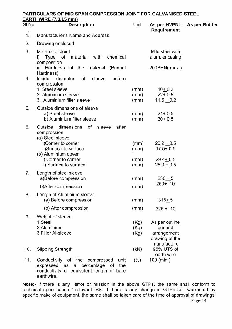
PARTICULARS OF MID SPAN COMPRESSION JOINT FOR GALVANISED STEEL EARTHWIRE (7/3.15 mm) Sl.No
. Description Unit As per HVPNL
Requirement As per Bidder
1. Manufacturer’s Name and Address
2. Drawing enclosed
3. Material of Joint i) Type of material with chemical composition ii) Hardness of the material (Brinnel Hardness)
Mild steel with alum. encasing
200BHN( max.)
4. Inside diameter of sleeve before compression 1. Steel sleeve 2. Aluminium sleeve 3. Aluminium filler sleeve
(mm) (mm) (mm)
10+ 0.2 22+ 0.5
11.5 + 0.2
5. Outside dimensions of sleeve a) Steel sleeve b) Aluminium filter sleeve
(mm) (mm)
21+ 0.5 30+ 0.5
6. Outside dimensions of sleeve after compression (a) Steel sleeve
i)Corner to corner ii)Surface to surface
(b) Aluminium cover i) Corner to corner ii) Surface to surface
(mm) (mm)
(mm) (mm)
20.2 + 0.5 17.5+ 0.5
29.4+ 0.5 25.0 + 0.5
7. Length of steel sleeve a)Before compression
b)After compression
(mm)
(mm)
230 + 5
260+ 10
8. Length of Aluminium sleeve (a) Before compression
(b) After compression
(mm)
(mm)
315+ 5
325 + 10
9. Weight of sleeve 1.Steel 2.Aluminium 3.Filler Al-sleeve
(Kg) (Kg) (Kg)
As per outline
general arrangement
drawing of the manufacture
10. Slipping Strength (kN) 95% UTS of earth wire
11. Conductivity of the compressed unit expressed as a percentage of the conductivity of equivalent length of bare earthwire.
(%)
100 (min.)
Note:- If there is any error or mission in the above GTPs, the same shall conform to technical specification / relevant ISS. If there is any change in GTPs so warranted by specific make of equipment, the same shall be taken care of the time of approval of drawings Page-14

GUARANTEED TECHNICAL PARTICULARS OF VIBRATION DAMPER FOR ACSR ‘PANTHER’ CONDUCTOR
Sl.No Description Unit As per
HVPNL Requirement
As per Bidder
1. Manufacturer’s Name & Address 2. Drawing enclosed
(a) Design drawing (b) Placement chart
3. Suitable for conductor size mm ACSR PANTHER
4. Total weight of one damper Kg
As per make
5. Diameter of each damper mass mm AS per outline general
arrangement drawing of the manufacture
6. Length of each damper mass mm 7. Weight of each damper mass Kg 8. Material of damper masses Cast Iron
H.D.G.
9. Material of the stranded messenger cable
High strength galvanized steel stranded wire
10. Number of strands in stranded messenger cable
Mm 19
11. Lay ratio of stranded messenger cable
9 to 11
12. Minimum ultimate tensile strength of stranded messenger cable
(Kg/ mm)
135.00
13. Slipping strength of stranded messenger cable (mass pull off)
KN 5 (min.)
14.
Resonance frequencies (a) First frequency (b) Second frequency
Hz Hz
As per outline general
arrangement drawing of the manufacture
15. Designed clamping torque Kg-m 6.5 16. Slipping strength of damper clamp
(a) Before fatigue test (b) After fatigue test
KN KN
2.5 2.0
17 Magnetic Power loss at 350Amp. Watts 1 watt per damper (max.)
18 Material of Clamp Alum. Alloy (grad LM-6
Note:- If there is any error or mission in the above GTPs, the same shall conform to technical specification / relevant ISS. If there is any change in GTPs so warranted by specific make of equipment, the same shall be taken care of the time of approval of drawings . Page-15
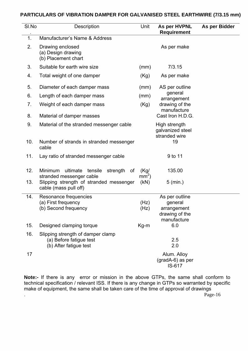
PARTICULARS OF VIBRATION DAMPER FOR GALVANISED STEEL EARTHWIRE (7/3.15 mm) Sl.No
. Description Unit As per HVPNL
Requirement As per Bidder
1. Manufacturer’s Name & Address
2. Drawing enclosed (a) Design drawing (b) Placement chart
As per make
3. Suitable for earth wire size (mm) 7/3.15
4. Total weight of one damper (Kg) As per make
5. Diameter of each damper mass (mm)
6. Length of each damper mass (mm)
7. Weight of each damper mass (Kg)
AS per outline general
arrangement drawing of the manufacture
8. Material of damper masses Cast Iron H.D.G.
9. Material of the stranded messenger cable
High strength galvanized steel stranded wire
10. Number of strands in stranded messenger cable
19
11. Lay ratio of stranded messenger cable
9 to 11
12. Minimum ultimate tensile strength of stranded messenger cable
(Kg/mm2)
135.00
13. Slipping strength of stranded messenger cable (mass pull off)
(kN)
5 (min.)
14.
Resonance frequencies (a) First frequency (b) Second frequency
(Hz) (Hz)
As per outline general
arrangement drawing of the manufacture
15. Designed clamping torque Kg-m 6.0
16. Slipping strength of damper clamp (a) Before fatigue test (b) After fatigue test
2.5 2.0
17 Alum. Alloy (gradA-6) as per
IS-617
Note:- If there is any error or mission in the above GTPs, the same shall conform to technical specification / relevant ISS. If there is any change in GTPs so warranted by specific make of equipment, the same shall be taken care of the time of approval of drawings . Page-16

PARTICULARS OF SUSPENSION CLAMP FOR GALVANISED STEEL EARTHWIRE (7/3.15 mm) Sl.No
. Description Unit As per HVPNL
Requirement As per Bidder
1. Manufacturer’s Name & Address
2. Drawing enclosed
3. Material i) Shackle ii) Clamp Body & Keeper iii) U – Bolt
Class 4 as IS-2004
MCI Mid steel
4. Total drop (maximum) (mm) 118+/-2
5. Weight (Kg) As per outline general
arrangement drawing of the manufacture
6. Breaking Strength (minimum) (kgf) 25
7. Slipping Strength (kN) 9 to 14
8. Tightening Torque (kg-m) 4 to 6
Note:- If there is any error or mission in the above GTPs, the same shall conform to technical specification / relevant ISS. If there is any change in GTPs so warranted by specific make of equipment, the same shall be taken care of the time of approval of drawings .
Page-17
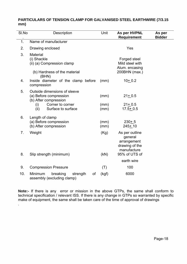
PARTICULARS OF TENSION CLAMP FOR GALVANISED STEEL EARTHWIRE (7/3.15 mm) Sl.No
. Description Unit As per HVPNL
Requirement As per Bidder
1. Name of manufacturer
2. Drawing enclosed Yes
3. Material (i) Shackle (ii) (a) Compression clamp (b) Hardness of the material (BHN)
Forged steel
Mild steel with Alum. encasing 200BHN (max.)
4. Inside diameter of the clamp before compression
(mm)
10+ 0.2
5. Outside dimensions of sleeve (a) Before compression (b) After compression
(i) Corner to corner (ii) Surface to surface
(mm)
(mm) (mm)
21+ 0.5
21+ 0.5
17.5+ 0.5
6. Length of clamp (a) Before compression (b) After compression
(mm) (mm)
230+ 5 245+ 10
7. Weight
(Kg)
As per outline general
arrangement drawing of the manufacture
8. Slip strength (minimum) (kN) 95% of UTS of
earth wire
9. Compression Pressure (T) 100
10. Minimum breaking strength of assembly (excluding clamp)
(kgf) 6000
Note:- If there is any error or mission in the above GTPs, the same shall conform to technical specification / relevant ISS. If there is any change in GTPs so warranted by specific make of equipment, the same shall be taken care of the time of approval of drawings .
Page-18

GUARANTEED TECHNICAL PARTICULARS OF FLEXIBLE COPPER BOND Sl.No
. Description Unit As per HVPNL
Requirement As per Bidder
1. Name of manufacturer
2. Drawing enclosed
3. Stranding 37/7/0.417 mm
4. Cross sectional area (Sq.mm) 34
5. Minimum copper equivalent area (Sq.mm) 34
6. Length of copper cable (mm) 500 (min.)
7. Material of lugs Tinned copper alloy
8. Bolt Size (i) Diameter (ii) Length
(mm) (mm)
16 40
9. Resistance (Ohm) 0.0002536
10. Total weight of flexible copper bond (kg)
As per OGA drawing of the manufacture
Note:- If there is any error or mission in the above GTPs, the same shall conform to technical specification / relevant ISS. If there is any change in GTPs so warranted by specific make of equipment, the same shall be taken care of the time of approval of drawings
Page-19

GUARANTEED TECHNICAL PARTICULARS & OTHER TECHNICAL DATA OF 132KV POST INSULATOR Sl.No. Description Unit As per HVPNL
Requirement
As per Bidder
1. Height mm 1220+/-1
2. Power frequency dry one minute withstand voltage
KV
275
3. Impulse withstand voltage rms 550
4. Total creepage distance mm 3625
5. Protected creepage distance mm As per HVPNL
Specification
6. Cantilever strength inverted Kg As per HVPNL
Specification
7. Cantilever strength upright Kg As per HVPNL Specification
8. Tensile strength N As per HVPNL Specification
9. Torsional strength Nm As per HVPNL Specification
10. Compression strength N As per HVPNL Specification
11. Bending strength N As per HVPNL Specification
12. Type and make
13. Total weight Kg AS per OGA drawing
14. Pitch circle diameter a. Bottom
b. Top
mm
mm
As per HVPNL Specification As per HVPNL Specification
15. Max. diameter of Insulators mm As per HVPNL
Specification
16. Drawing Reference No.
Note:- If there is any error or mission in the above GTPs, the same shall conform to technical specification / relevant ISS. If there is any change in GTPs so warranted by specific make of equipment, the same shall be taken care of the time of approval of drawings
Page-20