about the tutorial - current affairs 2018, apache commons ... · power electronics i about the...
TRANSCRIPT


Power Electronics
i
About the Tutorial
Power Electronics refers to an interdisciplinary subject within electrical engineering
that deals with the design, control and conversion of power in its electric form. A system
that converts electric energy to an electric load through a control circuit is known as a
Power Electronic System.
The purpose of this tutorial is to introduce and explain the main concepts in Power
Electronics, which include Power Semi-Conductor Devices, Phase-Controlled Converters,
DC to DC Converter, Inverters and AC to AC Converters.
Audience
The target of this tutorial is electrical engineering students. It is a good resource to help
them gain knowledge on electronics and circuits as applied in power electronics.
Prerequisites
This tutorial is meant for novice readers. Almost anyone with a basic knowledge of
electronics can make the most of this tutorial. It is difficult to avoid complex
mathematics at some places, although we have tried to keep it at a minimum level.
Therefore it is expected that the readers are comfortable with mathematical equations.
Copyright & Disclaimer
Copyright 2015 by Tutorials Point (I) Pvt. Ltd.
All the content and graphics published in this e-book are the property of Tutorials Point
(I) Pvt. Ltd. The user of this e-book is prohibited to reuse, retain, copy, distribute or
republish any contents or a part of contents of this e-book in any manner without written
consent of the publisher.
We strive to update the contents of our website and tutorials as timely and as precisely
as possible, however, the contents may contain inaccuracies or errors. Tutorials Point (I)
Pvt. Ltd. provides no guarantee regarding the accuracy, timeliness or completeness of
our website or its contents including this tutorial. If you discover any errors on our
website or in this tutorial, please notify us at [email protected]

Power Electronics
ii
Table of Contents
About the Tutorial .......................................................................................................................................... i Audience ......................................................................................................................................................... i Prerequisites ................................................................................................................................................... i Copyright & Disclaimer ................................................................................................................................... i Table of Contents........................................................................................................................................... ii
UNIT 1: BASICS ................................................................................................................................. 1
1. Power Electronics – Introduction ............................................................................................................ 2 Static Applications ......................................................................................................................................... 2 Drive Applications .......................................................................................................................................... 3
2. Power Electronics – Switching Devices .................................................................................................... 4
3. Power Electronics – Linear Circuit Elements ............................................................................................ 5 Resistors ........................................................................................................................................................ 5 Capacitors ...................................................................................................................................................... 6 Inductors ........................................................................................................................................................ 6 Transformers ................................................................................................................................................. 7 Additional Devices ......................................................................................................................................... 8
UNIT 2: POWER SEMICONDUCTOR DEVICES .......................................................................... 9
4. Power Electronics – Silicon Controlled Rectifier (SCR) ........................................................................... 10
5. Power Electronics – TRIAC ..................................................................................................................... 12
6. Power Electronics – BJT ......................................................................................................................... 14
7. Power Electronics – IGBT ....................................................................................................................... 17
8. Power Electronics – MOSFET ................................................................................................................. 19
9. Power Electronics – Solved Example ..................................................................................................... 20
UNIT 3: PHASE CONTROLLED CONVERTERS ........................................................................ 21
10. Power Electronics – Pulse Converters .................................................................................................... 22 Phase Controlled Converter......................................................................................................................... 22 2- Pulse Converter ....................................................................................................................................... 23 3-Pulse Converter ........................................................................................................................................ 23 6-Pulse Converter ........................................................................................................................................ 24
11. Power Electronics – Effect of Source Inductance ................................................................................... 26 Effect on Single Phase .................................................................................................................................. 26 Effect on Three Phase .................................................................................................................................. 27
12. Power Electronics – Performance Parameters ....................................................................................... 28

Power Electronics
iii
13. Power Electronics – Reactive Power Control of Converters ................................................................... 30
14. Power Electronics – Dual Converters ..................................................................................................... 31 Battery Charger............................................................................................................................................ 31 Types of Battery Chargers............................................................................................................................ 32
15. Power Electronics – Solved Example ..................................................................................................... 33
UNIT 4: DC TO DC CONVERTERS ............................................................................................... 34
16. Power Electronics – Choppers ............................................................................................................... 35 Step Up Chopper.......................................................................................................................................... 35 Step Down Chopper ..................................................................................................................................... 37 Step Up/ Step Down Chopper...................................................................................................................... 40
17. Power Electronics – Methods of Control ............................................................................................... 42 Time Ratio Control ....................................................................................................................................... 42 Current Limit Control ................................................................................................................................... 42
18. Power Electronics – Resonant Switching ............................................................................................... 43 Resonant DC to DC Converters .................................................................................................................... 43 Switched Mode Power Supply (SMPS)......................................................................................................... 43
19. Power Electronics – Solved Example ..................................................................................................... 46
UNIT 5: INVERTERS....................................................................................................................... 47
20. Power Electronics – Types of Inverters .................................................................................................. 48 Single Phase Inverter ................................................................................................................................... 48 Three Phase Inverter ................................................................................................................................... 48
21. Power Electronics – Pulse Width Modulation (PWM) ............................................................................ 52 Sinusoidal Pulse Width Modulation............................................................................................................. 52 Modified Sinusoidal Waveform PWM ......................................................................................................... 53 Multiple PWM.............................................................................................................................................. 54 Voltage and Harmonic Control .................................................................................................................... 54 Series Resonant Inverter ............................................................................................................................. 55
22. Power Electronics – Solved Example ..................................................................................................... 56
23. Power Electronics – Single Phase AC Voltage Controllers ...................................................................... 58
24. Power Electronics – Cycloconverters ..................................................................................................... 59
25. Power Electronics – Integral Cycle Control ............................................................................................ 60
26. Power Electronics – Matrix Converters.................................................................................................. 62
27. Power Electronics – Solved Example ..................................................................................................... 63

Power Electronics
1
Unit 1: Basics

Power Electronics
2
Power Electronics refers to the process of controlling the flow of current and voltage and
converting it to a form that is suitable for user loads. The most desirable power
electronic system is one whose efficiency and reliability is 100%.
Take a look at the following block diagram. It shows the components of a Power
Electronic system and how they are interlinked.
A power electronic system converts electrical energy from one form to another and
ensures the following is achieved-
Maximum efficiency
Maximum reliability
Maximum availability
Minimum cost
Least weight
Small size
Applications of Power Electronics are classified into two types: Static Applications and
Drive Applications.
Static Applications
This utilizes moving and/or rotating mechanical parts such as welding, heating, cooling,
and electro-plating and DC power.
DC Power Supply
1. Power Electronics – Introduction
Power Electronics
3
Drive Applications
Drive applications have rotating parts such as motors. Examples include compressors,
pumps, conveyer belts and air conditioning systems.
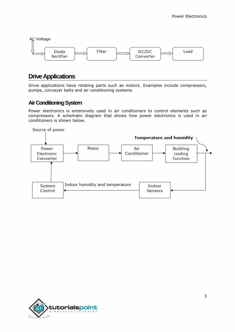
Air Conditioning System
Power electronics is extensively used in air conditioners to control elements such as
compressors. A schematic diagram that shows how power electronics is used in air
conditioners is shown below.

Power Electronics
4
A power electronic switching device is a combination of active switchable power
semiconductor drivers that have been integrated into one. The main characteristics of
the switch are determined by internal correlation of functions and interactions of its
integrated system. The figure given below shows how a power electronic switch system
works.
The external circuit of the above diagram is usually held at a high potential relative to
the control unit. Inductive transmitters are used to support the required potential
difference between the two interfaces.
Power switching devices are normally selected based on the rating at which they handle
power, that is, the product of their current and voltage rating instead of their power
dissipation rate. Consequently, the major attractive feature in a power electronic switch
is its capability to dissipate low or almost no power. As a result, the electronic switch
able to achieve a low and continuous surge of power.
Drive Power semiconductor
devices (e.g IGBTs)
Galvanic isolation
snubbers
Control
Unit
Supply
Power
GI1
1
GI2
2. Power Electronics – Switching Devices

Power Electronics
5
Linear circuit elements refer to the components in an electrical circuit that exhibit a
linear relationship between the current input and the voltage output. Examples of
elements with linear circuits include;
Resistors
Capacitors
Inductors
Transformers
To get a better understanding of linear circuit elements, an analysis of resistor elements
is necessary.
Resistors
A resistor is a device in which the flow of an electric current is restricted resulting in an
energy conversion. For example, when electricity flows through a light bulb, the
electricity is converted into a different form of energy such as heat and/or light. The
resistance of an element is measured in ohms (Ω).
The measure of resistance in a given circuit is given by:
𝑹 = 𝝆𝑳
𝑨
Where R - resistance; ρ – resistivity; L - length of wire; and A - cross-sectional area of
wire
Symbol of Various Resistors
Resistor
A variable resistor
A potentiometer
3. Power Electronics – Linear Circuit Elements
Power Electronics
6
Capacitors
A capacitor refers to an electrical device that has two conducting materials (also known
as plates) separated by an insulator known as a dielectric. It uses electric field to store
electric energy. The electric field is developed when the capacitor is connected to a
battery, thus making positive electric charges accumulate on one plate and negative
electric charges on the other plate.
When energy is stored in the electrical field of a capacitor, the process is called charging,
and when energy is removed, the process is called discharging. The level of electrical
energy stored in a capacitor is called capacitance and is measured in farads (F). One
farad is the same as one coulomb per unit volt given by 1 C/V.
The difference between a capacitor and a battery is that a capacitor stores electrical
energy while a battery stores chemical energy and releases the energy at a slow rate.
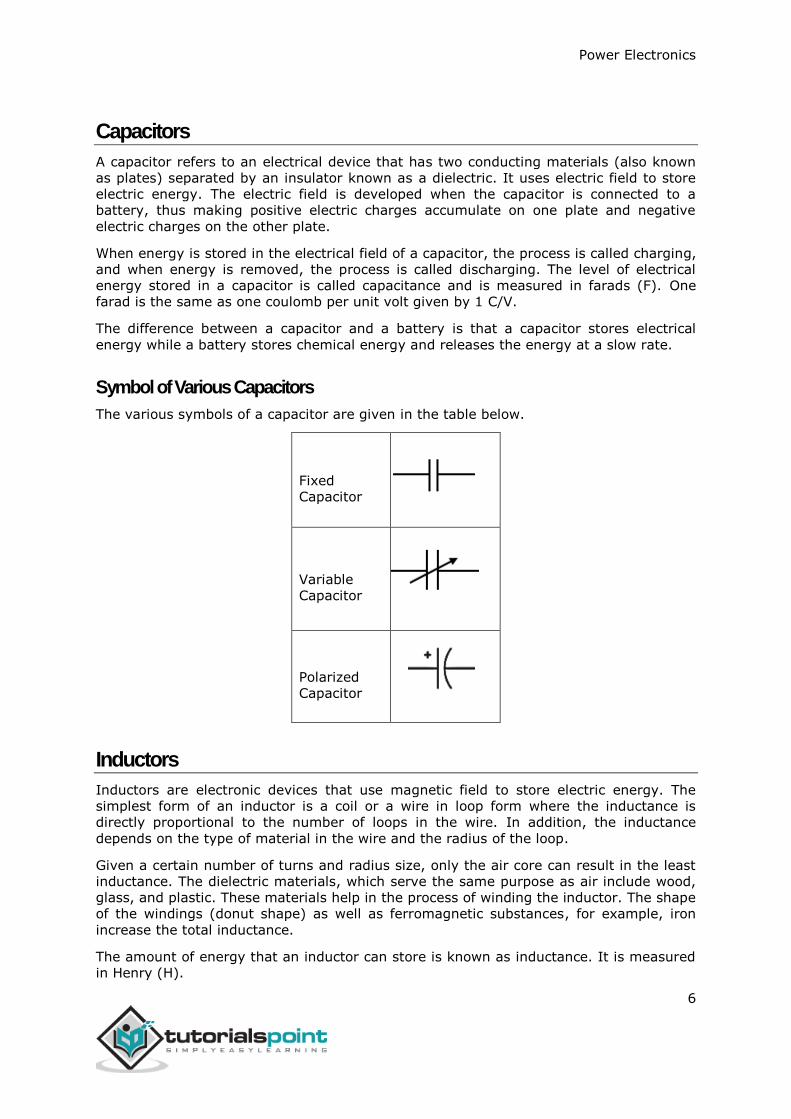
Symbol of Various Capacitors
The various symbols of a capacitor are given in the table below.
Fixed
Capacitor
Variable
Capacitor
Polarized
Capacitor
Inductors
Inductors are electronic devices that use magnetic field to store electric energy. The
simplest form of an inductor is a coil or a wire in loop form where the inductance is
directly proportional to the number of loops in the wire. In addition, the inductance
depends on the type of material in the wire and the radius of the loop.
Given a certain number of turns and radius size, only the air core can result in the least
inductance. The dielectric materials, which serve the same purpose as air include wood,
glass, and plastic. These materials help in the process of winding the inductor. The shape
of the windings (donut shape) as well as ferromagnetic substances, for example, iron
increase the total inductance.
The amount of energy that an inductor can store is known as inductance. It is measured
in Henry (H).

Power Electronics
7
Symbol of Various Inductors
Fixed
inductor
Variable
inductor
Transformers
This refers to a device that alters energy from one level to another through a process
known as electromagnetic induction. It is usually used to raise or lower AC voltages in
applications utilizing electric power.
When the current on the primary side of the transformer is varied, a varied magnetic
flux is created on its core, which spreads out to the secondary windings of the
transformer in form of magnetic fields.
The operation principle of a transformer relies on Faraday’s law of electromagnetic
induction. The law states that the rate of change of the flux linking with respect to time
is directly related to the EMF induced in a conductor.
A transformer has three main parts;
Primary winding
Magnetic core
Secondary winding
Figure: Schematic of a transformer
Power Electronics
8
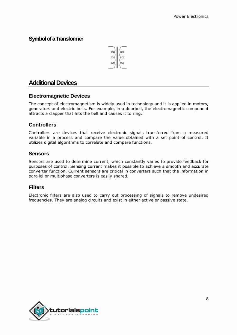
Symbol of a Transformer
Additional Devices
Electromagnetic Devices
The concept of electromagnetism is widely used in technology and it is applied in motors,
generators and electric bells. For example, in a doorbell, the electromagnetic component
attracts a clapper that hits the bell and causes it to ring.
Controllers
Controllers are devices that receive electronic signals transferred from a measured
variable in a process and compare the value obtained with a set point of control. It
utilizes digital algorithms to correlate and compare functions.
Sensors
Sensors are used to determine current, which constantly varies to provide feedback for
purposes of control. Sensing current makes it possible to achieve a smooth and accurate
converter function. Current sensors are critical in converters such that the information in
parallel or multiphase converters is easily shared.
Filters
Electronic filters are also used to carry out processing of signals to remove undesired
frequencies. They are analog circuits and exist in either active or passive state.

Power Electronics
9
Unit 2: Power Semiconductor Devices

Power Electronics
10
A silicon controlled rectifier or semiconductor-controlled rectifier is a four-layer solid-
state current-controlling device. The name "silicon controlled rectifier" is General
Electric's trade name for a type of thyristor.
SCRs are mainly used in electronic devices that require control of high voltage and
power. This makes them applicable in medium and high AC power operations such as
motor control function.
An SCR conducts when a gate pulse is applied to it, just like a diode. It has four layers of
semiconductors that form two structures namely; NPNP or PNPN. In addition, it has three
junctions labeled as J1, J2 and J3 and three terminals(anode, cathode and a gate). An
SCR is diagramatically represented as shown below.
The anode connects to the P-type, cathode to the N-type and the gate to the P-type as
shown below.
In an SCR, the intrinsic semiconductor is silicon to which the required dopants are
infused. However, doping a PNPN junction is dependent on the SCR application.
4. Power Electronics – Silicon Controlled Rectifier (SCR)

Power Electronics
11

Power Electronics
12
End of ebook preview
If you liked what you saw…
Buy it from our store @ https://store.tutorialspoint.com